EP4094973A1 - Dispositif de stockage de batterie et véhicule électrique - Google Patents
Dispositif de stockage de batterie et véhicule électrique Download PDFInfo
- Publication number
- EP4094973A1 EP4094973A1 EP22174635.7A EP22174635A EP4094973A1 EP 4094973 A1 EP4094973 A1 EP 4094973A1 EP 22174635 A EP22174635 A EP 22174635A EP 4094973 A1 EP4094973 A1 EP 4094973A1
- Authority
- EP
- European Patent Office
- Prior art keywords
- battery
- operation lever
- pressing member
- storing unit
- storage device
- Prior art date
- Legal status (The legal status is an assumption and is not a legal conclusion. Google has not performed a legal analysis and makes no representation as to the accuracy of the status listed.)
- Pending
Links
- 230000008878 coupling Effects 0.000 claims abstract description 92
- 238000010168 coupling process Methods 0.000 claims abstract description 92
- 238000005859 coupling reaction Methods 0.000 claims abstract description 92
- 230000007246 mechanism Effects 0.000 description 27
- 230000008859 change Effects 0.000 description 4
- 238000000034 method Methods 0.000 description 4
- 230000008569 process Effects 0.000 description 4
- 238000006243 chemical reaction Methods 0.000 description 2
- 238000012986 modification Methods 0.000 description 2
- 230000004048 modification Effects 0.000 description 2
- XLYOFNOQVPJJNP-UHFFFAOYSA-N water Substances O XLYOFNOQVPJJNP-UHFFFAOYSA-N 0.000 description 2
- 230000009471 action Effects 0.000 description 1
- 230000001419 dependent effect Effects 0.000 description 1
- 230000000994 depressogenic effect Effects 0.000 description 1
- 238000010586 diagram Methods 0.000 description 1
- 239000011347 resin Substances 0.000 description 1
- 229920005989 resin Polymers 0.000 description 1
Images


Classifications
-
- B—PERFORMING OPERATIONS; TRANSPORTING
- B62—LAND VEHICLES FOR TRAVELLING OTHERWISE THAN ON RAILS
- B62J—CYCLE SADDLES OR SEATS; AUXILIARY DEVICES OR ACCESSORIES SPECIALLY ADAPTED TO CYCLES AND NOT OTHERWISE PROVIDED FOR, e.g. ARTICLE CARRIERS OR CYCLE PROTECTORS
- B62J43/00—Arrangements of batteries
- B62J43/10—Arrangements of batteries for propulsion
- B62J43/16—Arrangements of batteries for propulsion on motorcycles or the like
-
- B—PERFORMING OPERATIONS; TRANSPORTING
- B60—VEHICLES IN GENERAL
- B60L—PROPULSION OF ELECTRICALLY-PROPELLED VEHICLES; SUPPLYING ELECTRIC POWER FOR AUXILIARY EQUIPMENT OF ELECTRICALLY-PROPELLED VEHICLES; ELECTRODYNAMIC BRAKE SYSTEMS FOR VEHICLES IN GENERAL; MAGNETIC SUSPENSION OR LEVITATION FOR VEHICLES; MONITORING OPERATING VARIABLES OF ELECTRICALLY-PROPELLED VEHICLES; ELECTRIC SAFETY DEVICES FOR ELECTRICALLY-PROPELLED VEHICLES
- B60L50/00—Electric propulsion with power supplied within the vehicle
- B60L50/50—Electric propulsion with power supplied within the vehicle using propulsion power supplied by batteries or fuel cells
- B60L50/60—Electric propulsion with power supplied within the vehicle using propulsion power supplied by batteries or fuel cells using power supplied by batteries
- B60L50/66—Arrangements of batteries
-
- B—PERFORMING OPERATIONS; TRANSPORTING
- B62—LAND VEHICLES FOR TRAVELLING OTHERWISE THAN ON RAILS
- B62J—CYCLE SADDLES OR SEATS; AUXILIARY DEVICES OR ACCESSORIES SPECIALLY ADAPTED TO CYCLES AND NOT OTHERWISE PROVIDED FOR, e.g. ARTICLE CARRIERS OR CYCLE PROTECTORS
- B62J1/00—Saddles or other seats for cycles; Arrangement thereof; Component parts
- B62J1/12—Box-shaped seats; Bench-type seats, e.g. dual or twin seats
-
- B—PERFORMING OPERATIONS; TRANSPORTING
- B62—LAND VEHICLES FOR TRAVELLING OTHERWISE THAN ON RAILS
- B62J—CYCLE SADDLES OR SEATS; AUXILIARY DEVICES OR ACCESSORIES SPECIALLY ADAPTED TO CYCLES AND NOT OTHERWISE PROVIDED FOR, e.g. ARTICLE CARRIERS OR CYCLE PROTECTORS
- B62J43/00—Arrangements of batteries
- B62J43/20—Arrangements of batteries characterised by the mounting
- B62J43/23—Arrangements of batteries characterised by the mounting dismounted when charging
-
- B—PERFORMING OPERATIONS; TRANSPORTING
- B62—LAND VEHICLES FOR TRAVELLING OTHERWISE THAN ON RAILS
- B62J—CYCLE SADDLES OR SEATS; AUXILIARY DEVICES OR ACCESSORIES SPECIALLY ADAPTED TO CYCLES AND NOT OTHERWISE PROVIDED FOR, e.g. ARTICLE CARRIERS OR CYCLE PROTECTORS
- B62J43/00—Arrangements of batteries
- B62J43/20—Arrangements of batteries characterised by the mounting
- B62J43/28—Arrangements of batteries characterised by the mounting hidden within the cycle frame
-
- B—PERFORMING OPERATIONS; TRANSPORTING
- B62—LAND VEHICLES FOR TRAVELLING OTHERWISE THAN ON RAILS
- B62J—CYCLE SADDLES OR SEATS; AUXILIARY DEVICES OR ACCESSORIES SPECIALLY ADAPTED TO CYCLES AND NOT OTHERWISE PROVIDED FOR, e.g. ARTICLE CARRIERS OR CYCLE PROTECTORS
- B62J9/00—Containers specially adapted for cycles, e.g. panniers or saddle bags
- B62J9/10—Containers specially adapted for cycles, e.g. panniers or saddle bags integrated with the cycle
- B62J9/14—Containers specially adapted for cycles, e.g. panniers or saddle bags integrated with the cycle under the saddle
-
- B—PERFORMING OPERATIONS; TRANSPORTING
- B60—VEHICLES IN GENERAL
- B60L—PROPULSION OF ELECTRICALLY-PROPELLED VEHICLES; SUPPLYING ELECTRIC POWER FOR AUXILIARY EQUIPMENT OF ELECTRICALLY-PROPELLED VEHICLES; ELECTRODYNAMIC BRAKE SYSTEMS FOR VEHICLES IN GENERAL; MAGNETIC SUSPENSION OR LEVITATION FOR VEHICLES; MONITORING OPERATING VARIABLES OF ELECTRICALLY-PROPELLED VEHICLES; ELECTRIC SAFETY DEVICES FOR ELECTRICALLY-PROPELLED VEHICLES
- B60L2200/00—Type of vehicles
- B60L2200/12—Bikes
-
- B—PERFORMING OPERATIONS; TRANSPORTING
- B62—LAND VEHICLES FOR TRAVELLING OTHERWISE THAN ON RAILS
- B62K—CYCLES; CYCLE FRAMES; CYCLE STEERING DEVICES; RIDER-OPERATED TERMINAL CONTROLS SPECIALLY ADAPTED FOR CYCLES; CYCLE AXLE SUSPENSIONS; CYCLE SIDE-CARS, FORECARS, OR THE LIKE
- B62K2202/00—Motorised scooters
-
- Y—GENERAL TAGGING OF NEW TECHNOLOGICAL DEVELOPMENTS; GENERAL TAGGING OF CROSS-SECTIONAL TECHNOLOGIES SPANNING OVER SEVERAL SECTIONS OF THE IPC; TECHNICAL SUBJECTS COVERED BY FORMER USPC CROSS-REFERENCE ART COLLECTIONS [XRACs] AND DIGESTS
- Y02—TECHNOLOGIES OR APPLICATIONS FOR MITIGATION OR ADAPTATION AGAINST CLIMATE CHANGE
- Y02E—REDUCTION OF GREENHOUSE GAS [GHG] EMISSIONS, RELATED TO ENERGY GENERATION, TRANSMISSION OR DISTRIBUTION
- Y02E60/00—Enabling technologies; Technologies with a potential or indirect contribution to GHG emissions mitigation
- Y02E60/10—Energy storage using batteries
Definitions
- the present invention relates to a battery storage device and an electric vehicle.
- WO2015/068753A1 discloses the motorcycle in which a plurality of batteries are detachable. This vehicle reduces weight of each battery while ensuring the total capacity of the batteries, thereby facilitating the battery attachment and detachment work.
- the battery case In the vehicle of WO2015/068753A1 , the battery case is disposed below the seat. The battery stored in the battery case is pushed downward by the spring provided on the lower surface of the seat. This reduces the vertical movement of the battery when the vehicle is running. When the force to press and hold the battery is increased by the spring, the force required for the operator to close the lid (the seat in WO 2015/068753A1 ) becomes large, and the load at the time of attaching and detaching the battery thereby becomes large.
- FIG. 1 the directions indicated by Fr and Bc are referred to as a forward direction and a rearward direction, respectively, and the directions indicated by Up and Dw are referred to as a upward direction and a downward direction, respectively.
- the directions indicated by R and L shown in FIG. 3 are referred to as a right direction and a left direction, respectively.
- the electric vehicle proposed in the present disclosure is not limited to an electric two-wheeled vehicle, but may be an electric three-wheeled vehicle or an electric four-wheeled vehicle called an ATV (All Terrain Vehicle) or an ROV (Recreational Off-Highway Vehicle).
- ATV All Terrain Vehicle
- ROV Recreational Off-Highway Vehicle
- the electric two-wheeled vehicle 1 includes a handle bar 2, a steering shaft (not shown) supporting the handle bar 2, a front fork 3 that rotates integrally with the steering shaft, and a front wheel 4 supported by the front fork 3.
- the electric two-wheeled vehicle 1 includes a seat 5 and batteries 70A and 70B that are disposed below the seat 5.
- the electric two-wheeled vehicle 1 may have a plurality of batteries 70A and 70B.
- the number of the batteries 70A and 70B may be two, for example.
- the two batteries 70A and 70B may be aligned in the front-rear direction. Unlike the illustrated example, the number of batteries may be one or more than two. In yet another example, the two batteries 70A and 70B may be aligned in the left-right direction.
- the electric two-wheeled vehicle 1 includes a power unit 6 that is driven by power received from the batteries 70A and 70B.
- the power unit 6 includes an inverter (not shown) for converting direct current from the batteries 70A and 70B to alternating current, and an electric motor (not shown) driven by power from the inverter.
- the electric two-wheeled vehicle 1 is a so-called scooter-type vehicle.
- the electric vehicle proposed in this disclosure is not limited to a scooter-type motorcycle.
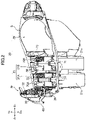
- the electric two-wheeled vehicle 1 includes a battery storage device S (see FIG. 2 ).
- the battery storage device S is disposed below the seat 5.
- the battery storage device S includes a case 20.
- the case 20 includes a battery storing unit 21 in which the batteries 70A and 70B are insertable.
- the case 20 may also include a luggage compartment 29 for storing luggage, such as a helmet, behind the battery storing unit 21.
- the battery storing unit 21 may be formed such that a plurality of batteries 70A and 70B are insertable. As shown in FIG. 2 , the battery storing unit 21 may include two storing units 21A and 21B disposed in the front-rear direction, for example. The two batteries 70A and 70B may be respectively insertable in the storing units 21A and 21B. The storing units 21A and 21B are box-shaped open upward, for example, and the batteries 70A and 70B are insertable from the upper side of the storing units 21A and 21B. The battery storing unit 21 and the luggage compartment 29 are covered with the sheet 5. When the sheet 5 is opened, the batteries 70A and 70B are to be inserted into or removed from the storing unit 21A and 21B. Terminals are provided inside the storing units 21A and 21B for electrically connecting to the batteries 70A and 70B.
- the batteries 70A and 70B may have terminals 74 (see FIG. 1 ) between their upper and lower ends. Specifically, the terminals 74 may be provided on the side surfaces of the batteries 70A and 70B. A terminal for connecting to the terminals 74 may be provided on the inside of the battery storing units 21. The power of the batteries 70A and 70B is supplied to the electric motor through such a terminal.
- the positions of the terminals 74 are apart upwardly from the lower ends of the batteries 70A and 70B, and thus it is possible to avoid splashing of water on the terminals 74 when traveling in areas where water is gathered, for example.
- the position of the terminal 74 is not limited to the example described above, and may be provided on the lower surface of the batteries 70A and 70B, for example.
- the two batteries 70A and 70B may be independently removable from or insertable into the storing units 21A and 21B. That is, only one battery 70A (or 70B) may be removable from the storing unit 21A (or 21B) or attachable to the storing unit 21A (or 21B).
- the two batteries 70A and 70B may have the same structure. In this case, the battery 70B disposed on the rear side in FIG. 2 may be inserted into the storing unit 21A on the front side, and the battery 70A disposed on the front side may be inserted into the storing unit 21B on the rear side.
- the power unit 6 may be driven with only one battery 70A (or 70B) mounted in the battery storage device S. That is, the batteries 70A and 70B may be connected in parallel. In this manner, when one battery 70A (or 70B) is removed from the electric two-wheeled vehicle 1 and charged by an external power source, the other battery 70B (or 70A) is mounted on the electric two-wheeled vehicle 1 so as to run the electric two-wheeled vehicle 1. Alternatively, two batteries 70A and 70B may be required to drive the power unit 6.
- the storing units 21A and 21B may be formed to store substantially the entire batteries 70A and 70B. That is, the depth of the storing units 21A and 21B may correspond to the height of the batteries 70A and 70B.
- the storing units 21A and 21B may store only the lower portions of the batteries 70A and 70B, and the upper portions of the batteries 70A and 70B may be exposed from the storing units 21A and 21B.
- the storing units 21A and 21B may not be box-shaped.
- the storing units 21A and 21B may be formed to support the batteries 70A and 70B, but expose most of the outer surfaces of the batteries 70A and 70B.
- the storing units 21A and 21B may be formed to insert the batteries 70A and 70B from the left side (or right side) rather than from the upper side thereof.
- a lid to be used for exposing the batteries 70A and 70B may be provided on an outer cover 11 (see FIG. 1 ) of the electric two-wheeled vehicle 1. This also facilitate charging of the batteries 70A and 70B.
- a battery locking mechanism M (see FIG. 2 ) to be described later may be disposed on the left (or right) side of the batteries 70A and 70B and covered by the lid provided on the outer cover 11.
- the luggage compartment 29 is also box-shaped open upward. By opening the seat 5, the luggage can be put into or taken out from the luggage compartment 29.
- the inside of the battery storing unit 21 and the inside of the luggage compartment 29 may be connected to each other. That is, a space may be formed in the inside of the battery storing unit 21 and the inside of the luggage compartment 29 to be connected with each other.
- the inside of the storing unit 21B in the rear side may be connected to the inside of the luggage compartment 29. That is, a wall needs not be formed to divide the storing unit 21B on the rear side and the luggage compartment 29.
- this structure allows large luggage to be stored in the storing unit 21B and the luggage compartment 29.
- the luggage compartment 29 and the battery storing unit 21 may be integrally formed. This serves to reduce the number of parts. Alternatively, the luggage compartment 29 and the battery storing unit 21 may be formed separately.
- the luggage compartment 29 and the battery storing unit 21 may be fixed to each other by a fixture, such as a screw, or each of the luggage compartment 29 and the battery storing unit 21 may be fixed to the vehicle body frame. In yet another example, the case 20 may not have the luggage compartment 29.
- the electric two-wheeled vehicle 1 has a battery locking mechanism M (see FIG. 2 ).
- the battery locking mechanism M includes a pressing member 31 that restricts upward movement of the batteries 70A and 70B stored in the storing units 21A and 21B.
- the battery locking mechanism M includes an operation lever 41 connected to the pressing member 31 for the operator to operate.
- the battery locking mechanism M includes an engaged portion 51 to be engaged with the engaging the operation lever 41.
- the engaged portion 51 may be formed on a support member 50. As will be described later, the support member 50 may be attached to the case 20 or the body frame, for example.
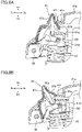
- a support shaft 38 (see FIG. 6 ) is provided on the base of the pressing member 31.
- the pressing member 31 is movable between the closed position (see FIGs. 6A and 6B ) and the open position (see FIG. 6C ) around the support shaft 38.
- the support shaft 38 is provided such that its center line is along the left-right direction.
- the pressing member 31 When in the closed position, the pressing member 31 is positioned above the batteries 70A and 70B and restricts the upward movement of the batteries 70A and 70B (the movement in the direction of removing things from the storing units 21A and 21B).
- the pressing member 31 allows the batteries 70A and 70B to move upward.
- the pressing member 31 may extend rearward from the support shaft 38 when in the closed position ( FIG. 6A ) and extend upward from the support shaft 38 when in the open position ( FIG. 6C ).
- a plurality of batteries 70A and 70B can be stored in the battery storing unit 21.
- the pressing member 31 is positioned above the plurality of batteries 70A and 70B when in the closed position ( FIG. 6A ) to restrict upward movement of the batteries 70A and 70B. This structure serves to restrict the movement of the batteries 70A and 70B with less operation.
- the number of batteries stored in the battery storing unit 21 may be greater than two. In this case, the pressing member 31 may be sized to cover all the batteries. Unlike the illustrated example, the number of batteries that the battery storing unit 21 can store may be one.
- the support shaft 38 is fitted into a supported hole formed in the base (the front end in the example shown in the drawing) of the pressing member 31 to support the pressing member 31.
- the support shaft 38 is supported by a support member 39 (see FIG. 4 ).
- the support member 39 is attached to the case 20, for example.
- the support member 39 is attached to the front side of the battery storing unit 21. This allows the case 20 and the battery locking mechanism M to be treated as one component in the assembly process of the electric two-wheeled vehicle 1, thereby facilitating the assembly operation.
- the support member 39 may be attached to the body frame (not shown).
- the pressing member 31 may include a retainer 37 (see FIG. 4 ) for preventing the support shaft 38 from coming off from the supported hole formed in the base thereof.
- the supporting structure of the pressing member 31 is not limited to the illustrated example.
- the support shaft 38 may be formed integrally with the pressing member 31.
- the support shaft 38 may be a convex portion protruding rightward and leftward from the base of the pressing member 31.
- the support member 39 may hold the support shaft (convex portion) while allowing the rotation of the support shaft.
- the lower side of the pressing member 31 includes contact portions 32 (see FIGs. 2 and 5 ) that are in contact with the upper surfaces of the batteries 70A and 70B.
- the pressing member 31 may include an elastic member 33 that pushes the contact portions 32 downward.
- the elastic member 33 is a coil spring, for example.
- the pressing member 31 may have two contact portions 32 for each of the batteries 70A and 70B. Alternatively, the number of contact portions 32 provided for each of the batteries 70A and 70B may be one or more than two.
- the contact portion 32 itself may be formed of an elastic member such as rubber. In this case, the pressing member 31 may not have a coil spring, which is an elastic member 33.
- the pressing member 31 includes a front pressing portion 31A at its front portion. Further, the pressing member 31 includes a rear pressing portion 31B at its rear portion. When the pressing member 31 is in the closed position, the front pressing portion 31A is positioned above the battery 70A on the front side, and the rear pressing portion 31B is positioned above the battery 70B on the rear side.
- the pressing portions 31A and 31B each include the contact portions 32 for pushing the batteries 70A and 70B downward.
- the contact portion 32 provided on the battery 70A on the front side is positioned forward than the center Pva of the battery 70A in the front-rear direction.
- the contact portion 32 provided on the battery 70B on the rear side is positioned forward than the center Pvb of the battery 70B in the front-rear direction.
- the contact portions 32 are respectively positioned toward the support shaft 38 with respect to the centers Pva and Pvb of the respective batteries 70A and 70B. This structure reduces the distance between the contact portion 32 and the support shaft 38, thereby increasing the lever ratio.
- the pressing member 31 may include left and right extending portions 31c extending rearward from the left portion and the right portion of the front pressing portion 31A and respectively connected to the left portion and the right portion of the rear pressing portion 31B.
- the pressing member 31 may include openings inside the front pressing portion 31A, the rear pressing portion 31B, and the right and left extending portions 31c.
- the upper surface of the battery 70A may be partially exposed through the openings.
- a charging inlet 73 to be described later may be provided on the upper surface of the batteries 70A and 70B. The charging inlet 73 may be exposed to the upper side through the openings described above.
- the shape of the pressing member 31 is not limited to the illustrated example.
- the pressing member 31 may not have the openings described above. That is, the pressing member 31 may be a plate-shaped member covering the upper surface of the batteries 70A and 70B in a plan view.
- the operation lever 41 is connected to the pressing member 31 via a coupling shaft 49 (see FIG. 4 ) at a position away from the support shaft 38 (see FIG. 6 ).
- the operation lever 41 is connected to the rear pressing portion 31B on the rear portion of the pressing member 31.
- the coupling shaft 49 is provided such that its center line is along the left-right direction.
- the operation lever 41 is movable relative to the pressing member 31 between a fixed position ( FIG. 6A ) and a release position ( FIGs. 6B and 6C ) about the coupling shaft 49.
- the operation lever 41 includes an operation input portion 41a and an engaging portion 42.
- the operation lever 41 includes the operation input portion 41a at the center of the operation lever 41 in the left-right direction.
- the operation lever 41 may include a coupled portion 41d and the engaging portion 42 respectively on the right side and left side in its rear portion.
- the coupled portion 41d is a portion where the coupling shaft 49 is provided.
- the engaging portion 42 is a portion that engages the engaged portion 51 provided in the case 20 and the body frame.
- the coupled portion 41d may be located on the side of the rear pressing portion 31B and connected to the rear pressing portion 31B via the coupling shaft 49.
- the coupling shaft 49 is a bolt, for example, but may be a convex portion integrally formed with the pressing member 31 or a convex portion integrally formed with the operation lever 41.
- the operation lever 41 may include left and right extending portions 41b extending rearward from the left portion and the right portion of the operation input portion 41a.
- the extending portions 41b are connected to the coupled portion 41d and the engaging portion 42.
- the operation lever 41 may include openings inside the operation input portion 41a, the right and left extending portions 41b, and the left and right coupled portions 41d, and the left and right engaging portions 42.
- the upper surface of the battery 70A may be partially exposed through the openings. This shape of the operation lever 41 serves to reduce the weight of the operation lever 41.
- the charging inlet 73 provided on the top surface of the battery 70A may be exposed to the upper side through the openings. This facilitates charging operation of the battery 70A (operation of connecting a cable to the charging inlet 73).
- the shape of the operation lever 41 is not limited to the illustrated example.
- the operation lever 41 may not include the openings described above. That is, the operation lever 41 may be a plate-shaped member covering the upper surface of the batteries 70A and 70B in a plan view.
- the direction in which the pressing member 31 extends from the support shaft 38 may be opposite to the direction in which the operation lever 41 extends from the coupling shaft 49.
- the pressing member 31 extends rearward from the support shaft 38.
- the operation lever 41 extends forward from the coupling shaft 49. This arrangement of the pressing member 31 and the operation lever 41 serves to reduce the size of the battery locking mechanism M in the front-rear direction.
- the operation lever 41 When in the fixed position, the operation lever 41 may overlap the pressing member 31. This arrangement of the operation lever 41 serves to reduce the size of the battery locking mechanism M in the front-rear direction. When in the released position, the operation lever 41 may be apart from the pressing member 31 upwardly. The front end 41c of the operation lever 41 may be positioned rearward than the front end 31d of the pressing member 31.
- the engaging portion 42 and the engaged portion 51 are engaged with each other.
- the distance L1 between the operation input portion 41a and the coupling shaft 49 may be longer than the distance L2 between the engaging portion 42 and the coupling shaft 49. This serves to secure the sufficient lever ratio.
- the distance L1 is a distance between the most distant position of the operation input portion 41a from the coupling shaft 49 (the front end of the upper surface of the operation input portion 41a in the illustrated example) and the center of the coupling shaft 49.
- the distance L2 is a distance between the portion of the engaging portion 42 in contact with the engaged portion 51 and the center of the coupling shaft 49.
- the structure described above including the pressing member 31, the operation lever 41, and the engaged portion 51 facilitate the attaching operation of the battery described below. That is, the operator inserts the battery 70A (and/or 70B) into the battery storing unit 21 with the pressing member 31 being at the open position ( FIG. 6C ). The operator then moves the pressing member 31 to the closed position ( FIG. 6B ). The operator engages the engaging portion 42 of the operation lever 41 to the engaged portion 51, pushes down the operation input portion 41a of the operation lever 41, and moves the operation lever 41 from the release position ( FIG. 6B ) to the fixed position ( FIG. 6A ). This restricts upward movement of the batteries 70A and 70B.
- the structure enabling such an attaching operation it is possible to reduce the force required for the operator to attach the batteries 70A and 70B to the storing units 21A and 21B. This results in facilitating the operation of attaching and detaching the batteries 70A and 70B. Further, the size of the battery locking mechanism M in the front-rear direction can be reduced.
- the operation input portion 41a may be the central portion of the operation lever 41 in the left-right direction. Further, the operation input portion 41a may include a surface facing upward in a state where the pressing member 31 is in the closed position and the operation lever 41 is in the fixed position ( FIG. 6A ). This serves to smoothly perform the operation of pressing the operation lever 41.
- the operation input portion 41a may be a portion in which the distance between the coupling shaft 49 and the operation input portion 41a is greater than the distance L2 (see FIG. 6A ) between the engaging portion 42 and the coupling shaft 49, and its shape and position are not limited to the illustrated example.
- the operation lever 41 may be a plate-shaped member that covers the upper side of the rear portion of the pressing member 31 (rear pressing portion 31B) and/or covers the upper side of the front portion of the pressing member 31 (front pressing portion 31A). In this case, the front portion of the operation lever 41 may function as the operation input portion 41a.
- the operation lever 41 may include a handle for the operator to grip as the operation input portion 41a.
- the arrangement of the pressing member 31 and the operation lever 41 is not limited to the illustrated example.
- the pressing member 31 may extend forward from the support shaft 38 and the operation lever 41 may extend rearward from the coupling shaft 49.
- the pressing member 31 may extend rearward from the support shaft 38, and the operation lever 41 may extend downward from the coupling shaft 49.
- the operation lever 41 when in the fixed position, the operation lever 41 may be located behind the battery 70B on the rear side.
- the engaged portion 51 is attached to the support member 50.
- the support member 50 may be attached to the case 20, for example (see FIG. 2 ).
- This structure allows the engaged portion 51, the battery locking mechanism M, and the battery storing unit 21 to be interconnected. As such, they can be handled as a single component in the assembly processing of the electric two-wheeled vehicle 1, and it is thereby possible to facilitate the assembly operation.
- the support member 50 is attached to the inner surfaces of the right wall portion and the left wall portion of the case 20 (in other words, the side wall portion 21 (left wall portion and right wall portion) of the battery storing unit 21).
- the engaged portion 51 projects from the support member 50 toward the right wall portion and the left wall portion of the case 20.
- the support member 50 may be attached to the body frame.
- the engaged portion 51 may be directly attached to the case 20 or to the body frame.
- the engaging portion 42 may be hook-shaped.
- the engaged portion 51 may be a convex portion protruding from the support member 50 toward the side wall 21a of the battery storing unit 21.
- the engaging portion 42 may be L-shaped.
- the engaging portion 42 includes a lower portion 42a and a front portion 42b.
- the front portion 42b is positioned in front of the engaged portion 51 in a state where the pressing member 31 is in the closed position and the operation lever 41 is in the fixed position.
- the lower portion 42a extends rearward from the front portion 42b and is located below the engaged portion 51.
- the position of the coupling shaft 49 is positioned lower than the position of the coupling shaft 49 when the operation lever 41 is in the release position ( FIG. 6B ).
- the pressing member 31 pushes the batteries 70A and 70B downward to restrict the movement of the batteries 70A and 70B in the removing direction (upward).
- the engaging portion 42 includes a contact surface 42c at its inner edge.
- the contact surface 42c is in contact with the engaged portion 51 when the operation lever 41 is in the released position.
- the position of the contact surface 42c is lowered.
- the shape of the engaging portion 42 and the position and shape of the engaged portion 51 are determined such that the position of the contact surface 42c is changed in this manner.
- the engaged portion 51 may be cylindrical with a center line C1 along the left-right direction.
- the engaged portion 51 may be rotatable about the center line C1. In this manner, it is possible to prevent the movement of the engaging portion 42 from being inhibited by friction between the engaged portion 51 and the engaging portion 42 caused in the process in which the engaging portion 42 is engaged with the engaged portion 51, that is, the engaged portion 51 is moved along the inner surface (contact surface 42c) of the engaging portion 42.
- the structures of the engaged portion 51 and the engaging portion 42 are not limited to the illustrated example if the coupling shaft 49 can be depressed along with the movement of the operation lever 41.
- the shapes of the engaging portion 42 and the engaged portion 51 may be opposite to the illustrated example. That is, the engaged portion 51 may have a hook shape that opens forward.
- the engaging portion 42 of the operation lever 41 may be a convex portion (e.g., cylinder) protruding in the left-right direction toward the side wall of the battery storing unit 21. This structure allows the engaging portion 42, which is a convex portion, to enter the inside of the engaged portion 51, which is hook-shaped, with the movement of the operation lever 41, thereby establishing the engagement between the engaging portion 42 and the engaged portion 51.
- the entire operation lever 41 (operation input portion 41a, extending portion 41b, engaging portion 42) is integrally formed.
- the entire operation lever 41 may be formed of resin, for example. This serves to reduce the number of parts.
- the engaging portion 42 is also movable about the coupling shaft 49 with the movement of the operation input portion 41a about the coupling shaft 49, the operation input portion 41a, the extending portion 41b, and the engaging portion 42 may be separately formed and fixed to each other by a fixture such as a screw.
- the operation input portion 41a and the extending portion 41b may be integrally formed, and the engaging portion 42 may be separately formed.
- the engaging portion 42 may be attached to the operation input portion 41a and the extending portion 41b by a fixture such as a screw.
- the operation lever 41 may include an elastic member for biasing the operation lever 41 from the fixed position ( FIG. 6A ) toward the release position ( FIGs. 6B , 6C ). With the use of the elastic member, it is possible to facilitate the operation of returning the operation lever 41 to the release position.
- the spring 48 (see FIG. 6B ) may be used as the elastic member.
- the spring 48 is a torsion coil spring, for example, and the coupling shaft 49 is fitted inside the spring 48.
- a stopper member 61 (see FIG. 4 ) to be described later is provided at the front portion of the pressing member 31 (front pressing portion 31A in the illustrated example). Movement of the operation lever 41 from the fixed position ( FIG. 6A ) to the release position ( FIG. 6B ) may be restricted by the stopper member 61.
- the seat 5 is disposed above the case 20 and the battery locking mechanism M.
- the seat 5 includes a supported portion 5a at the foremost portion thereof.
- the supported portion 5a is supported by the shaft portion 5e, and the seat 5 is disposed rearward from the shaft portion 5e.
- the sheet 5 is movable up and down between the closed position ( FIG. 1 , non-exposed position) and the open position (exposed position) about the shaft portion 5e.
- the operation lever 41 When the pressing member 31 is in the closed position and the operation lever 41 is in the released position, the operation lever 41 extends obliquely forward and upward from the coupling shaft 49.
- the operation lever 41 prevents the sheet 5 from moving to the closed position. This prevents the driver from operating the electric two-wheeled vehicle 1 without the operation lever 41 being in the fixed position.
- the seat 5 includes a cushion 5b and a seat bottom 5c fixed to the lower side of the cushion 5b.
- a stopped portion 5d may be formed on the seat bottom 5c.
- the stopped portion 5d may be a convex portion protruding downward, for example.
- the front end of the operation lever 41 contacts the stopped portion 5d.
- the stopped portion 5d may be one of ribs 5f protruding from the lower surface of the seat bottom 5c so as to increase the intensity of the seat bottom 5c.
- the operation lever 41 When the front end of the operation lever 41 restricts the movement of the seat 5 in this manner, the operation lever 41 may extend in a direction intersecting the straight line L3 extending from the shaft portion 5e of the sheet 5 to the stopped portion 5d. In other words, when the operation lever 41 is in the released position, the operation lever 41 may extend in a direction substantially perpendicular to the straight line L3. This serves to strongly restrict the movement of the seat 5.
- the structure for restricting the movement of the seat 5 is not limited to the illustrated example.
- the movement of the seat 5 may be restricted by the pressing member 31 in the open position.
- the seat 5 may include a shaft 5e at its rear end and be movable between the seat open position and the seat closed position about the shaft portion 5e.
- the extending direction of the pressing member 31 in the open position may intersect with the straight line extending from the shaft portion 5e of the seat 5 to the stopped portion 5d.
- the member covering the battery locking mechanism M and the batteries 70A and 70B may be a special cover instead of the seat 5.
- an opening for removing and inserting the batteries 70A and 70B may be formed in the outer cover 11 ( FIG. 1 ) on the left (or right) side.
- a special cover for opening and closing the opening may be provided.
- the support shaft 38 is positioned forward than the front surface 70a of the battery 70A on the front side.
- the coupling shaft 49 is positioned rearward than the rear surface 70b of the battery 70A. This serves to secure the lever ratio and the force from the pressing member 31 acting on the battery 70A.
- the coupling shaft 49 when the pressing member 31 is in the closed position, the coupling shaft 49 is positioned forward than the rear surface 70b of the battery 70B on the rear side. More specifically, the center C2 of the coupling shaft 49 is positioned forward than the rear surface 70b of the battery 70B on the rear side.
- This arrangement of the coupling shaft 49 serves to easily ensure a large space (luggage compartment 29 in the illustrated example) rearward than the battery 70B on the rear side.
- the coupling shaft 49 may be positioned forward than the rear surface 70b of the battery located on the rear side.
- the center C2 of the coupling shaft 49 may be positioned forward than the center Pvb of the battery 70B in the front-rear direction and rearward than the front surface 70a of the battery 70B. This makes it easier to ensure a large space (luggage compartment 29 in the illustrated example) behind the battery 70B on the rear side while securing the force acting on the battery 70B on the rear side from the pressing member 31.
- the center C2 of the coupling shaft 49 may be positioned forward than the uppermost portion (handle 71 in the illustrated example) of the battery 70B on the rear side.
- the center C2 of the coupling shaft 49 may be positioned lower than the upper end 71a of the battery 70B on the rear side.
- This arrangement of the coupling shaft 49 serves to lower the positions of the coupling shaft 49 and the rear pressing portion 31B. Consequently, the size of the batteries 70A and 70B can be sufficiently ensured in the vertical direction while properly keeping the position of the seat 5. Further, a large space can be easily provided behind the battery 70B.
- the batteries 70A and 70B include handles 71 (see FIG. 2 ) for the operator to grip at their uppermost portions.
- the handles 71 protrude upward from the upper surfaces of main bodies 70e of the batteries 70A and 70B (see FIG. 6A ).
- the main body 70e is a portion that stores a battery cell.
- the center C2 of the coupling shaft 49 may be positioned in front of the handle 71.
- the center C2 of the coupling shaft 49 may be located lower than the upper end 71a (upper surface) of the handle 71.
- the coupling shaft 49 connects the operation lever 41 to the rear pressing portion 31B.
- the rear surface 31e of the pressing member 31 may be positioned forward than the rear surface 70b of the battery 70B on the rear side. This reduces the size of the battery locking mechanism M in the front-rear direction.
- the rear surface 31e of the pressing member 31 may be positioned forward than the uppermost portion (handle 71) of the battery 70B.
- the rear surface 31e may be positioned below the upper end 71a of the battery 70B (the upper surface of the handle 71). This arrangement serves to lower the height of the battery locking mechanism M, thereby preventing the position of the battery locking mechanism M from affecting the height of the seat 5.
- a portion of the rear surface 31e may be positioned upward of the upper end 71a of the battery 70B (the upper surface of the handle 71).
- the engaged portion 51 may be positioned below the coupling shaft 49.
- This arrangement of the engaged portion 51 serves to reduce the size of the battery locking mechanism M including the engaged portion 51 in the front-rear direction as compared with the case where the engaged portion 51 is formed behind the coupling shaft 49, for example, while appropriately maintaining the distance between the coupling shaft 49 and the engaged portion 51 (the length of the engaging portion 42).
- the engaged portion 51 may be positioned forward than the rear surface 70b of the battery 70B on the rear side. More specifically, the engaged portion 51 may be positioned forward than the center Pvb of the battery 70B in the front-rear direction. This can reduce the size of the battery locking mechanism M including the engaged portion 51 in the front-rear direction.
- the support member 50 supporting the engaged portion 51 may be also positioned forward than the rear surface 70b of the battery 70B on the rear side.
- the positions of the rear pressing portion 31B, the coupled portion 41d of the operation lever 41, and the coupling shaft 49 are higher than the upper surface of the main body 70e of the battery 70B.
- the width of the rear pressing portion 31B in the left-right direction is smaller than the width of the battery 70B in the left-right direction. That is, the right end 31b of the pressing portion 31B is positioned closer to the center Cv3 than the right side surface 70f of the battery 70B in the left-right direction. Similarly, the left end of the pressing portion 31B is positioned closer to the center Cv3 than the left side surface of the battery 70B in the left-right direction.
- This arrangement and sizes of the coupling shaft 49, the rear pressing portion 31B, and the coupled portion 41d can sufficiently ensure the sizes of the batteries 70A and 70B in the left-right direction as compared with, for example, the structure where the coupling shaft 49 is disposed along the left and right sides of the main body 70e of the battery 70B.
- the width of the coupled portion 41d of the operation lever 41 may also be smaller than the width of the battery 70B in the left-right direction. That is, the coupled portion 41d on the right side may be positioned closer to the center Cv3 in the left-right direction than the right side surface 70f of the battery 70B. Similarly, the coupled portion 41d on the left side may be positioned closer to the center Cv3 in the left-right direction than the left side surface of the battery 70B. This serves to reduce the size of the operation lever 41 in the left-right direction.
- the positional relationship between the coupling shaft 49 and the battery 70B on the rear side described above may be applied to the positional relationship between the coupling shaft 49 and the rearmost battery (e.g., the third battery).
- the positional relation between the rear pressing portion 31B and the battery 70B on the rear side described above may be applied to the rearmost battery (e.g., the third battery).
- the sizes of the coupling shaft 49 and the pressing member 31 are not limited to the illustrated examples.
- the coupling shaft 49 may be positioned upward of the rear portion of the battery 70B on the rear side. That is, the coupling shaft 49 may be positioned rearward than the center Pvb of the battery 70B in the front-rear direction.
- the batteries 70A and 70B each include a charging inlet 73 (see FIG. 2 ) on its upper surface.
- a charging cable extending from an external power supply may be connected to the charging inlet 73.
- the batteries 70A and 70B may be charged by power received from an external power supply unit while being stored in the battery storing unit 21. This arrangement of the charging inlet 73 facilitates the operation of connecting the charging cable to the charging inlet 73.
- the charging inlets 73 may be positioned on the upper surfaces of the rear portions of the bodies 70e of the batteries 70A and 70B. More specifically, the charging inlet 73 may be positioned rearward than the handle 71 on the upper surface of the body 70e.
- the charging inlet 73 is disposed so as to be connected to the charging cable from the right side or the left side.
- the charging inlet 73 is disposed so as to face to the left. More specifically, the charging inlets 73 are disposed so as to face obliquely leftward and rearward.
- the charging inlets 73 are disposed on the right of the batteries 70A and 70B.
- the charging cables connected to the charging inlets 73 extend obliquely leftward and rearward from the charging inlets 73. This arrangement of the charging inlets 73 further facilitates the operation of connecting the charging cables to the charging inlets 73.
- the pressing member 31 and the operation lever 41 partially cover the upper sides of the batteries 70A and 70B and are formed to expose the charging inlets 73.
- the charging inlets 73 are exposed on the upper side in a state where the pressing member 31 is in the closed position and the operation lever 41 is in the fixed position in a plan view. This structure allows the batteries 70A and 70B to be charged while the pressing member 31 restricts the position change of the batteries 70A and 70B.
- the pressing member 31 has openings inside the front pressing portion 31A, the rear pressing portion 31B, and the right and left extending portions 31c.
- the operation lever 41 has a U-shape opened rearward, and has openings inside the operation input portion 41a, the right and left extending portions 41b, the left and right coupled portions 41d, and the left and right engaging portions 42.
- the charging inlet 73 of the front battery 70A on the front side is positioned inside the opening of the pressing member 31 and the opening of the operation lever 41 in a plan view and is exposed upward.
- the charging inlet 73 of the battery 70B on the rear side is positioned rearward than the rear surface 31e of the rear pressing portion 31B. As such, the charging inlet 73 of the battery 70B on the rear side is not covered by the operation lever 41 and the pressing member 31.
- the charging inlet 73 of the battery 70A on the front side may be covered by the pressing member 31 and/or the operation lever 41 in a plan view of the batteries 70A and 70B.
- the charging inlet 73 may be exposed in the direction in which the charging cable is connected to the charging inlet 73. This structure also allows the battery 70A to be charged while the pressing member 31 restricts the position change of the battery 70A.
- the battery locking mechanism M may include a stopper member 61.
- the stopper member 61 is supported by the pressing member 31.
- the stopper member 61 is hooked to the operation lever 41 to prevent the operation lever 41 from moving from the fixed position to the release position. This prevents the operation lever 41 from returning to the release position from the fixed position by the elastic force of the elastic member provided on the operation lever 41, that is, the spring 48 (see FIG. 6B ).
- the stopper member 61 may be supported in the front pressing portion 31A.
- the stopper member 61 is hooked to the front end of the operation lever 41.
- the operation lever 41 includes a stopped portion 41e protruding forward at its front end.
- the stopper member 61 includes an interference portion 61a at its rear portion. When the operation lever 41 is in the fixed position, the interference portion 61a is positioned upward of the stopped portion 41e to restrict the movement of the operation lever 41 toward the release position.
- the stopper member 61 is movable between the interference position ( FIG. 5 ) and the non-interference position ( FIG. 8B ) about the support shaft 69 provided below the stopper member 61.
- the interference portion 61a is positioned on the upper side of the stopped portion 41e to prevent the operation lever 41 in the fixed position from moving toward the release position (see FIG. 5 ).
- the operation lever 41 in the fixed position is allowed to move toward the release position (see FIG. 8B ).
- the stopper member 61 includes an elastic member that urges the stopper member 61 toward the interference position from the non-interference position.
- the spring 68 (see FIG. 5 ) may be used as the elastic member.
- the spring 68 is a torsion coil spring, for example, and the support shaft 69 may be fitted inside the spring 68.
- the support shaft 69 is positioned below the interference portion 61a. More specifically, the vertical line passing through the support shaft 69 intersects with the lower end of the interference portion 61a (the contact with the stopped portion 41e).
- the initial moving direction of the interference portion 61a is forward.
- the operation lever 41 is in the fixed position, the operation lever 41 extends forward from the coupling shaft 49. As such, when the operation lever 41 is moved from the fixed position toward the release position, the initial moving direction of the stopped portion 41e is upward.
- this structure serves to effectively prevent the operation lever 41 from moving from the fixed position toward the release position due to the vibration (e.g., vibration in the vertical direction) generated when the electric two-wheeled vehicle 1 is running.
- the interference portion 61a includes a pressed surface 61b extending obliquely rearward and downward.
- the tip of the stopped portion 41e contacts the pressed surface 61b.
- the stopped portion 41e then pushes the pressed surface 61b obliquely forward and downward.
- the stopped portion 41e contacts the pressed surface 61b and moves the stopper member 61 from the interference position to the non-interference position. That is, the operator can move the operation lever 41 from the release position toward the fixed position without operating the stopper member 61.
- the operation lever 41 is biased from the fixed position ( FIG. 6A ) toward the release position ( FIG. 6B ) by the action of the spring 48 (see FIG. 6B ).
- the stopped portion 41e includes an engaging portion 41f.
- the engaging portion 41f is a convex portion protruding upward from the front end of the stopped portion 41e, for example.
- the engaging portion 41f is engaged with the interference portion 61a when the stopper member 61 moves from the interference position ( FIG. 5 ) to the non-interference position ( FIG. 8B ) so as to restrict the movement of the stopper member 61.
- the operator is required to perform the following operation, for example, in order to move the pressing member 31 from the closed position to the open position.
- the operator presses the operation lever 41 in the fixed position ( FIG. 6A ) from the upper side to restrict the movement of the operation lever 41 toward the release position.
- the operator pushes forward an operated portion 61c formed on the upper portion of the stopper member 61 and moves the stopper member 61 from the interference position ( FIG. 5 ) toward the non-interference position ( FIG. 8B ).
- the operation lever 41 moves from the fixed position ( FIG. 6A ) toward the release position ( FIG. 6B ) by the elastic force of the spring 48.
- the battery storage device and the electric vehicle proposed in the present disclosure are not limited to the battery storage device S and electric two-wheeled vehicle 1 described above, and various modifications may be made.
- a plurality of batteries may be disposed in the left-right direction in the battery storing unit.
- the stopper member 61 may not be provided on the operation lever 41.
- the engaging portion 42 may be formed to engage the engaged portion 51 against the elastic force of the spring 48.
Applications Claiming Priority (1)
| Application Number | Priority Date | Filing Date | Title |
|---|---|---|---|
| JP2021087145A JP7315619B2 (ja) | 2021-05-24 | 2021-05-24 | バッテリ収容装置及び電動車両 |
Publications (1)
| Publication Number | Publication Date |
|---|---|
| EP4094973A1 true EP4094973A1 (fr) | 2022-11-30 |
Family
ID=81750722
Family Applications (1)
| Application Number | Title | Priority Date | Filing Date |
|---|---|---|---|
| EP22174635.7A Pending EP4094973A1 (fr) | 2021-05-24 | 2022-05-20 | Dispositif de stockage de batterie et véhicule électrique |
Country Status (2)
| Country | Link |
|---|---|
| EP (1) | EP4094973A1 (fr) |
| JP (1) | JP7315619B2 (fr) |
Citations (6)
| Publication number | Priority date | Publication date | Assignee | Title |
|---|---|---|---|---|
| DE102004047339A1 (de) * | 2004-09-29 | 2006-03-30 | Linde Ag | Vorrichtung zur Verriegelung einer Batterie eines Hubwagens |
| JP2015069823A (ja) * | 2013-09-27 | 2015-04-13 | 本田技研工業株式会社 | 電動車両のバッテリ取付構造 |
| WO2015068753A1 (fr) | 2013-11-06 | 2015-05-14 | ヤマハ発動機株式会社 | Véhicule électrique de type à selle |
| WO2019064556A1 (fr) * | 2017-09-29 | 2019-04-04 | 本田技研工業株式会社 | Dispositif de stockage de batterie pour véhicule |
| EP3480093A1 (fr) * | 2017-11-02 | 2019-05-08 | Darfon Electronics Corp. | Cadre de véhicule à deux roues |
| WO2021005767A1 (fr) * | 2019-07-10 | 2021-01-14 | 本田技研工業株式会社 | Véhicule électrique à selle |
Family Cites Families (4)
| Publication number | Priority date | Publication date | Assignee | Title |
|---|---|---|---|---|
| JP5493918B2 (ja) * | 2010-01-28 | 2014-05-14 | スズキ株式会社 | 電動式自動二輪車のバッテリ着脱構造 |
| JP6284746B2 (ja) * | 2013-11-06 | 2018-02-28 | ヤマハ発動機株式会社 | 鞍乗型電動車両 |
| JP6972321B2 (ja) * | 2018-04-26 | 2021-11-24 | 本田技研工業株式会社 | 電動車両 |
| JP6891206B2 (ja) * | 2019-03-08 | 2021-06-18 | 本田技研工業株式会社 | 電動車両のバッテリ端子構造 |
-
2021
- 2021-05-24 JP JP2021087145A patent/JP7315619B2/ja active Active
-
2022
- 2022-05-20 EP EP22174635.7A patent/EP4094973A1/fr active Pending
Patent Citations (6)
| Publication number | Priority date | Publication date | Assignee | Title |
|---|---|---|---|---|
| DE102004047339A1 (de) * | 2004-09-29 | 2006-03-30 | Linde Ag | Vorrichtung zur Verriegelung einer Batterie eines Hubwagens |
| JP2015069823A (ja) * | 2013-09-27 | 2015-04-13 | 本田技研工業株式会社 | 電動車両のバッテリ取付構造 |
| WO2015068753A1 (fr) | 2013-11-06 | 2015-05-14 | ヤマハ発動機株式会社 | Véhicule électrique de type à selle |
| WO2019064556A1 (fr) * | 2017-09-29 | 2019-04-04 | 本田技研工業株式会社 | Dispositif de stockage de batterie pour véhicule |
| EP3480093A1 (fr) * | 2017-11-02 | 2019-05-08 | Darfon Electronics Corp. | Cadre de véhicule à deux roues |
| WO2021005767A1 (fr) * | 2019-07-10 | 2021-01-14 | 本田技研工業株式会社 | Véhicule électrique à selle |
Also Published As
| Publication number | Publication date |
|---|---|
| JP7315619B2 (ja) | 2023-07-26 |
| JP2022180187A (ja) | 2022-12-06 |
Similar Documents
| Publication | Publication Date | Title |
|---|---|---|
| CA2798288C (fr) | Dispositif d'alimentation en energie pour vehicule electrique | |
| CA2798658C (fr) | Dispositif d'alimentation en electricite pour un vehicule electrique | |
| EP1389552B1 (fr) | Véhicule à commande électrique | |
| JP3386729B2 (ja) | 電動自転車用バッテリーケースの取付構造 | |
| TWI519444B (zh) | 電動車輛用電源裝置之端子台 | |
| KR101590738B1 (ko) | 전동 자전거의 전장품 배치 구조 | |
| CN113329934B (zh) | 鞍乘型电动车辆的蓄电池装卸构造 | |
| EP2626233B1 (fr) | Base de borne de dispositif d'alimentation pour un véhicule électrique | |
| CN107922027B (zh) | 电动车辆的蓄电池壳体结构和电动车辆 | |
| EP2626231B1 (fr) | Dispositif d'alimentation électrique pour véhicule électrique | |
| CN113811484B (zh) | 跨骑型电动车辆 | |
| CN113811483B (zh) | 跨骑型电动车辆 | |
| JP2013208962A (ja) | 鞍乗型電動車両 | |
| EP4094973A1 (fr) | Dispositif de stockage de batterie et véhicule électrique | |
| WO2004078568A1 (fr) | Vehicule a selle | |
| JP5871613B2 (ja) | 鞍乗型車両のシート下収納構造 | |
| CN112752708B (zh) | 骑乘型车辆的电池装卸构造 | |
| JP2009040309A (ja) | 自動二輪車 | |
| JP2003182668A (ja) | 電動補助自転車 | |
| EP1683716B1 (fr) | Dispositif de conteneur d'articles pour véhicule | |
| JP2003154984A (ja) | 電動補助自転車 | |
| JP6873277B2 (ja) | 鞍乗型車両の収納ボックス給電構造 | |
| JP2024052490A (ja) | 電動二輪車 | |
| JP2001115717A (ja) | 電動補助自転車のバッテリ着脱装置 | |
| JP2001115716A (ja) | 電動補助自転車のホイールロック装置 |
Legal Events
| Date | Code | Title | Description |
|---|---|---|---|
| PUAI | Public reference made under article 153(3) epc to a published international application that has entered the european phase |
Free format text: ORIGINAL CODE: 0009012 |
|
| STAA | Information on the status of an ep patent application or granted ep patent |
Free format text: STATUS: THE APPLICATION HAS BEEN PUBLISHED |
|
| AK | Designated contracting states |
Kind code of ref document: A1 Designated state(s): AL AT BE BG CH CY CZ DE DK EE ES FI FR GB GR HR HU IE IS IT LI LT LU LV MC MK MT NL NO PL PT RO RS SE SI SK SM TR |
|
| STAA | Information on the status of an ep patent application or granted ep patent |
Free format text: STATUS: REQUEST FOR EXAMINATION WAS MADE |
|
| 17P | Request for examination filed |
Effective date: 20230508 |
|
| RBV | Designated contracting states (corrected) |
Designated state(s): AL AT BE BG CH CY CZ DE DK EE ES FI FR GB GR HR HU IE IS IT LI LT LU LV MC MK MT NL NO PL PT RO RS SE SI SK SM TR |
|
| P01 | Opt-out of the competence of the unified patent court (upc) registered |
Effective date: 20230527 |
|
| STAA | Information on the status of an ep patent application or granted ep patent |
Free format text: STATUS: EXAMINATION IS IN PROGRESS |
|
| 17Q | First examination report despatched |
Effective date: 20240123 |