EP2620614B1 - A reciprocating piston mechanism - Google Patents
A reciprocating piston mechanism Download PDFInfo
- Publication number
- EP2620614B1 EP2620614B1 EP12152309.6A EP12152309A EP2620614B1 EP 2620614 B1 EP2620614 B1 EP 2620614B1 EP 12152309 A EP12152309 A EP 12152309A EP 2620614 B1 EP2620614 B1 EP 2620614B1
- Authority
- EP
- European Patent Office
- Prior art keywords
- gear
- crank member
- auxiliary
- reciprocating piston
- crankshaft
- Prior art date
- Legal status (The legal status is an assumption and is not a legal conclusion. Google has not performed a legal analysis and makes no representation as to the accuracy of the status listed.)
- Active
Links
Images


Classifications
-
- F—MECHANICAL ENGINEERING; LIGHTING; HEATING; WEAPONS; BLASTING
- F16—ENGINEERING ELEMENTS AND UNITS; GENERAL MEASURES FOR PRODUCING AND MAINTAINING EFFECTIVE FUNCTIONING OF MACHINES OR INSTALLATIONS; THERMAL INSULATION IN GENERAL
- F16H—GEARING
- F16H37/00—Combinations of mechanical gearings, not provided for in groups F16H1/00 - F16H35/00
- F16H37/12—Gearings comprising primarily toothed or friction gearing, links or levers, and cams, or members of at least two of these types
- F16H37/124—Gearings comprising primarily toothed or friction gearing, links or levers, and cams, or members of at least two of these types for interconverting rotary motion and reciprocating motion
-
- F—MECHANICAL ENGINEERING; LIGHTING; HEATING; WEAPONS; BLASTING
- F16—ENGINEERING ELEMENTS AND UNITS; GENERAL MEASURES FOR PRODUCING AND MAINTAINING EFFECTIVE FUNCTIONING OF MACHINES OR INSTALLATIONS; THERMAL INSULATION IN GENERAL
- F16H—GEARING
- F16H21/00—Gearings comprising primarily only links or levers, with or without slides
- F16H21/10—Gearings comprising primarily only links or levers, with or without slides all movement being in, or parallel to, a single plane
- F16H21/16—Gearings comprising primarily only links or levers, with or without slides all movement being in, or parallel to, a single plane for interconverting rotary motion and reciprocating motion
- F16H21/18—Crank gearings; Eccentric gearings
- F16H21/22—Crank gearings; Eccentric gearings with one connecting-rod and one guided slide to each crank or eccentric
-
- F—MECHANICAL ENGINEERING; LIGHTING; HEATING; WEAPONS; BLASTING
- F02—COMBUSTION ENGINES; HOT-GAS OR COMBUSTION-PRODUCT ENGINE PLANTS
- F02B—INTERNAL-COMBUSTION PISTON ENGINES; COMBUSTION ENGINES IN GENERAL
- F02B41/00—Engines characterised by special means for improving conversion of heat or pressure energy into mechanical power
- F02B41/02—Engines with prolonged expansion
- F02B41/04—Engines with prolonged expansion in main cylinders
-
- F—MECHANICAL ENGINEERING; LIGHTING; HEATING; WEAPONS; BLASTING
- F02—COMBUSTION ENGINES; HOT-GAS OR COMBUSTION-PRODUCT ENGINE PLANTS
- F02B—INTERNAL-COMBUSTION PISTON ENGINES; COMBUSTION ENGINES IN GENERAL
- F02B75/00—Other engines
- F02B75/04—Engines with variable distances between pistons at top dead-centre positions and cylinder heads
- F02B75/048—Engines with variable distances between pistons at top dead-centre positions and cylinder heads by means of a variable crank stroke length
-
- Y—GENERAL TAGGING OF NEW TECHNOLOGICAL DEVELOPMENTS; GENERAL TAGGING OF CROSS-SECTIONAL TECHNOLOGIES SPANNING OVER SEVERAL SECTIONS OF THE IPC; TECHNICAL SUBJECTS COVERED BY FORMER USPC CROSS-REFERENCE ART COLLECTIONS [XRACs] AND DIGESTS
- Y10—TECHNICAL SUBJECTS COVERED BY FORMER USPC
- Y10T—TECHNICAL SUBJECTS COVERED BY FORMER US CLASSIFICATION
- Y10T74/00—Machine element or mechanism
- Y10T74/18—Mechanical movements
- Y10T74/18056—Rotary to or from reciprocating or oscillating
- Y10T74/18208—Crank, pitman, and slide
Definitions
- the present invention relates to a reciprocating piston mechanism.
- a reciprocating piston mechanism is described in an earlier application PCT/EP2009/059040 of the applicant.
- WO 2009/018863 is related to a reciprocating piston mechanism which comprises a crankcase and a crankshaft having at least a crankpin.
- the crankshaft is supported by the crankcase and rotatable with respect thereto about a crankshaft axis.
- the mechanism comprises at least a connectin rod, a piston and a crank member which is rotatably mounted on the crankpin and comprises at least a bearing portion which is eccentrically disposed with respect to the crankpin.
- the mechanism is also provided with a driving means for rotating the crank member at a rotation frequency with respect to the crankcase which is substantially half of that of the crankshaft.
- the driving means is adapted such that it drives the crank member in the same rotational direction as that of the crankshaft.
- DE 164819 is related to a four-stroke internal combustion engine, wherein the piston path can be changed by means of a rotatable eccentric sleeve in the big end of the connecting rod in order to adjust compression ratio.
- EP 0 184 042 is related to a crank mechanism of an engine for changing the compression ratio with simultaneous changing the engine capacity.
- the crank mechanism comprises an eccentric sleeve being an intermediate element between the connecting rod journal of the crankshaft and the big end of the connecting rod.
- the axis of the internal hole of the sleeve is moved in relation to the axis of the external cylindrical surface of the sleeve by the eccentric size bigger from zero and smaller or equal to 30% of the crankthrow of the crankshaft.
- the crank mechanism is provided also with a control mechanism of the angular position of the sleeve by a definite angle in relation to the crankthrow of the crankshaft, determined at such a position of the crankthrow in which the piston is most distant from the crankshaft.
- the present invention aims to provide a further improved reciprocating piston mechanism.
- the reciprocating piston mechanism comprises the features as defined in claim 1.
- the bearing portion is eccentrically disposed with respect to the crankpin. This provides the opportunity to influence the bottom and top dead centre of the piston. Particularly, in case the mechanism is applied in an internal combustion engine it is advantageous to be able to adjust the compression ratio in terms of efficiency.
- the gear ratio between the crank member gear and the auxiliary gear may be two.
- the crank member rotates in the same direction as the crankshaft and at half speed thereof if the auxiliary gear has a fixed angular position with respect to the crankcase.
- the bearing portion is eccentrically disposed with respect to the crankpin, this provides the opportunity to change the compression ratio upon adjusting the angular position of the auxiliary gear.
- the mechanism may be provided with a drive means for turning the auxiliary gear with respect to the crankcase about the crankshaft axis.
- the drive means may comprise a stop block, which is adapted to fix the auxiliary shaft at different angular positions with respect to the crankcase.
- the stop block may comprise a control ring which is fixed to the auxiliary shaft and is provided with a plurality of recesses, and an actuator including a controlled displaceable pin that fits in each of the respective recesses.
- the drive means is provided with a spring that is fixed to the auxiliary shaft and the crankcase. If the mechanism is applied in an internal combustion engine the actual combustion forces caused by the combustion stroke may force the auxiliary shaft to turn in angular direction against the spring force, when the pin is retracted from the corresponding recess. At a desired angular position of the auxiliary shaft the pin can be moved back to the control ring such that the pin fits in another recess.
- the control ring may be rotated in opposite direction by selecting an engine load at which the spring force is higher than the actual rotational force of the auxiliary shaft on the spring.
- the drive means is provided with a spring that is fixed to the auxiliary shaft and the crankcase without a locking member for fixing the angular position of the auxiliary shaft.
- the angular position of the auxiliary shaft is automatically balanced on the basis of the actual force of the auxiliary shaft onto the spring and the actual spring force onto the auxiliary shaft.
- the drive means may comprise a drivable worm meshing with a worm gear which is fixed to the auxiliary shaft. This provides the opportunity to vary the angular position of the auxiliary gear in a continuous manner.
- this embodiment of the mechanism may be provided with a pressure sensor at the worm which is an indication of the combustion pressure. It is noted that, the worm in combination with a pressure sensor is not necessarily related to a mechanism as described hereinbefore; it may also be applied in other reciprocating piston mechanisms in which, for example, the angular position of a central gear is driven by a worm to adapt the compression ratio, for example in the mechanism as described in PCT/EP2009/059040 .
- the mechanism provides the opportunity to vary the top dead centre of the piston by means of adjusting the angular position of the auxiliary shaft with respect to the crankcase.
- crank member and the auxiliary wheel are driveably coupled to each other by means of a transmission, formed by gears, chains, belts or the like. It is noted that the speed of rotation of the crank member and the crankshaft is defined in respect to the crankcase.
- crank member gear meshes with at least a further intermediate gear which also meshes with the auxiliary gear, since this distributes forces within the mechanism.
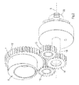
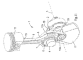
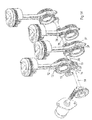
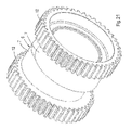
- Fig. 1 shows a part of an embodiment of a reciprocating piston mechanism 1 according to the invention, which is suitable for an internal combustion engine.
- the reciprocating piston mechanism 1 comprises a crankcase 15, which supports a crankshaft 2 by crankshaft bearings 3, see Figs. 4 and 5 .
- the crankshaft 2 includes a crankpin 4 and is rotatable with respect to the crankcase 15 about a crankshaft axis 5.
- the reciprocating piston mechanism 1 comprises a crank member 6 which is rotatably mounted on the crankpin 4.
- the crank member 6 is provided with a bearing portion 7 which is disposed eccentrically with respect to the crankpin 4, see Fig. 2 .
- the bearing portion 7 has an outer circumferential wall which bears a big end 8 of a connecting rod 9.
- the connecting rod 9 is rotatably mounted on the crank member 6 via its big end 8.
- the connecting rod 9 also includes a small end 10 to which a piston 11 is rotatably connected.
- Figs. 2 and 3 show a part of the embodiment of Fig. 1 as seen from different sides.
- the crankshaft 2 and connecting rod 9 are not shown for clarity reasons.
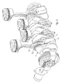
- Figs. 4 and 5 show the same part, but including the crankshaft 2.
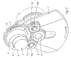
- the crank member 6 is provided with a crank member gear 12 which meshes with two intermediate gears 13.
- the crank member 6 and the crank member gear 12 may be made of one piece, but the crank member gear 12 may be pressed onto a cylindrical base part of the crank member 6, as well.
- the intermediate gears 13 are rotatably mounted to the crankshaft 2 and their axes of rotation extend parallel to the crankshaft axis 5.
- Each of the intermediate gears 13 also meshes with an auxiliary gear 14.
- the auxiliary gear 14 is fixed to an auxiliary shaft 16.
- the auxiliary shaft 16 extends concentrically through the crankshaft 2 and is rotatable with respect to the crankshaft 2 about the crankshaft axis 5.
- the auxiliary shaft 16 is rotatable about an auxiliary shaft axis which substantially coincides with the crankshaft axis 5.
- the centre line of the auxiliary gear 14 coincides with the crankshaft axis 5.
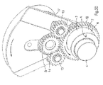
- Figs. 1 , 4 and 5 show that the auxiliary gear 14, the intermediate gears 13 and the crank member gear 12 are mounted at the same side of a crank arm 17 of the crankshaft 2. This can also be seen in the side view of Fig. 9 .
- the crank arm 17 and the adjacent crankshaft bearing 3 are integrated such that the auxiliary shaft 16 extends through both.
- the auxiliary shaft 16 extends within an outer circumference of the crankshaft bearing 3.
- the intermediate gears 13 are disposed at a side of the crankshaft 2 where a counterweight is located which creates a compact structure.
- crank member gear 12 the intermediate gears 13 and the auxiliary gears 14 may be external gears. Due to this configuration the reciprocating piston mechanism 1 can be built in a compact way and is simpler than those known in the art.
- the gear dimensions can be selected such that under operating conditions the crank member 6 rotates in the same direction as the crankshaft 2 and at half speed thereof.
- the direction of rotation is defined with respect to the crankcase.
- the directions and speeds of rotation are achieved when the gear ratio between the crank member gear 12 and the auxiliary gear 14 is two and the auxiliary shaft 16 is hold at a constant angular position with respect to the crankcase 15.
- the intermediate gears 13 and the auxiliary gear 14 are located at the same side of the crank arm 17 since in practice the diameter of the auxiliary gear 14 is relatively small, which would lead to a small diameter of the crankshaft 2 at the location of the auxiliary gear 14 if this was mounted rotatably on the crankshaft 2 at the opposite side of the crank arm 17.
- a function of the intermediate gears 13 is to turn the auxiliary gear 14 in the correct direction of rotation in case of applying a gear transmission between the crank member 6 and the auxiliary shaft 16.
- the number of teeth of the intermediate gears 13 is not relevant for the transmission ratio between the crank member gear 12 and the auxiliary gear 14.
- Figs. 17-20 show four different positions of the crankshaft 2 with respect to the crankcase 15.
- the crank member 6 and the auxiliary gear 14 are provided with marks A, B, see Fig. 17 .
- the direction of rotation of the crankshaft 2 and the crank member 6 with respect to the crankcase 15 are shown by respective arrows.
- Fig. 17 shows the position of top dead centre. In the position as shown in Fig. 18 the crankshaft 2 has rotated anti clockwise by 180° with respect to the crankcase.
- the auxiliary gear 14 has maintained its angular position whereas the crank member gear 12 has also rotated anti clockwise with respect to the crankcase 15, but by an angle of 90°.
- Figs. 19 and 20 show further steps of rotation of the crankshaft 2 by steps of 180°.
- Figs. 17-20 show that two full rotations of the crankshaft 2 corresponds to one full rotation of the crank member 6, as defined with respect to the crankcase 2.
- the reciprocating piston mechanism 1 as shown in Figs. 1-5 provides the opportunity to adjust the top dead centre of the piston 11, hence its compression ratio, by changing the angular position of the auxiliary shaft 16 with respect to the crankcase 15.
- the mechanism 1 is provided with a torsion spring 18 which is fixed to the auxiliary shaft 16, on the one hand, and to the crankcase 15, on the other hand.
- a control ring 19 is attached to the auxiliary shaft 16, for example by means of pressing, and provided with recesses 20 which are located at mutual angular distances about the crankshaft axis 5.
- the mechanism 1 also comprises an actuator 21 which controls a pin (not shown) that fits in each of the recesses 20. Under stable running conditions the pin holds the control ring 19 at a fixed position with respect to the crankcase 15 and the mechanism 1 runs at a fixed compression ratio.
- auxiliary shaft 16 may vibrate in rotational direction due to the presence of the torsion spring 18, which vibration is initiated by varying combustion forces in case of an internal combustion.
- the average angular position of the auxiliary shaft 16 is then determined by a natural balance between the actual load of the auxiliary shaft 16 on the torsion spring 18 and the actual spring force of the torsion spring 18 on the auxiliary shaft 16.
- the action and reaction force between the auxiliary shaft 16 and the torsion spring 18, i.e. the natural balance lies at a higher level.
- the embodiment as shown in Fig. 3 works as follows. If a different compression ratio is desired the pin is retracted out of the corresponding recess 20 by the actuator 21 at a predetermined engine load. For example, if a lower compression ratio is desired the actual relatively high rotational force of the auxiliary shaft 16 on the torsion spring 18 exceeds the spring force of the torsion spring 18, causing the auxiliary shaft 16 including the control ring 19 to turn in the direction of the resultant force. If the pin is displaced back towards the control ring 19 the pin fits into another recess 20. If the control ring 19 should be turned in the opposite direction in order to obtain a higher compression ratio, i.e.
- the actual rotational force of the auxiliary shaft 16 on the spring 22 at the corresponding relatively low engine load is smaller than the spring force of the torsion spring 18, hence turning the control ring 19 to the opposite direction.
- the control ring 19 can then be fixed with respect to the crankcase 15 by means of inserting the pin into the corresponding recess 20.
- the actuator 21 may be controlled electrically, hydraulically or the like.
- the circumferential surface of the control ring 19 may be part of a bearing in order to support the control ring 19 by the crankcase 15.
- the crankcase 15 may bear the control ring 19 by means of a ball bearing 19a, see Fig. 10 , but alternative bearings are conceivable.
- the angular position of the auxiliary shaft 16 is monitored by a sensor 22, which may be a simple potentiometer.
- the sensor is mounted to the crankcase 15.
- the signal from the sensor 22 is an indication of the actual compression ratio.
- crank member gear 12 and the auxiliary gear 14 are located next to each other within the same plane.
- Most piston mechanisms have piston strokes, which may not allow the configuration as shown in Figs. 1-5 .
- the intermediate gears 13 may be lengthened such that they extend beyond the crank member gear 12 in at least one direction thereof, whereas the auxiliary gear 14 meshes with the intermediate gears 13 at the extended portions thereof such that the auxiliary gear 14 partly overlaps the crank member gear 12.
- Fig. 6 where the auxiliary gear 14 is located in front of the crank member gear 12.
- the sum of the outer diameters of the crank member gear 12 and the auxiliary gear 14 is larger than a piston stroke, whereas the gears 12-14 are located at the same side of the crank arm 17.
- crank member 6 comprises a second crank member gear 12' for driving further crank members in case of a multi-cylinder reciprocating piston mechanism.
- the crank member gear 12 and the second crank member gear 12' are located at opposite end portions of the crank member 6.
- the big end 8 of the connecting rod 9 is disposed between the crank member gear 12 and the second crank member gear 12'.
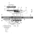
- Figs. 13-16 show an embodiment of a multi-cylinder internal combustion engines in which the second crank member gear 12' drives crank member gears that are provided at other crank pins.
- the second crank member gear 12' meshes with a further auxiliary gear 34 which is fixed to a shaft 35 that extends through an adjacent crank arm 17' and/or crank arms and/or main bearings, and on which shaft 35 another auxiliary gear 36 is fixed which drives a further crank member gear 37 of an adjacent crank pin.
- Figs. 6 and 13-16 show that the width of the crank member gear 12 is smaller than that of the second crank member gear 12'. This is possible since the crank member gear 12 meshes with two intermediate gears 13, whereas the second crank member gear 12' meshes with only one further auxiliary gear 34.
- the diameter of the crank member gear 12 that meshes with the intermediate gears 13 may be different from the diameter of the second crank member gear 12' and the further crank member gears 37. This may be desired for packaging reasons at the crank arm 17. In such a case a relative small crank member gear 12 may be pressed onto the cylindrical base part of the crank member 6. In respect of the second crank member gear 12' and the further crank member gears 37 and the other auxiliary gears 36 it is relevant that identical transmission ratios are applied.
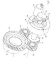
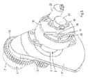
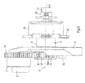
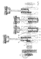
- Figs. 7 and 8 show a drive means of the auxiliary gear 14 for adjusting the compression ratio of the mechanism 1 in a continuous manner instead of by means of discrete steps as described in relation to the embodiment that is shown in Figs. 3 and 5 .
- the alternative drive means comprises an actuator 23 in the form of an electric motor, which is able to drive the auxiliary gear 14 via a worm 24 and worm gear 25 which is fixed to the auxiliary shaft 16, but other alternative drive means are conceivable.
- the worm 24 Upon rotation of the worm 24 the top and bottom dead centre of the piston 11 can be influenced.
- the torsion spring 18 could be omitted.
- the torsion spring 18 may be appropriate in order to balance the actual force of the worm gear 25 onto the worm 24, hence requiring relatively limited power to drive the worm 24.
- the actual force of the worm gear 25 onto the worm 24 may be caused by combustion forces in case of an internal combustion engine.
- An advantage of applying a drive means including the worm 24 is that it provides the opportunity to determine the actual rotational force of the auxiliary shaft 16 on the worm 24. In case of an internal combustion engine this force is directly related to combustion pressure on the piston 11.
- the force may be measured by a force or pressure sensor at the worm 24, for example a piezo electric element or the like.
- the sensor may be incorporated in the bearings of the worm 24.
- the signal may be used for misfire detection, for example.
- auxiliary shaft 16 provides the opportunity to measure combustion forces in alternative manners, for example by means of measuring torque of the auxiliary shaft 16.
- Figs. 7 and 8 also show transfer members for driving auxiliary parts in case of an internal combustion engine. Both embodiments in Figs. 7 and 8 have a power take-off gear 26 which is attached to the crankshaft 2.
- the power take-off gear 26 meshes with a first drive gear 27, for example for driving an oil pump, and a second drive gear 28, for example for driving a camshaft.
- the embodiment of Fig. 7 shows that the second drive gear 28 is mounted on a common axis with a sprocket wheel 29 for driving a chain.
- the embodiment of Fig. 8 shows that the second drive gear 28 is mounted on a common axis with a pulley 30 for driving a belt.
- the pulley 30 or sprocket wheel 29 may be replaced by a wheel for driving a toothed belt. Since the pulley 30 and the sprocket 29 are located on a shaft that extends parallel to the crankshaft 2 the mechanism 1 can be built compact in the longitudinal direction of the crankshaft 2, despite the presence of parts of the drive means for turning the auxiliary gear 14 at the end of the crankshaft 2.
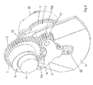
- Fig. 9 shows a side view of the embodiment as shown in Figs. 4 and 5 . It can be seen that the gears 12-14 are partly located in a recess of the crank arm 17. This provides the opportunity to minimize the length of the mechanism 1 as seen along the crankshaft 2.
- Fig. 10 shows a side view of the embodiment as shown in Fig. 7 . It can be seen that in this embodiment the gears 12-14 are not located within a common plane as explained in relation to the embodiment of Fig. 6 .
- the auxiliary gear 14 partly overlaps the crank member gear 12 as seen in a direction along their centre lines.
- the intermediate gears 13 are rotatably mounted to the crank arm 17 of the crankshaft 2.
- the intermediate gears 13 are rotatable to respective intermediate shafts 13a via plain bearings, needle bearings or the like (not shown), which intermediate shafts 13a are pressed in a bracket 31.
- the intermediate shafts 13a fit in respective holes in the crank arm 17.
- the intermediate gears 13a are mounted onto the intermediate shafts 13a, after which the bracket 31 is pressed onto the intermediate shafts 13a and fixed to the crank arm 17 through a bolt 32.
- the bracket 31 also prevents displacement of the auxiliary gear 14 in a direction away from the crank arm 17.
- Figs. 11 and 12 show an alternative embodiment of the mechanism 1 according to the invention. Parts that are similar to those in the embodiments as described hereinbefore are indicated by corresponding reference signs.
- the crank member gear 12 and the auxiliary gear 14 are replaced by respective wheels 12a and 14a for driving a toothed belt 33.
- This transmission may also be an alternative belt or a combination of sprocket wheels and a chain.
- Fig. 21 shows an alternative crank member 6 which is suitable for a reciprocating piston mechanism having a V arrangement, for example a V-engine.
- the crank member 6 comprises two crank member gears 12. Furthermore, the crank member 6 is provided with two bearing portions 7, which are angled with respect to each other about the centreline of the crank member 6. Due to this configuration the corresponding pistons reach their respective top dead centres at different angles of the crankshaft.
- the invention provides a relatively simple reciprocating piston mechanism which provides the possibility of designing a compact embodiment of the mechanism.
- the reciprocating piston mechanism may be extended to larger mechanisms having more pistons than the embodiments as described hereinbefore.
- the crank member may be cylindrical instead of eccentrical, which appears to result in lower friction losses than in a conventional mechanism having no crank member and gear transmission for driving the crank member.
Landscapes
- Engineering & Computer Science (AREA)
- General Engineering & Computer Science (AREA)
- Mechanical Engineering (AREA)
- Chemical & Material Sciences (AREA)
- Combustion & Propulsion (AREA)
- Shafts, Cranks, Connecting Bars, And Related Bearings (AREA)
- Transmission Devices (AREA)
Priority Applications (10)
| Application Number | Priority Date | Filing Date | Title |
|---|---|---|---|
| EP12152309.6A EP2620614B1 (en) | 2012-01-24 | 2012-01-24 | A reciprocating piston mechanism |
| BR112014017873-9A BR112014017873B1 (pt) | 2012-01-24 | 2013-01-24 | Mecanismo de pistão alternativo |
| RU2014129394A RU2623136C2 (ru) | 2012-01-24 | 2013-01-24 | Поршневое устройство с возвратно-поступательным движением |
| CA2861277A CA2861277C (en) | 2012-01-24 | 2013-01-24 | A reciprocating piston mechanism |
| JP2014552664A JP6305347B2 (ja) | 2012-01-24 | 2013-01-24 | 往復動ピストン機構 |
| PCT/EP2013/051333 WO2013110700A1 (en) | 2012-01-24 | 2013-01-24 | A reciprocating piston mechanism |
| EP13701256.3A EP2828501A1 (en) | 2012-01-24 | 2013-01-24 | A reciprocating piston mechanism |
| US14/373,470 US10234006B2 (en) | 2012-01-24 | 2013-01-24 | Reciprocating piston mechanism |
| KR1020147023200A KR102074649B1 (ko) | 2012-01-24 | 2013-01-24 | 왕복 피스톤 기구 |
| CN201380009329.8A CN104204455B (zh) | 2012-01-24 | 2013-01-24 | 一种往复活塞机构 |
Applications Claiming Priority (1)
| Application Number | Priority Date | Filing Date | Title |
|---|---|---|---|
| EP12152309.6A EP2620614B1 (en) | 2012-01-24 | 2012-01-24 | A reciprocating piston mechanism |
Publications (2)
| Publication Number | Publication Date |
|---|---|
| EP2620614A1 EP2620614A1 (en) | 2013-07-31 |
| EP2620614B1 true EP2620614B1 (en) | 2016-11-09 |
Family
ID=47603746
Family Applications (2)
| Application Number | Title | Priority Date | Filing Date |
|---|---|---|---|
| EP12152309.6A Active EP2620614B1 (en) | 2012-01-24 | 2012-01-24 | A reciprocating piston mechanism |
| EP13701256.3A Withdrawn EP2828501A1 (en) | 2012-01-24 | 2013-01-24 | A reciprocating piston mechanism |
Family Applications After (1)
| Application Number | Title | Priority Date | Filing Date |
|---|---|---|---|
| EP13701256.3A Withdrawn EP2828501A1 (en) | 2012-01-24 | 2013-01-24 | A reciprocating piston mechanism |
Country Status (9)
| Country | Link |
|---|---|
| US (1) | US10234006B2 (https=) |
| EP (2) | EP2620614B1 (https=) |
| JP (1) | JP6305347B2 (https=) |
| KR (1) | KR102074649B1 (https=) |
| CN (1) | CN104204455B (https=) |
| BR (1) | BR112014017873B1 (https=) |
| CA (1) | CA2861277C (https=) |
| RU (1) | RU2623136C2 (https=) |
| WO (1) | WO2013110700A1 (https=) |
Families Citing this family (49)
| Publication number | Priority date | Publication date | Assignee | Title |
|---|---|---|---|---|
| WO2011006537A1 (en) * | 2009-07-15 | 2011-01-20 | Sleper, Joannes, Jacobus, Josephus | A reciprocating piston mechanism |
| EP2620614B1 (en) | 2012-01-24 | 2016-11-09 | Gomecsys B.V. | A reciprocating piston mechanism |
| EP2873834A1 (en) * | 2013-11-13 | 2015-05-20 | Gomecsys B.V. | A method of assembling and an assembly of a crankshaft and a crank member |
| EP2902603A1 (en) * | 2014-01-31 | 2015-08-05 | Gomecsys B.V. | An internal combustion engine including variable compression ratio |
| EP2905449B1 (en) | 2014-02-11 | 2018-05-09 | Gomecsys B.V. | An internal combustion engine including variable compression ratio and a method of operating the engine |
| EP2907986B1 (en) | 2014-02-18 | 2017-05-03 | Gomecsys B.V. | A four-stroke internal combustion engine with variable compression ratio |
| EP2930329B1 (en) * | 2014-04-08 | 2016-12-28 | Gomecsys B.V. | An internal combustion engine including variable compression ratio |
| FR3022299A1 (fr) * | 2014-06-12 | 2015-12-18 | Peugeot Citroen Automobiles Sa | Moteur thermique a combustion interne a taux de compression variable |
| DE102014216533A1 (de) | 2014-08-20 | 2016-02-25 | Schaeffler Technologies AG & Co. KG | Vorrichtung zur Veränderung eines Verdichtungsverhältnisses einer Zylindereinheit einer Hubkolbenbrennkraftmaschine |
| CN104832279B (zh) * | 2015-01-08 | 2018-01-02 | 武汉富国发动机科技有限公司 | 新型的节能内燃机 |
| FR3035681B1 (fr) * | 2015-04-28 | 2017-04-28 | Peugeot Citroen Automobiles Sa | Piece excentrique pour systeme de variation du taux de compression d'un moteur thermique |
| FR3035682B1 (fr) * | 2015-04-28 | 2017-04-28 | Peugeot Citroen Automobiles Sa | Moteur a combustion interne de vehicule automobile muni d'un systeme de variation du taux de compression |
| FR3036146B1 (fr) * | 2015-05-11 | 2017-05-26 | Peugeot Citroen Automobiles Sa | Piece excentrique pour systeme de variation du taux de compression d'un moteur thermique |
| EP3103986B1 (en) | 2015-06-08 | 2018-01-31 | Gomecsys B.V. | A four-stroke internal combustion engine including variable compression ratio and a vehicle |
| JP6489217B2 (ja) * | 2015-07-21 | 2019-03-27 | 日産自動車株式会社 | 内燃機関 |
| CN105156620B (zh) * | 2015-07-24 | 2018-04-17 | 李云峰 | 一种往复‑旋转运动转换机构 |
| DE102015112690B4 (de) * | 2015-08-03 | 2023-04-20 | Ovalo Gmbh | Aktuatorsystem, insbesondere zum Ankoppeln an die Verstellwelle eines Verbrennungsmotors zum Einstellen des Expansionshubes und/oder des Verdichtungsverhältnisses |
| FR3042815B1 (fr) * | 2015-10-22 | 2019-08-02 | Psa Automobiles Sa. | Moteur thermique muni d'un systeme de variation du taux de compression |
| FR3042816B1 (fr) | 2015-10-22 | 2017-12-08 | Peugeot Citroen Automobiles Sa | Moteur thermique muni d'un systeme de variation du taux de compression |
| FR3043720B1 (fr) | 2015-11-17 | 2019-11-08 | MCE 5 Development | Moteur a rapport volumetrique variable |
| CN105605081A (zh) * | 2016-03-18 | 2016-05-25 | 蔡建龙 | 一种发动机曲轴 |
| CN105673795A (zh) * | 2016-03-23 | 2016-06-15 | 刘有双 | 一种加速器 |
| FR3050234B1 (fr) * | 2016-04-19 | 2021-01-15 | Peugeot Citroen Automobiles Sa | Ensemble pour systeme de variation de taux de compression de moteur thermique |
| FR3052495B1 (fr) | 2016-06-09 | 2020-01-10 | Peugeot Citroen Automobiles Sa | Moteur thermique muni d'un systeme de variation du taux de compression ameliore |
| US10119463B2 (en) * | 2016-12-09 | 2018-11-06 | Mark Albert Sokalski | Infinitely variable compression ratio and single stroke length mechanism or dual stroke length mechanism of reciprocating 2-cycle or 4-cycle internal combustion engine |
| JP2018105159A (ja) * | 2016-12-22 | 2018-07-05 | いすゞ自動車株式会社 | エンジン |
| DE102017200918B4 (de) | 2017-01-20 | 2022-10-06 | Bayerische Motoren Werke Aktiengesellschaft | Kurbeltrieb für eine Hubkolben-Brennkraftmaschine |
| JP7101459B2 (ja) * | 2017-04-26 | 2022-07-15 | Ntn株式会社 | 電動アクチュエータ |
| US10801591B2 (en) * | 2017-06-23 | 2020-10-13 | Crown Packaging Technology, Inc. | System and method for converting rotating motion into linear motion |
| DE102018201988B3 (de) | 2018-02-08 | 2019-05-29 | Audi Ag | Pleuelstange für eine Brennkraftmaschine sowie entsprechende Brennkraftmaschine |
| EP3540270A1 (en) | 2018-03-12 | 2019-09-18 | Gomecsys B.V. | A gear train and an internal combustion engine |
| EP3608523A1 (en) * | 2018-08-09 | 2020-02-12 | Gomecsys B.V. | An eccentric member and a v-type internal combustion engine |
| DE102018128524B4 (de) | 2018-11-14 | 2022-09-22 | Bayerische Motoren Werke Aktiengesellschaft | Vorrichtung zum Verändern eines Kompressionsverhältnisses, Hubkolbenbrennkraftmaschine und Arbeitsvorrichtung |
| EP3719339A1 (en) | 2019-04-05 | 2020-10-07 | Gomecsys B.V. | An apparatus including an adjusting system for adjusting a rotational position of a shaft with respect to a shaft holding member |
| EP3726023A1 (en) | 2019-04-17 | 2020-10-21 | Gomecsys B.V. | An internal combustion engine |
| RU2716521C1 (ru) * | 2019-07-30 | 2020-03-12 | Общество с ограниченной ответственностью "Завод дозировочной техники "Ареопаг" | Поршневое устройство насоса |
| EP3808955A1 (en) | 2019-10-15 | 2021-04-21 | Gomecsys B.V. | An internal combustion engine with variable compression ratio |
| CN111022603B (zh) * | 2020-01-07 | 2021-07-20 | 重庆大学 | 交错式行星滚柱丝杠减速器 |
| US11131240B1 (en) * | 2020-05-15 | 2021-09-28 | GM Global Technology Operations LLC | Engine assembly including a force splitter for varying compression ratio using an actuator |
| GEP20227367B (en) * | 2020-08-06 | 2022-03-25 | Ramzan Goytemirov | Engine having compression ratio control mechanism |
| CN112504054A (zh) * | 2020-11-24 | 2021-03-16 | 重庆钧顶机械制造有限公司 | 一种曲柄连杆机构用正时齿轮啮合跳动度检具 |
| DE102021103790A1 (de) | 2021-02-18 | 2022-08-18 | Bayerische Motoren Werke Aktiengesellschaft | Verstelleinrichtung zum Einstellen eines variablen Verdichtungsverhältnisses eines Hubkolbenmotors, Kraftfahrzeug sowie Verfahren |
| US11255374B1 (en) * | 2021-03-04 | 2022-02-22 | VenTec LLC | Engine crank |
| EP4086443A1 (en) | 2021-05-05 | 2022-11-09 | Gomecsys B.V. | An internal combustion engine and a method of operating the internal combustion engine |
| US20260009350A1 (en) * | 2023-10-23 | 2026-01-08 | Jesse REED | Piston System For a Compression Engine |
| EP4671514A1 (en) | 2024-06-24 | 2025-12-31 | Gomecsys B.V. | INTERNAL COMBUSTION ENGINE AND CAGE |
| EP4707556A1 (en) | 2024-09-05 | 2026-03-11 | Gomecsys B.V. | A crankshaft and an internal combustion engine including variable compression ratio |
| WO2026052556A1 (en) | 2024-09-05 | 2026-03-12 | Gomecsys B.V. | A crankshaft, an internal combustion engine including variable compression ratio and a method of assembling the crankshaft |
| EP4707555A1 (en) | 2024-09-05 | 2026-03-11 | Gomecsys B.V. | A crankshaft and an internal combustion engine including variable compression ratio |
Family Cites Families (79)
| Publication number | Priority date | Publication date | Assignee | Title |
|---|---|---|---|---|
| DD242077A (https=) * | ||||
| US460642A (en) * | 1891-10-06 | Variable crank-motion | ||
| FR636243A (https=) * | 1928-04-04 | |||
| DE181913C (https=) | ||||
| DE164819C (https=) * | 1904-08-02 | 1905-11-16 | ||
| US1207429A (en) * | 1916-01-04 | 1916-12-05 | James Currie Morison | Means for equalizing piston displacement. |
| GB150291A (en) * | 1917-12-13 | 1921-11-18 | Clerget Blin & Cie | Improvements in or relating to explosion engines with variable compression |
| DE329861C (de) * | 1918-04-12 | 1920-12-04 | Motorenfabrik Oberursel A G | Hoehenreglung fuer Umlaufmotoren von Luftfahrzeugen |
| GB173252A (en) | 1920-07-19 | 1921-12-19 | Charles Kane Salisbury | Improvements in internal combustion engines |
| US1553009A (en) | 1923-07-23 | 1925-09-08 | Stuke Ernest | Engine |
| DE488059C (de) | 1925-05-16 | 1929-12-18 | Louis Damblanc | Brennkraftmaschine mit veraenderlichem Kolbenhub |
| US1767352A (en) | 1927-03-26 | 1930-06-24 | Damblanc Louis | Crank shaft |
| US1964096A (en) * | 1931-11-21 | 1934-06-26 | Emmitt M Tucker | Connecting rod mounting |
| FR861611A (fr) | 1939-07-29 | 1941-02-13 | Moteur à explosion à cylindrée et taux de compression variables automatique | |
| US2271766A (en) | 1940-05-06 | 1942-02-03 | Harry A Huebotter | Engine |
| US2369747A (en) * | 1942-07-30 | 1945-02-20 | Elvin R Munn | Engine |
| FR986605A (fr) * | 1943-11-23 | 1951-08-02 | Dispositif de variation, en marche, du rapport volumétrique d'un moteur | |
| FR1014314A (fr) | 1946-04-10 | 1952-08-13 | Moteur à explosion à cylindrée variable | |
| GB1094649A (en) | 1963-12-16 | 1967-12-13 | Henry Eddington Roberts | Improvements in or relating to machines having a reciprocating member coupled to a rotatable member |
| US3686972A (en) * | 1970-05-28 | 1972-08-29 | Edward M Mcwhorter | Internal combustion engine variable throw crankshaft |
| JPS5247093B2 (https=) * | 1972-05-10 | 1977-11-30 | ||
| US3861239A (en) * | 1972-06-05 | 1975-01-21 | Edward M Mcwhorter | Internal combustion engine combustion control crankshaft |
| US3886805A (en) * | 1974-04-09 | 1975-06-03 | Ivan Koderman | Crank gear for the conversion of a translational motion into rotation |
| US4152955A (en) * | 1975-01-02 | 1979-05-08 | Mcwhorter Edward M | Engine compound crankshaft |
| US4073196A (en) * | 1976-08-13 | 1978-02-14 | Gilbert T. Hendren, Jr. | Cranking system of varying radius |
| DE2720284C3 (de) | 1977-05-05 | 1981-05-27 | Huf, Franz, Prof. Dipl.-Ing., 7750 Konstanz | Schubkurbelsystem-Baureihe |
| US4179942A (en) * | 1978-01-09 | 1979-12-25 | Matthews Leslie C | Variable ratio crank assembly |
| DE2947882A1 (de) | 1979-11-28 | 1981-07-23 | Volkswagenwerk Ag, 3180 Wolfsburg | Pleuelloser kurbeltrieb fuer eine hubkolbenmaschine |
| AU7857681A (en) | 1980-12-16 | 1982-06-24 | Charles Radcliff Furlonger | Internal combustion engine |
| JPH0627969B2 (ja) | 1984-06-29 | 1994-04-13 | キヤノン株式会社 | 文字処理装置 |
| PL144411B1 (en) * | 1984-11-23 | 1988-05-31 | Politechnika Warszawska | Crank mechanism with variable crank radius for a piston-type internal combustion engine |
| JPS61187931A (ja) | 1985-02-18 | 1986-08-21 | Asahi Chem Ind Co Ltd | 水溶液中の砒素の吸着剤 |
| EP0222841A1 (en) | 1985-05-24 | 1987-05-27 | COOPER, Robert Alan | Crankshaft crank |
| JPH0443620Y2 (https=) * | 1985-12-28 | 1992-10-15 | ||
| DE3634536A1 (de) | 1986-10-10 | 1987-02-19 | Toan Dat Tran | Kurbeltrieb mit doppelten kolbenhueben |
| DE3642681A1 (de) | 1986-12-13 | 1988-06-23 | Michael Schenk | Kurbelwelle, insbesondere fuer hubkolben-verbrennungsmaschinen |
| US4860702A (en) | 1988-03-21 | 1989-08-29 | Doundoulakis George J | Compression ratio control in reciprocating piston engines |
| EP0345366A1 (en) | 1988-06-08 | 1989-12-13 | Alfredo Buffoli | Eight cycle or diesel type internal combustion engine |
| JPH0361135A (ja) | 1989-07-31 | 1991-03-15 | Masateru Maruyama | 自動車、船などの乗物の操作部スイッチと接続する信号表示体とその信号表示体への意志信号の伝達方法 |
| JPH0422717A (ja) * | 1990-05-17 | 1992-01-27 | Mitsubishi Motors Corp | 内燃エンジンの可変圧縮比機構 |
| GB2258271A (en) * | 1991-08-01 | 1993-02-03 | Ford Motor Co | Variable compression ratio i.c.engine. |
| FR2680402A1 (fr) | 1991-08-12 | 1993-02-19 | Bes Jean Paul | Mecanisme de transformation reversible d'un mouvement de rotation uniforme en un mouvement rectiligne alternatif sinusouidal a course variable, et moteur comportant un tel mecanisme. |
| US5133314A (en) * | 1991-12-23 | 1992-07-28 | Langstroth Steven W | Linkage arms for minimizing piston wobble |
| US5265566A (en) | 1991-12-23 | 1993-11-30 | General Motors Corporation | Assembled seal disc for a crankshaft |
| US5170757A (en) | 1991-12-24 | 1992-12-15 | Damien Gamache | Variable horsepower output gearing for piston engine |
| SE513061C2 (sv) | 1992-06-30 | 2000-06-26 | Fanja Ltd | Förfarande och anordning för ändring av kompressionsförhållandet i en förbränningsmotor |
| SE501331C2 (sv) | 1993-05-28 | 1995-01-16 | Saab Automobile | Strukturinneslutning av förbränningsmotor i syfte att reducera motorljud |
| US5482015A (en) | 1994-07-11 | 1996-01-09 | Fish; Robert D. | Device for coupling reciprocating and rotating motions |
| RU2053391C1 (ru) * | 1994-03-18 | 1996-01-27 | Евгений Иванович Воронкин | Двигатель внутреннего сгорания с продленным тактом рабочего хода |
| AU699252B2 (en) | 1995-02-28 | 1998-11-26 | Tk Design Ag | Reciprocating piston type internal combustion engine with variable compression ratio |
| GB9611135D0 (en) | 1996-05-29 | 1996-07-31 | Gang Nail Systems Limited | Connector |
| JP2829287B2 (ja) | 1996-10-23 | 1998-11-25 | ロングウェルジャパン株式会社 | クランク装置 |
| AUPO885297A0 (en) * | 1997-09-01 | 1997-09-25 | Bresland, Claude Neil | Compression engine |
| US5927236A (en) * | 1997-10-28 | 1999-07-27 | Gonzalez; Luis Marino | Variable stroke mechanism for internal combustion engine |
| NL1009211C2 (nl) * | 1998-05-19 | 1999-11-22 | L H De Gooijer Holding B V | Kruk-drijfstangmechanisme. |
| US6453869B1 (en) * | 2001-01-04 | 2002-09-24 | Mooremac, Llc | Internal combustion engine with variable ratio crankshaft assembly |
| CA2435728C (en) | 2001-01-24 | 2008-12-23 | Hasan Basri Ozdamar | Motor with rotary connecting rod bolt |
| ITRM20010038A1 (it) | 2001-01-26 | 2002-07-26 | Foggia Andrea Di | Dispositivo per la trasformazione del moto rettilineo alternato in unmoto rotatorio e viceversa, dotato di uno o piu' satelliti montati a s |
| JP2002286020A (ja) | 2001-03-26 | 2002-10-03 | Shinko Denki:Kk | 往復運動機関のクランク機構 |
| US20030183026A1 (en) | 2002-03-29 | 2003-10-02 | Korniyenko Alexsandr Y. | Apparatus for converting rotary to reciprocating motion and vice versa |
| AU2003229184A1 (en) | 2002-05-17 | 2003-12-02 | Normand Beaudoin | Retro-mechanical, post-mechanical, bi-mechanical traction engines |
| DE10230425A1 (de) | 2002-07-06 | 2004-01-22 | Bayerische Motoren Werke Ag | Lagerschalenanordnung, insbesondere Exzenterschalenanordnung für einen Kurbeltrieb |
| DE10230426A1 (de) | 2002-07-06 | 2004-01-22 | Bayerische Motoren Werke Ag | Lagerschale, insbesondere exzentrische Kurbelzapfen-Lagerschale für den Kurbeltrieb einer Brennkraftmaschine |
| WO2005059330A2 (en) * | 2003-12-11 | 2005-06-30 | Dow Glendal R | Variable crankshaft |
| RU2280771C2 (ru) * | 2004-05-19 | 2006-07-27 | Владимир Александрович Ворогушин | Устройство преобразования движения |
| US7185557B2 (en) | 2004-06-29 | 2007-03-06 | Thomas Mark Venettozzi | Epitrochoidal crankshaft mechanism and method |
| JP2007113471A (ja) | 2005-10-19 | 2007-05-10 | Toyota Motor Corp | 内燃機関 |
| EP1959112A1 (en) | 2007-02-16 | 2008-08-20 | Gomecsys B.V. | A reciprocating piston mechanism, a method of assembling this, and an internal combustion engine |
| EP1983215A1 (en) | 2007-04-20 | 2008-10-22 | Gomecsys B.V. | Reciprocating piston machine and internal combustion engine |
| JP2009036030A (ja) | 2007-07-31 | 2009-02-19 | Fuji Heavy Ind Ltd | 高膨張比エンジンのクランクシャフト構造 |
| EP2025893A1 (en) * | 2007-08-09 | 2009-02-18 | Gomecsys B.V. | A reciprocating piston mechanism |
| US20090133653A1 (en) | 2007-11-26 | 2009-05-28 | Thomas Duzzie | Spur gear drive for an internal combustion engine |
| US8001948B2 (en) | 2008-01-30 | 2011-08-23 | Chuy-Nan Chio | Kinetic energy generation apparatus having increased power output |
| WO2009100759A1 (en) | 2008-02-13 | 2009-08-20 | Gomecsys B.V. | A reciprocating piston mechanism and a method of increasing internal egr in an internal combustion engine |
| WO2011006537A1 (en) | 2009-07-15 | 2011-01-20 | Sleper, Joannes, Jacobus, Josephus | A reciprocating piston mechanism |
| DE102011085647A1 (de) | 2011-11-03 | 2013-05-08 | Bayerische Motoren Werke Aktiengesellschaft | Geteilte Lagerschale und Verfahren zur Herstellung einer geteilten Lagerschale |
| EP2620614B1 (en) | 2012-01-24 | 2016-11-09 | Gomecsys B.V. | A reciprocating piston mechanism |
| WO2013160501A1 (es) | 2012-04-23 | 2013-10-31 | Garcia Sanchez Eduardo | Cadena cinemática para posicionar unos cojinetes excéntricos que giran sobre las muñequillas del cigüeñal de un motor de relación de compresión variable. |
| WO2014005258A1 (en) | 2012-07-02 | 2014-01-09 | Qualcomm Incorporated | Methods and apparatuses for enabling fast early termination of voice frames on the uplink |
-
2012
- 2012-01-24 EP EP12152309.6A patent/EP2620614B1/en active Active
-
2013
- 2013-01-24 CN CN201380009329.8A patent/CN104204455B/zh active Active
- 2013-01-24 CA CA2861277A patent/CA2861277C/en active Active
- 2013-01-24 WO PCT/EP2013/051333 patent/WO2013110700A1/en not_active Ceased
- 2013-01-24 JP JP2014552664A patent/JP6305347B2/ja active Active
- 2013-01-24 KR KR1020147023200A patent/KR102074649B1/ko active Active
- 2013-01-24 BR BR112014017873-9A patent/BR112014017873B1/pt active IP Right Grant
- 2013-01-24 EP EP13701256.3A patent/EP2828501A1/en not_active Withdrawn
- 2013-01-24 RU RU2014129394A patent/RU2623136C2/ru active
- 2013-01-24 US US14/373,470 patent/US10234006B2/en active Active
Also Published As
| Publication number | Publication date |
|---|---|
| JP6305347B2 (ja) | 2018-04-04 |
| CN104204455A (zh) | 2014-12-10 |
| JP2015508470A (ja) | 2015-03-19 |
| CN104204455B (zh) | 2018-03-27 |
| RU2623136C2 (ru) | 2017-06-22 |
| BR112014017873A8 (pt) | 2017-07-11 |
| CA2861277C (en) | 2020-06-16 |
| EP2620614A1 (en) | 2013-07-31 |
| US10234006B2 (en) | 2019-03-19 |
| KR102074649B1 (ko) | 2020-03-02 |
| BR112014017873B1 (pt) | 2022-10-18 |
| BR112014017873A2 (https=) | 2017-06-20 |
| RU2014129394A (ru) | 2016-03-20 |
| CA2861277A1 (en) | 2013-08-01 |
| KR20140113737A (ko) | 2014-09-24 |
| WO2013110700A1 (en) | 2013-08-01 |
| US20140360292A1 (en) | 2014-12-11 |
| EP2828501A1 (en) | 2015-01-28 |
Similar Documents
| Publication | Publication Date | Title |
|---|---|---|
| EP2620614B1 (en) | A reciprocating piston mechanism | |
| EP2257700B1 (en) | A reciprocating piston mechanism and a method of increasing internal egr in an internal combustion engine | |
| EP2454458B1 (en) | A reciprocating piston mechanism | |
| US6588384B2 (en) | Apparatus for varying the compression ratio of an internal-combustion engine | |
| JP4605907B2 (ja) | 前後で同軸にかつ互いに横方向間隔をおいて配置された軸線平行な2本の軸を連結する連結要素 | |
| EP2025893A1 (en) | A reciprocating piston mechanism | |
| WO2008129025A1 (en) | Reciprocating piston machine and internal combustion engine | |
| EP2902603A1 (en) | An internal combustion engine including variable compression ratio | |
| EP2905449B1 (en) | An internal combustion engine including variable compression ratio and a method of operating the engine | |
| WO2019154689A1 (en) | A reciprocating piston mechanism | |
| US20080108464A1 (en) | Vibration Compensating Pulley | |
| US20100190592A1 (en) | Vibration Compensating Pulley | |
| JP4741733B2 (ja) | 同軸に前後してかつ互いに軸平行に横方向間隔を置いて配置された2つの軸を連結するためのカップリング要素 | |
| WO2023094039A1 (en) | An eccentric member and an internal combustion engine | |
| WO2011110325A2 (en) | Mechanism for converting a reciprocating movement into a rotational movement and vice versa, and device comprising such a mechanism. | |
| CN105090403B (zh) | 一种自动无级变速传动装置 | |
| RU2011061C1 (ru) | Механизм уравновешивания поршневой машины | |
| CA2326705C (en) | Crank system with sinusoidal piston motion | |
| JP2016109109A (ja) | 行程容積連続可変装置 | |
| TH84789A (th) | เครื่องยนต์แปรผันระยะชัก | |
| TH27666B (th) | เครื่องยนต์แปรผันระยะชัก | |
| TH53273B (th) | เครื่องยนต์ช่วงชักแปรผัน | |
| TH99385A (th) | เครื่องยนต์ช่วงชักแปรผัน | |
| JP2011074810A (ja) | 内燃機関 |
Legal Events
| Date | Code | Title | Description |
|---|---|---|---|
| PUAI | Public reference made under article 153(3) epc to a published international application that has entered the european phase |
Free format text: ORIGINAL CODE: 0009012 |
|
| AK | Designated contracting states |
Kind code of ref document: A1 Designated state(s): AL AT BE BG CH CY CZ DE DK EE ES FI FR GB GR HR HU IE IS IT LI LT LU LV MC MK MT NL NO PL PT RO RS SE SI SK SM TR |
|
| AX | Request for extension of the european patent |
Extension state: BA ME |
|
| RAP1 | Party data changed (applicant data changed or rights of an application transferred) |
Owner name: GOMECSYS B.V. |
|
| 17P | Request for examination filed |
Effective date: 20140129 |
|
| RBV | Designated contracting states (corrected) |
Designated state(s): AL AT BE BG CH CY CZ DE DK EE ES FI FR GB GR HR HU IE IS IT LI LT LU LV MC MK MT NL NO PL PT RO RS SE SI SK SM TR |
|
| 17Q | First examination report despatched |
Effective date: 20150304 |
|
| GRAP | Despatch of communication of intention to grant a patent |
Free format text: ORIGINAL CODE: EPIDOSNIGR1 |
|
| INTG | Intention to grant announced |
Effective date: 20160530 |
|
| GRAS | Grant fee paid |
Free format text: ORIGINAL CODE: EPIDOSNIGR3 |
|
| GRAA | (expected) grant |
Free format text: ORIGINAL CODE: 0009210 |
|
| AK | Designated contracting states |
Kind code of ref document: B1 Designated state(s): AL AT BE BG CH CY CZ DE DK EE ES FI FR GB GR HR HU IE IS IT LI LT LU LV MC MK MT NL NO PL PT RO RS SE SI SK SM TR |
|
| REG | Reference to a national code |
Ref country code: GB Ref legal event code: FG4D |
|
| REG | Reference to a national code |
Ref country code: AT Ref legal event code: REF Ref document number: 844145 Country of ref document: AT Kind code of ref document: T Effective date: 20161115 Ref country code: CH Ref legal event code: EP |
|
| REG | Reference to a national code |
Ref country code: IE Ref legal event code: FG4D |
|
| REG | Reference to a national code |
Ref country code: DE Ref legal event code: R096 Ref document number: 602012025068 Country of ref document: DE |
|
| REG | Reference to a national code |
Ref country code: NL Ref legal event code: FP |
|
| REG | Reference to a national code |
Ref country code: FR Ref legal event code: PLFP Year of fee payment: 6 |
|
| REG | Reference to a national code |
Ref country code: SE Ref legal event code: TRGR |
|
| PG25 | Lapsed in a contracting state [announced via postgrant information from national office to epo] |
Ref country code: LV Free format text: LAPSE BECAUSE OF FAILURE TO SUBMIT A TRANSLATION OF THE DESCRIPTION OR TO PAY THE FEE WITHIN THE PRESCRIBED TIME-LIMIT Effective date: 20161109 |
|
| REG | Reference to a national code |
Ref country code: LT Ref legal event code: MG4D |
|
| REG | Reference to a national code |
Ref country code: AT Ref legal event code: MK05 Ref document number: 844145 Country of ref document: AT Kind code of ref document: T Effective date: 20161109 |
|
| PG25 | Lapsed in a contracting state [announced via postgrant information from national office to epo] |
Ref country code: LT Free format text: LAPSE BECAUSE OF FAILURE TO SUBMIT A TRANSLATION OF THE DESCRIPTION OR TO PAY THE FEE WITHIN THE PRESCRIBED TIME-LIMIT Effective date: 20161109 Ref country code: GR Free format text: LAPSE BECAUSE OF FAILURE TO SUBMIT A TRANSLATION OF THE DESCRIPTION OR TO PAY THE FEE WITHIN THE PRESCRIBED TIME-LIMIT Effective date: 20170210 Ref country code: NO Free format text: LAPSE BECAUSE OF FAILURE TO SUBMIT A TRANSLATION OF THE DESCRIPTION OR TO PAY THE FEE WITHIN THE PRESCRIBED TIME-LIMIT Effective date: 20170209 |
|
| PG25 | Lapsed in a contracting state [announced via postgrant information from national office to epo] |
Ref country code: PL Free format text: LAPSE BECAUSE OF FAILURE TO SUBMIT A TRANSLATION OF THE DESCRIPTION OR TO PAY THE FEE WITHIN THE PRESCRIBED TIME-LIMIT Effective date: 20161109 Ref country code: BE Free format text: LAPSE BECAUSE OF NON-PAYMENT OF DUE FEES Effective date: 20170131 Ref country code: IS Free format text: LAPSE BECAUSE OF FAILURE TO SUBMIT A TRANSLATION OF THE DESCRIPTION OR TO PAY THE FEE WITHIN THE PRESCRIBED TIME-LIMIT Effective date: 20170309 Ref country code: AT Free format text: LAPSE BECAUSE OF FAILURE TO SUBMIT A TRANSLATION OF THE DESCRIPTION OR TO PAY THE FEE WITHIN THE PRESCRIBED TIME-LIMIT Effective date: 20161109 Ref country code: PT Free format text: LAPSE BECAUSE OF FAILURE TO SUBMIT A TRANSLATION OF THE DESCRIPTION OR TO PAY THE FEE WITHIN THE PRESCRIBED TIME-LIMIT Effective date: 20170309 Ref country code: FI Free format text: LAPSE BECAUSE OF FAILURE TO SUBMIT A TRANSLATION OF THE DESCRIPTION OR TO PAY THE FEE WITHIN THE PRESCRIBED TIME-LIMIT Effective date: 20161109 Ref country code: ES Free format text: LAPSE BECAUSE OF FAILURE TO SUBMIT A TRANSLATION OF THE DESCRIPTION OR TO PAY THE FEE WITHIN THE PRESCRIBED TIME-LIMIT Effective date: 20161109 Ref country code: HR Free format text: LAPSE BECAUSE OF FAILURE TO SUBMIT A TRANSLATION OF THE DESCRIPTION OR TO PAY THE FEE WITHIN THE PRESCRIBED TIME-LIMIT Effective date: 20161109 Ref country code: RS Free format text: LAPSE BECAUSE OF FAILURE TO SUBMIT A TRANSLATION OF THE DESCRIPTION OR TO PAY THE FEE WITHIN THE PRESCRIBED TIME-LIMIT Effective date: 20161109 |
|
| PG25 | Lapsed in a contracting state [announced via postgrant information from national office to epo] |
Ref country code: CZ Free format text: LAPSE BECAUSE OF FAILURE TO SUBMIT A TRANSLATION OF THE DESCRIPTION OR TO PAY THE FEE WITHIN THE PRESCRIBED TIME-LIMIT Effective date: 20161109 Ref country code: EE Free format text: LAPSE BECAUSE OF FAILURE TO SUBMIT A TRANSLATION OF THE DESCRIPTION OR TO PAY THE FEE WITHIN THE PRESCRIBED TIME-LIMIT Effective date: 20161109 Ref country code: DK Free format text: LAPSE BECAUSE OF FAILURE TO SUBMIT A TRANSLATION OF THE DESCRIPTION OR TO PAY THE FEE WITHIN THE PRESCRIBED TIME-LIMIT Effective date: 20161109 Ref country code: SK Free format text: LAPSE BECAUSE OF FAILURE TO SUBMIT A TRANSLATION OF THE DESCRIPTION OR TO PAY THE FEE WITHIN THE PRESCRIBED TIME-LIMIT Effective date: 20161109 Ref country code: RO Free format text: LAPSE BECAUSE OF FAILURE TO SUBMIT A TRANSLATION OF THE DESCRIPTION OR TO PAY THE FEE WITHIN THE PRESCRIBED TIME-LIMIT Effective date: 20161109 |
|
| REG | Reference to a national code |
Ref country code: DE Ref legal event code: R097 Ref document number: 602012025068 Country of ref document: DE |
|
| PG25 | Lapsed in a contracting state [announced via postgrant information from national office to epo] |
Ref country code: SM Free format text: LAPSE BECAUSE OF FAILURE TO SUBMIT A TRANSLATION OF THE DESCRIPTION OR TO PAY THE FEE WITHIN THE PRESCRIBED TIME-LIMIT Effective date: 20161109 Ref country code: BG Free format text: LAPSE BECAUSE OF FAILURE TO SUBMIT A TRANSLATION OF THE DESCRIPTION OR TO PAY THE FEE WITHIN THE PRESCRIBED TIME-LIMIT Effective date: 20170209 Ref country code: BE Free format text: LAPSE BECAUSE OF FAILURE TO SUBMIT A TRANSLATION OF THE DESCRIPTION OR TO PAY THE FEE WITHIN THE PRESCRIBED TIME-LIMIT Effective date: 20161109 |
|
| REG | Reference to a national code |
Ref country code: CH Ref legal event code: PL |
|
| PLBE | No opposition filed within time limit |
Free format text: ORIGINAL CODE: 0009261 |
|
| STAA | Information on the status of an ep patent application or granted ep patent |
Free format text: STATUS: NO OPPOSITION FILED WITHIN TIME LIMIT |
|
| PG25 | Lapsed in a contracting state [announced via postgrant information from national office to epo] |
Ref country code: MC Free format text: LAPSE BECAUSE OF FAILURE TO SUBMIT A TRANSLATION OF THE DESCRIPTION OR TO PAY THE FEE WITHIN THE PRESCRIBED TIME-LIMIT Effective date: 20161109 |
|
| 26N | No opposition filed |
Effective date: 20170810 |
|
| PG25 | Lapsed in a contracting state [announced via postgrant information from national office to epo] |
Ref country code: LI Free format text: LAPSE BECAUSE OF NON-PAYMENT OF DUE FEES Effective date: 20170131 Ref country code: CH Free format text: LAPSE BECAUSE OF NON-PAYMENT OF DUE FEES Effective date: 20170131 |
|
| REG | Reference to a national code |
Ref country code: IE Ref legal event code: MM4A |
|
| PG25 | Lapsed in a contracting state [announced via postgrant information from national office to epo] |
Ref country code: SI Free format text: LAPSE BECAUSE OF FAILURE TO SUBMIT A TRANSLATION OF THE DESCRIPTION OR TO PAY THE FEE WITHIN THE PRESCRIBED TIME-LIMIT Effective date: 20161109 Ref country code: LU Free format text: LAPSE BECAUSE OF NON-PAYMENT OF DUE FEES Effective date: 20170124 |
|
| REG | Reference to a national code |
Ref country code: FR Ref legal event code: PLFP Year of fee payment: 7 |
|
| PG25 | Lapsed in a contracting state [announced via postgrant information from national office to epo] |
Ref country code: IE Free format text: LAPSE BECAUSE OF NON-PAYMENT OF DUE FEES Effective date: 20170124 |
|
| PG25 | Lapsed in a contracting state [announced via postgrant information from national office to epo] |
Ref country code: MT Free format text: LAPSE BECAUSE OF NON-PAYMENT OF DUE FEES Effective date: 20170124 |
|
| PG25 | Lapsed in a contracting state [announced via postgrant information from national office to epo] |
Ref country code: HU Free format text: LAPSE BECAUSE OF FAILURE TO SUBMIT A TRANSLATION OF THE DESCRIPTION OR TO PAY THE FEE WITHIN THE PRESCRIBED TIME-LIMIT; INVALID AB INITIO Effective date: 20120124 |
|
| PG25 | Lapsed in a contracting state [announced via postgrant information from national office to epo] |
Ref country code: CY Free format text: LAPSE BECAUSE OF NON-PAYMENT OF DUE FEES Effective date: 20161109 |
|
| PG25 | Lapsed in a contracting state [announced via postgrant information from national office to epo] |
Ref country code: MK Free format text: LAPSE BECAUSE OF FAILURE TO SUBMIT A TRANSLATION OF THE DESCRIPTION OR TO PAY THE FEE WITHIN THE PRESCRIBED TIME-LIMIT Effective date: 20161109 |
|
| PG25 | Lapsed in a contracting state [announced via postgrant information from national office to epo] |
Ref country code: TR Free format text: LAPSE BECAUSE OF FAILURE TO SUBMIT A TRANSLATION OF THE DESCRIPTION OR TO PAY THE FEE WITHIN THE PRESCRIBED TIME-LIMIT Effective date: 20161109 |
|
| PG25 | Lapsed in a contracting state [announced via postgrant information from national office to epo] |
Ref country code: AL Free format text: LAPSE BECAUSE OF FAILURE TO SUBMIT A TRANSLATION OF THE DESCRIPTION OR TO PAY THE FEE WITHIN THE PRESCRIBED TIME-LIMIT Effective date: 20161109 |
|
| PGFP | Annual fee paid to national office [announced via postgrant information from national office to epo] |
Ref country code: NL Payment date: 20260126 Year of fee payment: 15 |
|
| PGFP | Annual fee paid to national office [announced via postgrant information from national office to epo] |
Ref country code: SE Payment date: 20260127 Year of fee payment: 15 |
|
| PGFP | Annual fee paid to national office [announced via postgrant information from national office to epo] |
Ref country code: GB Payment date: 20260127 Year of fee payment: 15 |
|
| PGFP | Annual fee paid to national office [announced via postgrant information from national office to epo] |
Ref country code: DE Payment date: 20260128 Year of fee payment: 15 |
|
| PGFP | Annual fee paid to national office [announced via postgrant information from national office to epo] |
Ref country code: IT Payment date: 20260121 Year of fee payment: 15 |
|
| PGFP | Annual fee paid to national office [announced via postgrant information from national office to epo] |
Ref country code: FR Payment date: 20260126 Year of fee payment: 15 |