EP2620614A1 - A reciprocating piston mechanism - Google Patents
A reciprocating piston mechanism Download PDFInfo
- Publication number
- EP2620614A1 EP2620614A1 EP12152309.6A EP12152309A EP2620614A1 EP 2620614 A1 EP2620614 A1 EP 2620614A1 EP 12152309 A EP12152309 A EP 12152309A EP 2620614 A1 EP2620614 A1 EP 2620614A1
- Authority
- EP
- European Patent Office
- Prior art keywords
- gear
- crank member
- auxiliary
- crankshaft
- reciprocating piston
- Prior art date
- Legal status (The legal status is an assumption and is not a legal conclusion. Google has not performed a legal analysis and makes no representation as to the accuracy of the status listed.)
- Granted
Links
- 230000007246 mechanism Effects 0.000 title claims abstract description 63
- 238000002485 combustion reaction Methods 0.000 description 19
- 230000006835 compression Effects 0.000 description 10
- 238000007906 compression Methods 0.000 description 10
- 230000005540 biological transmission Effects 0.000 description 7
- 238000006243 chemical reaction Methods 0.000 description 1
- 238000001514 detection method Methods 0.000 description 1
- 238000006073 displacement reaction Methods 0.000 description 1
- 230000000694 effects Effects 0.000 description 1
- 238000004806 packaging method and process Methods 0.000 description 1
Images


Classifications
-
- F—MECHANICAL ENGINEERING; LIGHTING; HEATING; WEAPONS; BLASTING
- F16—ENGINEERING ELEMENTS AND UNITS; GENERAL MEASURES FOR PRODUCING AND MAINTAINING EFFECTIVE FUNCTIONING OF MACHINES OR INSTALLATIONS; THERMAL INSULATION IN GENERAL
- F16H—GEARING
- F16H37/00—Combinations of mechanical gearings, not provided for in groups F16H1/00 - F16H35/00
- F16H37/12—Gearings comprising primarily toothed or friction gearing, links or levers, and cams, or members of at least two of these types
- F16H37/124—Gearings comprising primarily toothed or friction gearing, links or levers, and cams, or members of at least two of these types for interconverting rotary motion and reciprocating motion
-
- F—MECHANICAL ENGINEERING; LIGHTING; HEATING; WEAPONS; BLASTING
- F02—COMBUSTION ENGINES; HOT-GAS OR COMBUSTION-PRODUCT ENGINE PLANTS
- F02B—INTERNAL-COMBUSTION PISTON ENGINES; COMBUSTION ENGINES IN GENERAL
- F02B75/00—Other engines
- F02B75/04—Engines with variable distances between pistons at top dead-centre positions and cylinder heads
- F02B75/048—Engines with variable distances between pistons at top dead-centre positions and cylinder heads by means of a variable crank stroke length
-
- F—MECHANICAL ENGINEERING; LIGHTING; HEATING; WEAPONS; BLASTING
- F16—ENGINEERING ELEMENTS AND UNITS; GENERAL MEASURES FOR PRODUCING AND MAINTAINING EFFECTIVE FUNCTIONING OF MACHINES OR INSTALLATIONS; THERMAL INSULATION IN GENERAL
- F16H—GEARING
- F16H21/00—Gearings comprising primarily only links or levers, with or without slides
- F16H21/10—Gearings comprising primarily only links or levers, with or without slides all movement being in, or parallel to, a single plane
- F16H21/16—Gearings comprising primarily only links or levers, with or without slides all movement being in, or parallel to, a single plane for interconverting rotary motion and reciprocating motion
- F16H21/18—Crank gearings; Eccentric gearings
- F16H21/22—Crank gearings; Eccentric gearings with one connecting-rod and one guided slide to each crank or eccentric
-
- F—MECHANICAL ENGINEERING; LIGHTING; HEATING; WEAPONS; BLASTING
- F02—COMBUSTION ENGINES; HOT-GAS OR COMBUSTION-PRODUCT ENGINE PLANTS
- F02B—INTERNAL-COMBUSTION PISTON ENGINES; COMBUSTION ENGINES IN GENERAL
- F02B41/00—Engines characterised by special means for improving conversion of heat or pressure energy into mechanical power
- F02B41/02—Engines with prolonged expansion
- F02B41/04—Engines with prolonged expansion in main cylinders
-
- Y—GENERAL TAGGING OF NEW TECHNOLOGICAL DEVELOPMENTS; GENERAL TAGGING OF CROSS-SECTIONAL TECHNOLOGIES SPANNING OVER SEVERAL SECTIONS OF THE IPC; TECHNICAL SUBJECTS COVERED BY FORMER USPC CROSS-REFERENCE ART COLLECTIONS [XRACs] AND DIGESTS
- Y10—TECHNICAL SUBJECTS COVERED BY FORMER USPC
- Y10T—TECHNICAL SUBJECTS COVERED BY FORMER US CLASSIFICATION
- Y10T74/00—Machine element or mechanism
- Y10T74/18—Mechanical movements
- Y10T74/18056—Rotary to or from reciprocating or oscillating
- Y10T74/18208—Crank, pitman, and slide
Definitions
- the present invention relates to a reciprocating piston mechanism.
- a reciprocating piston mechanism is described in an earlier application PCT/EP2009/059040 of the applicant.
- the present invention aims to provide a further improved reciprocating piston mechanism.
- the reciprocating piston mechanism comprises the features as defined in claim 1.
- the bearing portion is eccentrically disposed with respect to the crankpin. This provides the opportunity to influence the bottom and top dead centre of the piston. Particularly, in case the mechanism is applied in an internal combustion engine it is advantageous to be able to adjust the compression ratio in terms of efficiency.
- the gear ratio between the crank member gear and the auxiliary gear may be two.
- the crank member rotates in the same direction as the crankshaft and at half speed thereof if the auxiliary gear has a fixed angular position with respect to the crankcase.
- the bearing portion is eccentrically disposed with respect to the crankpin, this provides the opportunity to change the compression ratio upon adjusting the angular position of the auxiliary gear.
- the mechanism may be provided with a drive means for turning the auxiliary gear with respect to the crankcase about the crankshaft axis.
- the drive means may comprise a stop block, which is adapted to fix the auxiliary shaft at different angular positions with respect to the crankcase.
- the stop block may comprise a control ring which is fixed to the auxiliary shaft and is provided with a plurality of recesses, and an actuator including a controlled displaceable pin that fits in each of the respective recesses.
- the drive means is provided with a spring that is fixed to the auxiliary shaft and the crankcase. If the mechanism is applied in an internal combustion engine the actual combustion forces caused by the combustion stroke may force the auxiliary shaft to turn in angular direction against the spring force, when the pin is retracted from the corresponding recess. At a desired angular position of the auxiliary shaft the pin can be moved back to the control ring such that the pin fits in another recess.
- the control ring may be rotated in opposite direction by selecting an engine load at which the spring force is higher than the actual rotational force of the auxiliary shaft on the spring.
- the drive means is provided with a spring that is fixed to the auxiliary shaft and the crankcase without a locking member for fixing the angular position of the auxiliary shaft.
- the angular position of the auxiliary shaft is automatically balanced on the basis of the actual force of the auxiliary shaft onto the spring and the actual spring force onto the auxiliary shaft.
- the drive means may comprise a drivable worm meshing with a worm gear which is fixed to the auxiliary shaft. This provides the opportunity to vary the angular position of the auxiliary gear in a continuous manner.
- this embodiment of the mechanism may be provided with a pressure sensor at the worm which is an indication of the combustion pressure. It is noted that, the worm in combination with a pressure sensor is not necessarily related to a mechanism as described hereinbefore; it may also be applied in other reciprocating piston mechanisms in which, for example, the angular position of a central gear is driven by a worm to adapt the compression ratio, for example in the mechanism as described in PCT/EP2009/059040 .
- the invention is also related to a reciprocating piston mechanism according to claim 10.
- the mechanism provides the opportunity to vary the top dead centre of the piston by means of adjusting the angular position of the auxiliary shaft with respect to the crankcase.
- the crank member and the auxiliary wheel are driveably coupled to each other by means of a transmission, formed by gears, chains, belts or the like. It is noted that the speed of rotation of the crank member and the crankshaft is defined in respect to the crankcase.
- crank member gear meshes with at least a further intermediate gear which also meshes with the auxiliary gear, since this distributes forces within the mechanism.
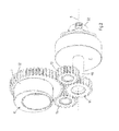
- Fig. 1 shows a part of an embodiment of a reciprocating piston mechanism 1 according to the invention, which is suitable for an internal combustion engine.
- the reciprocating piston mechanism 1 comprises a crankcase 15, which supports a crankshaft 2 by crankshaft bearings 3, see Figs. 4 and 5 .
- the crankshaft 2 includes a crankpin 4 and is rotatable with respect to the crankcase 15 about a crankshaft axis 5.
- the reciprocating piston mechanism 1 comprises a crank member 6 which is rotatably mounted on the crankpin 4.
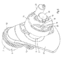
- the crank member 6 is provided with a bearing portion 7 which is disposed eccentrically with respect to the crankpin 4, see Fig. 2 .
- the bearing portion 7 has an outer circumferential wall which bears a big end 8 of a connecting rod 9.
- the connecting rod 9 is rotatably mounted on the crank member 6 via its big end 8.
- the connecting rod 9 also includes a small end 10 to which a piston 11 is rotatably connected.
- Figs. 2 and 3 show a part of the embodiment of Fig. 1 as seen from different sides.
- the crankshaft 2 and connecting rod 9 are not shown for clarity reasons.
- Figs. 4 and 5 show the same part, but including the crankshaft 2.
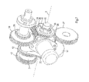
- the crank member 6 is provided with a crank member gear 12 which meshes with two intermediate gears 13.
- the crank member 6 and the crank member gear 12 may be made of one piece, but the crank member gear 12 may be pressed onto a cylindrical base part of the crank member 6, as well.
- the intermediate gears 13 are rotatably mounted to the crankshaft 2 and their axes of rotation extend parallel to the crankshaft axis 5.
- Each of the intermediate gears 13 also meshes with an auxiliary gear 14.
- the auxiliary gear 14 is fixed to an auxiliary shaft 16.
- the auxiliary shaft 16 extends concentrically through the crankshaft 2 and is rotatable with respect to the crankshaft 2 about the crankshaft axis 5.
- the auxiliary shaft 16 is rotatable about an auxiliary shaft axis which substantially coincides with the crankshaft axis 5.
- the centre line of the auxiliary gear 14 coincides with the crankshaft axis 5.
- Figs. 1 , 4 and 5 show that the auxiliary gear 14, the intermediate gears 13 and the crank member gear 12 are mounted at the same side of a crank arm 17 of the crankshaft 2. This can also be seen in the side view of Fig. 9 .
- the crank arm 17 and the adjacent crankshaft bearing 3 are integrated such that the auxiliary shaft 16 extends through both.
- the auxiliary shaft 16 extends within an outer circumference of the crankshaft bearing 3.
- the intermediate gears 13 are disposed at a side of the crankshaft 2 where a counterweight is located which creates a compact structure.
- crank member gear 12 the intermediate gears 13 and the auxiliary gears 14 may be external gears. Due to this configuration the reciprocating piston mechanism 1 can be built in a compact way and is simpler than those known in the art.
- the gear dimension can be selected such that under operating conditions the crank member 6 rotates in the same direction as the crankshaft 2 and at half speed thereof.
- the direction of rotation is defined with respect to the crankcase.
- the directions and speeds of rotation are achieved when the gear ratio between the crank member gear 12 and the auxiliary gear 14 is two and the auxiliary shaft 16 is hold at a constant angular position with respect to the crankcase 15.
- the intermediate gears 13 and the auxiliary gear 14 are located at the same side of the crank arm 17 since in practice the diameter of the auxiliary gear 14 is relatively small, which would lead to a small diameter of the crankshaft 2 at the location of the auxiliary gear 14 if this was mounted rotatably on the crankshaft 2 at the opposite side of the crank arm 17.
- a function of the intermediate gears 13 is to turn the auxiliary gear 14 in the correct direction of rotation in case of applying a gear transmission between the crank member 6 and the auxiliary shaft 16.
- the number of teeth of the intermediate gears 13 is not relevant for the transmission ratio between the crank member gear 12 and the auxiliary gear 14.
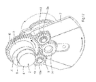
- Figs. 17-20 show four different positions of the crankshaft 2 with respect to the crankcase 15.
- the crank member 6 and the auxiliary gear 14 are provided with marks A, B, see Fig. 17 .
- the direction of rotation of the crankshaft 2 and the crank member 6 with respect to the crankcase 15 are shown by respective arrows.
- Fig. 17 shows the position of top dead centre. In the position as shown in Fig. 18 the crankshaft 2 has rotated anti clockwise by 180° with respect to the crankcase.
- the auxiliary gear 14 has maintained its angular position whereas the crank member gear 12 has also rotated anti clockwise with respect to the crankcase 15, but by an angle of 90°.
- Figs. 19 and 20 show further steps of rotation of the crankshaft 2 by steps of 180°.
- Figs. 17-20 show that two full rotations of the crankshaft 2 corresponds to one full rotation of the crank member 6, as defined with respect to the crankcase 2.
- the reciprocating piston mechanism 1 as shown in Figs. 1-5 provides the opportunity to adjust the top dead centre of the piston 11, hence its compression ratio, by changing the angular position of the auxiliary shaft 16 with respect to the crankcase 15.
- the mechanism 1 is provided with a torsion spring 18 which is fixed to the auxiliary shaft 16, on the one hand, and to the crankcase 15, on the other hand.
- a control ring 19 is attached to the auxiliary shaft 16, for example by means of pressing, and provided with recesses 20 which are located at mutual angular distances about the crankshaft axis 5.
- the mechanism 1 also comprises an actuator 21 which controls a pin (not shown) that fits in each of the recesses 20. Under stable running conditions the pin holds the control ring 19 at a fixed position with respect to the crankcase 15 and the mechanism 1 runs at a fixed compression ratio.
- auxiliary shaft 16 may vibrate in rotational direction due to the presence of the torsion spring 18, which vibration is initiate by varying combustion forces in case of an internal combustion.
- the average angular position of the auxiliary shaft 16 is then determined by a natural balance between the actual load of the auxiliary shaft 16 on the torsion spring 18 and the actual spring force of the torsion spring 18 on the auxiliary shaft 16. At a higher load due to increased combustion forces the action and reaction force between the auxiliary shaft. 16 and the torsion spring 18, i.e. the natural balance, lies at a higher level.
- the embodiment as shown in Fig. 3 works as follows. If a different compression ratio is desired the pin is retracted out of the corresponding recess 20 by the actuator 21 at a predetermined engine load. For example, if a lower compression ratio is desired the actual relatively high rotational force of the auxiliary shaft 16 on the torsion spring 18 exceeds the spring force of the torsion spring 18, causing the auxiliary shaft 16 including the control ring 19 to turn in the direction of the resultant force. If the pin is displaced back towards the control ring 19 the pin fits into another recess 20. If the control ring 19 should be turned in the opposite direction in order to obtain a higher compression ratio, i.e.
- the actual rotational force of the auxiliary shaft 16 on the spring 22 at the corresponding relatively low engine load is smaller than the spring force of the torsion spring 18, hence turning the control ring 19 to the opposite direction.
- the control ring 19 can then be fixed with respect to the crankcase 15 by means of inserting the pin into the corresponding recess 20.
- the actuator 21 may be controlled electrically, hydraulically or the like.
- the circumferential surface of the control ring 19 may be part of a bearing in order to support the control ring 19 by the crankcase 15.
- the crankcase 15 may bear the control ring 19 by means of a ball bearing 19a, see Fig. 10 , but alternative bearings are conceivable.
- the angular position of the auxiliary shaft 16 is monitored by a sensor 22, which may be a simple potentiometer.
- the sensor is mounted to the crankcase 15.
- the signal from the sensor 22 is an indication of the actual compression ratio.
- crank member gear 12 and the auxiliary gear 14 are located next to each other within the same plane.
- Most piston mechanisms have piston strokes, which may not allow the configuration as shown in Figs. 1-5 .
- the intermediate gears 13 may be lengthened such that they extend beyond the crank member gear 12 in at least one direction thereof, whereas the auxiliary gear 14 meshes with the intermediate gears 13 at the extended portions thereof such that the auxiliary gear 14 partly overlaps the crank member gear 12.
- Fig. 6 where the auxiliary gear 14 is located in front of the crank member gear 12.
- the sum of the outer diameters of the crank member gear 12 and the auxiliary gear 14 is larger than a piston stroke, whereas the gears 12-14 are located at the same side of the crank arm 17.
- crank member 6 comprises a second crank member gear 12' for driving further crank members in case of a multi-cylinder reciprocating piston mechanism.
- the crank member gear 12 and the second crank member gear 12' are located at opposite end portions of the crank member 6.
- the big end 8 of the connecting rod 9 is disposed between the crank member gear 12 and the second crank member gear 12'.
- Figs. 13-16 show an embodiment of a multi-cylinder internal combustion engines in which the second crank member gear 12' drives crank member gears that are provided at other crank pins.
- the second crank member gear 12' meshes with a further auxiliary gear 34 which is fixed to a shaft 35 that extends through an adjacent crank arm 17' and/or crank arms and/or main bearings, and on which shaft 35 another auxiliary gear 36 is fixed which drives a further crank member gear 37 of an adjacent crank pin.
- Figs. 6 and 13-16 show that the width of the crank member gear 12 is smaller than that of the second crank member gear 12'. This is possible since the crank member gear 12 meshes with two intermediate gears 13, whereas the second crank member gear 12' meshes with only one further auxiliary gear 34.
- the diameter of the crank member gear 12 that meshes with the intermediate gears 13 may be different from the diameter of the second crank member gear 12' and the further crank member gears 37. This may be desired for packaging reasons at the crank arm 17. In such a case a relative small crank member gear 12 may be pressed onto the cylindrical base part of the crank member 6. In respect of the second crank member gear 12' and the further crank member gears 37 and the other auxiliary gears 36 it is relevant that identical transmission ratios are applied.
- Figs. 7 and 8 show a drive means of the auxiliary gear 14 for adjusting the compression ratio of the mechanism 1 in a continuous manner instead of by means of discrete steps as described in relation to the embodiment that is shown in Figs. 3 and 5 .
- the alternative drive means comprises an actuator 23 in the form of an electric motor, which is able to drive the auxiliary gear 14 via a worm 24 and worm gear 25 which is fixed to the auxiliary shaft 16, but other alternative drive means are conceivable.
- the worm 24 Upon rotation of the worm 24 the top and bottom dead centre of the piston 11 can be influenced.
- the torsion spring 18 could be omitted.
- the torsion spring 18 may be appropriate in order to balance the actual force of the worm gear 25 onto the worm 24, hence requiring relatively limited power to drive the worm 24.
- the actual force of the worm gear 25 onto the worm 24 may be caused by combustion forces in case of an internal combustion engine.
- An advantage of applying a drive means including the worm 24 is that it provides the opportunity to determine the actual rotational force of the auxiliary shaft 16 on the worm 24. In case of an internal combustion engine this force is directly related to combustion pressure on the piston 11.
- the force may be measured by a force or pressure sensor at the worm 24, for example a piezo electric element or the like.
- the sensor may be incorporated in the bearings of the worm 24.
- the signal may be used for misfire detection, for example.
- auxiliary shaft 16 provides the opportunity to measure combustion forces in alternative manners, for example by means of measuring torque of the auxiliary shaft 16.
- Figs. 7 and 8 also show transfer members for driving auxiliary parts in case of an internal combustion engine. Both embodiments in Figs. 7 and 8 have a power take-off gear 26 which is attached to the crankshaft 2.
- the power take-off gear 26 meshes with a first drive gear 27, for example for driving an oil pump, and a second drive gear 28, for example for driving a camshaft.
- the embodiment of Fig. 7 shows that the second drive gear 28 is mounted on a common axis with a sprocket wheel 29 for driving a chain.
- the embodiment of Fig. 8 shows that the second drive gear 28 is mounted on a common axis with a pulley 30 for driving a belt.
- the pulley 30 or sprocket wheel 29 may be replaced by a wheel for driving a toothed belt. Since the pulley 30 and the sprocket 29 are located on a shaft that extends parallel to the crankshaft 2 the mechanism 1 can be built compact in the longitudinal direction of the crankshaft 2, despite the presence of parts of the drive means for turning the auxiliary gear 14 at the end of the crankshaft 2.
- Fig. 9 shows a side view of the embodiment as shown in Figs. 4 and 5 . It can be seen that the gears 12-14 are partly located in a recess of the crank arm 17. This provides the opportunity to minimize the length of the mechanism 1 as seen along the crankshaft 2.
- Fig. 10 shows a side view of the embodiment as shown in Fig. 7 . It can be seen that in this embodiment the gears 12-14 are not located within a common plane as explained in relation to the embodiment of Fig. 6 .
- the auxiliary gear 14 partly overlaps the crank member gear 12 as seen in a direction along their centre lines.
- the intermediate gears 13 are rotatably mounted to the crank arm 17 of the crankshaft 2.
- the intermediate gears 13 are rotatable to respective intermediate shafts 13a via plain bearings, needle bearings or the like (not shown), which intermediate shafts 13a are pressed in a bracket 31.
- the intermediate shafts 13a fit in respective holes in the crank arm 17.
- the intermediate gears 13a are mounted onto the intermediate shafts 13a, after which the bracket 31 is pressed onto the intermediate shafts 13a and fixed to the crank arm 17 through a bolt 32.
- the bracket 31 also prevents displacement of the auxiliary gear 14 in a direction away from the crank arm 17.
- Figs. 11 and 12 show an alternative embodiment of the mechanism 1 according to the invention. Parts that are similar to those in the embodiments as described hereinbefore are indicated by corresponding reference signs.
- the crank member gear 12 and the auxiliary gear 14 are replaced by respective wheels 12a and 14a for driving a toothed belt 33.
- This transmission may also be an alternative belt or a combination of sprocket wheels and a chain.
- Fig. 21 shows an alternative crank member 6 which is suitable for a reciprocating piston mechanism having a V arrangement, for example a V-engine.
- the crank member 6 comprises two crank member gears 12. Furthermore, the crank member 6 is provided with two bearing portions 7, which are angled with respect to each other about the centreline of the crank member 6. Due to this configuration the corresponding pistons reach their respective top dead centres at different angles of the crankshaft.
- the invention provides a relatively simple reciprocating piston mechanism which provides the possibility of designing a compact embodiment of the mechanism.
- the reciprocating piston mechanism may be extended to larger mechanisms having more pistons than the embodiments as described hereinbefore.
- the crank member may be cylindrical instead of eccentrical, which appears to result in lower friction losses than in a conventional mechanism having no crank member and gear transmission for driving the crank member.
Abstract
Description
- The present invention relates to a reciprocating piston mechanism.
- A reciprocating piston mechanism is described in an earlier application
PCT/EP2009/059040 - The present invention aims to provide a further improved reciprocating piston mechanism.
- For this purpose the reciprocating piston mechanism comprises the features as defined in
claim 1. - The advantage of this mechanism is that the number of gears is minimized. The applicant has discovered that an engine comprising the reciprocating piston mechanism according to the invention has lower friction losses than a conventional engine without the crank member and gear transmissions.
- In a practical embodiment the bearing portion is eccentrically disposed with respect to the crankpin. This provides the opportunity to influence the bottom and top dead centre of the piston. Particularly, in case the mechanism is applied in an internal combustion engine it is advantageous to be able to adjust the compression ratio in terms of efficiency.
- The gear ratio between the crank member gear and the auxiliary gear may be two. In this case the crank member rotates in the same direction as the crankshaft and at half speed thereof if the auxiliary gear has a fixed angular position with respect to the crankcase. When the bearing portion is eccentrically disposed with respect to the crankpin, this provides the opportunity to change the compression ratio upon adjusting the angular position of the auxiliary gear.
- The mechanism may be provided with a drive means for turning the auxiliary gear with respect to the crankcase about the crankshaft axis.
- The drive means may comprise a stop block, which is adapted to fix the auxiliary shaft at different angular positions with respect to the crankcase.
- More specifically, the stop block may comprise a control ring which is fixed to the auxiliary shaft and is provided with a plurality of recesses, and an actuator including a controlled displaceable pin that fits in each of the respective recesses. Preferably, the drive means is provided with a spring that is fixed to the auxiliary shaft and the crankcase. If the mechanism is applied in an internal combustion engine the actual combustion forces caused by the combustion stroke may force the auxiliary shaft to turn in angular direction against the spring force, when the pin is retracted from the corresponding recess. At a desired angular position of the auxiliary shaft the pin can be moved back to the control ring such that the pin fits in another recess. The control ring may be rotated in opposite direction by selecting an engine load at which the spring force is higher than the actual rotational force of the auxiliary shaft on the spring.
- It is also possible that the drive means is provided with a spring that is fixed to the auxiliary shaft and the crankcase without a locking member for fixing the angular position of the auxiliary shaft. In such a case the angular position of the auxiliary shaft is automatically balanced on the basis of the actual force of the auxiliary shaft onto the spring and the actual spring force onto the auxiliary shaft.
- Alternatively, the drive means may comprise a drivable worm meshing with a worm gear which is fixed to the auxiliary shaft. This provides the opportunity to vary the angular position of the auxiliary gear in a continuous manner. Furthermore, this embodiment of the mechanism may be provided with a pressure sensor at the worm which is an indication of the combustion pressure. It is noted that, the worm in combination with a pressure sensor is not necessarily related to a mechanism as described hereinbefore; it may also be applied in other reciprocating piston mechanisms in which, for example, the angular position of a central gear is driven by a worm to adapt the compression ratio, for example in the mechanism as described in
PCT/EP2009/059040 - The invention is also related to a reciprocating piston mechanism according to
claim 10. The mechanism provides the opportunity to vary the top dead centre of the piston by means of adjusting the angular position of the auxiliary shaft with respect to the crankcase. In practice the crank member and the auxiliary wheel are driveably coupled to each other by means of a transmission, formed by gears, chains, belts or the like. It is noted that the speed of rotation of the crank member and the crankshaft is defined in respect to the crankcase. - In a preferred embodiment the crank member gear meshes with at least a further intermediate gear which also meshes with the auxiliary gear, since this distributes forces within the mechanism.
- The invention will hereafter be elucidated with reference to the schematic drawings showing embodiments of the invention by way of example.
-
Fig. 1 is a perspective view of an embodiment of a reciprocating piston mechanism according to the invention. -
Figs. 2 and3 are perspective views of a part of the embodiment ofFig. 1 on a larger scale and seen from different sides. -
Figs. 4 and5 are similar toFigs. 2 and3 , but illustrating the part including the crankshaft. -
Fig. 6 is a perspective view of a part of an alternative embodiment of the part as shown inFigs. 2 and3 . -
Fig. 7 is a perspective view of a part of an internal combustion engine which is provided with an embodiment of the mechanism according to the invention. -
Fig. 8 is a comparable view asFig. 7 , but showing an alternative embodiment as seen from a different side. -
Fig. 9 is a side view of the embodiment as shown inFigs. 4 and5 . -
Fig. 10 is a side view of the embodiment as shown inFig. 7 . -
Fig. 11 is a similar view asFig. 1 , but showing an alternative embodiment. -
Fig. 12 is a perspective view of a part of the embodiment ofFig. 11 on a larger scale. -
Fig. 13 is a perspective view of a multi-cylinder internal combustion engine which is provided with an embodiment of a reciprocating piston mechanism according to the invention. -
Fig. 14 is a similar view asFig. 13 , but without showing the crankshaft. -
Fig. 15 is a side view of the embodiment as shown inFig. 14 . -
Fig. 16 is a perspective view of a part of the embodiment as shown inFig. 13 . -
Figs. 17-20 are similar views asFig. 4 in which a bracket is eliminated to illustrate positions of different parts under operating conditions. -
Fig. 21 is a perspective view of an alternative embodiment of a crank member, which is suitable for a reciprocating piston mechanism in V arrangement. -
Fig. 1 shows a part of an embodiment of a reciprocatingpiston mechanism 1 according to the invention, which is suitable for an internal combustion engine. Thereciprocating piston mechanism 1 comprises acrankcase 15, which supports acrankshaft 2 bycrankshaft bearings 3, seeFigs. 4 and5 . Thecrankshaft 2 includes acrankpin 4 and is rotatable with respect to thecrankcase 15 about acrankshaft axis 5. - The reciprocating
piston mechanism 1 comprises acrank member 6 which is rotatably mounted on thecrankpin 4. Thecrank member 6 is provided with abearing portion 7 which is disposed eccentrically with respect to thecrankpin 4, seeFig. 2 . The bearingportion 7 has an outer circumferential wall which bears abig end 8 of a connectingrod 9. Thus, the connectingrod 9 is rotatably mounted on thecrank member 6 via itsbig end 8. The connectingrod 9 also includes asmall end 10 to which apiston 11 is rotatably connected. -
Figs. 2 and3 show a part of the embodiment ofFig. 1 as seen from different sides. Thecrankshaft 2 and connectingrod 9 are not shown for clarity reasons.Figs. 4 and5 show the same part, but including thecrankshaft 2. - The
crank member 6 is provided with acrank member gear 12 which meshes with twointermediate gears 13. Thecrank member 6 and thecrank member gear 12 may be made of one piece, but thecrank member gear 12 may be pressed onto a cylindrical base part of thecrank member 6, as well. Theintermediate gears 13 are rotatably mounted to thecrankshaft 2 and their axes of rotation extend parallel to thecrankshaft axis 5. Each of theintermediate gears 13 also meshes with anauxiliary gear 14. Theauxiliary gear 14 is fixed to anauxiliary shaft 16. Theauxiliary shaft 16 extends concentrically through thecrankshaft 2 and is rotatable with respect to thecrankshaft 2 about thecrankshaft axis 5. Thus, theauxiliary shaft 16 is rotatable about an auxiliary shaft axis which substantially coincides with thecrankshaft axis 5. As a consequence, the centre line of theauxiliary gear 14 coincides with thecrankshaft axis 5. -
Figs. 1 ,4 and5 show that theauxiliary gear 14, theintermediate gears 13 and thecrank member gear 12 are mounted at the same side of acrank arm 17 of thecrankshaft 2. This can also be seen in the side view ofFig. 9 . Thecrank arm 17 and theadjacent crankshaft bearing 3 are integrated such that theauxiliary shaft 16 extends through both. Thus, theauxiliary shaft 16 extends within an outer circumference of thecrankshaft bearing 3. It can be seen inFig. 1 that theintermediate gears 13 are disposed at a side of thecrankshaft 2 where a counterweight is located which creates a compact structure. - In the embodiment as shown in
Figs. 1-5 thecrank member gear 12, theintermediate gears 13 and the auxiliary gears 14 may be external gears. Due to this configuration thereciprocating piston mechanism 1 can be built in a compact way and is simpler than those known in the art. - The gear dimension can be selected such that under operating conditions the
crank member 6 rotates in the same direction as thecrankshaft 2 and at half speed thereof. The direction of rotation is defined with respect to the crankcase. The directions and speeds of rotation are achieved when the gear ratio between thecrank member gear 12 and theauxiliary gear 14 is two and theauxiliary shaft 16 is hold at a constant angular position with respect to thecrankcase 15. In order to achieve the desired gear ratio it is relevant that theintermediate gears 13 and theauxiliary gear 14 are located at the same side of thecrank arm 17 since in practice the diameter of theauxiliary gear 14 is relatively small, which would lead to a small diameter of thecrankshaft 2 at the location of theauxiliary gear 14 if this was mounted rotatably on thecrankshaft 2 at the opposite side of thecrank arm 17. - It is noted that a function of the
intermediate gears 13 is to turn theauxiliary gear 14 in the correct direction of rotation in case of applying a gear transmission between thecrank member 6 and theauxiliary shaft 16. The number of teeth of theintermediate gears 13 is not relevant for the transmission ratio between thecrank member gear 12 and theauxiliary gear 14. - In order to illustrate the functioning of the mechanism under operating conditions
Figs. 17-20 show four different positions of thecrankshaft 2 with respect to thecrankcase 15. For illustrative reasons thecrank member 6 and theauxiliary gear 14 are provided with marks A, B, seeFig. 17 . The direction of rotation of thecrankshaft 2 and thecrank member 6 with respect to thecrankcase 15 are shown by respective arrows.Fig. 17 shows the position of top dead centre. In the position as shown inFig. 18 thecrankshaft 2 has rotated anti clockwise by 180° with respect to the crankcase. It can be seen that theauxiliary gear 14 has maintained its angular position whereas thecrank member gear 12 has also rotated anti clockwise with respect to thecrankcase 15, but by an angle of 90°.Figs. 19 and20 show further steps of rotation of thecrankshaft 2 by steps of 180°.Figs. 17-20 show that two full rotations of thecrankshaft 2 corresponds to one full rotation of thecrank member 6, as defined with respect to thecrankcase 2. - The
reciprocating piston mechanism 1 as shown inFigs. 1-5 provides the opportunity to adjust the top dead centre of thepiston 11, hence its compression ratio, by changing the angular position of theauxiliary shaft 16 with respect to thecrankcase 15. InFigs. 1-5 and more specifically inFig. 3 it can be seen that themechanism 1 is provided with atorsion spring 18 which is fixed to theauxiliary shaft 16, on the one hand, and to thecrankcase 15, on the other hand. Acontrol ring 19 is attached to theauxiliary shaft 16, for example by means of pressing, and provided withrecesses 20 which are located at mutual angular distances about thecrankshaft axis 5. Themechanism 1 also comprises anactuator 21 which controls a pin (not shown) that fits in each of therecesses 20. Under stable running conditions the pin holds thecontrol ring 19 at a fixed position with respect to thecrankcase 15 and themechanism 1 runs at a fixed compression ratio. - It is conceivable to eliminate the
actuator 21 including the pin, which means that theauxiliary shaft 16 is not lockable to thecrankcase 15. In that case, under operating conditions theauxiliary shaft 16 may vibrate in rotational direction due to the presence of thetorsion spring 18, which vibration is initiate by varying combustion forces in case of an internal combustion. The average angular position of theauxiliary shaft 16 is then determined by a natural balance between the actual load of theauxiliary shaft 16 on thetorsion spring 18 and the actual spring force of thetorsion spring 18 on theauxiliary shaft 16. At a higher load due to increased combustion forces the action and reaction force between the auxiliary shaft. 16 and thetorsion spring 18, i.e. the natural balance, lies at a higher level. This means that thetorsion spring 18 will be compressed and theauxiliary shaft 16 is turned by a certain angle with respect to thecrankcase 15. At a lower load the opposite effect is achieved. As a consequence, an automatic adjustment of the angular position of theauxiliary shaft 16 is attained. - In case of applying the
mechanism 1 in an internal combustion engine the embodiment as shown inFig. 3 works as follows. If a different compression ratio is desired the pin is retracted out of thecorresponding recess 20 by theactuator 21 at a predetermined engine load. For example, if a lower compression ratio is desired the actual relatively high rotational force of theauxiliary shaft 16 on thetorsion spring 18 exceeds the spring force of thetorsion spring 18, causing theauxiliary shaft 16 including thecontrol ring 19 to turn in the direction of the resultant force. If the pin is displaced back towards thecontrol ring 19 the pin fits into anotherrecess 20. If thecontrol ring 19 should be turned in the opposite direction in order to obtain a higher compression ratio, i.e. switching to a lower engine load, the actual rotational force of theauxiliary shaft 16 on thespring 22 at the corresponding relatively low engine load is smaller than the spring force of thetorsion spring 18, hence turning thecontrol ring 19 to the opposite direction. Thecontrol ring 19 can then be fixed with respect to thecrankcase 15 by means of inserting the pin into the correspondingrecess 20. - It is noted that the
actuator 21 may be controlled electrically, hydraulically or the like. Furthermore, the circumferential surface of thecontrol ring 19 may be part of a bearing in order to support thecontrol ring 19 by thecrankcase 15. Thecrankcase 15 may bear thecontrol ring 19 by means of aball bearing 19a, seeFig. 10 , but alternative bearings are conceivable. - The angular position of the
auxiliary shaft 16 is monitored by asensor 22, which may be a simple potentiometer. The sensor is mounted to thecrankcase 15. The signal from thesensor 22 is an indication of the actual compression ratio. - In the embodiment as shown in
Figs. 1-5 thecrank member gear 12 and theauxiliary gear 14 are located next to each other within the same plane. Most piston mechanisms have piston strokes, which may not allow the configuration as shown inFigs. 1-5 . In such a case theintermediate gears 13 may be lengthened such that they extend beyond thecrank member gear 12 in at least one direction thereof, whereas theauxiliary gear 14 meshes with theintermediate gears 13 at the extended portions thereof such that theauxiliary gear 14 partly overlaps thecrank member gear 12. This is shown inFig. 6 where theauxiliary gear 14 is located in front of thecrank member gear 12. In this embodiment the sum of the outer diameters of thecrank member gear 12 and theauxiliary gear 14 is larger than a piston stroke, whereas the gears 12-14 are located at the same side of thecrank arm 17. - Furthermore,
Fig. 6 shows that thecrank member 6 comprises a second crank member gear 12' for driving further crank members in case of a multi-cylinder reciprocating piston mechanism. Thecrank member gear 12 and the second crank member gear 12' are located at opposite end portions of thecrank member 6. Thebig end 8 of the connectingrod 9 is disposed between thecrank member gear 12 and the second crank member gear 12'.Figs. 13-16 show an embodiment of a multi-cylinder internal combustion engines in which the second crank member gear 12' drives crank member gears that are provided at other crank pins. The second crank member gear 12' meshes with a furtherauxiliary gear 34 which is fixed to ashaft 35 that extends through an adjacent crank arm 17' and/or crank arms and/or main bearings, and on whichshaft 35 anotherauxiliary gear 36 is fixed which drives a further crankmember gear 37 of an adjacent crank pin.Figs. 6 and13-16 show that the width of thecrank member gear 12 is smaller than that of the second crank member gear 12'. This is possible since thecrank member gear 12 meshes with twointermediate gears 13, whereas the second crank member gear 12' meshes with only one furtherauxiliary gear 34. - The diameter of the
crank member gear 12 that meshes with theintermediate gears 13 may be different from the diameter of the second crank member gear 12' and the further crank member gears 37. This may be desired for packaging reasons at thecrank arm 17. In such a case a relative small crankmember gear 12 may be pressed onto the cylindrical base part of thecrank member 6. In respect of the second crank member gear 12' and the further crank member gears 37 and the otherauxiliary gears 36 it is relevant that identical transmission ratios are applied. -
Figs. 7 and8 show a drive means of theauxiliary gear 14 for adjusting the compression ratio of themechanism 1 in a continuous manner instead of by means of discrete steps as described in relation to the embodiment that is shown inFigs. 3 and5 . The alternative drive means comprises anactuator 23 in the form of an electric motor, which is able to drive theauxiliary gear 14 via aworm 24 andworm gear 25 which is fixed to theauxiliary shaft 16, but other alternative drive means are conceivable. Upon rotation of theworm 24 the top and bottom dead centre of thepiston 11 can be influenced. In the embodiment as shown inFigs. 7 and8 thetorsion spring 18 could be omitted. However, thetorsion spring 18 may be appropriate in order to balance the actual force of theworm gear 25 onto theworm 24, hence requiring relatively limited power to drive theworm 24. The actual force of theworm gear 25 onto theworm 24 may be caused by combustion forces in case of an internal combustion engine. - An advantage of applying a drive means including the
worm 24 is that it provides the opportunity to determine the actual rotational force of theauxiliary shaft 16 on theworm 24. In case of an internal combustion engine this force is directly related to combustion pressure on thepiston 11. The force may be measured by a force or pressure sensor at theworm 24, for example a piezo electric element or the like. The sensor may be incorporated in the bearings of theworm 24. The signal may be used for misfire detection, for example. - It is noted that the
auxiliary shaft 16 provides the opportunity to measure combustion forces in alternative manners, for example by means of measuring torque of theauxiliary shaft 16. -
Figs. 7 and8 also show transfer members for driving auxiliary parts in case of an internal combustion engine. Both embodiments inFigs. 7 and8 have a power take-off gear 26 which is attached to thecrankshaft 2. The power take-off gear 26 meshes with afirst drive gear 27, for example for driving an oil pump, and asecond drive gear 28, for example for driving a camshaft. The embodiment ofFig. 7 shows that thesecond drive gear 28 is mounted on a common axis with asprocket wheel 29 for driving a chain. The embodiment ofFig. 8 shows that thesecond drive gear 28 is mounted on a common axis with apulley 30 for driving a belt. In an alternative embodiment thepulley 30 orsprocket wheel 29 may be replaced by a wheel for driving a toothed belt. Since thepulley 30 and thesprocket 29 are located on a shaft that extends parallel to thecrankshaft 2 themechanism 1 can be built compact in the longitudinal direction of thecrankshaft 2, despite the presence of parts of the drive means for turning theauxiliary gear 14 at the end of thecrankshaft 2. -
Fig. 9 shows a side view of the embodiment as shown inFigs. 4 and5 . It can be seen that the gears 12-14 are partly located in a recess of thecrank arm 17. This provides the opportunity to minimize the length of themechanism 1 as seen along thecrankshaft 2. -
Fig. 10 shows a side view of the embodiment as shown inFig. 7 . It can be seen that in this embodiment the gears 12-14 are not located within a common plane as explained in relation to the embodiment ofFig. 6 . Theauxiliary gear 14 partly overlaps thecrank member gear 12 as seen in a direction along their centre lines. - Referring to the embodiment as shown in
Fig. 4 it can be seen that theintermediate gears 13 are rotatably mounted to thecrank arm 17 of thecrankshaft 2. In this case theintermediate gears 13 are rotatable to respectiveintermediate shafts 13a via plain bearings, needle bearings or the like (not shown), whichintermediate shafts 13a are pressed in abracket 31. Theintermediate shafts 13a fit in respective holes in thecrank arm 17. Upon assembly of themechanism 1 theintermediate shafts 13a are pressed into thecrankshaft 2, then theintermediate gears 13 are mounted onto theintermediate shafts 13a, after which thebracket 31 is pressed onto theintermediate shafts 13a and fixed to thecrank arm 17 through abolt 32. Thebracket 31 also prevents displacement of theauxiliary gear 14 in a direction away from thecrank arm 17. -
Figs. 11 and12 show an alternative embodiment of themechanism 1 according to the invention. Parts that are similar to those in the embodiments as described hereinbefore are indicated by corresponding reference signs. In this case thecrank member gear 12 and theauxiliary gear 14 are replaced byrespective wheels toothed belt 33. This transmission may also be an alternative belt or a combination of sprocket wheels and a chain. -
Fig. 21 shows an alternative crankmember 6 which is suitable for a reciprocating piston mechanism having a V arrangement, for example a V-engine. Thecrank member 6 comprises two crank member gears 12. Furthermore, thecrank member 6 is provided with two bearingportions 7, which are angled with respect to each other about the centreline of thecrank member 6. Due to this configuration the corresponding pistons reach their respective top dead centres at different angles of the crankshaft. - It is noted that different features of the embodiments as described hereinbefore may be combined.
- From the foregoing, it will be clear that the invention provides a relatively simple reciprocating piston mechanism which provides the possibility of designing a compact embodiment of the mechanism.
- The invention is not limited to the embodiments shown in the drawings and described hereinbefore, which may be varied in different manners within the scope of the claims and their technical equivalents. For example, the reciprocating piston mechanism may be extended to larger mechanisms having more pistons than the embodiments as described hereinbefore. In an alternative embodiment the crank member may be cylindrical instead of eccentrical, which appears to result in lower friction losses than in a conventional mechanism having no crank member and gear transmission for driving the crank member.
Claims (14)
- A reciprocating piston mechanism (1) comprising a crankcase (15);
a crankshaft (2) having at least a crankpin (4), said crankshaft (2) being supported by the crankcase (15) and rotatable with respect thereto about a crankshaft axis (5);
at least a connecting rod (9) including a big end (8) and a small end (10);
a piston (11) being rotatably connected to the small end (10);
a crank member (6) being rotatably mounted on the crankpin (4), and comprising at least a bearing portion (7) having an outer circumferential wall which bears the big end (8) of the connecting rod (9) such that the connecting rod (9) is rotatably mounted on the bearing portion (7) of the crank member (6) via the big end (8);
wherein the crank member (6) is provided with a crank member gear (12), being an external gear, which meshes with at least an intermediate gear (13), being an external gear, which intermediate gear (13) also meshes with an auxiliary gear (14) being an external gear, wherein the auxiliary gear (14) is fixed to an auxiliary shaft (16) which extends concentrically through the crankshaft (2), wherein the crankshaft (2) and the auxiliary shaft (16) are rotatable with respect to each other. - A reciprocating piston mechanism (1) according to claim 1, wherein the gear ratio between the crank member gear (12) and the auxiliary gear (14) is two.
- A reciprocating piston mechanism (1) according to claim 1 or 2, wherein the bearing portion (7) is eccentrically disposed with respect to the crankpin (4).
- A reciprocating piston mechanism (1) according to one of the preceding claims, wherein the crank member gear (12) meshes with at least a further intermediate gear (13) which also meshes with the auxiliary gear (14).
- A reciprocating piston mechanism (1) according to one of the preceding claims, wherein the mechanism (1) is provided with a drive means (18-21, 23-25) for turning the auxiliary gear (14) with respect to the crankcase (15) about the crankshaft axis (5).
- A reciprocating piston mechanism (1) according to claim 5, wherein the drive means comprises a stop block, which is adapted to fix the auxiliary shaft (16) at different angular positions with respect to the crankcase (15).
- A reciprocating piston mechanism (1) according to claim 6, wherein the stop block comprises a control ring (19) which is fixed to the auxiliary shaft (16) and provided with a plurality of recesses (20), and an actuator (21) including a controlled displaceable pin that fits in each of the respective recesses (20), wherein the mechanism (1) is preferably provided with a spring (18) that is fixed to the auxiliary shaft (16) and the crankcase (15).
- A reciprocating piston mechanism (1) according to claim 5, wherein the drive means comprises a drivable worm (24) meshing with a worm gear (25) which is fixed to the auxiliary shaft (16).
- A reciprocating piston mechanism (1) according to one of the preceding claims, wherein the intermediate gear (13) extends beyond the crank member gear (12) in at least one longitudinal direction thereof, wherein the auxiliary gear (14) meshes with the intermediate gear (13) such that the auxiliary gear (14) partly overlaps the crank member gear (12).
- A reciprocating piston mechanism (1) comprising a crankcase (15);
a crankshaft (2) having at least a crankpin (4), said crankshaft (2) being supported by the crankcase (15) and rotatable with respect thereto about a crankshaft axis (3);
at least a connecting rod (9) including a big end (8) and a small end (10);
a piston (11) being rotatably connected to the small end (10);
a crank member (6) being rotatably mounted on the crankpin (4), and comprising at least a bearing portion (7) having an outer circumferential wall which bears the big end (8) of the connecting rod (9) such that the connecting rod (9) is rotatably mounted on the bearing portion (7) of the crank member (6) via the big end (8);
wherein the crank member (6) is driveably coupled to an auxiliary wheel (14, 14a) which is fixed to an auxiliary shaft (16) that extends concentrically through the crankshaft (2), wherein the crankshaft (2) and the auxiliary shaft (16) are rotatable with respect to each other, wherein the auxiliary wheel (14, 14a) is disposed at the same side of an adjacent crank arm (17) as the crank member (6), wherein the mechanism (1) is adapted such that under operating conditions the crank member (6) rotates in the same direction as the crankshaft (2) and at half speed thereof, whereas the auxiliary shaft (16) has a substantially fixed angular position with respect to the crankcase (15). - A reciprocating piston mechanism (1) according to claim 10, wherein the crank member (6) comprises a crank member wheel (12a) which is driveably coupled to the auxiliary wheel (14a) by means of a toothed belt (33).
- A reciprocating piston mechanism (1) according to claim 10, wherein the crank member (6) comprises a crank member sprocket and the auxiliary wheel is formed by an auxiliary sprocket, wherein the crank member sprocket is drivabl by means of a chain.
- A reciprocating piston mechanism (1) according to claim 10, wherein the crank member (6) is provided with a crank member gear (12), and the auxiliary wheel is formed by an auxiliary gear (14) being an external gear, wherein the crank member gear (12) and the auxiliary gear (14) are driveably coupled to each other by at least an intermediate gear (13), being an external gear (14), which meshes with the auxiliary gear (14) and the crank meniber gear (12).
- A reciprocating piston mechanism (1) according to claim 5, wherein the drive means (18-21, 23-25) is provided with a spring (18) that is fixed to the auxiliary shaft (16) and the crankcase (15).
Priority Applications (10)
| Application Number | Priority Date | Filing Date | Title |
|---|---|---|---|
| EP12152309.6A EP2620614B1 (en) | 2012-01-24 | 2012-01-24 | A reciprocating piston mechanism |
| US14/373,470 US10234006B2 (en) | 2012-01-24 | 2013-01-24 | Reciprocating piston mechanism |
| EP13701256.3A EP2828501A1 (en) | 2012-01-24 | 2013-01-24 | A reciprocating piston mechanism |
| BR112014017873-9A BR112014017873B1 (en) | 2012-01-24 | 2013-01-24 | ALTERNATIVE PISTON MECHANISM |
| RU2014129394A RU2623136C2 (en) | 2012-01-24 | 2013-01-24 | Piston unit with reciprocating motion |
| JP2014552664A JP6305347B2 (en) | 2012-01-24 | 2013-01-24 | Reciprocating piston mechanism |
| CN201380009329.8A CN104204455B (en) | 2012-01-24 | 2013-01-24 | A kind of reciprocating-piston mechanism |
| PCT/EP2013/051333 WO2013110700A1 (en) | 2012-01-24 | 2013-01-24 | A reciprocating piston mechanism |
| KR1020147023200A KR102074649B1 (en) | 2012-01-24 | 2013-01-24 | A reciprocating piston mechanism |
| CA2861277A CA2861277C (en) | 2012-01-24 | 2013-01-24 | A reciprocating piston mechanism |
Applications Claiming Priority (1)
| Application Number | Priority Date | Filing Date | Title |
|---|---|---|---|
| EP12152309.6A EP2620614B1 (en) | 2012-01-24 | 2012-01-24 | A reciprocating piston mechanism |
Publications (2)
| Publication Number | Publication Date |
|---|---|
| EP2620614A1 true EP2620614A1 (en) | 2013-07-31 |
| EP2620614B1 EP2620614B1 (en) | 2016-11-09 |
Family
ID=47603746
Family Applications (2)
| Application Number | Title | Priority Date | Filing Date |
|---|---|---|---|
| EP12152309.6A Active EP2620614B1 (en) | 2012-01-24 | 2012-01-24 | A reciprocating piston mechanism |
| EP13701256.3A Withdrawn EP2828501A1 (en) | 2012-01-24 | 2013-01-24 | A reciprocating piston mechanism |
Family Applications After (1)
| Application Number | Title | Priority Date | Filing Date |
|---|---|---|---|
| EP13701256.3A Withdrawn EP2828501A1 (en) | 2012-01-24 | 2013-01-24 | A reciprocating piston mechanism |
Country Status (9)
| Country | Link |
|---|---|
| US (1) | US10234006B2 (en) |
| EP (2) | EP2620614B1 (en) |
| JP (1) | JP6305347B2 (en) |
| KR (1) | KR102074649B1 (en) |
| CN (1) | CN104204455B (en) |
| BR (1) | BR112014017873B1 (en) |
| CA (1) | CA2861277C (en) |
| RU (1) | RU2623136C2 (en) |
| WO (1) | WO2013110700A1 (en) |
Cited By (17)
| Publication number | Priority date | Publication date | Assignee | Title |
|---|---|---|---|---|
| US20140360292A1 (en) | 2012-01-24 | 2014-12-11 | Joannes Jacobus Josephus SLEPER | Reciprocating piston mechanism |
| EP2873835A1 (en) * | 2013-11-13 | 2015-05-20 | Gomecsys B.V. | A method of assembling and an assembly of a crankshaft and a crank member |
| EP2902603A1 (en) * | 2014-01-31 | 2015-08-05 | Gomecsys B.V. | An internal combustion engine including variable compression ratio |
| CN104832279A (en) * | 2015-01-08 | 2015-08-12 | 武汉富国发动机科技有限公司 | Novel energy-saving internal combustion engine |
| EP2930329A1 (en) * | 2014-04-08 | 2015-10-14 | Gomecsys B.V. | An internal combustion engine including variable compression ratio |
| FR3022299A1 (en) * | 2014-06-12 | 2015-12-18 | Peugeot Citroen Automobiles Sa | INTERNAL COMBUSTION ENGINE WITH VARIABLE COMPRESSION RATIO |
| WO2016026486A1 (en) * | 2014-08-20 | 2016-02-25 | Schaeffler Technologies AG & Co. KG | Device for changing a compression ratio of a cylinder unit of a reciprocating piston combustion engine |
| CN105673795A (en) * | 2016-03-23 | 2016-06-15 | 刘有双 | Accelerator |
| WO2016174320A1 (en) * | 2015-04-28 | 2016-11-03 | Peugeot Citroen Automobiles Sa | Combustion engine for a motor vehicle, comprising a system for varying the compression ratio |
| WO2016174322A1 (en) * | 2015-04-28 | 2016-11-03 | Peugeot Citroen Automobiles Sa | Eccentric component for a system for varying the compression ratio of a combustion engine |
| EP3103986A1 (en) | 2015-06-08 | 2016-12-14 | Gomecsys B.V. | A four-stroke internal combustion engine including variable compression ratio and a vehicle |
| FR3050234A1 (en) * | 2016-04-19 | 2017-10-20 | Peugeot Citroen Automobiles Sa | ASSEMBLY FOR THERMAL ENGINE COMPRESSION RATE VARIATION SYSTEM |
| EP3540270A1 (en) | 2018-03-12 | 2019-09-18 | Gomecsys B.V. | A gear train and an internal combustion engine |
| US10557409B2 (en) | 2015-10-22 | 2020-02-11 | Gomecsys B.V. | Heat engine comprising a system for varying the compression ratio |
| EP3608523A1 (en) * | 2018-08-09 | 2020-02-12 | Gomecsys B.V. | An eccentric member and a v-type internal combustion engine |
| US10626791B2 (en) | 2015-11-17 | 2020-04-21 | MCE 5 Development | Variable compression ratio engine |
| DE102018128524A1 (en) * | 2018-11-14 | 2020-05-14 | Bayerische Motoren Werke Aktiengesellschaft | Compression ratio changing device, reciprocating piston internal combustion engine and working device |
Families Citing this family (27)
| Publication number | Priority date | Publication date | Assignee | Title |
|---|---|---|---|---|
| BR112012000948A2 (en) * | 2009-07-15 | 2016-03-15 | Joannes Jacobus Josephus Sleper | reciprocating piston mechanism |
| EP2905449B1 (en) | 2014-02-11 | 2018-05-09 | Gomecsys B.V. | An internal combustion engine including variable compression ratio and a method of operating the engine |
| EP2907986B1 (en) * | 2014-02-18 | 2017-05-03 | Gomecsys B.V. | A four-stroke internal combustion engine with variable compression ratio |
| FR3036146B1 (en) * | 2015-05-11 | 2017-05-26 | Peugeot Citroen Automobiles Sa | ECCENTRIC PIECE FOR A COMPRESSION RATE SYSTEM OF A THERMAL ENGINE |
| KR102004105B1 (en) * | 2015-07-21 | 2019-07-25 | 닛산 지도우샤 가부시키가이샤 | Internal combustion engine |
| CN105156620B (en) * | 2015-07-24 | 2018-04-17 | 李云峰 | A kind of crankmotion switching mechanism |
| DE102015112690B4 (en) * | 2015-08-03 | 2023-04-20 | Ovalo Gmbh | Actuator system, in particular for coupling to the adjustment shaft of an internal combustion engine for setting the expansion stroke and/or the compression ratio |
| FR3042815B1 (en) * | 2015-10-22 | 2019-08-02 | Psa Automobiles Sa. | THERMAL MOTOR PROVIDED WITH A SYSTEM OF VARIATION OF THE COMPRESSION RATE |
| CN105605081A (en) * | 2016-03-18 | 2016-05-25 | 蔡建龙 | Engine crankshaft |
| FR3052495B1 (en) * | 2016-06-09 | 2020-01-10 | Peugeot Citroen Automobiles Sa | HEAT ENGINE WITH IMPROVED COMPRESSION RATE VARIATION SYSTEM |
| US10119463B2 (en) * | 2016-12-09 | 2018-11-06 | Mark Albert Sokalski | Infinitely variable compression ratio and single stroke length mechanism or dual stroke length mechanism of reciprocating 2-cycle or 4-cycle internal combustion engine |
| JP2018105159A (en) * | 2016-12-22 | 2018-07-05 | いすゞ自動車株式会社 | engine |
| DE102017200918B4 (en) | 2017-01-20 | 2022-10-06 | Bayerische Motoren Werke Aktiengesellschaft | Crank mechanism for a reciprocating internal combustion engine |
| JP7101459B2 (en) * | 2017-04-26 | 2022-07-15 | Ntn株式会社 | Electric actuator |
| US10801591B2 (en) * | 2017-06-23 | 2020-10-13 | Crown Packaging Technology, Inc. | System and method for converting rotating motion into linear motion |
| DE102018201988B3 (en) | 2018-02-08 | 2019-05-29 | Audi Ag | Connecting rod for an internal combustion engine and corresponding internal combustion engine |
| EP3719339A1 (en) | 2019-04-05 | 2020-10-07 | Gomecsys B.V. | An apparatus including an adjusting system for adjusting a rotational position of a shaft with respect to a shaft holding member |
| EP3726023A1 (en) | 2019-04-17 | 2020-10-21 | Gomecsys B.V. | An internal combustion engine |
| RU2716521C1 (en) * | 2019-07-30 | 2020-03-12 | Общество с ограниченной ответственностью "Завод дозировочной техники "Ареопаг" | Piston device of pump |
| EP3808955A1 (en) | 2019-10-15 | 2021-04-21 | Gomecsys B.V. | An internal combustion engine with variable compression ratio |
| CN111022603B (en) * | 2020-01-07 | 2021-07-20 | 重庆大学 | Staggered planetary roller screw speed reducer |
| US11131240B1 (en) * | 2020-05-15 | 2021-09-28 | GM Global Technology Operations LLC | Engine assembly including a force splitter for varying compression ratio using an actuator |
| GEP20227367B (en) * | 2020-08-06 | 2022-03-25 | Ramzan Goytemirov | Engine having compression ratio control mechanism |
| CN112504054A (en) * | 2020-11-24 | 2021-03-16 | 重庆钧顶机械制造有限公司 | Timing gear meshing runout degree gauge for crank link mechanism |
| DE102021103790A1 (en) | 2021-02-18 | 2022-08-18 | Bayerische Motoren Werke Aktiengesellschaft | Adjusting device for setting a variable compression ratio of a reciprocating engine, motor vehicle and method |
| US11255374B1 (en) * | 2021-03-04 | 2022-02-22 | VenTec LLC | Engine crank |
| EP4086443A1 (en) | 2021-05-05 | 2022-11-09 | Gomecsys B.V. | An internal combustion engine and a method of operating the internal combustion engine |
Citations (5)
| Publication number | Priority date | Publication date | Assignee | Title |
|---|---|---|---|---|
| DE164819C (en) * | 1904-08-02 | 1905-11-16 | ||
| DE329861C (en) * | 1918-04-12 | 1920-12-04 | Motorenfabrik Oberursel A G | Elevation control for rotary engines of aircraft |
| FR986605A (en) * | 1943-11-23 | 1951-08-02 | Device for varying, in operation, the compression ratio of an engine | |
| EP0184042A2 (en) * | 1984-11-23 | 1986-06-11 | Politechnika Warszawska | Crank mechanism of the internal combustion piston engine with variable crankthrow |
| WO2009018863A1 (en) * | 2007-08-09 | 2009-02-12 | Gomecsys B.V. | A reciprocating piston mechanism |
Family Cites Families (74)
| Publication number | Priority date | Publication date | Assignee | Title |
|---|---|---|---|---|
| FR636243A (en) * | 1928-04-04 | |||
| DD242077A (en) | ||||
| DE181913C (en) | ||||
| US460642A (en) * | 1891-10-06 | Variable crank-motion | ||
| US1207429A (en) * | 1916-01-04 | 1916-12-05 | James Currie Morison | Means for equalizing piston displacement. |
| GB150291A (en) * | 1917-12-13 | 1921-11-18 | Clerget Blin & Cie | Improvements in or relating to explosion engines with variable compression |
| GB173252A (en) | 1920-07-19 | 1921-12-19 | Charles Kane Salisbury | Improvements in internal combustion engines |
| US1553009A (en) | 1923-07-23 | 1925-09-08 | Stuke Ernest | Engine |
| DE488059C (en) | 1925-05-16 | 1929-12-18 | Louis Damblanc | Internal combustion engine with variable piston stroke |
| US1767352A (en) | 1927-03-26 | 1930-06-24 | Damblanc Louis | Crank shaft |
| US1964096A (en) * | 1931-11-21 | 1934-06-26 | Emmitt M Tucker | Connecting rod mounting |
| FR861611A (en) | 1939-07-29 | 1941-02-13 | Internal combustion engine with variable displacement and automatic compression ratio | |
| US2271766A (en) | 1940-05-06 | 1942-02-03 | Harry A Huebotter | Engine |
| US2369747A (en) * | 1942-07-30 | 1945-02-20 | Elvin R Munn | Engine |
| FR1014314A (en) | 1946-04-10 | 1952-08-13 | Variable displacement internal combustion engine | |
| GB1094649A (en) | 1963-12-16 | 1967-12-13 | Henry Eddington Roberts | Improvements in or relating to machines having a reciprocating member coupled to a rotatable member |
| US3686972A (en) * | 1970-05-28 | 1972-08-29 | Edward M Mcwhorter | Internal combustion engine variable throw crankshaft |
| JPS5247093B2 (en) * | 1972-05-10 | 1977-11-30 | ||
| US3861239A (en) * | 1972-06-05 | 1975-01-21 | Edward M Mcwhorter | Internal combustion engine combustion control crankshaft |
| US3886805A (en) * | 1974-04-09 | 1975-06-03 | Ivan Koderman | Crank gear for the conversion of a translational motion into rotation |
| US4152955A (en) * | 1975-01-02 | 1979-05-08 | Mcwhorter Edward M | Engine compound crankshaft |
| US4073196A (en) * | 1976-08-13 | 1978-02-14 | Gilbert T. Hendren, Jr. | Cranking system of varying radius |
| DE2720284C3 (en) | 1977-05-05 | 1981-05-27 | Huf, Franz, Prof. Dipl.-Ing., 7750 Konstanz | Slider crank system series |
| US4179942A (en) * | 1978-01-09 | 1979-12-25 | Matthews Leslie C | Variable ratio crank assembly |
| DE2947882A1 (en) | 1979-11-28 | 1981-07-23 | Volkswagenwerk Ag, 3180 Wolfsburg | Piston engine crank drive without connecting rod - includes stationary surface formed by wheel concentric to lengthwise axis |
| AU7857681A (en) | 1980-12-16 | 1982-06-24 | Charles Radcliff Furlonger | Internal combustion engine |
| JPH0627969B2 (en) | 1984-06-29 | 1994-04-13 | キヤノン株式会社 | Character processor |
| JPS61187931A (en) | 1985-02-18 | 1986-08-21 | Asahi Chem Ind Co Ltd | Adsorbent of arsenic in aqueous solution |
| EP0222841A1 (en) | 1985-05-24 | 1987-05-27 | COOPER, Robert Alan | Crankshaft crank |
| JPH0443620Y2 (en) * | 1985-12-28 | 1992-10-15 | ||
| DE3634536A1 (en) | 1986-10-10 | 1987-02-19 | Toan Dat Tran | Crankshaft drive with doubled piston strokes |
| DE3642681A1 (en) | 1986-12-13 | 1988-06-23 | Michael Schenk | Crankshaft, particularly for reciprocating-piston combustion engines |
| US4860702A (en) | 1988-03-21 | 1989-08-29 | Doundoulakis George J | Compression ratio control in reciprocating piston engines |
| EP0345366A1 (en) | 1988-06-08 | 1989-12-13 | Alfredo Buffoli | Eight cycle or diesel type internal combustion engine |
| JPH0361135A (en) | 1989-07-31 | 1991-03-15 | Masateru Maruyama | Transmission method of signal indicator connected with switch in operating section of vehicle such as car and ship and will signal to same signal indicator |
| JPH0422717A (en) * | 1990-05-17 | 1992-01-27 | Mitsubishi Motors Corp | Compression ratio varying device of internal combustion engine |
| GB2258271A (en) * | 1991-08-01 | 1993-02-03 | Ford Motor Co | Variable compression ratio i.c.engine. |
| FR2680402A1 (en) | 1991-08-12 | 1993-02-19 | Bes Jean Paul | Mechanism for reversible conversion of a uniform rotational movement into a sinusoidal (simple harmonic) reciprocating rectilinear motion of variable stroke, and engine including such a mechanism |
| US5133314A (en) * | 1991-12-23 | 1992-07-28 | Langstroth Steven W | Linkage arms for minimizing piston wobble |
| US5265566A (en) | 1991-12-23 | 1993-11-30 | General Motors Corporation | Assembled seal disc for a crankshaft |
| US5170757A (en) | 1991-12-24 | 1992-12-15 | Damien Gamache | Variable horsepower output gearing for piston engine |
| SE513061C2 (en) | 1992-06-30 | 2000-06-26 | Fanja Ltd | Method and apparatus for changing the compression ratio in an internal combustion engine |
| SE501331C2 (en) | 1993-05-28 | 1995-01-16 | Saab Automobile | Structural inclusion of internal combustion engine in order to reduce engine noise |
| US5482015A (en) | 1994-07-11 | 1996-01-09 | Fish; Robert D. | Device for coupling reciprocating and rotating motions |
| RU2053391C1 (en) * | 1994-03-18 | 1996-01-27 | Евгений Иванович Воронкин | Internal combustion engine with extended working stroke |
| WO1996027079A1 (en) | 1995-02-28 | 1996-09-06 | Tk Design Ag | Reciprocating piston type internal combustion engine with variable compression ratio |
| GB9611135D0 (en) | 1996-05-29 | 1996-07-31 | Gang Nail Systems Limited | Connector |
| JP2829287B2 (en) | 1996-10-23 | 1998-11-25 | ロングウェルジャパン株式会社 | Crank device |
| AUPO885297A0 (en) * | 1997-09-01 | 1997-09-25 | Bresland, Claude Neil | Compression engine |
| US5927236A (en) * | 1997-10-28 | 1999-07-27 | Gonzalez; Luis Marino | Variable stroke mechanism for internal combustion engine |
| NL1009211C2 (en) | 1998-05-19 | 1999-11-22 | L H De Gooijer Holding B V | Crank-connecting rod mechanism. |
| US6453869B1 (en) * | 2001-01-04 | 2002-09-24 | Mooremac, Llc | Internal combustion engine with variable ratio crankshaft assembly |
| DE60200787T2 (en) | 2001-01-24 | 2005-09-08 | Hasan Basri Özdamar | INTERNAL COMBUSTION ENGINE WITH ROTATABLE PLEUELBOLZ |
| ITRM20010038A1 (en) | 2001-01-26 | 2002-07-26 | Foggia Andrea Di | DEVICE FOR THE TRANSFORMATION OF THE ALTERNATE STRAIGHT MOTORCYCLE INTO A ROTARY AND VICEVERSA MOTORCYCLE, EQUIPPED WITH ONE OR MORE S-MOUNTED SATELLITES |
| JP2002286020A (en) | 2001-03-26 | 2002-10-03 | Shinko Denki:Kk | Crank mechanism of reciprocating engine |
| US20030183026A1 (en) | 2002-03-29 | 2003-10-02 | Korniyenko Alexsandr Y. | Apparatus for converting rotary to reciprocating motion and vice versa |
| AU2003229184A1 (en) | 2002-05-17 | 2003-12-02 | Normand Beaudoin | Retro-mechanical, post-mechanical, bi-mechanical traction engines |
| DE10230425A1 (en) | 2002-07-06 | 2004-01-22 | Bayerische Motoren Werke Ag | Bearing bush for IC engine crankshaft is made up of two halves which fit together with butt joints and have end flanges, halves being held together by clips across butt joints |
| DE10230426A1 (en) | 2002-07-06 | 2004-01-22 | Bayerische Motoren Werke Ag | Bearing bush for IC engine crankshaft comprises two halves which fit together with butt joints and have end flanges, halves being held together by collars in shape of part of circle which fit across butt joints |
| WO2005059330A2 (en) * | 2003-12-11 | 2005-06-30 | Dow Glendal R | Variable crankshaft |
| RU2280771C2 (en) * | 2004-05-19 | 2006-07-27 | Владимир Александрович Ворогушин | Motion converting device |
| US7185557B2 (en) | 2004-06-29 | 2007-03-06 | Thomas Mark Venettozzi | Epitrochoidal crankshaft mechanism and method |
| JP2007113471A (en) | 2005-10-19 | 2007-05-10 | Toyota Motor Corp | Internal combustion engine |
| EP1959112A1 (en) | 2007-02-16 | 2008-08-20 | Gomecsys B.V. | A reciprocating piston mechanism, a method of assembling this, and an internal combustion engine |
| EP1983215A1 (en) | 2007-04-20 | 2008-10-22 | Gomecsys B.V. | Reciprocating piston machine and internal combustion engine |
| JP2009036030A (en) | 2007-07-31 | 2009-02-19 | Fuji Heavy Ind Ltd | Crankshaft structure of high expansion ratio engine |
| US20090133653A1 (en) | 2007-11-26 | 2009-05-28 | Thomas Duzzie | Spur gear drive for an internal combustion engine |
| US8001948B2 (en) | 2008-01-30 | 2011-08-23 | Chuy-Nan Chio | Kinetic energy generation apparatus having increased power output |
| WO2009100759A1 (en) | 2008-02-13 | 2009-08-20 | Gomecsys B.V. | A reciprocating piston mechanism and a method of increasing internal egr in an internal combustion engine |
| BR112012000948A2 (en) | 2009-07-15 | 2016-03-15 | Joannes Jacobus Josephus Sleper | reciprocating piston mechanism |
| DE102011085647A1 (en) | 2011-11-03 | 2013-05-08 | Bayerische Motoren Werke Aktiengesellschaft | Divided bearing shell i.e. eccentric cam shell, for use in crank drive of piston-internal combustion engine, has mounting unit comprising tension rod with tension head, where cross-section of tension head is larger than that of tension rod |
| EP2620614B1 (en) | 2012-01-24 | 2016-11-09 | Gomecsys B.V. | A reciprocating piston mechanism |
| WO2013160501A1 (en) | 2012-04-23 | 2013-10-31 | Garcia Sanchez Eduardo | Kinematic chain for positioning eccentric bearings which rotate on the crankpins of the crankshaft of an engine with a variable compression ratio |
| WO2014005258A1 (en) | 2012-07-02 | 2014-01-09 | Qualcomm Incorporated | Methods and apparatuses for enabling fast early termination of voice frames on the uplink |
-
2012
- 2012-01-24 EP EP12152309.6A patent/EP2620614B1/en active Active
-
2013
- 2013-01-24 CA CA2861277A patent/CA2861277C/en active Active
- 2013-01-24 BR BR112014017873-9A patent/BR112014017873B1/en active IP Right Grant
- 2013-01-24 WO PCT/EP2013/051333 patent/WO2013110700A1/en active Application Filing
- 2013-01-24 JP JP2014552664A patent/JP6305347B2/en active Active
- 2013-01-24 US US14/373,470 patent/US10234006B2/en active Active
- 2013-01-24 RU RU2014129394A patent/RU2623136C2/en active
- 2013-01-24 CN CN201380009329.8A patent/CN104204455B/en active Active
- 2013-01-24 EP EP13701256.3A patent/EP2828501A1/en not_active Withdrawn
- 2013-01-24 KR KR1020147023200A patent/KR102074649B1/en active IP Right Grant
Patent Citations (5)
| Publication number | Priority date | Publication date | Assignee | Title |
|---|---|---|---|---|
| DE164819C (en) * | 1904-08-02 | 1905-11-16 | ||
| DE329861C (en) * | 1918-04-12 | 1920-12-04 | Motorenfabrik Oberursel A G | Elevation control for rotary engines of aircraft |
| FR986605A (en) * | 1943-11-23 | 1951-08-02 | Device for varying, in operation, the compression ratio of an engine | |
| EP0184042A2 (en) * | 1984-11-23 | 1986-06-11 | Politechnika Warszawska | Crank mechanism of the internal combustion piston engine with variable crankthrow |
| WO2009018863A1 (en) * | 2007-08-09 | 2009-02-12 | Gomecsys B.V. | A reciprocating piston mechanism |
Cited By (35)
| Publication number | Priority date | Publication date | Assignee | Title |
|---|---|---|---|---|
| US10234006B2 (en) | 2012-01-24 | 2019-03-19 | Gomecsys B.V. | Reciprocating piston mechanism |
| US20140360292A1 (en) | 2012-01-24 | 2014-12-11 | Joannes Jacobus Josephus SLEPER | Reciprocating piston mechanism |
| CN105849388A (en) * | 2013-11-13 | 2016-08-10 | 戈梅克赛斯股份有限公司 | A method of assembling and an assembly of a crankshaft and a crank member |
| EP2873835A1 (en) * | 2013-11-13 | 2015-05-20 | Gomecsys B.V. | A method of assembling and an assembly of a crankshaft and a crank member |
| EP2873834A1 (en) * | 2013-11-13 | 2015-05-20 | Gomecsys B.V. | A method of assembling and an assembly of a crankshaft and a crank member |
| WO2015071297A1 (en) * | 2013-11-13 | 2015-05-21 | Gomecsys B.V. | A method of assembling and an assembly of a crankshaft and a crank member |
| US10233966B2 (en) | 2013-11-13 | 2019-03-19 | Gomecsys B.V. | Method of assembling and an assembly of a crankshaft and a crank member |
| CN105849388B (en) * | 2013-11-13 | 2018-11-23 | 戈梅克赛斯股份有限公司 | The component and assemble method of crankshaft and crank member |
| EP2902603A1 (en) * | 2014-01-31 | 2015-08-05 | Gomecsys B.V. | An internal combustion engine including variable compression ratio |
| WO2015114001A1 (en) * | 2014-01-31 | 2015-08-06 | Gomecsys B.V. | An internal combustion engine including variable compression ratio |
| US10145299B2 (en) | 2014-04-08 | 2018-12-04 | Gomecsys B.V. | Internal combustion engine including variable compression ratio |
| EP2930329A1 (en) * | 2014-04-08 | 2015-10-14 | Gomecsys B.V. | An internal combustion engine including variable compression ratio |
| WO2015155233A1 (en) * | 2014-04-08 | 2015-10-15 | Gomecsys B.V. | An internal combustion engine including variable compression ratio |
| FR3022299A1 (en) * | 2014-06-12 | 2015-12-18 | Peugeot Citroen Automobiles Sa | INTERNAL COMBUSTION ENGINE WITH VARIABLE COMPRESSION RATIO |
| US10087834B2 (en) | 2014-08-20 | 2018-10-02 | Schaeffler Technologies AG & Co. KG | Device for changing a compression ratio of a cylinder unit of a reciprocating piston combustion engine |
| WO2016026486A1 (en) * | 2014-08-20 | 2016-02-25 | Schaeffler Technologies AG & Co. KG | Device for changing a compression ratio of a cylinder unit of a reciprocating piston combustion engine |
| CN104832279A (en) * | 2015-01-08 | 2015-08-12 | 武汉富国发动机科技有限公司 | Novel energy-saving internal combustion engine |
| CN104832279B (en) * | 2015-01-08 | 2018-01-02 | 武汉富国发动机科技有限公司 | New energy-saving IC engine |
| WO2016174320A1 (en) * | 2015-04-28 | 2016-11-03 | Peugeot Citroen Automobiles Sa | Combustion engine for a motor vehicle, comprising a system for varying the compression ratio |
| WO2016174322A1 (en) * | 2015-04-28 | 2016-11-03 | Peugeot Citroen Automobiles Sa | Eccentric component for a system for varying the compression ratio of a combustion engine |
| FR3035682A1 (en) * | 2015-04-28 | 2016-11-04 | Peugeot Citroen Automobiles Sa | INTERNAL COMBUSTION ENGINE OF A MOTOR VEHICLE WITH A SYSTEM OF VARIATION IN THE RATE OF COMPRESSION |
| FR3035681A1 (en) * | 2015-04-28 | 2016-11-04 | Peugeot Citroen Automobiles Sa | ECCENTRIC PIECE FOR A COMPRESSION RATE SYSTEM OF A THERMAL ENGINE |
| EP3103986A1 (en) | 2015-06-08 | 2016-12-14 | Gomecsys B.V. | A four-stroke internal combustion engine including variable compression ratio and a vehicle |
| WO2016198349A1 (en) | 2015-06-08 | 2016-12-15 | Gomecsys B.V. | A four-stroke internal combustion engine including variable compression ratio and a vehicle |
| US10605178B2 (en) | 2015-06-08 | 2020-03-31 | Gomecsys B.V. | Four-stroke internal combustion engine including variable compression ratio and a vehicle |
| US10557409B2 (en) | 2015-10-22 | 2020-02-11 | Gomecsys B.V. | Heat engine comprising a system for varying the compression ratio |
| US10626791B2 (en) | 2015-11-17 | 2020-04-21 | MCE 5 Development | Variable compression ratio engine |
| CN105673795A (en) * | 2016-03-23 | 2016-06-15 | 刘有双 | Accelerator |
| WO2017182731A1 (en) * | 2016-04-19 | 2017-10-26 | Psa Automobiles S.A. | Assembly for heat engine compression rate variation system |
| FR3050234A1 (en) * | 2016-04-19 | 2017-10-20 | Peugeot Citroen Automobiles Sa | ASSEMBLY FOR THERMAL ENGINE COMPRESSION RATE VARIATION SYSTEM |
| EP3540270A1 (en) | 2018-03-12 | 2019-09-18 | Gomecsys B.V. | A gear train and an internal combustion engine |
| EP3608523A1 (en) * | 2018-08-09 | 2020-02-12 | Gomecsys B.V. | An eccentric member and a v-type internal combustion engine |
| DE102018128524A1 (en) * | 2018-11-14 | 2020-05-14 | Bayerische Motoren Werke Aktiengesellschaft | Compression ratio changing device, reciprocating piston internal combustion engine and working device |
| US11401859B2 (en) | 2018-11-14 | 2022-08-02 | Bayerische Motoren Werke Aktiengesellschaft | Device for varying a compression ratio, reciprocating-piston internal combustion engine and working device |
| DE102018128524B4 (en) | 2018-11-14 | 2022-09-22 | Bayerische Motoren Werke Aktiengesellschaft | Compression ratio changing device, reciprocating internal combustion engine and working device |
Also Published As
| Publication number | Publication date |
|---|---|
| RU2623136C2 (en) | 2017-06-22 |
| JP2015508470A (en) | 2015-03-19 |
| KR102074649B1 (en) | 2020-03-02 |
| BR112014017873B1 (en) | 2022-10-18 |
| US20140360292A1 (en) | 2014-12-11 |
| EP2828501A1 (en) | 2015-01-28 |
| RU2014129394A (en) | 2016-03-20 |
| CN104204455B (en) | 2018-03-27 |
| CA2861277A1 (en) | 2013-08-01 |
| US10234006B2 (en) | 2019-03-19 |
| EP2620614B1 (en) | 2016-11-09 |
| CN104204455A (en) | 2014-12-10 |
| BR112014017873A8 (en) | 2017-07-11 |
| CA2861277C (en) | 2020-06-16 |
| JP6305347B2 (en) | 2018-04-04 |
| BR112014017873A2 (en) | 2017-06-20 |
| WO2013110700A1 (en) | 2013-08-01 |
| KR20140113737A (en) | 2014-09-24 |
Similar Documents
| Publication | Publication Date | Title |
|---|---|---|
| EP2620614B1 (en) | A reciprocating piston mechanism | |
| EP2454458B1 (en) | A reciprocating piston mechanism | |
| EP2257700B1 (en) | A reciprocating piston mechanism and a method of increasing internal egr in an internal combustion engine | |
| US6588384B2 (en) | Apparatus for varying the compression ratio of an internal-combustion engine | |
| CA2560324C (en) | Vibration compensating pulley | |
| EP1983215A1 (en) | Reciprocating piston machine and internal combustion engine | |
| EP2902603A1 (en) | An internal combustion engine including variable compression ratio | |
| EP2025893A1 (en) | A reciprocating piston mechanism | |
| EP2905448A1 (en) | An internal combustion engine including variable compression ratio and a method of operating the engine | |
| EP2905449B1 (en) | An internal combustion engine including variable compression ratio and a method of operating the engine | |
| JP2002540356A (en) | A connecting element for connecting two axially parallel shafts which are coaxially arranged at the front and rear and are laterally spaced from each other | |
| US8550945B2 (en) | Vibration compensating pulley | |
| JPH0419454A (en) | Crank drive with planetary pivot pin | |
| WO2011110325A2 (en) | Mechanism for converting a reciprocating movement into a rotational movement and vice versa, and device comprising such a mechanism. | |
| RU2011061C1 (en) | Balancing mechanism for piston machine | |
| WO2019154689A1 (en) | A reciprocating piston mechanism | |
| JP2015169203A (en) | Parallel double shafts cranks-crank holder swing type compression ratio variable device | |
| WO2023094039A1 (en) | An eccentric member and an internal combustion engine | |
| JP2022114408A (en) | Forked connecting rod type compression ratio continuous variable device | |
| EP3540270A1 (en) | A gear train and an internal combustion engine | |
| JP2016109109A (en) | Stroke volume continuous variable device | |
| JP2011074810A (en) | Internal combustion engine | |
| TH99385A (en) | Variable stroke engine | |
| TH53273B (en) | Variable stroke engine | |
| TH42331B (en) | Power generator sets including internal combustion engines with variable compression ratio system |
Legal Events
| Date | Code | Title | Description |
|---|---|---|---|
| PUAI | Public reference made under article 153(3) epc to a published international application that has entered the european phase |
Free format text: ORIGINAL CODE: 0009012 |
|
| AK | Designated contracting states |
Kind code of ref document: A1 Designated state(s): AL AT BE BG CH CY CZ DE DK EE ES FI FR GB GR HR HU IE IS IT LI LT LU LV MC MK MT NL NO PL PT RO RS SE SI SK SM TR |
|
| AX | Request for extension of the european patent |
Extension state: BA ME |
|
| RAP1 | Party data changed (applicant data changed or rights of an application transferred) |
Owner name: GOMECSYS B.V. |
|
| 17P | Request for examination filed |
Effective date: 20140129 |
|
| RBV | Designated contracting states (corrected) |
Designated state(s): AL AT BE BG CH CY CZ DE DK EE ES FI FR GB GR HR HU IE IS IT LI LT LU LV MC MK MT NL NO PL PT RO RS SE SI SK SM TR |
|
| 17Q | First examination report despatched |
Effective date: 20150304 |
|
| GRAP | Despatch of communication of intention to grant a patent |
Free format text: ORIGINAL CODE: EPIDOSNIGR1 |
|
| INTG | Intention to grant announced |
Effective date: 20160530 |
|
| GRAS | Grant fee paid |
Free format text: ORIGINAL CODE: EPIDOSNIGR3 |
|
| GRAA | (expected) grant |
Free format text: ORIGINAL CODE: 0009210 |
|
| AK | Designated contracting states |
Kind code of ref document: B1 Designated state(s): AL AT BE BG CH CY CZ DE DK EE ES FI FR GB GR HR HU IE IS IT LI LT LU LV MC MK MT NL NO PL PT RO RS SE SI SK SM TR |
|
| REG | Reference to a national code |
Ref country code: GB Ref legal event code: FG4D |
|
| REG | Reference to a national code |
Ref country code: AT Ref legal event code: REF Ref document number: 844145 Country of ref document: AT Kind code of ref document: T Effective date: 20161115 Ref country code: CH Ref legal event code: EP |
|
| REG | Reference to a national code |
Ref country code: IE Ref legal event code: FG4D |
|
| REG | Reference to a national code |
Ref country code: DE Ref legal event code: R096 Ref document number: 602012025068 Country of ref document: DE |
|
| REG | Reference to a national code |
Ref country code: NL Ref legal event code: FP |
|
| REG | Reference to a national code |
Ref country code: FR Ref legal event code: PLFP Year of fee payment: 6 |
|
| REG | Reference to a national code |
Ref country code: SE Ref legal event code: TRGR |
|
| PG25 | Lapsed in a contracting state [announced via postgrant information from national office to epo] |
Ref country code: LV Free format text: LAPSE BECAUSE OF FAILURE TO SUBMIT A TRANSLATION OF THE DESCRIPTION OR TO PAY THE FEE WITHIN THE PRESCRIBED TIME-LIMIT Effective date: 20161109 |
|
| REG | Reference to a national code |
Ref country code: LT Ref legal event code: MG4D |
|
| REG | Reference to a national code |
Ref country code: AT Ref legal event code: MK05 Ref document number: 844145 Country of ref document: AT Kind code of ref document: T Effective date: 20161109 |
|
| PG25 | Lapsed in a contracting state [announced via postgrant information from national office to epo] |
Ref country code: LT Free format text: LAPSE BECAUSE OF FAILURE TO SUBMIT A TRANSLATION OF THE DESCRIPTION OR TO PAY THE FEE WITHIN THE PRESCRIBED TIME-LIMIT Effective date: 20161109 Ref country code: GR Free format text: LAPSE BECAUSE OF FAILURE TO SUBMIT A TRANSLATION OF THE DESCRIPTION OR TO PAY THE FEE WITHIN THE PRESCRIBED TIME-LIMIT Effective date: 20170210 Ref country code: NO Free format text: LAPSE BECAUSE OF FAILURE TO SUBMIT A TRANSLATION OF THE DESCRIPTION OR TO PAY THE FEE WITHIN THE PRESCRIBED TIME-LIMIT Effective date: 20170209 |
|
| PG25 | Lapsed in a contracting state [announced via postgrant information from national office to epo] |
Ref country code: PL Free format text: LAPSE BECAUSE OF FAILURE TO SUBMIT A TRANSLATION OF THE DESCRIPTION OR TO PAY THE FEE WITHIN THE PRESCRIBED TIME-LIMIT Effective date: 20161109 Ref country code: BE Free format text: LAPSE BECAUSE OF NON-PAYMENT OF DUE FEES Effective date: 20170131 Ref country code: IS Free format text: LAPSE BECAUSE OF FAILURE TO SUBMIT A TRANSLATION OF THE DESCRIPTION OR TO PAY THE FEE WITHIN THE PRESCRIBED TIME-LIMIT Effective date: 20170309 Ref country code: AT Free format text: LAPSE BECAUSE OF FAILURE TO SUBMIT A TRANSLATION OF THE DESCRIPTION OR TO PAY THE FEE WITHIN THE PRESCRIBED TIME-LIMIT Effective date: 20161109 Ref country code: PT Free format text: LAPSE BECAUSE OF FAILURE TO SUBMIT A TRANSLATION OF THE DESCRIPTION OR TO PAY THE FEE WITHIN THE PRESCRIBED TIME-LIMIT Effective date: 20170309 Ref country code: FI Free format text: LAPSE BECAUSE OF FAILURE TO SUBMIT A TRANSLATION OF THE DESCRIPTION OR TO PAY THE FEE WITHIN THE PRESCRIBED TIME-LIMIT Effective date: 20161109 Ref country code: ES Free format text: LAPSE BECAUSE OF FAILURE TO SUBMIT A TRANSLATION OF THE DESCRIPTION OR TO PAY THE FEE WITHIN THE PRESCRIBED TIME-LIMIT Effective date: 20161109 Ref country code: HR Free format text: LAPSE BECAUSE OF FAILURE TO SUBMIT A TRANSLATION OF THE DESCRIPTION OR TO PAY THE FEE WITHIN THE PRESCRIBED TIME-LIMIT Effective date: 20161109 Ref country code: RS Free format text: LAPSE BECAUSE OF FAILURE TO SUBMIT A TRANSLATION OF THE DESCRIPTION OR TO PAY THE FEE WITHIN THE PRESCRIBED TIME-LIMIT Effective date: 20161109 |
|
| PG25 | Lapsed in a contracting state [announced via postgrant information from national office to epo] |
Ref country code: CZ Free format text: LAPSE BECAUSE OF FAILURE TO SUBMIT A TRANSLATION OF THE DESCRIPTION OR TO PAY THE FEE WITHIN THE PRESCRIBED TIME-LIMIT Effective date: 20161109 Ref country code: EE Free format text: LAPSE BECAUSE OF FAILURE TO SUBMIT A TRANSLATION OF THE DESCRIPTION OR TO PAY THE FEE WITHIN THE PRESCRIBED TIME-LIMIT Effective date: 20161109 Ref country code: DK Free format text: LAPSE BECAUSE OF FAILURE TO SUBMIT A TRANSLATION OF THE DESCRIPTION OR TO PAY THE FEE WITHIN THE PRESCRIBED TIME-LIMIT Effective date: 20161109 Ref country code: SK Free format text: LAPSE BECAUSE OF FAILURE TO SUBMIT A TRANSLATION OF THE DESCRIPTION OR TO PAY THE FEE WITHIN THE PRESCRIBED TIME-LIMIT Effective date: 20161109 Ref country code: RO Free format text: LAPSE BECAUSE OF FAILURE TO SUBMIT A TRANSLATION OF THE DESCRIPTION OR TO PAY THE FEE WITHIN THE PRESCRIBED TIME-LIMIT Effective date: 20161109 |
|
| REG | Reference to a national code |
Ref country code: DE Ref legal event code: R097 Ref document number: 602012025068 Country of ref document: DE |
|
| PG25 | Lapsed in a contracting state [announced via postgrant information from national office to epo] |
Ref country code: SM Free format text: LAPSE BECAUSE OF FAILURE TO SUBMIT A TRANSLATION OF THE DESCRIPTION OR TO PAY THE FEE WITHIN THE PRESCRIBED TIME-LIMIT Effective date: 20161109 Ref country code: BG Free format text: LAPSE BECAUSE OF FAILURE TO SUBMIT A TRANSLATION OF THE DESCRIPTION OR TO PAY THE FEE WITHIN THE PRESCRIBED TIME-LIMIT Effective date: 20170209 Ref country code: BE Free format text: LAPSE BECAUSE OF FAILURE TO SUBMIT A TRANSLATION OF THE DESCRIPTION OR TO PAY THE FEE WITHIN THE PRESCRIBED TIME-LIMIT Effective date: 20161109 |
|
| REG | Reference to a national code |
Ref country code: CH Ref legal event code: PL |
|
| PLBE | No opposition filed within time limit |
Free format text: ORIGINAL CODE: 0009261 |
|
| STAA | Information on the status of an ep patent application or granted ep patent |
Free format text: STATUS: NO OPPOSITION FILED WITHIN TIME LIMIT |
|
| PG25 | Lapsed in a contracting state [announced via postgrant information from national office to epo] |
Ref country code: MC Free format text: LAPSE BECAUSE OF FAILURE TO SUBMIT A TRANSLATION OF THE DESCRIPTION OR TO PAY THE FEE WITHIN THE PRESCRIBED TIME-LIMIT Effective date: 20161109 |
|
| 26N | No opposition filed |
Effective date: 20170810 |
|
| PG25 | Lapsed in a contracting state [announced via postgrant information from national office to epo] |
Ref country code: LI Free format text: LAPSE BECAUSE OF NON-PAYMENT OF DUE FEES Effective date: 20170131 Ref country code: CH Free format text: LAPSE BECAUSE OF NON-PAYMENT OF DUE FEES Effective date: 20170131 |
|
| REG | Reference to a national code |
Ref country code: IE Ref legal event code: MM4A |
|
| PG25 | Lapsed in a contracting state [announced via postgrant information from national office to epo] |
Ref country code: SI Free format text: LAPSE BECAUSE OF FAILURE TO SUBMIT A TRANSLATION OF THE DESCRIPTION OR TO PAY THE FEE WITHIN THE PRESCRIBED TIME-LIMIT Effective date: 20161109 Ref country code: LU Free format text: LAPSE BECAUSE OF NON-PAYMENT OF DUE FEES Effective date: 20170124 |
|
| REG | Reference to a national code |
Ref country code: FR Ref legal event code: PLFP Year of fee payment: 7 |
|
| PG25 | Lapsed in a contracting state [announced via postgrant information from national office to epo] |
Ref country code: IE Free format text: LAPSE BECAUSE OF NON-PAYMENT OF DUE FEES Effective date: 20170124 |
|
| PG25 | Lapsed in a contracting state [announced via postgrant information from national office to epo] |
Ref country code: MT Free format text: LAPSE BECAUSE OF NON-PAYMENT OF DUE FEES Effective date: 20170124 |
|
| PG25 | Lapsed in a contracting state [announced via postgrant information from national office to epo] |
Ref country code: HU Free format text: LAPSE BECAUSE OF FAILURE TO SUBMIT A TRANSLATION OF THE DESCRIPTION OR TO PAY THE FEE WITHIN THE PRESCRIBED TIME-LIMIT; INVALID AB INITIO Effective date: 20120124 |
|
| PG25 | Lapsed in a contracting state [announced via postgrant information from national office to epo] |
Ref country code: CY Free format text: LAPSE BECAUSE OF NON-PAYMENT OF DUE FEES Effective date: 20161109 |
|
| PG25 | Lapsed in a contracting state [announced via postgrant information from national office to epo] |
Ref country code: MK Free format text: LAPSE BECAUSE OF FAILURE TO SUBMIT A TRANSLATION OF THE DESCRIPTION OR TO PAY THE FEE WITHIN THE PRESCRIBED TIME-LIMIT Effective date: 20161109 |
|
| PG25 | Lapsed in a contracting state [announced via postgrant information from national office to epo] |
Ref country code: TR Free format text: LAPSE BECAUSE OF FAILURE TO SUBMIT A TRANSLATION OF THE DESCRIPTION OR TO PAY THE FEE WITHIN THE PRESCRIBED TIME-LIMIT Effective date: 20161109 |
|
| PG25 | Lapsed in a contracting state [announced via postgrant information from national office to epo] |
Ref country code: AL Free format text: LAPSE BECAUSE OF FAILURE TO SUBMIT A TRANSLATION OF THE DESCRIPTION OR TO PAY THE FEE WITHIN THE PRESCRIBED TIME-LIMIT Effective date: 20161109 |
|
| PGFP | Annual fee paid to national office [announced via postgrant information from national office to epo] |
Ref country code: FR Payment date: 20230125 Year of fee payment: 12 |
|
| PGFP | Annual fee paid to national office [announced via postgrant information from national office to epo] |
Ref country code: SE Payment date: 20230127 Year of fee payment: 12 Ref country code: IT Payment date: 20230118 Year of fee payment: 12 Ref country code: GB Payment date: 20230127 Year of fee payment: 12 Ref country code: DE Payment date: 20230127 Year of fee payment: 12 |
|
| PGFP | Annual fee paid to national office [announced via postgrant information from national office to epo] |
Ref country code: NL Payment date: 20230130 Year of fee payment: 12 |
|
| PGFP | Annual fee paid to national office [announced via postgrant information from national office to epo] |
Ref country code: NL Payment date: 20240126 Year of fee payment: 13 |