BR112014017873B1 - ALTERNATIVE PISTON MECHANISM - Google Patents
ALTERNATIVE PISTON MECHANISM Download PDFInfo
- Publication number
- BR112014017873B1 BR112014017873B1 BR112014017873-9A BR112014017873A BR112014017873B1 BR 112014017873 B1 BR112014017873 B1 BR 112014017873B1 BR 112014017873 A BR112014017873 A BR 112014017873A BR 112014017873 B1 BR112014017873 B1 BR 112014017873B1
- Authority
- BR
- Brazil
- Prior art keywords
- gear
- auxiliary
- crank
- crank element
- crankshaft
- Prior art date
Links
Images


Classifications
-
- F—MECHANICAL ENGINEERING; LIGHTING; HEATING; WEAPONS; BLASTING
- F16—ENGINEERING ELEMENTS AND UNITS; GENERAL MEASURES FOR PRODUCING AND MAINTAINING EFFECTIVE FUNCTIONING OF MACHINES OR INSTALLATIONS; THERMAL INSULATION IN GENERAL
- F16H—GEARING
- F16H37/00—Combinations of mechanical gearings, not provided for in groups F16H1/00 - F16H35/00
- F16H37/12—Gearings comprising primarily toothed or friction gearing, links or levers, and cams, or members of at least two of these types
- F16H37/124—Gearings comprising primarily toothed or friction gearing, links or levers, and cams, or members of at least two of these types for interconverting rotary motion and reciprocating motion
-
- F—MECHANICAL ENGINEERING; LIGHTING; HEATING; WEAPONS; BLASTING
- F02—COMBUSTION ENGINES; HOT-GAS OR COMBUSTION-PRODUCT ENGINE PLANTS
- F02B—INTERNAL-COMBUSTION PISTON ENGINES; COMBUSTION ENGINES IN GENERAL
- F02B75/00—Other engines
- F02B75/04—Engines with variable distances between pistons at top dead-centre positions and cylinder heads
- F02B75/048—Engines with variable distances between pistons at top dead-centre positions and cylinder heads by means of a variable crank stroke length
-
- F—MECHANICAL ENGINEERING; LIGHTING; HEATING; WEAPONS; BLASTING
- F16—ENGINEERING ELEMENTS AND UNITS; GENERAL MEASURES FOR PRODUCING AND MAINTAINING EFFECTIVE FUNCTIONING OF MACHINES OR INSTALLATIONS; THERMAL INSULATION IN GENERAL
- F16H—GEARING
- F16H21/00—Gearings comprising primarily only links or levers, with or without slides
- F16H21/10—Gearings comprising primarily only links or levers, with or without slides all movement being in, or parallel to, a single plane
- F16H21/16—Gearings comprising primarily only links or levers, with or without slides all movement being in, or parallel to, a single plane for interconverting rotary motion and reciprocating motion
- F16H21/18—Crank gearings; Eccentric gearings
- F16H21/22—Crank gearings; Eccentric gearings with one connecting-rod and one guided slide to each crank or eccentric
-
- F—MECHANICAL ENGINEERING; LIGHTING; HEATING; WEAPONS; BLASTING
- F02—COMBUSTION ENGINES; HOT-GAS OR COMBUSTION-PRODUCT ENGINE PLANTS
- F02B—INTERNAL-COMBUSTION PISTON ENGINES; COMBUSTION ENGINES IN GENERAL
- F02B41/00—Engines characterised by special means for improving conversion of heat or pressure energy into mechanical power
- F02B41/02—Engines with prolonged expansion
- F02B41/04—Engines with prolonged expansion in main cylinders
-
- Y—GENERAL TAGGING OF NEW TECHNOLOGICAL DEVELOPMENTS; GENERAL TAGGING OF CROSS-SECTIONAL TECHNOLOGIES SPANNING OVER SEVERAL SECTIONS OF THE IPC; TECHNICAL SUBJECTS COVERED BY FORMER USPC CROSS-REFERENCE ART COLLECTIONS [XRACs] AND DIGESTS
- Y10—TECHNICAL SUBJECTS COVERED BY FORMER USPC
- Y10T—TECHNICAL SUBJECTS COVERED BY FORMER US CLASSIFICATION
- Y10T74/00—Machine element or mechanism
- Y10T74/18—Mechanical movements
- Y10T74/18056—Rotary to or from reciprocating or oscillating
- Y10T74/18208—Crank, pitman, and slide
Abstract
MECANISMO DE PISTÃO ALTERNATIVO. A presente invenção refere-se a um mecanismo de pistão alternativo (1) compreendendo: cárter (15); eixo de manivela (2), possuindo pelo menos um pino de manivela (4),suportado pelo cárter (15), girável em torno do eixo geométrico do eixo mecânico de manivela (5);pelo menos uma haste de conexão (9) incluindo: extremidade grande (8); extremidade pequena (10); pistão (11), conectado rotacionalmente à extremidade pequena (10); elemento de manivela (6) montado rotacionalmente no pino de manivela (4), compreendendo: porção de mancal (7) com parede externa circular apoiando a extremidade grande (8) da haste de conexão (9) de modo que ela seja montada rotacionalmente via a extremidade grande (8); e dotado de uma engrenagem de elemento de manivela (12). A engrenagem de elemento de manivela (12) é uma engrenagem externa, que engrena com pelo menos uma engrenagem intermediária (13). A engrenagem intermediária (13) é externa e também se engata com engrenagem auxiliar (14) fixada a eixo auxiliar (16) estendendo-se concentricamente através do eixo de manivela (2). O eixo de manivela (2) e o eixo auxiliar (16) podem girar um em relação ao outro.ALTERNATIVE PISTON MECHANISM. The present invention relates to an alternative piston mechanism (1) comprising: crankcase (15); crankshaft (2), having at least one crankpin (4), supported by the crankcase (15), rotatable around the geometric axis of the mechanical crankshaft (5); at least one connecting rod (9) including : big end (8); small end (10); piston (11), rotationally connected to the small end (10); crank element (6) rotationally mounted on the crank pin (4), comprising: bearing portion (7) with circular outer wall supporting the large end (8) of the connecting rod (9) so that it is rotationally mounted via the big end (8); and provided with a crank element gear (12). The crank element gear (12) is an external gear, which meshes with at least one intermediate gear (13). The intermediate gear (13) is external and also engages with an auxiliary gear (14) fixed to the auxiliary shaft (16) extending concentrically through the crankshaft (2). The crankshaft (2) and the auxiliary shaft (16) can rotate relative to each other.
Description
[001] A presente invenção refere-se a um mecanismo de pistão alternativo.[001] The present invention relates to an alternative piston mechanism.
[002] Um mecanismo de pistão alternativo é descrito em um pedido anterior PCT/EP 2009/059040 do requerente.[002] An alternative piston mechanism is described in an applicant's previous application PCT/EP 2009/059040.
[003] A presente invenção objetiva proporcionar um mecanismo de pistão alternativo aperfeiçoado.[003] The present invention aims to provide an improved reciprocating piston mechanism.
[004] Com essa finalidade, o mecanismo de pistão alternativo compreende as características conforme definido na reivindicação 1.[004] For this purpose, the alternative piston mechanism comprises the characteristics as defined in claim 1.
[005] A vantagem desse mecanismo é que o número de engrenagens é minimizado. O requerente descobriu que um motor compreendendo o mecanismo de pistão alternativo de acordo com a invenção tem menos perdas por atrito do que um motor convencional, sem o eixo de manivela e as transmissões de engrenagens.[005] The advantage of this mechanism is that the number of gears is minimized. Applicant has found that an engine comprising the reciprocating piston mechanism according to the invention has less frictional losses than a conventional engine without the crankshaft and gear transmissions.
[006] Em uma modalidade prática, a porção de mancal é disposta excentricamente com relação ao pino de manivela. Isso proporciona a oportunidade de influenciar o centro morto inferior e superior do pistão. Particularmente, em caso de o mecanismo ser aplicado em um motor de combustão interna, é vantajoso ser capaz de ajustar a relação de compressão em termos de eficiência.[006] In a practical embodiment, the bearing portion is arranged eccentrically with respect to the crank pin. This provides the opportunity to influence the bottom and top dead center of the piston. Particularly, in case the mechanism is applied in an internal combustion engine, it is advantageous to be able to adjust the compression ratio in terms of efficiency.
[007] As relações de engrenagens entre a engrenagem do elemento de manivela e a engrenagem auxiliar podem ser duas. Neste caso, o eixo de manivela gira na mesma direção que o eixo de manivela e na metade de sua velocidade, se a engrenagem auxiliar tiver uma posição angular fixa com relação ao cárter. Quando a porção de mancal é disposta excentricamente com relação ao pino de manivela, isso proporciona a oportunidade para mudar a relação de compressão mediante ajuste da posição angular da engrenagem auxiliar.[007] The gear ratios between the crank element gear and the auxiliary gear can be two. In this case, the crankshaft rotates in the same direction as the crankshaft and at half its speed, if the auxiliary gear has a fixed angular position with respect to the crankcase. When the bearing portion is disposed eccentrically with respect to the crank pin, this provides the opportunity to change the compression ratio by adjusting the angular position of the auxiliary gear.
[008] O mecanismo pode ser dotado de um meio de acionamento para girar a engrenagem auxiliar com relação cárter em torno do eixo geométrico de eixo de manivela.[008] The mechanism may be provided with a drive means to rotate the auxiliary gear with respect to the crankcase around the geometric axis of the crankshaft.
[009] O meio de acionamento pode compreender um bloco de batente, que é adaptado para fixar a engrenagem auxiliar em diferentes posições angulares com relação ao cárter.[009] The drive means may comprise a stop block, which is adapted to fix the auxiliary gear in different angular positions with respect to the crankcase.
[0010] Mais especificamente, o bloco de batente pode compreender um anel de controle, que é fixado à engrenagem auxiliar e é dotado de uma pluralidade de reentrâncias e um atuador, incluindo um pino deslocável, controlado, que se encaixa em cada uma das respectivas reentrâncias. De preferência, o meio de acionamento é dotado de uma mola que é fixada ao eixo auxiliar e ao cárter. Se o mecanismo for aplicado em um motor de combustão interna, as forças de combustão reais, causadas pelo curso de combustão, podem forçar o eixo mecânico auxiliar a girar em direção angular contra a força da mola, quando o pino é retraído da reentrância correspondente. Em uma posição angular desejada do eixo mecânico auxiliar, o pino pode ser movido de volta para o anel de controle de modo que o pino se encaixa em outra reentrância. O anel de controle pode ser girado em direção oposta através da seleção de uma carga de motor em que a força da mola é maior do que a força rotacional real do eixo mecânico auxiliar na mola.[0010] More specifically, the stop block may comprise a control ring, which is attached to the auxiliary gear and is provided with a plurality of recesses and an actuator, including a displaceable, controlled pin, which fits into each of the respective recesses. Preferably, the actuation means is provided with a spring which is fixed to the auxiliary shaft and to the crankcase. If the mechanism is applied to an internal combustion engine, the actual combustion forces caused by the combustion stroke can force the auxiliary mechanical shaft to rotate in an angular direction against the spring force when the pin is retracted from the corresponding recess. At a desired angular position of the auxiliary mechanical shaft, the pin can be moved back into the control ring so that the pin fits into another recess. The control ring can be rotated in the opposite direction by selecting a motor load where the spring force is greater than the actual rotational force of the auxiliary mechanical shaft on the spring.
[0011] Também é possível que o meio de acionamento seja dotado de uma mola que é fixada no eixo mecânico auxiliar e no cárter, sem um elemento de bloqueio para fixar a posição angular do eixo mecânico auxiliar. Nesse caso, a posição angular do eixo mecânico auxiliar é equilibrada automaticamente com base na força real do eixo mecânico auxiliar na mola e a força de mola real no eixo mecânico auxiliar.[0011] It is also possible that the drive means is provided with a spring that is fixed on the auxiliary mechanical shaft and on the crankcase, without a blocking element to fix the angular position of the auxiliary mechanical shaft. In this case, the angular position of the auxiliary mechanical axis is automatically balanced based on the actual force of the auxiliary mechanical axis on the spring and the actual spring force on the auxiliary mechanical axis.
[0012] O bloco de batente pode compreender um anel de controle que é fixado ao eixo mecânico auxiliar em sua direção rotacional e um eletroímã pode estar presente para fixação do anel de controle ao cárter, em que o mecanismo é dotado, de preferência, de uma mola que é fixada ao eixo mecânico auxiliar e ao cárter. A vantagem dessa modalidade é que o eixo mecânico auxiliar pode ser bloqueado com relação ao cárter em várias posições angulares continuamente. Em caso de aplicação do mecanismo incluindo a mola em um motor de combustão interna isso pode funcionar da seguinte maneira. Se uma relação de compressão diferente for desejada, o eletroímã é desligado de modo que o eixo mecânico auxiliar é girável com relação ao cárter. Se o motor for operado em uma carga de motor superior, em que uma relação de compressão inferior é desejada, a força rotacional relativamente alta do eixo mecânico auxiliar na mola excede sua força de mola, fazendo com que o eixo mecânico auxiliar, incluindo o anel de controle, gire na direção da força resultante. Quando se liga o eletroímã, o anel de controle, incluindo o eixo mecânico auxiliar, é bloqueado para o cárter. Se o motor for operado em uma carga de motor menor, em que uma relação de compressão é desejada, o eletro ímã é desligado e o anel de controle será girado na direção oposto, uma vez que a força rotacional real do eixo mecânico auxiliar na mola, na carga de motor relativamente baixa correspondente é menor do que a força de mola. O anel de controle pode, então, ser bloqueado em sua nova posição ligando-se o eletroímã.[0012] The stop block may comprise a control ring that is fixed to the auxiliary mechanical shaft in its rotational direction and an electromagnet may be present for fixing the control ring to the crankcase, in which the mechanism is preferably equipped with a spring that is attached to the auxiliary mechanical shaft and crankcase. The advantage of this modality is that the auxiliary mechanical shaft can be locked with respect to the crankcase in several angular positions continuously. In case of applying the mechanism including the spring in an internal combustion engine this can work as follows. If a different compression ratio is desired, the electromagnet is switched off so that the auxiliary mechanical shaft is rotatable with respect to the crankcase. If the engine is operated at a higher engine load, where a lower compression ratio is desired, the relatively high rotational force of the auxiliary mechanical shaft on the spring exceeds its spring force, causing the auxiliary mechanical shaft, including the ring control knob, rotate in the direction of the resultant force. When the electromagnet is turned on, the control ring, including the auxiliary mechanical shaft, is locked to the crankcase. If the engine is operated at a lower engine load, where a compression ratio is desired, the electromagnet is turned off and the control ring will be rotated in the opposite direction, since the actual rotational force of the auxiliary mechanical shaft on the spring , in the corresponding relatively low engine load is less than the spring force. The control ring can then be locked into its new position by turning on the electromagnet.
[0013] Alternativamente, o meio de acionamento pode compreender um elemento sem fim acionável que encaixa com uma engrenagem sem fim, que é fixada ao eixo mecânico auxiliar. Isso proporciona a oportunidade para variar a posição angular da engrenagem auxiliar de maneira contínua. Além disso, essa modalidade do mecanismo pode ser dotada de um sensor de pressão no elemento sem fim, que é uma indicação da pressão de combustão. É notado que o elemento sem fim em combinação com um sensor de pressão não está, necessariamente, relacionado com um mecanismo, conforme descrito aqui antes; ele também pode ser aplicado em outros mecanismos de pistão alternativo em que, por exemplo, a posição angular de uma engrenagem central é acionada por um elemento sem fim para se adaptar à relação de compressão, por exemplo, no mecanismo, conforme descrito em PCT/ EP2009/059040.[0013] Alternatively, the drive means may comprise a driveable worm element that engages with a worm gear, which is attached to the auxiliary mechanical shaft. This provides the opportunity to continuously vary the angular position of the auxiliary gear. Furthermore, this type of mechanism can be equipped with a pressure sensor on the worm element, which is an indication of the combustion pressure. It is noted that the endless element in combination with a pressure sensor is not necessarily related to a mechanism as described hereinabove; it can also be applied in other reciprocating piston mechanisms where, for example, the angular position of a central gear is driven by a worm element to adapt to the compression ratio, for example, in the mechanism, as described in PCT/ EP2009/059040.
[0014] A invenção também está relacionada com um mecanismo de pistão alternativo de acordo com a reivindicação 11. O mecanismo proporciona a oportunidade para variar o centro morto superior do pistão por meio de ajuste da posição angular do eixo mecânico auxiliar com relação ao cárter. Na prática, o elemento de manivela e a roda auxiliar são acoplados um ao outro acionavelmente por meio de uma transmissão, formada por engrenagens, correntes, correias ou semelhantes. Deve ser notado que a velocidade de rotação do elemento de manivela e do eixo de manivela é definida com relação ao cárter.[0014] The invention also relates to an alternative piston mechanism according to
[0015] Em uma modalidade preferida, a engrenagem do elemento de manivela engata com pelo menos uma outra engrenagem intermediária, que também engata com a engrenagem auxiliar, uma vez que isso distribui forças dentro do mecanismo.[0015] In a preferred embodiment, the crank element gear engages with at least one other intermediate gear, which also engages with the auxiliary gear, as this distributes forces within the mechanism.
[0016] O diâmetro interno do elemento de manivela pode ser ampliado em uma porção de sua extremidade. Isso significa que o diâmetro interno na porção de extremidade é maior do que em sua porção cilíndrica central, onde contata uma porção cilíndrica do pino de manivela durante rotação do eixo mecânico de manivela. Isso proporciona a oportunidade de ampliar o diâmetro do eixo mecânico de manivela adjacente a uma porção cilíndrica do pino de manivela. Nesse caso, a engrenagem de elemento de manivela pode se projetar parcialmente amém da porção cilíndrica do pino de manivela em sua direção longitudinal. Isso é vantajoso em termos de rigidez do eixo mecânico de manivela e construção de maneira compacta, como visto ao longo do eixo geométrico do eixo mecânico.[0016] The inner diameter of the crank element can be enlarged in a portion of its end. This means that the inside diameter in the end portion is greater than in its central cylindrical portion, where it contacts a cylindrical portion of the crank pin during rotation of the mechanical crankshaft. This provides the opportunity to enlarge the mechanical crankshaft diameter adjacent to a cylindrical portion of the crankpin. In that case, the crank element gear may protrude partially beyond the cylindrical portion of the crank pin in its longitudinal direction. This is advantageous in terms of mechanical crankshaft rigidity and compact construction as seen along the mechanical axis of the mechanical shaft.
[0017] A porção extrema projetante do elemento de manivela também é vantajosa, se o pino de manivela for montado em um braço de manivela adjacente por meio de um encaixe sob pressão, porque proporciona a oportunidade de criar uma conexão de encaixe sob pressão relativamente longo entre o pino de manivela e o braço de manivela, como visto em direção axial do pino de manivela. O comprimento do encaixe sob pressão em direção axial do pino de manivela pode ser maior do que 30% do diâmetro do pino de manivela e é, de preferência, maior do que 40%.[0017] The extreme projecting portion of the crank element is also advantageous, if the crank pin is mounted on an adjacent crank arm via a press fit, because it provides the opportunity to create a relatively long press fit connection between the crankpin and the crank arm, as seen in the axial direction of the crankpin. The length of the press fit in the axial direction of the crank pin may be greater than 30% of the diameter of the crank pin and is preferably greater than 40%.
[0018] O elemento de manivela pode compreender uma segunda engrenagem de elemento de manivela para acionar pelo menos um outro elemento de manivela incluindo uma outra engrenagem de elemento de manivela, elemento de manivela que é girável montado em um outro pino de manivela, em que a engrenagem de elemento de manivela e a segunda engrenagem de elemento de manivela, em que a segunda engrenagem de elemento de manivela engata com uma outra engrenagem auxiliar, que é fixada a um eixo que se estende através de um braço de manivela adjacente e em no qual outra engrenagem auxiliar é fixada, que engata com a outra engrenagem de elemento de manivela, em que o diâmetro do pino de manivela na engrenagem de elemento de manivela é menor do que o diâmetro do outro pino de manivela na outra engrenagem de elemento de manivela. Isso proporciona a oportunidade de aplicar uma engrenagem de elemento de manivela que tem um diâmetro relativamente pequeno. Em uma modalidade prática, o diâmetro do pino de manivela é menor do que o diâmetro do outro pino de manivela. Como uma consequência, a extremidade grande da haste de conexão cooperante também pode ser menor do que a da haste de conexão que coopera com o outro pino de manivela.[0018] The crank element may comprise a second crank element gear for driving at least one other crank element including another crank element gear, which crank element is rotatable mounted on a further crank pin, wherein the crank element gear and the second crank element gear, wherein the second crank element gear engages with another auxiliary gear, which is attached to a shaft extending through an adjacent crank arm and at no which another auxiliary gear is attached, which engages with the other crank element gear, wherein the diameter of the crank pin on the crank element gear is smaller than the diameter of the other crank pin on the other crank element gear . This provides the opportunity to apply a crank element gear that has a relatively small diameter. In a practical embodiment, the diameter of the crank pin is smaller than the diameter of the other crank pin. As a consequence, the large end of the cooperating connecting rod may also be smaller than that of the cooperating connecting rod with the other crank pin.
[0019] Alternativa, ou adicionalmente, o diâmetro da engrenagem de elemento de manivela pode ser menor do que o diâmetro da segunda engrenagem de elemento de manivela e/ou a largura da engrenagem de elemento de manivela pode ser menor do que a largura da segunda engrenagem de elemento de manivela.[0019] Alternatively, or additionally, the diameter of the crank element gear can be smaller than the diameter of the second crank element gear and/or the width of the crank element gear can be smaller than the width of the second crank element gear.
[0020] A invenção daqui em diante será elucidada com referência aos desenhos esquemáticos mostrando modalidades da invenção à guisa de exemplo.[0020] The invention will hereinafter be elucidated with reference to the schematic drawings showing embodiments of the invention by way of example.
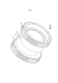
[0021] A Figura 1 é uma vista em perspectiva de uma modalidade de um mecanismo de pistão alternativo de acordo com a invenção.[0021] Figure 1 is a perspective view of one embodiment of an alternative piston mechanism according to the invention.
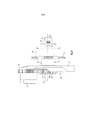
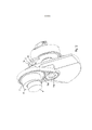
[0022] As Figuras 2 e 3 são vistas em perspectiva de uma parte da modalidade da Figura 1 em uma escala maior vista de lados diferentes.[0022] Figures 2 and 3 are perspective views of a part of the embodiment of Figure 1 on a larger scale seen from different sides.
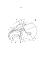
[0023] As Figuras 4 e 5 são similares às Figuras 2 e 3, mas ilustrando a parte que inclui o elemento de manivela.[0023] Figures 4 and 5 are similar to Figures 2 and 3, but illustrating the part that includes the crank element.
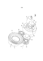
[0024] A Figura 6 é uma vista em perspectiva de uma parte de uma modalidade da parte, conforme mostrado nas Figuras 2 e 3.[0024] Figure 6 is a perspective view of a part of an embodiment of the part, as shown in Figures 2 and 3.
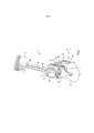
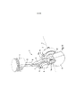
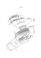
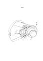
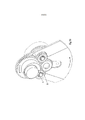
[0025] A Figura 7 é uma vista em perspectiva de uma parte de um motor de combustão interna, que é dotado de uma modalidade do mecanismo de acordo com a invenção.[0025] Figure 7 is a perspective view of a part of an internal combustion engine, which is provided with an embodiment of the mechanism according to the invention.
[0026] A Figura 8 é uma vista comparável a da Figura 7, mas mostrando uma modalidade alternativa, como visto de um lado diferente.[0026] Figure 8 is a view comparable to Figure 7, but showing an alternative embodiment, as seen from a different side.
[0027] A Figura 9 é uma vista lateral da modalidade, conforme mostrado nas Figuras 4 e 5.[0027] Figure 9 is a side view of the embodiment, as shown in Figures 4 and 5.
[0028] A Figura 10 é uma vista lateral da modalidade, conforme mostrado na Figura 7.[0028] Figure 10 is a side view of the embodiment, as shown in Figure 7.
[0029] A Figura 11 é uma vista similar a da Figura 1, mas mostrando uma modalidade alternativa.[0029] Figure 11 is a view similar to Figure 1, but showing an alternative embodiment.
[0030] A Figura 12 é uma vista em perspectiva de uma parte da modalidade da Figura 11 em uma escala maior.[0030] Figure 12 is a perspective view of a part of the embodiment of Figure 11 on a larger scale.
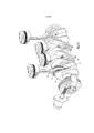
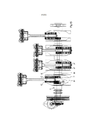
[0031] A Figura 13 é uma vista em perspectiva de um motor de combustão interna de multicilindros, que é dotado de uma modalidade de um mecanismo de pistão alternativo de acordo com a invenção.[0031] Figure 13 is a perspective view of a multi-cylinder internal combustion engine, which is provided with an embodiment of a reciprocating piston mechanism according to the invention.
[0032] A Figura 14 é uma vista similar a da Figura 13, mas sem mostrar o elemento de manivela.[0032] Figure 14 is a view similar to Figure 13, but without showing the crank element.
[0033] A Figura 15 é uma vista lateral da modalidade, conforme mostrado na Figura 14.[0033] Figure 15 is a side view of the embodiment, as shown in Figure 14.
[0034] A Figura 16 é uma vista em perspectiva de uma parte da modalidade, conforme mostrado na Figura 13.[0034] Figure 16 is a perspective view of a part of the embodiment, as shown in Figure 13.
[0035] As Figuras 17 a 20 são vistas similares a da Figura 4, em que um suporte é eliminado para ilustrar posições de diferentes partes sob condições operacionais.[0035] Figures 17 to 20 are views similar to Figure 4, in which a support is eliminated to illustrate positions of different parts under operating conditions.
[0036] A Figura 21 é uma vista em perspectiva de uma modalidade alternativa de um atuador.[0036] Figure 21 is a perspective view of an alternative embodiment of an actuator.
[0037] A Figura 22 é uma vista em perspectiva de uma modalidade alternativa de um atuador.[0037] Figure 22 is a perspective view of an alternative embodiment of an actuator.
[0038] A Figura 23 é uma vista em perspectiva de um motor de combustão interna de três cilindros, que é dotado de uma modalidade alternativa de um mecanismo de pistão alternativo de acordo com a invenção.[0038] Figure 23 is a perspective view of a three-cylinder internal combustion engine, which is provided with an alternative embodiment of an alternative piston mechanism according to the invention.
[0039] A Figura 24 é uma vista ampliada de uma parte da modalidade, conforme mostrado na Figura 23 em uma escala maior.[0039] Figure 24 is an enlarged view of a portion of the embodiment as shown in Figure 23 on a larger scale.
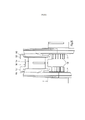
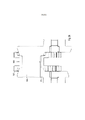
[0040] A Figura 25 é uma vista lateral e uma vista seccional parcial de uma parte de uma modalidade alternativa, conforme mostrado na Figura 15 em uma escala maior.[0040] Figure 25 is a side view and a partial sectional view of part of an alternative embodiment as shown in Figure 15 on a larger scale.
[0041] A Figura 26 é uma vista similar a da Figura 25, mas ilustrando a conexão de encaixe sob pressão entre o pino de manivela e o braço de manivela cooperante.[0041] Figure 26 is a view similar to Figure 25, but illustrating the press fit connection between the crank pin and the cooperating crank arm.
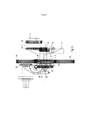
[0042] A Figura 1 mostra uma parte de uma modalidade de um mecanismo de pistão alternativo 1 de acordo com a invenção, que é adequada para um motor de combustão interna. O mecanismo de pistão alternativo 1 compreende um cárter 15, que suporta um elemento de manivela 2 através de mancais de elemento de manivela 3, veja as Figuras 4 e 5. O elemento de manivela 2 inclui um pino de manivela 4 e é girável com relação ao cárter 15 em torno de um eixo geométrico de eixo mecânico de manivela 5.[0042] Figure 1 shows a part of an embodiment of a reciprocating piston mechanism 1 according to the invention, which is suitable for an internal combustion engine. The reciprocating piston mechanism 1 comprises a
[0043] O mecanismo de pistão alternativo 1 compreende um elemento de manivela 6, que é montado rotacionalmente no pino de manivela 4. O elemento de manivela 6 é dotado de uma porção de mancal 7, que é disposta excentricamente com relação ao pino de manivela 4, veja a Figura 2. A porção de mancal 7 tem uma parede circunferencial externa, que suporta uma extremidade grande 8 de uma haste de conexão 9. Desse modo, a haste de conexão 9 é montada rotacionalmente no elemento de manivela 6 via sua extremidade grande 8. A haste de conexão 9 também inclui uma extremidade pequena 10 à qual um pistão 11 é conectado rotacionalmente.[0043] The reciprocating piston mechanism 1 comprises a
[0044] As Figuras 2 e 3 mostram uma parte da modalidade da Figura 1, como visto de lados diferentes. O elemento de manivela 2 e a haste de conexão 9 não são mostrados por razões de clareza. As Figuras 4 e 5 mostram a mesma parte, mas incluindo o elemento de manivela 2.[0044] Figures 2 and 3 show a part of the embodiment of Figure 1, as seen from different sides. Crank
[0045] O elemento de manivela 6 é dotado de uma engrenagem de elemento de manivela 12, que engata com duas engrenagens intermediárias 13. O elemento de manivela 6 e a engrenagem de elemento de manivela 12 podem ser feitos de uma peça, mas a engrenagem de elemento de manivela 12 pode ser pressionada sobre uma parte de base cilíndrica do elemento de manivela 6, igualmente. As engrenagens intermediárias 13 são montadas rotacionalmente no eixo de manivela 2 e seus eixos de rotação se estendem paralelo ao eixo geométrico do eixo mecânico de manivela 5. Cada uma das engrenagens intermediárias 13 também engatam com uma engrenagem auxiliar 14. A engrenagem auxiliar 14 é fixada a um eixo auxiliar 16. O eixo auxiliar 16 se estende concentricamente através do eixo de manivela 2 e é girável com relação ao eixo de manivela 2 em torno do eixo geométrico do eixo mecânico de manivela 5. Desse modo, o eixo auxiliar 16 é girável em torno de um eixo geométrico de um eixo mecânico auxiliar, que coincide substancialmente com o eixo geométrico de eixo mecânico de manivela 5. Como uma consequência, a linha central da engrenagem auxiliar 14 coincide com o eixo geométrico do eixo mecânico de manivela 5.[0045] The
[0046] As Figuras 1, 4 e 5 mostram que a engrenagem auxiliar 14, as engrenagens intermediárias 13 e a engrenagem de elemento de manivela 12 são montadas no mesmo lado de um braço de manivela 17 do eixo de manivela 2. Isso também pode ser visto na vista lateral da Figura 9. O braço de manivela 17 e o mancal de eixo de manivela adjacente 3 são integrados de modo que o eixo auxiliar 16 se estende através de ambos. Assim, o eixo auxiliar 16 se estende dentro de uma circunferência externa do mancal de eixo de manivela 3 Pode ser visto na Figura 1 que as engrenagens intermediárias 13 são dispostas em um lado do elemento de manivela 2, onde um contrapeso está localizado, o qual cria uma estrutura compacta.[0046] Figures 1, 4 and 5 show that the
[0047] Na modalidade conforme mostrado nas Figuras de 1 a 5, a engrenagem de elemento de manivela 12, as engrenagens intermediárias 13 e as engrenagens auxiliares 14 podem ser engrenagens externas. Devido a essa configuração, o mecanismo de pistão alternativo 1 pode ser construído de maneira compacta e é mais simples do que aqueles conhecidos na técnica.[0047] In the embodiment as shown in Figures 1 to 5, the
[0048] As dimensões das engrenagens podem ser selecionadas de modo que, sob condições operacionais, o elemento de manivela 6 gira na mesma direção que o elemento de manivela 2 e em metade de sua velocidade . A direção de rotação é definida com relação ao cárter. As direções e as velocidades de rotação são alcançadas quando a relação de engrenagens entre a engrenagem de elemento de manivela 12 e a engrenagem auxiliar 14 é dois e o eixo auxiliar 16 é mantido em uma posição angular constante com relação ao cárter 15. A fim de obter a relação de engrenagens desejada, é relevante que as engrenagens intermediárias 13 e a engrenagem auxiliar 14 estejam localizadas no mesmo lado do braço de manivela 17, uma vez que, na prática, o diâmetro da engrenagem auxiliar 14 é relativamente pequeno, o que levaria a um diâmetro pequeno do elemento de manivela 2 na localização da engrenagem auxiliar 14, se esta for montada rotacionalmente no elemento de manivela 2 no lado oposto do braço de manivela 17.[0048] The dimensions of the gears can be selected so that, under operating conditions, the
[0049] Deve ser notado que uma função das engrenagens intermediárias 13 é girar a engrenagem auxiliar 14 na direção correta de rotação em caso de aplicação de uma transmissão de engrenagens entre o elemento de manivela 6 e o eixo auxiliar 16. O número de dentes das engrenagens intermediárias 13 não é relevante para a relação de transmissão entre a engrenagem de elemento de manivela 12 e a engrenagem auxiliar 14.[0049] It should be noted that a function of the
[0050] A fim de ilustrar o funcionamento do mecanismo sob condições de operação, as Figuras 17 a 20 mostram quatro posições diferentes do eixo de manivela 2 com relação ao cárter 15. Por razões ilustrativas, o elemento de manivela 6 e a engrenagem auxiliar 14 são dotados de marcas A, B, veja a Figura 17. A direção de rotação do eixo de manivela 2 e do elemento de manivela 6 com relação ao cárter 15 é mostrada por respectivas setas. A Figura 17 mostra a posição do centro morto superior. Na posição, conforme mostrado na Figura 18, o eixo de manivela 2 girou no sentido anti-horário por 180° com relação ao cárter. Pode ser visto que a engrenagem auxiliar 14 manteve sua posição angular, enquanto a engrenagem de elemento de manivela 12 também girou no sentido anti-horário com relação ao cárter 15, mas por um ângulo de 90°. As Figuras 19 e 20 mostram outras etapas de rotação do eixo de manivela 2 através de etapas de 180°. As Figuras 17 a 20 mostram que duas rotações completas do eixo de manivela 2 correspondem a uma rotação completa do elemento de manivela 6 , conforme definido com relação ao eixo de manivela 2.[0050] In order to illustrate the operation of the mechanism under operating conditions, Figures 17 to 20 show four different positions of the
[0051] O mecanismo de pistão alternativo 1, conforme mostrado nas Figuras 1 a 5 proporciona a oportunidade de ajustar o centro morto superior do pistão 11, e portanto sua relação de compressão por meio da mudança da posição angular do eixo auxiliar 16 com relação ao cárter 15. Nas Figuras 1 a 5 e, mais especificamente, na Figura 3, pode ser visto que o mecanismo 1 é dotado de uma mola de torção 18, que é fixada no eixo auxiliar 16, por um lado, e no cárter 15, por outro lado. Um anel de controle 19 é preso ao eixo auxiliar 16, por exemplo, por meio de prensagem e dotado de reentrâncias 20 que estão localizadas em distâncias angulares mútuas em torno do eixo geométrico do eixo mecânico de manivela 5. O mecanismo 1 também compreende um atuador 21, que controla um pino (não mostrado, que se encaixa em cada uma das reentrâncias 20. Sob condições estáveis de funcionamento, o pino sustenta o anel de controle 19 em uma posição fixa com relação ao cárter 15 e o mecanismo 1 funciona em uma relação de compressão fixa.[0051] The alternative piston mechanism 1, as shown in Figures 1 to 5, provides the opportunity to adjust the top dead center of the
[0052] É concebível eliminar o atuador 21, incluindo o pino, o que significa que o eixo auxiliar 16 não é bloqueável com o cárter 15. Naquele caso, sob condições de operação, o eixo auxiliar 16 pode vibrar em direção rotacional devido à presença da mola de torção 18 no eixo auxiliar 16. Em carga superior devido às forças de combustão aumentadas, a força de ação e reação entre o eixo auxiliar 16 e a mola de torção 18, isto é, o equilíbrio natura, fica em um nível mais alto. Isso significa que a mola de torção 18 será comprimida e o eixo auxiliar 16 é girado por um certo ângulo com relação ao cárter 15. Em uma carga inferior, o efeito oposto é obtido. Como uma consequência, um ajuste automático da posição angular do eixo auxiliar 16 é alcançado;[0052] It is conceivable to eliminate the
[0053] Em caso de aplicação do mecanismo 1 em um motor de combustão interna, a modalidade, conforme mostrado na Figura 3, funciona como segue. Se uma relação de compressão diferente for desejada, o pino é retraído para fora da reentrância correspondente 20 do atuador 21, com uma carga de motor predeterminada. Por exemplo, se uma relação de compressão inferior for desejada, isto é, comutando para uma carga de motor superior, a força rotacional real relativamente alta do eixo auxiliar 16 na mola de torção 18 excede a força de mola da mola de torção 18, fazendo com que o eixo auxiliar 16, incluindo o anel de controle 19, gire na direção da força resultante. Se o pino for deslocado de volta em direção ao anel de controle 19, o pino encaixa em outra reentrância 20. Se o anel de controle 19 for girado na direção oposta, a fim de se obter uma relação de compressão maior, isto é, comutando para uma carga de motor menor, a força rotacional real do eixo auxiliar 16 na mola 18 na carga de motor correspondente, relativamente baixa, é menor do que a força de mola da mola de torção 18, portanto, girando o anel de controle 19 para a direção oposta. O anel de controle 19 pode, então, ser fixado com relação ao cárter 15 por meio de inserção do pino na reentrância 20 correspondente.[0053] In case of application of mechanism 1 in an internal combustion engine, the modality, as shown in Figure 3, works as follows. If a different compression ratio is desired, the pin is retracted out of the
[0054] Deve ser notado que o atuador 21 pode ser controlado elétrica e hidraulicamente ou de forma semelhante. Além disso, a substancialmente circunferencial do anel de controle 19 pode ser parte de um mancal a fim de suportar o anel de controle 19 pelo cárter 15. O cárter 15 pode portar o anel de controle 19 por meio de um rolamento de esferas 19a, veja a Figura 10, mas mancais alternativos são concebíveis.[0054] It should be noted that the
[0055] A posição angular do eixo auxiliar 16 é monitorada por um sensor 22, que pode ser um potenciômetro simples. O sensor é montado no cárter 15. O sinal do sensor 22 é uma indicação da relação de compressão real.[0055] The angular position of the
[0056] A Figura 22 mostra uma modalidade alternativa de um atuador 38 para bloquear o anel de controle 19 em uma posição fixa com relação ao cárter 15, de modo que o mecanismo 1 funciona em uma relação de compressão fixa. Nesta modalidade, o anel de controle 19 é fixado ao eixo auxiliar 16 em sua direção rotacional. A mola de torção 18 é fixada ao eixo auxiliar 16 na localização P, como indicado na Figura 22 e no cárter 15, perto do sensor 22. O atuador 38 compreende um eletroímã 39, que é preso ao cárter 15 e coberto por uma cobertura de ímã 40. Com a ligação da corrente elétrica através do eletroímã 39, o anel de controle 19 é puxado contra a cobertura de ímã 40, de modo que o anel de controle 19, incluindo o eixo auxiliar 16, é mantido em uma posição fixa com relação ao cárter 15. As superfícies de contato cooperantes da cobertura de ímã 40 e o anel de controle 19 podem ser dotados de matéria de atrito. A distância axial entre as superfícies de contato cooperantes, em caso de o eletroímã não ser ativado, é muito pequena, por exemplo, menor do que 0,2 mm de modo que o deslocamento axial do anel de controle 19 com relação ao eixo auxiliar 16 ou ao anel de controle 19, incluindo o eixo auxiliar 16, com relação ao cárter 15 é muito pequeno. Deve ser notado que a comutação entre alta e baixa carga e altas e baixas relações de compressão por meio da mola de torção 18 pode ser realizada de maneira similar, conforme explicado aqui antes em relação à modalidade de acordo com as Figuras de 1 a 5.[0056] Figure 22 shows an alternative embodiment of an
[0057] Na modalidade conforme mostrado nas Figuras de 1 a 5, a engrenagem de elemento de manivela 12 e a engrenagem auxiliar 14 estão localizadas perto uma da outra dentro do mesmo plano. A maior parte dos mecanismos de pistão tem cursos de pistão, que podem não permitir a configuração, conforme mostrado nas Figuras de 1 a 5. Nesse caso, as engrenagens intermediárias 13 podem ser prolongadas, de modo que se estendam além da engrenagem de elemento de manivela em pelo menos uma direção da mesma, enquanto a engrenagem auxiliar engata com as engrenagens intermediárias 13 nas suas porções estendidas, de modo que a engrenagem auxiliar 14 sobrepõe, parcialmente, a engrenagem de elemento de manivela 12. Isso é mostrado na Figura 6, onde a engrenagem auxiliar 14 está localizada em frente da engrenagem de elemento de manivela 12. Nesta modalidade, a soma dos diâmetros externos da engrenagem de elemento de manivela 12 e a engrenagem auxiliar 14 é maior do que um curso de pistão, enquanto as engrenagens 12 a 14 estão localizadas no mesmo lado do braço de manivela 17.[0057] In the embodiment as shown in Figures 1 to 5, the
[0058] Além disso, a Figura 6 mostra que o elemento de manivela 6 compreende uma segunda engrenagem de elemento de manivela 12' para acionamento de outros elementos de manivela, em caso de um mecanismo de pistão alternativo de multicilindros. A engrenagem de elemento de manivela 12 e a segunda engrenagem de elemento de manivela 12' estão localizadas em porções extremas opostas do elemento de manivela 6. A extremidade grande 8 da haste de conexão 9 é disposta entre a engrenagem de elemento de manivela 12 e a segunda engrenagem de elemento de manivela 12'. As Figuras 13 a 16 mostram uma modalidade de um motor de combustão interna de multicilindros, em que a segunda engrenagem de elemento de manivela 12' aciona engrenagens de elementos de manivela que são proporcionadas em outros pinos de manivela. A segunda engrenagem de elemento de manivela 12' engata com uma outra engrenagem auxiliar 34, que é fixada a um eixo 35 que se estende através de um braço de manivela adjacente 17' e/ou braços de manivela e/ou mancais principais e em que o eixo 35 outra engrenagem auxiliar 36 é fixado, que aciona uma outra engrenagem de elemento de manivela 37 de um pino de manivela adjacente. As Figuras 6 e 13 a 16 mostram que a largura da engrenagem de elemento de manivela 12 é menor do que a da segunda engrenagem de elemento de manivela 12'. Isso é possível uma vez que a engrenagem de elemento de manivela 12 engata com duas engrenagens intermediárias 13, enquanto a segunda engrenagem de elemento de manivela 12' engata com apenas uma outra engrenagem auxiliar 34.[0058] Furthermore, Figure 6 shows that the
[0059] O diâmetro da engrenagem de elemento de manivela 12 que engata com as engrenagens intermediárias 13 pode ser diferente do diâmetro da segunda engrenagem de elemento de manivela 12' e as outras engrenagens de elementos de manivela 37. Isso pode ser desejado por razões de acondicionamento no braço de manivela 17. Nesse caso, uma engrenagem de elemento de manivela 12 relativamente pequena pode ser prensada na parte de base cilíndrica do elemento de manivela 6. Com relação à segunda engrenagem de elemento de manivela 12' e às engrenagens de elementos de manivela 37 adicionais e às outras engrenagens auxiliares 36 é relevante que relações de transmissão idênticas sejam aplicadas.[0059] The diameter of the
[0060] As Figuras 7 e 8 mostram um meio de acionamento da engrenagem auxiliar 14 para ajustar a relação de compressão do mecanismo 1 de maneira contínua em lugar de por meio de etapas distintas, conforme descrito em relação à modalidade que é mostrada nas Figuras 3 e 5. O meio de acionamento alternativo compreende um atuador 23 na forma de um motor elétrico, que é capaz de acionar a engrenagem auxiliar 14 via um elemento sem fim 24 e uma engrenagem sem fim 25, que é fixada ao eixo auxiliar 16, mas outros meios de acionamento alternativos são concebíveis. Com a rotação do elemento sem fim 24, o centro morto superior e o inferior do pistão 11 podem ser influenciados. Na modalidade conforme mostrado nas Figuras 7 e 8, a mola de torção 18 poderia ser omitida. Contudo, a mola de torção 18 pode ser apropriada a fim de equilibrar a força real da engrenagem sem fim 25 no elemento sem fim 24, portanto, requerendo energia relativamente limitada para acionar o elemento sem fim 24. A força real da engrenagem sem fim 25 no elemento sem fim 24 pode ser causada por forças de combustão em caso de um motor de combustão interna.[0060] Figures 7 and 8 show a means of actuating the
[0061] Uma vantagem da aplicação de um meio de acionamento incluindo o elemento sem fim 24 é que ele proporciona a oportunidade para determinar a força rotacional real do eixo auxiliar 16 no elemento sem fim 24. Em caso de um motor de combustão interna essa força está relacionada diretamente com a pressão de combustão no pistão 11. A força pode ser medida por um sensor de força ou de pressão no elemento sem fim 24, por exemplo, um elemento piezoelétrico ou semelhante. O sensor pode ser incorporado nos mancais do elemento sem fim 24. O sinal pode ser usado para detecção de falha na ignição, por exemplo.[0061] An advantage of applying a drive means including the
[0062] Deve ser notado que o eixo auxiliar 16 proporciona a oportunidade para medir as forças de combustão em maneiras alternativas, por exemplo, por meio de medição de torque do eixo auxiliar 16.[0062] It should be noted that the
[0063] As Figuras 7 e 8 também mostram elementos de transferência para acionamento de partes auxiliar em caso de um motor de combustão interna. Ambas as modalidades nas Figuras 7 e 8 têm uma engrenagem de tomada de energia 26, que é presa ao eixo de manivela 2. A engrenagem de tomada de energia 26 engata com uma primeira engrenagem de acionamento 27, por exemplo, para acionamento de uma bomba de óleo e uma segunda engrenagem de acionamento 28, por exemplo, para acionamento de um eixo de came; A modalidade da Figura 7 mostra que a segunda engrenagem de acionamento 28 é montada em um eixo comum com uma roda dentada 29 para acionamento de uma corrente. A modalidade da Figura 8 mostra que a segunda engrenagem de acionamento 28 é montada em um eixo comum com uma polia 30 para acionamento de uma correia. Em uma modalidade alternativa, a polia 30 ou a roda dentada 29 pode ser substituída por uma roda para acionamento de uma correia dentada. Uma vez que a polia 30 e a roda dentada 29 estão localizadas em um eixo mecânico que se estende paralelo ao eixo de manivela 2, o mecanismo 1 pode ser construído compacto na direção longitudinal do eixo de manivela 2 , apesar da presença de partes do meio de acionamento para girar a engrenagem auxiliar 14 na extremidade do eixo de manivela 2 .[0063] Figures 7 and 8 also show transfer elements for driving auxiliary parts in the case of an internal combustion engine. Both embodiments in Figures 7 and 8 have a power take-
[0064] Essa estrutura também é mostrada na modalidade do mecanismo 1 de um motor de combustão interna de três cilindros, conforme representado na Figura 23. Nesse caso, a engrenagem de tomada de energia 26 engata com a primeira engrenagem de acionamento 27 que é agora montada em um eixo de equilíbrio 41, junto com a polia 30. Deve ser notado que essa estrutura é aplicável a motores que têm um número diferente de cilindros.[0064] This structure is also shown in the embodiment of mechanism 1 of a three-cylinder internal combustion engine, as shown in Figure 23. In this case, the power take-
[0065] Na modalidade, conforme mostrado na Figura 23, o diâmetro da engrenagem de elemento de manivela 12 é menor do que da segunda engrenagem de elemento de manivela 12' e das outras engrenagens de elementos de manivela 37. Isso proporciona a oportunidade para dispor as engrenagens 12 a 14 dentro de um plano comum, que é mostrado na Figura 24. A largura da engrenagem de elemento de manivela 12, porém, é maior do que a da segunda engrenagem de elemento de manivela 12' e a das outras engrenagens de elementos de manivela 37. Além disso, o diâmetro de uma porção do pino de manivela 4 na engrenagem de elemento de manivela 12 é menor do que em uma porção do pino de manivela 4 na segunda engrenagem de elemento de manivela 12' e o diâmetro do pino de manivela 4 nas outras engrenagens de elementos de manivela 37. Também é concebível que o diâmetro do pino de manivela 4 em ambas, a engrenagem de elemento de manivela 12 e a segunda engrenagem de elemento de manivela 12' seja o mesmo, mas menor do que o do pino de manivela 4 nas outras engrenagens de elementos de manivela 37. Se o diâmetro da porção de mancal 7 do elemento de manivela 6 também for relativamente pequeno a extremidade grande de sua haste de conexão cooperante também pode ser menor do que a das outras hastes de conexão.[0065] In the embodiment, as shown in Figure 23, the diameter of the
[0066] Devido ao diâmetro relativamente pequeno do pino de manivela 4 na engrenagem de elemento de manivela 12, a conexão entre o pino de manivela 4 e o braço de manivela 17 pode ser relativamente menos forte, o que poderia causar uma problema uma vez que a conexão é destinada a ser um encaixe sob pressão. Contudo, na prática, isso não é um problema pelas razões a seguir.[0066] Due to the relatively small diameter of the
[0067] O eixo de manivela 2, conforme mostrado na Figura 23, é feito por meio de três encaixes sob pressão; dois deles podem ser vistos na Figura 23 e são indicados por X e Y, respectivamente, onde os respectivos pinos de manivela 4 são prensados em respectivos furos dos braços de manivela 17 correspondentes. A porção do eixo de manivela 2 entre os encaixes sob pressão X e Y pode ser feita de uma peça. A Figura 23 mostra que o diâmetro do pino de manivela 4 no encaixe sob pressão X tem um diâmetro menor do que o pino de manivela 4 no encaixe sob pressão Y. Na prática, a força que é guiada através do eixo de manivela 2 no encaixe sob pressão X é menor do que no encaixe sob pressão Y uma vez que de carga, ou volante, do motor de combustão interna está localizada na extremidade do eixo de manivela 2 oposta à polia 30. O encaixe sob pressão X guia a força para o eixo de equilíbrio 41 e para a polia 30, incluindo, opcionalmente, dispositivos auxiliares. Portanto, é permissível que o pino de manivela 4 no elemento de manivela 6 tenha um diâmetro menor do que o dos outros pinos de manivela 4.[0067] The
[0068] A Figura 9 mostra uma vista lateral da modalidade conforme mostrado nas Figuras 4 e 5. Pode ser visto que as engrenagens 12 a 14 estão localizadas, parcialmente, em uma reentrância do braço de manivela 17. Isso proporciona a oportunidade para minimizar o comprimento do mecanismo 1, como visto ao longo do eixo de manivela 2 .[0068] Figure 9 shows a side view of the embodiment as shown in Figures 4 and 5. It can be seen that the
[0069] A Figura 10 mostra uma vista lateral da modalidade, conforme mostrado na Figura 7. Pode ser visto que nesta modalidade as engrenagens 12 a 14 não estão localizadas dentro de um plano comum, conforme explicado em relação às modalidades das Figuras 6 e 24. A engrenagem auxiliar 14 sobrepõe parcialmente a engrenagem de elemento de manivela 12 como vista em uma direção ao longo de suas linhas centrais.[0069] Figure 10 shows a side view of the embodiment, as shown in Figure 7. It can be seen that in this embodiment the
[0070] Fazendo referência à modalidade conforme mostrado na Figura 4, pode ser visto que as engrenagens intermediárias 13 são montadas rotacionalmente no braço de manivela 17 do eixo de manivela 2 . Nesse caso, as engrenagens intermediárias 13 são giráveis em respectivos eixos intermediários 13a via mancais deslizantes, mancais de agulha ou semelhantes (não mostrados), eixos intermediários 13a que são prensados em um suporte 31. Os eixos intermediários 13a encaixam em respectivos furos no braço de manivela 17 e são fixados ao eixo de manivela 2. Com a montagem do mecanismo 1, os eixos intermediários 13a são prensados no eixo de manivela 2, então, as engrenagens intermediárias 13 são montadas nos eixos intermediários 13a, após o que o suporte 31 é prensado nos eixos intermediários 13a e fixado no braço de manivela 17 através de um parafuso 32. O suporte 31 também impede o deslocamento da engrenagem auxiliar 14 em uma direção para longe do braço de manivela 17. Na modalidade conforme mostrado na Figura 24 pode ser visto que o suporte 31 tem uma forma diferente. É fixado ao braço de manivela 17 através de dois parafusos 32.[0070] Referring to the embodiment as shown in Figure 4, it can be seen that the
[0071] As Figuras 11 e 12 mostram uma modalidade alternativa do mecanismo 1 de acordo com a invenção. Partes que são similares àquelas nas modalidades conforme descrito aqui antes são indicadas por sinais de referência correspondentes. Neste caso, a engrenagem de elemento de manivela 12 e a engrenagem auxiliar 14 são substituídas por respectivas rodas 12a e 14a para acionamento de uma correia dentada 33. Essa transmissão também pode ser uma correia alternativa ou uma combinação de rodas dentadas e uma corrente.[0071] Figures 11 and 12 show an alternative embodiment of the mechanism 1 according to the invention. Parts that are similar to those in embodiments as described hereinabove are indicated by corresponding reference signs. In this case, the
[0072] A Figura 21 mostra um elemento de manivela 6 alternativo, que é adequado para um mecanismo de pistão alternativo tendo uma disposição em V, por exemplo, um motor-V. O elemento de manivela 8 compreende duas engrenagens de elementos de manivela 12. Além disso, o elemento de manivela 6 é dotado de duas porções de mancal 7, que estão em ângulo com relação um ao outro em torno da linha central do elemento de manivela 6. Devido a essa configuração, os pistões correspondentes alcançam seus respectivos centros mortos superiores em diferentes ângulos do elemento de manivela.[0072] Figure 21 shows an
[0073] A Figura 25 mostra uma parte do elemento de manivela de um motor de multicilindros, que é comparável com a modalidade conforme mostrado na Figura 15. Duas outras engrenagens auxiliares 136 engatam com respectivas engrenagens de elementos de manivela 137 do elemento de manivela 106 correspondente que é montado rotacionalmente no pino de manivela 104 correspondente, A fim de manter o eixo de manivela 2 tão forte quanto possível e construir de maneira compacta o diâmetro interno do elemento de manivela 106 é ampliado em uma porção extrema. Isso significa que outras engrenagens de elementos de manivela 137 se projetam parcialmente além da porção cilíndrica do pino de manivela 104 em sua direção longitudinal, que contata a extremidade grande da haste de conexão cooperante. De fato, o elemento de manivela 106 é dotado de cavidades centrais 140 em suas porções extremas para recebimento de porções de transição do eixo de manivela 2 que estão localizadas entre os respectivos braços de manivela 17 e a porção cilíndrica do pino de manivela 104, porções de transição que têm um diâmetro maior do que a porção cilíndrica do pino de manivela 104.[0073] Figure 25 shows a part of the crank element of a multi-cylinder engine, which is comparable with the embodiment as shown in Figure 15. Two other
[0074] Deve ser notado que, nas modalidades conforme aqui antes descrito, o diâmetro interno do pino de manivela 4 pode ser aumentado em uma porção extrema, de modo que uma porção circunferencial externa da engrenagem de elemento de manivela 12 se projeta pelo menos parcialmente além da porção cilíndrica do pino de manivela 4 em sua direção longitudinal.[0074] It should be noted that, in the embodiments as described hereinbefore, the inner diameter of the
[0075] Uma engrenagem de elemento de manivela que se projeta axialmente 12, 137 também é vantajosa para maximizar o comprimento da conexão de encaixe sob pressão entre o braço de manivela 17 adjacente e o pino de manivela 4, 104, que é ilustrado na Figura 26, no lado esquerdo do pino de manivela 104. Em geral, o comprimento do encaixe sob pressão na direção axial do pino de manivela, a e é, de preferência, é maior do que 40% do diâmetro do pino de manivela cooperante.[0075] An axially projecting crank
[0076] Deve ser notado que características diferentes das modalidades, conforme aqui antes descrito, podem ser combinadas.[0076] It should be noted that different features of the embodiments, as described hereinbefore, may be combined.
[0077] Do precedente, estará claro que a invenção proporciona um mecanismo de pistão alternativo relativamente simples, que proporciona a possibilidade de planejar uma modalidade compacta do mecanismo.[0077] From the foregoing, it will be clear that the invention provides a relatively simple alternative piston mechanism, which provides the possibility of designing a compact embodiment of the mechanism.
[0078] A invenção não está limitada às modalidades mostradas nos desenhos e aqui antes descritas quais podem ser variadas de diferentes maneiras, dentro do escopo das reivindicações e seus equivalentes técnicos. Por exemplo, o mecanismo de pistão alternativo pode ser estendido para mecanismos maiores tendo mais pistões do que as modalidades conforme aqui antes descrito. Em uma modalidade alternativa, o elemento de manivela pode ser cilíndrico, em lugar de excêntrico, o que parece resultar em perdas menores de atrito do que em um mecanismo convencional não tendo elemento de manivela e transmissão de engrenagens para acionamento do elemento de manivela.[0078] The invention is not limited to the embodiments shown in the drawings and described hereinbefore, which can be varied in different ways, within the scope of the claims and their technical equivalents. For example, the reciprocating piston mechanism can be extended to larger mechanisms having more pistons than the embodiments as described hereinbefore. In an alternative embodiment, the crank element may be cylindrical, rather than eccentric, which appears to result in lower friction losses than in a conventional mechanism having no crank element and gear transmission for actuating the crank element.
Claims (14)
Applications Claiming Priority (3)
| Application Number | Priority Date | Filing Date | Title |
|---|---|---|---|
| EP12152309.6 | 2012-01-24 | ||
| EP12152309.6A EP2620614B1 (en) | 2012-01-24 | 2012-01-24 | A reciprocating piston mechanism |
| PCT/EP2013/051333 WO2013110700A1 (en) | 2012-01-24 | 2013-01-24 | A reciprocating piston mechanism |
Publications (3)
| Publication Number | Publication Date |
|---|---|
| BR112014017873A2 BR112014017873A2 (en) | 2017-06-20 |
| BR112014017873A8 BR112014017873A8 (en) | 2017-07-11 |
| BR112014017873B1 true BR112014017873B1 (en) | 2022-10-18 |
Family
ID=47603746
Family Applications (1)
| Application Number | Title | Priority Date | Filing Date |
|---|---|---|---|
| BR112014017873-9A BR112014017873B1 (en) | 2012-01-24 | 2013-01-24 | ALTERNATIVE PISTON MECHANISM |
Country Status (9)
| Country | Link |
|---|---|
| US (1) | US10234006B2 (en) |
| EP (2) | EP2620614B1 (en) |
| JP (1) | JP6305347B2 (en) |
| KR (1) | KR102074649B1 (en) |
| CN (1) | CN104204455B (en) |
| BR (1) | BR112014017873B1 (en) |
| CA (1) | CA2861277C (en) |
| RU (1) | RU2623136C2 (en) |
| WO (1) | WO2013110700A1 (en) |
Families Citing this family (44)
| Publication number | Priority date | Publication date | Assignee | Title |
|---|---|---|---|---|
| CN102066719B (en) * | 2009-07-15 | 2014-05-21 | 戈梅克赛斯股份有限公司 | A reciprocating piston mechanism |
| EP2620614B1 (en) | 2012-01-24 | 2016-11-09 | Gomecsys B.V. | A reciprocating piston mechanism |
| EP2873834A1 (en) * | 2013-11-13 | 2015-05-20 | Gomecsys B.V. | A method of assembling and an assembly of a crankshaft and a crank member |
| EP2902603A1 (en) * | 2014-01-31 | 2015-08-05 | Gomecsys B.V. | An internal combustion engine including variable compression ratio |
| EP2905449B1 (en) * | 2014-02-11 | 2018-05-09 | Gomecsys B.V. | An internal combustion engine including variable compression ratio and a method of operating the engine |
| EP2907986B1 (en) * | 2014-02-18 | 2017-05-03 | Gomecsys B.V. | A four-stroke internal combustion engine with variable compression ratio |
| EP2930329B1 (en) * | 2014-04-08 | 2016-12-28 | Gomecsys B.V. | An internal combustion engine including variable compression ratio |
| FR3022299A1 (en) * | 2014-06-12 | 2015-12-18 | Peugeot Citroen Automobiles Sa | INTERNAL COMBUSTION ENGINE WITH VARIABLE COMPRESSION RATIO |
| DE102014216533A1 (en) | 2014-08-20 | 2016-02-25 | Schaeffler Technologies AG & Co. KG | Device for changing a compression ratio of a cylinder unit of a reciprocating internal combustion engine |
| CN104832279B (en) * | 2015-01-08 | 2018-01-02 | 武汉富国发动机科技有限公司 | New energy-saving IC engine |
| FR3035682B1 (en) * | 2015-04-28 | 2017-04-28 | Peugeot Citroen Automobiles Sa | INTERNAL COMBUSTION ENGINE OF A MOTOR VEHICLE WITH A SYSTEM OF VARIATION IN THE RATE OF COMPRESSION |
| FR3035681B1 (en) * | 2015-04-28 | 2017-04-28 | Peugeot Citroen Automobiles Sa | ECCENTRIC PIECE FOR A COMPRESSION RATE SYSTEM OF A THERMAL ENGINE |
| FR3036146B1 (en) * | 2015-05-11 | 2017-05-26 | Peugeot Citroen Automobiles Sa | ECCENTRIC PIECE FOR A COMPRESSION RATE SYSTEM OF A THERMAL ENGINE |
| EP3103986B1 (en) | 2015-06-08 | 2018-01-31 | Gomecsys B.V. | A four-stroke internal combustion engine including variable compression ratio and a vehicle |
| CA2993039C (en) * | 2015-07-21 | 2021-11-16 | Nissan Motor Co., Ltd. | Internal combustion engine |
| CN105156620B (en) * | 2015-07-24 | 2018-04-17 | 李云峰 | A kind of crankmotion switching mechanism |
| DE102015112690B4 (en) * | 2015-08-03 | 2023-04-20 | Ovalo Gmbh | Actuator system, in particular for coupling to the adjustment shaft of an internal combustion engine for setting the expansion stroke and/or the compression ratio |
| FR3042815B1 (en) * | 2015-10-22 | 2019-08-02 | Psa Automobiles Sa. | THERMAL MOTOR PROVIDED WITH A SYSTEM OF VARIATION OF THE COMPRESSION RATE |
| FR3042816B1 (en) | 2015-10-22 | 2017-12-08 | Peugeot Citroen Automobiles Sa | THERMAL MOTOR PROVIDED WITH A SYSTEM OF VARIATION OF THE COMPRESSION RATE |
| FR3043720B1 (en) | 2015-11-17 | 2019-11-08 | MCE 5 Development | VARIABLE VOLUMETRIC RATIO ENGINE |
| CN105605081A (en) * | 2016-03-18 | 2016-05-25 | 蔡建龙 | Engine crankshaft |
| CN105673795A (en) * | 2016-03-23 | 2016-06-15 | 刘有双 | Accelerator |
| FR3050234B1 (en) * | 2016-04-19 | 2021-01-15 | Peugeot Citroen Automobiles Sa | KIT FOR THERMAL ENGINE COMPRESSION RATE VARIATION SYSTEM |
| FR3052495B1 (en) * | 2016-06-09 | 2020-01-10 | Peugeot Citroen Automobiles Sa | HEAT ENGINE WITH IMPROVED COMPRESSION RATE VARIATION SYSTEM |
| US10119463B2 (en) * | 2016-12-09 | 2018-11-06 | Mark Albert Sokalski | Infinitely variable compression ratio and single stroke length mechanism or dual stroke length mechanism of reciprocating 2-cycle or 4-cycle internal combustion engine |
| JP2018105159A (en) * | 2016-12-22 | 2018-07-05 | いすゞ自動車株式会社 | engine |
| DE102017200918B4 (en) | 2017-01-20 | 2022-10-06 | Bayerische Motoren Werke Aktiengesellschaft | Crank mechanism for a reciprocating internal combustion engine |
| JP7101459B2 (en) * | 2017-04-26 | 2022-07-15 | Ntn株式会社 | Electric actuator |
| WO2018237321A1 (en) * | 2017-06-23 | 2018-12-27 | Straight Line Drive, Inc. | A system and method for converting rotating motion into linear motion |
| DE102018201988B3 (en) | 2018-02-08 | 2019-05-29 | Audi Ag | Connecting rod for an internal combustion engine and corresponding internal combustion engine |
| EP3540270A1 (en) | 2018-03-12 | 2019-09-18 | Gomecsys B.V. | A gear train and an internal combustion engine |
| EP3608523A1 (en) * | 2018-08-09 | 2020-02-12 | Gomecsys B.V. | An eccentric member and a v-type internal combustion engine |
| DE102018128524B4 (en) | 2018-11-14 | 2022-09-22 | Bayerische Motoren Werke Aktiengesellschaft | Compression ratio changing device, reciprocating internal combustion engine and working device |
| EP3719339A1 (en) | 2019-04-05 | 2020-10-07 | Gomecsys B.V. | An apparatus including an adjusting system for adjusting a rotational position of a shaft with respect to a shaft holding member |
| EP3726023A1 (en) | 2019-04-17 | 2020-10-21 | Gomecsys B.V. | An internal combustion engine |
| RU2716521C1 (en) * | 2019-07-30 | 2020-03-12 | Общество с ограниченной ответственностью "Завод дозировочной техники "Ареопаг" | Piston device of pump |
| EP3808955A1 (en) | 2019-10-15 | 2021-04-21 | Gomecsys B.V. | An internal combustion engine with variable compression ratio |
| CN111022603B (en) * | 2020-01-07 | 2021-07-20 | 重庆大学 | Staggered planetary roller screw speed reducer |
| US11131240B1 (en) * | 2020-05-15 | 2021-09-28 | GM Global Technology Operations LLC | Engine assembly including a force splitter for varying compression ratio using an actuator |
| GEP20227367B (en) * | 2020-08-06 | 2022-03-25 | Ramzan Goytemirov | Engine having compression ratio control mechanism |
| CN112504054A (en) * | 2020-11-24 | 2021-03-16 | 重庆钧顶机械制造有限公司 | Timing gear meshing runout degree gauge for crank link mechanism |
| DE102021103790A1 (en) | 2021-02-18 | 2022-08-18 | Bayerische Motoren Werke Aktiengesellschaft | Adjusting device for setting a variable compression ratio of a reciprocating engine, motor vehicle and method |
| US11255374B1 (en) * | 2021-03-04 | 2022-02-22 | VenTec LLC | Engine crank |
| EP4086443A1 (en) | 2021-05-05 | 2022-11-09 | Gomecsys B.V. | An internal combustion engine and a method of operating the internal combustion engine |
Family Cites Families (79)
| Publication number | Priority date | Publication date | Assignee | Title |
|---|---|---|---|---|
| FR636243A (en) * | 1928-04-04 | |||
| DE181913C (en) | ||||
| DD242077A (en) | ||||
| US460642A (en) * | 1891-10-06 | Variable crank-motion | ||
| DE164819C (en) * | 1904-08-02 | 1905-11-16 | ||
| US1207429A (en) * | 1916-01-04 | 1916-12-05 | James Currie Morison | Means for equalizing piston displacement. |
| GB150291A (en) | 1917-12-13 | 1921-11-18 | Clerget Blin & Cie | Improvements in or relating to explosion engines with variable compression |
| DE329861C (en) * | 1918-04-12 | 1920-12-04 | Motorenfabrik Oberursel A G | Elevation control for rotary engines of aircraft |
| GB173252A (en) | 1920-07-19 | 1921-12-19 | Charles Kane Salisbury | Improvements in internal combustion engines |
| US1553009A (en) | 1923-07-23 | 1925-09-08 | Stuke Ernest | Engine |
| DE488059C (en) | 1925-05-16 | 1929-12-18 | Louis Damblanc | Internal combustion engine with variable piston stroke |
| US1767352A (en) | 1927-03-26 | 1930-06-24 | Damblanc Louis | Crank shaft |
| US1964096A (en) * | 1931-11-21 | 1934-06-26 | Emmitt M Tucker | Connecting rod mounting |
| FR861611A (en) | 1939-07-29 | 1941-02-13 | Internal combustion engine with variable displacement and automatic compression ratio | |
| US2271766A (en) | 1940-05-06 | 1942-02-03 | Harry A Huebotter | Engine |
| US2369747A (en) * | 1942-07-30 | 1945-02-20 | Elvin R Munn | Engine |
| FR986605A (en) * | 1943-11-23 | 1951-08-02 | Device for varying, in operation, the compression ratio of an engine | |
| FR1014314A (en) | 1946-04-10 | 1952-08-13 | Variable displacement internal combustion engine | |
| GB1094649A (en) | 1963-12-16 | 1967-12-13 | Henry Eddington Roberts | Improvements in or relating to machines having a reciprocating member coupled to a rotatable member |
| US3686972A (en) * | 1970-05-28 | 1972-08-29 | Edward M Mcwhorter | Internal combustion engine variable throw crankshaft |
| JPS5247093B2 (en) | 1972-05-10 | 1977-11-30 | ||
| US3861239A (en) * | 1972-06-05 | 1975-01-21 | Edward M Mcwhorter | Internal combustion engine combustion control crankshaft |
| US3886805A (en) * | 1974-04-09 | 1975-06-03 | Ivan Koderman | Crank gear for the conversion of a translational motion into rotation |
| US4152955A (en) * | 1975-01-02 | 1979-05-08 | Mcwhorter Edward M | Engine compound crankshaft |
| US4073196A (en) * | 1976-08-13 | 1978-02-14 | Gilbert T. Hendren, Jr. | Cranking system of varying radius |
| DE2720284C3 (en) | 1977-05-05 | 1981-05-27 | Huf, Franz, Prof. Dipl.-Ing., 7750 Konstanz | Slider crank system series |
| US4179942A (en) * | 1978-01-09 | 1979-12-25 | Matthews Leslie C | Variable ratio crank assembly |
| DE2947882A1 (en) | 1979-11-28 | 1981-07-23 | Volkswagenwerk Ag, 3180 Wolfsburg | Piston engine crank drive without connecting rod - includes stationary surface formed by wheel concentric to lengthwise axis |
| AU7857681A (en) | 1980-12-16 | 1982-06-24 | Charles Radcliff Furlonger | Internal combustion engine |
| JPH0627969B2 (en) | 1984-06-29 | 1994-04-13 | キヤノン株式会社 | Character processor |
| PL144411B1 (en) | 1984-11-23 | 1988-05-31 | Politechnika Warszawska | Crank mechanism with variable crank radius for a piston-type internal combustion engine |
| JPS61187931A (en) | 1985-02-18 | 1986-08-21 | Asahi Chem Ind Co Ltd | Adsorbent of arsenic in aqueous solution |
| WO1986007115A1 (en) | 1985-05-24 | 1986-12-04 | Robert Alan Cooper | Crankshaft crank |
| JPH0443620Y2 (en) | 1985-12-28 | 1992-10-15 | ||
| DE3634536A1 (en) | 1986-10-10 | 1987-02-19 | Toan Dat Tran | Crankshaft drive with doubled piston strokes |
| DE3642681A1 (en) | 1986-12-13 | 1988-06-23 | Michael Schenk | Crankshaft, particularly for reciprocating-piston combustion engines |
| US4860702A (en) | 1988-03-21 | 1989-08-29 | Doundoulakis George J | Compression ratio control in reciprocating piston engines |
| EP0345366A1 (en) | 1988-06-08 | 1989-12-13 | Alfredo Buffoli | Eight cycle or diesel type internal combustion engine |
| JPH0361135A (en) | 1989-07-31 | 1991-03-15 | Masateru Maruyama | Transmission method of signal indicator connected with switch in operating section of vehicle such as car and ship and will signal to same signal indicator |
| JPH0422717A (en) | 1990-05-17 | 1992-01-27 | Mitsubishi Motors Corp | Compression ratio varying device of internal combustion engine |
| GB2258271A (en) | 1991-08-01 | 1993-02-03 | Ford Motor Co | Variable compression ratio i.c.engine. |
| FR2680402A1 (en) | 1991-08-12 | 1993-02-19 | Bes Jean Paul | Mechanism for reversible conversion of a uniform rotational movement into a sinusoidal (simple harmonic) reciprocating rectilinear motion of variable stroke, and engine including such a mechanism |
| US5133314A (en) * | 1991-12-23 | 1992-07-28 | Langstroth Steven W | Linkage arms for minimizing piston wobble |
| US5265566A (en) | 1991-12-23 | 1993-11-30 | General Motors Corporation | Assembled seal disc for a crankshaft |
| US5170757A (en) | 1991-12-24 | 1992-12-15 | Damien Gamache | Variable horsepower output gearing for piston engine |
| SE513061C2 (en) | 1992-06-30 | 2000-06-26 | Fanja Ltd | Method and apparatus for changing the compression ratio in an internal combustion engine |
| SE501331C2 (en) | 1993-05-28 | 1995-01-16 | Saab Automobile | Structural inclusion of internal combustion engine in order to reduce engine noise |
| US5482015A (en) | 1994-07-11 | 1996-01-09 | Fish; Robert D. | Device for coupling reciprocating and rotating motions |
| RU2053391C1 (en) * | 1994-03-18 | 1996-01-27 | Евгений Иванович Воронкин | Internal combustion engine with extended working stroke |
| US5908014A (en) * | 1995-02-28 | 1999-06-01 | Tk Design Ag | Reciprocating piston type internal combustion engine with variable compression ratio |
| GB9611135D0 (en) | 1996-05-29 | 1996-07-31 | Gang Nail Systems Limited | Connector |
| JP2829287B2 (en) | 1996-10-23 | 1998-11-25 | ロングウェルジャパン株式会社 | Crank device |
| AUPO885297A0 (en) * | 1997-09-01 | 1997-09-25 | Bresland, Claude Neil | Compression engine |
| US5927236A (en) * | 1997-10-28 | 1999-07-27 | Gonzalez; Luis Marino | Variable stroke mechanism for internal combustion engine |
| NL1009211C2 (en) | 1998-05-19 | 1999-11-22 | L H De Gooijer Holding B V | Crank-connecting rod mechanism. |
| US6453869B1 (en) * | 2001-01-04 | 2002-09-24 | Mooremac, Llc | Internal combustion engine with variable ratio crankshaft assembly |
| WO2002061248A2 (en) * | 2001-01-24 | 2002-08-08 | Oezdamar Hasan Basri | Motor with rotary connecting rod bolt |
| ITRM20010038A1 (en) | 2001-01-26 | 2002-07-26 | Foggia Andrea Di | DEVICE FOR THE TRANSFORMATION OF THE ALTERNATE STRAIGHT MOTORCYCLE INTO A ROTARY AND VICEVERSA MOTORCYCLE, EQUIPPED WITH ONE OR MORE S-MOUNTED SATELLITES |
| JP2002286020A (en) | 2001-03-26 | 2002-10-03 | Shinko Denki:Kk | Crank mechanism of reciprocating engine |
| US20030183026A1 (en) | 2002-03-29 | 2003-10-02 | Korniyenko Alexsandr Y. | Apparatus for converting rotary to reciprocating motion and vice versa |
| WO2003098005A1 (en) | 2002-05-17 | 2003-11-27 | Normand Beaudoin | Retro-mechanical, post-mechanical, bi-mechanical traction engines |
| DE10230426A1 (en) | 2002-07-06 | 2004-01-22 | Bayerische Motoren Werke Ag | Bearing bush for IC engine crankshaft comprises two halves which fit together with butt joints and have end flanges, halves being held together by collars in shape of part of circle which fit across butt joints |
| DE10230425A1 (en) | 2002-07-06 | 2004-01-22 | Bayerische Motoren Werke Ag | Bearing bush for IC engine crankshaft is made up of two halves which fit together with butt joints and have end flanges, halves being held together by clips across butt joints |
| US7011052B2 (en) * | 2003-12-11 | 2006-03-14 | Dow Glendal R | Variable crankshaft |
| RU2280771C2 (en) * | 2004-05-19 | 2006-07-27 | Владимир Александрович Ворогушин | Motion converting device |
| US7185557B2 (en) | 2004-06-29 | 2007-03-06 | Thomas Mark Venettozzi | Epitrochoidal crankshaft mechanism and method |
| JP2007113471A (en) | 2005-10-19 | 2007-05-10 | Toyota Motor Corp | Internal combustion engine |
| EP1959112A1 (en) | 2007-02-16 | 2008-08-20 | Gomecsys B.V. | A reciprocating piston mechanism, a method of assembling this, and an internal combustion engine |
| EP1983215A1 (en) | 2007-04-20 | 2008-10-22 | Gomecsys B.V. | Reciprocating piston machine and internal combustion engine |
| JP2009036030A (en) | 2007-07-31 | 2009-02-19 | Fuji Heavy Ind Ltd | Crankshaft structure of high expansion ratio engine |
| EP2025893A1 (en) | 2007-08-09 | 2009-02-18 | Gomecsys B.V. | A reciprocating piston mechanism |
| US20090133653A1 (en) | 2007-11-26 | 2009-05-28 | Thomas Duzzie | Spur gear drive for an internal combustion engine |
| US8001948B2 (en) | 2008-01-30 | 2011-08-23 | Chuy-Nan Chio | Kinetic energy generation apparatus having increased power output |
| WO2009100759A1 (en) * | 2008-02-13 | 2009-08-20 | Gomecsys B.V. | A reciprocating piston mechanism and a method of increasing internal egr in an internal combustion engine |
| CN102066719B (en) | 2009-07-15 | 2014-05-21 | 戈梅克赛斯股份有限公司 | A reciprocating piston mechanism |
| DE102011085647A1 (en) | 2011-11-03 | 2013-05-08 | Bayerische Motoren Werke Aktiengesellschaft | Divided bearing shell i.e. eccentric cam shell, for use in crank drive of piston-internal combustion engine, has mounting unit comprising tension rod with tension head, where cross-section of tension head is larger than that of tension rod |
| EP2620614B1 (en) | 2012-01-24 | 2016-11-09 | Gomecsys B.V. | A reciprocating piston mechanism |
| WO2013160501A1 (en) | 2012-04-23 | 2013-10-31 | Garcia Sanchez Eduardo | Kinematic chain for positioning eccentric bearings which rotate on the crankpins of the crankshaft of an engine with a variable compression ratio |
| WO2014005258A1 (en) | 2012-07-02 | 2014-01-09 | Qualcomm Incorporated | Methods and apparatuses for enabling fast early termination of voice frames on the uplink |
-
2012
- 2012-01-24 EP EP12152309.6A patent/EP2620614B1/en active Active
-
2013
- 2013-01-24 RU RU2014129394A patent/RU2623136C2/en active
- 2013-01-24 CN CN201380009329.8A patent/CN104204455B/en active Active
- 2013-01-24 CA CA2861277A patent/CA2861277C/en active Active
- 2013-01-24 BR BR112014017873-9A patent/BR112014017873B1/en active IP Right Grant
- 2013-01-24 WO PCT/EP2013/051333 patent/WO2013110700A1/en active Application Filing
- 2013-01-24 KR KR1020147023200A patent/KR102074649B1/en active IP Right Grant
- 2013-01-24 EP EP13701256.3A patent/EP2828501A1/en not_active Withdrawn
- 2013-01-24 US US14/373,470 patent/US10234006B2/en active Active
- 2013-01-24 JP JP2014552664A patent/JP6305347B2/en active Active
Also Published As
| Publication number | Publication date |
|---|---|
| BR112014017873A8 (en) | 2017-07-11 |
| KR20140113737A (en) | 2014-09-24 |
| EP2828501A1 (en) | 2015-01-28 |
| RU2014129394A (en) | 2016-03-20 |
| US10234006B2 (en) | 2019-03-19 |
| US20140360292A1 (en) | 2014-12-11 |
| CN104204455B (en) | 2018-03-27 |
| EP2620614B1 (en) | 2016-11-09 |
| CN104204455A (en) | 2014-12-10 |
| CA2861277A1 (en) | 2013-08-01 |
| JP6305347B2 (en) | 2018-04-04 |
| WO2013110700A1 (en) | 2013-08-01 |
| RU2623136C2 (en) | 2017-06-22 |
| EP2620614A1 (en) | 2013-07-31 |
| JP2015508470A (en) | 2015-03-19 |
| BR112014017873A2 (en) | 2017-06-20 |
| KR102074649B1 (en) | 2020-03-02 |
| CA2861277C (en) | 2020-06-16 |
Similar Documents
| Publication | Publication Date | Title |
|---|---|---|
| BR112014017873B1 (en) | ALTERNATIVE PISTON MECHANISM | |
| KR100380643B1 (en) | Reciprocating piston engine with cylinder adjacent to the crankshaft in one crankcase | |
| EP2907986B1 (en) | A four-stroke internal combustion engine with variable compression ratio | |
| WO2009100759A1 (en) | A reciprocating piston mechanism and a method of increasing internal egr in an internal combustion engine | |
| EP2902603A1 (en) | An internal combustion engine including variable compression ratio | |
| EP2905448A1 (en) | An internal combustion engine including variable compression ratio and a method of operating the engine | |
| EP2905449B1 (en) | An internal combustion engine including variable compression ratio and a method of operating the engine | |
| JPH09242559A (en) | Internal cycloid type crank device for reciprocating piston machinery, especially for internal combustion engine | |
| CN112639266B (en) | Device for changing compression ratio, reciprocating piston internal combustion engine and working device | |
| RU2001128891A (en) | Piston machine with rodless mechanism | |
| JP4741733B2 (en) | Coupling element for connecting two shafts arranged back and forth coaxially and axially parallel to each other and spaced laterally | |
| JP2011069301A (en) | Internal combustion engine | |
| EP3524794B1 (en) | A reciprocating piston mechanism | |
| RU2011061C1 (en) | Balancing mechanism for piston machine | |
| WO2011110325A2 (en) | Mechanism for converting a reciprocating movement into a rotational movement and vice versa, and device comprising such a mechanism. | |
| RU2716521C1 (en) | Piston device of pump | |
| RU2124158C1 (en) | Mechanism for control of crank having varying length | |
| EP3540270A1 (en) | A gear train and an internal combustion engine | |
| RU2150036C1 (en) | Crank radius changing device | |
| JP5334782B2 (en) | Internal combustion engine | |
| WO2003021116A1 (en) | Adjustable crank device | |
| KR20060093146A (en) | Gear style crank engine | |
| JPH05240144A (en) | Variable stroke crank mechanism | |
| TH84789A (en) | Variable stroke engine | |
| ITMI970770A1 (en) | FOUR STROKE ENGINE WITH INCREASED STROKE IN THE SUCTION PHASE |
Legal Events
| Date | Code | Title | Description |
|---|---|---|---|
| B06F | Objections, documents and/or translations needed after an examination request according [chapter 6.6 patent gazette] | ||
| B06U | Preliminary requirement: requests with searches performed by other patent offices: procedure suspended [chapter 6.21 patent gazette] | ||
| B09A | Decision: intention to grant [chapter 9.1 patent gazette] | ||
| B16A | Patent or certificate of addition of invention granted [chapter 16.1 patent gazette] |
Free format text: PRAZO DE VALIDADE: 20 (VINTE) ANOS CONTADOS A PARTIR DE 24/01/2013, OBSERVADAS AS CONDICOES LEGAIS |