EP2602446B1 - Vorrichtung zur steuerung einer ventilöffnungs-/schliessungszeit - Google Patents
Vorrichtung zur steuerung einer ventilöffnungs-/schliessungszeit Download PDFInfo
- Publication number
- EP2602446B1 EP2602446B1 EP20110836013 EP11836013A EP2602446B1 EP 2602446 B1 EP2602446 B1 EP 2602446B1 EP 20110836013 EP20110836013 EP 20110836013 EP 11836013 A EP11836013 A EP 11836013A EP 2602446 B1 EP2602446 B1 EP 2602446B1
- Authority
- EP
- European Patent Office
- Prior art keywords
- rotary member
- side rotary
- driven
- spring
- camshaft
- Prior art date
- Legal status (The legal status is an assumption and is not a legal conclusion. Google has not performed a legal analysis and makes no representation as to the accuracy of the status listed.)
- Not-in-force
Links
Images
Classifications
-
- F—MECHANICAL ENGINEERING; LIGHTING; HEATING; WEAPONS; BLASTING
- F01—MACHINES OR ENGINES IN GENERAL; ENGINE PLANTS IN GENERAL; STEAM ENGINES
- F01L—CYCLICALLY OPERATING VALVES FOR MACHINES OR ENGINES
- F01L1/00—Valve-gear or valve arrangements, e.g. lift-valve gear
- F01L1/34—Valve-gear or valve arrangements, e.g. lift-valve gear characterised by the provision of means for changing the timing of the valves without changing the duration of opening and without affecting the magnitude of the valve lift
- F01L1/344—Valve-gear or valve arrangements, e.g. lift-valve gear characterised by the provision of means for changing the timing of the valves without changing the duration of opening and without affecting the magnitude of the valve lift changing the angular relationship between crankshaft and camshaft, e.g. using helicoidal gear
- F01L1/356—Valve-gear or valve arrangements, e.g. lift-valve gear characterised by the provision of means for changing the timing of the valves without changing the duration of opening and without affecting the magnitude of the valve lift changing the angular relationship between crankshaft and camshaft, e.g. using helicoidal gear making the angular relationship oscillate, e.g. non-homokinetic drive
-
- F—MECHANICAL ENGINEERING; LIGHTING; HEATING; WEAPONS; BLASTING
- F01—MACHINES OR ENGINES IN GENERAL; ENGINE PLANTS IN GENERAL; STEAM ENGINES
- F01L—CYCLICALLY OPERATING VALVES FOR MACHINES OR ENGINES
- F01L1/00—Valve-gear or valve arrangements, e.g. lift-valve gear
- F01L1/34—Valve-gear or valve arrangements, e.g. lift-valve gear characterised by the provision of means for changing the timing of the valves without changing the duration of opening and without affecting the magnitude of the valve lift
- F01L1/344—Valve-gear or valve arrangements, e.g. lift-valve gear characterised by the provision of means for changing the timing of the valves without changing the duration of opening and without affecting the magnitude of the valve lift changing the angular relationship between crankshaft and camshaft, e.g. using helicoidal gear
- F01L1/3442—Valve-gear or valve arrangements, e.g. lift-valve gear characterised by the provision of means for changing the timing of the valves without changing the duration of opening and without affecting the magnitude of the valve lift changing the angular relationship between crankshaft and camshaft, e.g. using helicoidal gear using hydraulic chambers with variable volume to transmit the rotating force
-
- F—MECHANICAL ENGINEERING; LIGHTING; HEATING; WEAPONS; BLASTING
- F01—MACHINES OR ENGINES IN GENERAL; ENGINE PLANTS IN GENERAL; STEAM ENGINES
- F01L—CYCLICALLY OPERATING VALVES FOR MACHINES OR ENGINES
- F01L13/00—Modifications of valve-gear to facilitate reversing, braking, starting, changing compression ratio, or other specific operations
-
- F—MECHANICAL ENGINEERING; LIGHTING; HEATING; WEAPONS; BLASTING
- F02—COMBUSTION ENGINES; HOT-GAS OR COMBUSTION-PRODUCT ENGINE PLANTS
- F02D—CONTROLLING COMBUSTION ENGINES
- F02D13/00—Controlling the engine output power by varying inlet or exhaust valve operating characteristics, e.g. timing
-
- F—MECHANICAL ENGINEERING; LIGHTING; HEATING; WEAPONS; BLASTING
- F01—MACHINES OR ENGINES IN GENERAL; ENGINE PLANTS IN GENERAL; STEAM ENGINES
- F01L—CYCLICALLY OPERATING VALVES FOR MACHINES OR ENGINES
- F01L1/00—Valve-gear or valve arrangements, e.g. lift-valve gear
- F01L1/34—Valve-gear or valve arrangements, e.g. lift-valve gear characterised by the provision of means for changing the timing of the valves without changing the duration of opening and without affecting the magnitude of the valve lift
- F01L1/344—Valve-gear or valve arrangements, e.g. lift-valve gear characterised by the provision of means for changing the timing of the valves without changing the duration of opening and without affecting the magnitude of the valve lift changing the angular relationship between crankshaft and camshaft, e.g. using helicoidal gear
- F01L1/3442—Valve-gear or valve arrangements, e.g. lift-valve gear characterised by the provision of means for changing the timing of the valves without changing the duration of opening and without affecting the magnitude of the valve lift changing the angular relationship between crankshaft and camshaft, e.g. using helicoidal gear using hydraulic chambers with variable volume to transmit the rotating force
- F01L2001/3445—Details relating to the hydraulic means for changing the angular relationship
- F01L2001/34453—Locking means between driving and driven members
- F01L2001/34469—Lock movement parallel to camshaft axis
-
- F—MECHANICAL ENGINEERING; LIGHTING; HEATING; WEAPONS; BLASTING
- F01—MACHINES OR ENGINES IN GENERAL; ENGINE PLANTS IN GENERAL; STEAM ENGINES
- F01L—CYCLICALLY OPERATING VALVES FOR MACHINES OR ENGINES
- F01L1/00—Valve-gear or valve arrangements, e.g. lift-valve gear
- F01L1/34—Valve-gear or valve arrangements, e.g. lift-valve gear characterised by the provision of means for changing the timing of the valves without changing the duration of opening and without affecting the magnitude of the valve lift
- F01L1/344—Valve-gear or valve arrangements, e.g. lift-valve gear characterised by the provision of means for changing the timing of the valves without changing the duration of opening and without affecting the magnitude of the valve lift changing the angular relationship between crankshaft and camshaft, e.g. using helicoidal gear
- F01L1/3442—Valve-gear or valve arrangements, e.g. lift-valve gear characterised by the provision of means for changing the timing of the valves without changing the duration of opening and without affecting the magnitude of the valve lift changing the angular relationship between crankshaft and camshaft, e.g. using helicoidal gear using hydraulic chambers with variable volume to transmit the rotating force
- F01L2001/3445—Details relating to the hydraulic means for changing the angular relationship
- F01L2001/34483—Phaser return springs
-
- F—MECHANICAL ENGINEERING; LIGHTING; HEATING; WEAPONS; BLASTING
- F01—MACHINES OR ENGINES IN GENERAL; ENGINE PLANTS IN GENERAL; STEAM ENGINES
- F01L—CYCLICALLY OPERATING VALVES FOR MACHINES OR ENGINES
- F01L2301/00—Using particular materials
Definitions
- the present invention relates to a valve timing control apparatus for adjusting opening/closing timings of an intake valve and an exhaust valve of an internal combustion engine of an automobile or the like according to a driving condition.
- a valve timing control apparatus is used in an internal combustion engine such as an engine for an automobile.
- the apparatus adjusts valve opening/closing timings for rendering the internal combustion engine into a favorable operational condition, by varying the relative rotational phase between a driving-side rotary member rotated in synchronism with a crankshaft and a driven-side rotary member disposed coaxial with the driving-side rotary member and rotated in synchronism with a camshaft.
- a valve timing control apparatus disclosed in PTL 1 is provided with a spring member configured to urge the relative rotational phase to the angle advancing direction. More particularly, this spring member provides the urging to the angle advancing direction in order to offset a force acting to the angle retarding direction that occurs in association with a torque variation of a cam mounted on the camshaft.
- the present invention has been made in view of the above-described state of the art.
- the object of the invention is to provide a valve timing control apparatus with which it is possible to restrict such wear of the driving-side rotary member and the driven-side rotary member even when a sliding displacement occurs between the radially extending face of the spring member and at least one of the driving-side rotary member and the driven-side rotary member.
- a valve timing control apparatus comprises:
- the spring washer includes a washer portion for a fastening member for fastening the camshaft with the driven-side rotary member.
- the spring washer includes a washer portion for a fastening member.
- the axial length of the camshaft of the valve timing control apparatus can be reduced advantageously.
- the single member i.e. the spring washer, acts not only as a washer for the spring member, but as a washer for the fastening member, increase in the number of components can be restricted advantageously.
- the spring washer includes a guide portion for maintaining the posture of the spring member.
- the driven-side rotary member is formed of aluminum and the spring washer is formed of a material having a higher strength than aluminum.
- the spring member is set under a compressed state compressed from its free length to a predetermined length, so as to press the housing side face portion on the side opposite the side where the camshaft is provided.
- the driven-side rotary member and the housing side face portion on the side opposite the side where the camshaft is provided are pressed to sides away from each other along the axial direction of the camshaft.
- the driving-side rotary member is pivotally supported and has its axis fixedly determined by the camshaft or the driven-side rotary member rotatable in synchronism with the camshaft.
- the urging force of the spring member is directed to the axial direction of the camshaft to act on the housing side face portion on the side opposite the camshaft, the housing side face portion on the side opposite the camshaft can be pivotally supported by the pressing force provided by the spring member, even if being not pivotally supported by the camshaft or the driven-side rotary member.
- valve timing control apparatus relating to the present invention will be described with reference to the accompanying drawings by way of an embodiment shown therein wherein the apparatus is applied as an intake valve side or an exhaust valve side valve timing control apparatus of an automobile.
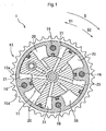
- Fig. 1 and Fig. 3 show a valve timing control apparatus 1 according to the instant embodiment.
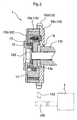
- the valve timing control apparatus 1 includes a driving-side rotary member 10 driven to rotate in synchronism with a crankshaft 100 of an internal combustion engine E and a driven-side rotary member 11 disposed coaxially with the driving-side rotary member 10 and driven to rotate in synchronism with a valve opening/closing camshaft 101 of the internal combustion engine E.
- the valve timing control apparatus 1 further includes a retard angle chamber 20 and an advance angle chamber 21 formed by the driving-side rotary member 10 and the driven-side rotary member 11, the retard angle chamber 20 being configured to move a relative rotational phase of the driven-side rotary member 11 relative to the driving-side rotary member 10 to an angle retarding direction S1, the advance angle chamber 21 being configured to move the relative rotational phase to an angle advancing direction S2, respectively, in response to feeding of a work oil respectively thereto.
- the driving-side rotary member 10 is comprised of a housing main body portion 10a disposed on the radial outer side of the driven-side rotary member 11 and a pair of housing side face portions 10b, 10c disposed on the opposed sides of the housing main body portion 10a along the axial direction of the camshaft 101 and slidable relative to the driven-side rotary member 11.
- a torsion spring 12 for urging the relative rotational phase to the angle retarding direction S1 or the angle advancing direction S2, and between the driven-side rotary member 11 and the torsion spring 12, there is provided a spring washer 14.
- the driving-side rotary member 10 is comprised of the housing main body portion 10a disposed on the radial outer side of the driven-side rotary member 11, the housing side face portion 10b disposed on the side opposite the camshaft 101 across the housing main body portion 10a and the housing side face portion 10c disposed on the side closer to the camshaft 101 than the housing main body portion 10a.
- the housing side face portion 10c is pivotally supported by the camshaft 101 via a bearing member 15. Further, the housing main body portion 10a is pivotally supported by the driven-side rotary member 11.
- the housing side face portion 10b is configured so as not to be displaced from the axis of the driven-side rotary member 11 by the pressing force provided from the torsion spring 12 described later and acting to the axial direction of the cam shaft 101.
- the housing main body portion 10a and the housing side face portions 10b, 10c are fastened together with four bolts 16, thus together constituting the driving-side rotary member 10.
- the housing side face portion 10b is set under a compressed state by the pressing force of the torsion spring 12 and the fastening forces of the bolts 16.
- the driven-side rotary member 11 does not provide direct pivotal support for the housing side face portion 10b, the axial length of the camshaft 101 can be reduced.
- the driving-side rotary member 10 can be formed of a metal such as aluminum which is light-weight and can be easily worked.
- a timing sprocket 10d is formed along the outer circumference of the housing side face portion 10c. Between this timing sprocket 10d and the crankshaft 100, there is mounted a force transmission member 102 such as a timing chain, a timing belt, etc.
- a force transmission member 102 such as a timing chain, a timing belt, etc.
- the crankshaft 100 is rotated to rotate the timing sprocket 10d via the force transmission member 102.
- the valve timing control apparatus 1 revolves in a rotational direction S.
- the driven-side rotary member 11 is mounted on the radially inner side of the housing main body portion 10a. Based on the function of work oil in the retard angle chamber 20 and the advance angle chamber 21, the relative rotational phase of the driven -side rotary member 11 relative to the driving-side rotary member 10 is varied and the driven-side rotary member 11 is rotated in synchronism with the driving-side rotary member 10. Further, the driven-side rotary member 11 is fastened to the camshaft 101 by a cam bolt 102, so that the driven-side rotary member 11 and the camshaft 101 are rotated in synchronism.
- the driven-side rotary member 11 can be formed of a metal such as aluminum which is light-weight and can be easily worked.
- the work oil to the retard angle chamber 20 and the advance angle chamber 21 is discharged from an unillustrated oil pump and fed thereto after its supply amount control by an unillustrated oil control valve.
- This oil control valve controls also discharging of the work oil from the retard angle chamber 20 and the advance angle chamber 21 to an unillustrated oil pan.
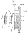
- an accommodating portion 11a for accommodating the torsion spring 12 and the spring washer 14 which will be detailed later.
- the accommodating porton11a has a bottomed circular hole shape opened on the side of the housing side face portion 10b.
- an engaged portion 11b in the form of a groove cutaway by one step lower toward the housing side face portion 10c than the bottom portion of the accommodating portion 11a. The engaged portion 11b comes into engagement with a hook portion 14b of the spring washer 14 to be described later.
- the torsion spring 12 is mounted in the accommodating portion 11a.
- This torsion spring 12 comprises a length of elongate metal wire coiled in the spiral form, with one end 12a and the other end 12b of the wire being bent to be aligned with the axial direction of the camshaft 101.
- the one end 12a thereof engages with the driven-side rotary member 11 via the hook portion 14b of the spring washer 14 to be described later and the other end 12b thereof engages with the housing side face portion 10b.
- the torsion spring 12 urges the relative rotational phase of the driven-side rotary member 11 relative to the driving-side rotary member 10 to the angle advancing direction S2.
- this torsion spring 12 is set under a compressed state compressed from its free length to a predetermined reduced length, thereby to press the housing side face portion 11 b opposite the camshaft 101 away from this camshaft 101.
- the spring washer 14 is provided in the accommodating portion 11 a, in other words, between the driven-side rotary member 11 and the torsion spring 12 along the axial direction of the camshaft 101.
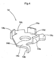
- Fig. 4 shows a perspective view of this spring washer 14.
- the spring washer 14 includes a guide portion 14a for preventing deformation to the inner radius side beyond a predetermined diameter when the torsion spring 12 urges the relative rotational phase to the angle advancing direction S2, and the hook portion 14b that engages with the driven-side rotary member 11 and extends toward the axial direction of the camshaft 101 in order to prevent the one end 12a of the torsion spring 12 from coming into direct contact with the driven-side rotary member 11.
- the spring washer 14 further includes a spring washer portion 14c for preventing direct contact between the radially extending face of the torsion spring 12 and the driven-side rotary member 11, and a cam bolt washer portion 14d for the cam bolt 102.
- the spring washer 14 can be formed of a material having a higher strength than the driven-side rotary member 11.
- the spring washer 14 can be readily formed by execution of a press work on metal in the form of a flat plate.
- valve timing control apparatus 1 As described above, with the valve timing control apparatus 1 according to the instant embodiment, even when a soft material such as aluminum is employed as the material for forming the driven-side rotary member 11, since the spring washer 14 is interposed between the driven-side rotary member 11 and the torsion spring 12, wear of the driven-side rotary member 11 in association with change in the radial dimension of the torsion spring 12 can be restricted by the spring washer portion 14c advantageously.
- the spring washer 14 there was disclosed an example thereof in which it includes the hook portion 14b that extends along the axial direction of the camshaft 101 in order to prevent the one end 12a of the torsion spring 12 from coming into direct contact with the driven-side rotary member 11.
- the spring washer 14 can include a hook portion that extends along the axial direction of the camshaft 101 in order to prevent the other end 12b of the torsion spring 12 from coming into direct contact with the housing side face portion 10b.
- the guide portion 14a of the spring washer 14 can be formed to extend further toward the housing side face portion 10b along the axial direction of the camshaft 101.
- the torsion spring 12 was configured to urge the relative rotational phase to the angle advancing direction S2.
- the torsion spring can be configured to urge the relative rotational phase to the angle retarding direction S1.
- the lock mechanism can provide even more reliable locking function.
- the present invention can be applied to a valve timing control apparatus wherein even when sliding occurs between a surface that extends along the radial direction of a spring member and at least one of a driving-side rotary member and a driven-side rotary member, wear of the at least one of the driving-side rotary member and the driven-side rotary member can be prevented.
Claims (5)
- Ventilzeitsteuerungsvorrichtung (1), mit:einem antreibende-Seite-Drehbauteil (10), das dazu angepasst ist, synchron mit einer Kurbelwelle (100) einer Brennkraftmaschine mit innerer Verbrennung gedreht zu werden;einer angetriebene-Seite-Drehbauteil (11), das koaxial mit dem antreibende-Seite-Drehbauteil (10) angeordnet ist und dazu angepasst ist, synchron mit einer Ventil-öffnenden/-schließenden Nockenwelle (101) der Brennkraftmaschine mit innerer Verbrennung gedreht zu werden; undeiner verspäteter-Winkel-Kammer (20) und einer verfrühter-Winkel-Kammer (21), die durch das antreibende-Seite-Drehbauteils (10) und das angetriebene-Seite-Drehbauteil (11) ausgebildet sind, wobei die verspäteter-Winkel-Kammer (20) dazu ausgebildet ist, eine relative Drehphase des angetriebenen-Seite-Drehbauteils (11) relativ zu dem antreibende-Seite-Drehbauteils (10) zu einer Winkel-Verspätungsrichtung zu bewegen, und die verfrühter-Winkel-Kammer (21) dazu ausgebildet ist, die relative Drehphase zu einer Winkel-Verfrühungsrichtung zu bewegen, jeweils in Reaktion auf eine Zuführung eines Arbeitsöls;bei der das antreibende-Seite-Drehbauteil (10) einen Gehäusehauptkörperbereich (10a), der auf der radialen Außenseite des angetriebene-Seite-Drehbauteils (11) angeordnet ist, und mindestens zwei Gehäuseseitenflächenbereiche (10b, 10c) aufweist, wobei jeder Gehäuseseitenflächenbereich (10b, 10c) an einem demselben entlang der Axialrichtung der Nockenwelle (101) entsprechenden Ende des Gehäusehauptkörperbereichs (10a) vorgesehen ist und relativ zu dem angetriebene Seite-Drehbauteil (11) verschiebbar ist;einem Federbauteil (12), das entlang der Axialrichtung der Nockenwelle (101) zwischen dem angetriebene-Seite-Drehbauteil (11) und dem Gehäuseseitenflächenbereich (10b) angeordnet ist, wobei das Federbauteil (12) die relative Drehphase zu der Winkel-Verfrühungsrichtung oder der Winkel-Verspätungsrichtung drückt; undeine Federscheibe (14) zwischen dem angetriebene-Seite Drehbauteil (11) und dem Federbauteil (12) angeordnet ist;bei der die Federscheibe (14) einen Hakenbereich (14b) aufweist, der sich entlang der Axialrichtung der Nockenwelle (11) erstreckt; undein Ende des Federbauteils (12) mit dem angetriebene-Seite-Drehbauteil (11) über den Hakenbereich (14b) im Eingriff ist.
- Ventilzeitsteuerungsvorrichtung nach Anspruch 1, bei der die Federscheibe (14) einen Scheibenbereich (14c) für ein Befestigungsbauteil (102) zum Befestigen der Nockenwelle (101) an dem angetriebene-Seite-Drehbauteil (11) aufweist.
- Ventilzeitsteuerungsvorrichtung nach Anspruch 1 oder 2, bei der die Federscheibe (14) einen Führungsbereich (14a) zum Beibehalten der Lage des Federbauteils (12) aufweist.
- Ventilzeitsteuerungsvorrichtung nach einem der Ansprüche 1 bis 3, bei dem das angetriebene-Seite-Drehbauteil (11) aus Aluminium ausgebildet ist und die Federscheibe (14) aus einem Material ausgebildet ist, das eine höhere Festigkeit als Aluminium aufweist.
- Ventilzeitsteuerungsvorrichtung nach einem der Ansprüche 1 bis 4, bei der das Federbauteil (12) in einen zusammengedrückten Zustand versetzt wird, in dem es von seiner freien Länge auf eine vorbestimmte Länge zusammengedrückt ist, so dass es den Gehäuseseitenflächenbereich (106) auf der Seite entgegengesetzt zu der Seite, auf der die Nockenwelle (101) vorgesehen ist, mit Druck beaufschlagt.
Applications Claiming Priority (2)
| Application Number | Priority Date | Filing Date | Title |
|---|---|---|---|
| JP2010240586A JP5505257B2 (ja) | 2010-10-27 | 2010-10-27 | 弁開閉時期制御装置 |
| PCT/JP2011/073313 WO2012056874A1 (ja) | 2010-10-27 | 2011-10-11 | 弁開閉時期制御装置 |
Publications (3)
| Publication Number | Publication Date |
|---|---|
| EP2602446A1 EP2602446A1 (de) | 2013-06-12 |
| EP2602446A4 EP2602446A4 (de) | 2013-11-20 |
| EP2602446B1 true EP2602446B1 (de) | 2014-11-26 |
Family
ID=45993601
Family Applications (1)
| Application Number | Title | Priority Date | Filing Date |
|---|---|---|---|
| EP20110836013 Not-in-force EP2602446B1 (de) | 2010-10-27 | 2011-10-11 | Vorrichtung zur steuerung einer ventilöffnungs-/schliessungszeit |
Country Status (6)
| Country | Link |
|---|---|
| US (1) | US9004028B2 (de) |
| EP (1) | EP2602446B1 (de) |
| JP (1) | JP5505257B2 (de) |
| KR (1) | KR101384064B1 (de) |
| CN (1) | CN103221647B (de) |
| WO (1) | WO2012056874A1 (de) |
Cited By (1)
| Publication number | Priority date | Publication date | Assignee | Title |
|---|---|---|---|---|
| DE102019114214A1 (de) * | 2019-05-28 | 2020-12-03 | ECO Holding 1 GmbH | Schwenkmotorversteller für eine Nockenwelle |
Families Citing this family (6)
| Publication number | Priority date | Publication date | Assignee | Title |
|---|---|---|---|---|
| JP5978080B2 (ja) * | 2012-09-19 | 2016-08-24 | 日立オートモティブシステムズ株式会社 | 内燃機関のバルブタイミング制御装置及び該バルブタイミング制御装置のコントローラ |
| CN103899375B (zh) * | 2012-12-25 | 2018-04-13 | 舍弗勒技术股份两合公司 | 一种具有中央螺栓的凸轮轴调节器 |
| EP3106632B1 (de) * | 2014-02-14 | 2019-10-30 | Aisin Seiki Kabushiki Kaisha | Vorrichtung zur steuerung der ventilöffnungs-/-schliesszeit |
| JP6225750B2 (ja) * | 2014-02-27 | 2017-11-08 | アイシン精機株式会社 | 弁開閉時期制御装置 |
| JP6222043B2 (ja) * | 2014-10-31 | 2017-11-01 | アイシン精機株式会社 | 弁開閉時期制御装置 |
| DE102015217261B3 (de) * | 2015-09-10 | 2016-12-15 | Schaeffler Technologies AG & Co. KG | Nockenwellenversteller mit einer Feder |
Family Cites Families (24)
| Publication number | Priority date | Publication date | Assignee | Title |
|---|---|---|---|---|
| DE69709231T3 (de) * | 1996-03-28 | 2009-01-08 | Aisin Seiki K.K., Kariya | Ventilzeitsteuerungsvorrichtung |
| JP3846605B2 (ja) * | 1997-10-30 | 2006-11-15 | アイシン精機株式会社 | 弁開閉時期制御装置 |
| JP4440384B2 (ja) * | 1999-09-24 | 2010-03-24 | アイシン精機株式会社 | 弁開閉時期制御装置 |
| US6276321B1 (en) | 2000-01-11 | 2001-08-21 | Delphi Technologies, Inc. | Cam phaser having a torsional bias spring to offset retarding force of camshaft friction |
| JP4465846B2 (ja) | 2000-09-27 | 2010-05-26 | アイシン精機株式会社 | 弁開閉時期制御装置 |
| JP2002161719A (ja) * | 2000-11-30 | 2002-06-07 | Denso Corp | バルブタイミング調整装置 |
| US6439184B1 (en) | 2001-01-31 | 2002-08-27 | Denso Corporation | Valve timing adjusting system of internal combustion engine |
| JP4238486B2 (ja) | 2001-03-29 | 2009-03-18 | 株式会社デンソー | バルブタイミング調整装置 |
| JP4296718B2 (ja) * | 2001-03-30 | 2009-07-15 | 株式会社デンソー | バルブタイミング調整装置 |
| JP4103580B2 (ja) * | 2002-12-24 | 2008-06-18 | アイシン精機株式会社 | 弁開閉時期制御装置 |
| JP2004300930A (ja) | 2003-03-28 | 2004-10-28 | Denso Corp | バルブタイミング調整装置 |
| JP2005002952A (ja) | 2003-06-13 | 2005-01-06 | Aisin Seiki Co Ltd | 弁開閉時期制御装置 |
| JP2005240651A (ja) | 2004-02-25 | 2005-09-08 | Aisin Seiki Co Ltd | 弁開閉時期制御装置 |
| EP1754864B9 (de) * | 2004-06-22 | 2012-10-17 | Aisin Seiki Kabushiki Kaisha | Vorrichtung zur zeitsteuerung des öffnens/schliessens eines ventils |
| JP4110479B2 (ja) | 2004-09-28 | 2008-07-02 | アイシン精機株式会社 | 弁開閉時期制御装置 |
| JP4247624B2 (ja) | 2004-12-28 | 2009-04-02 | 株式会社デンソー | バルブタイミング調整装置 |
| JP2009074424A (ja) * | 2007-09-20 | 2009-04-09 | Denso Corp | バルブタイミング調整装置 |
| JP2009185766A (ja) * | 2008-02-08 | 2009-08-20 | Denso Corp | バルブタイミング調整装置 |
| US7958857B2 (en) * | 2008-09-17 | 2011-06-14 | Delphi Technologies, Inc. | Cam phaser helical bias spring having a square end for retention |
| JP5516938B2 (ja) * | 2009-02-26 | 2014-06-11 | アイシン精機株式会社 | 弁開閉時期制御装置 |
| JP5321911B2 (ja) * | 2009-09-25 | 2013-10-23 | アイシン精機株式会社 | 弁開閉時期制御装置 |
| JP5357137B2 (ja) * | 2010-12-24 | 2013-12-04 | 日立オートモティブシステムズ株式会社 | 内燃機関のバルブタイミング制御装置 |
| US9103239B2 (en) * | 2011-12-27 | 2015-08-11 | Aisin Seiki Kabushiki Kaisha | Valve opening-closing timing control device and method for attaching front member thereof |
| JP5994297B2 (ja) * | 2012-03-08 | 2016-09-21 | アイシン精機株式会社 | 弁開閉時期制御装置 |
-
2010
- 2010-10-27 JP JP2010240586A patent/JP5505257B2/ja active Active
-
2011
- 2011-10-11 WO PCT/JP2011/073313 patent/WO2012056874A1/ja active Application Filing
- 2011-10-11 EP EP20110836013 patent/EP2602446B1/de not_active Not-in-force
- 2011-10-11 CN CN201180043093.0A patent/CN103221647B/zh not_active Expired - Fee Related
- 2011-10-11 KR KR1020137005665A patent/KR101384064B1/ko active IP Right Grant
- 2011-10-11 US US13/821,394 patent/US9004028B2/en not_active Expired - Fee Related
Cited By (1)
| Publication number | Priority date | Publication date | Assignee | Title |
|---|---|---|---|---|
| DE102019114214A1 (de) * | 2019-05-28 | 2020-12-03 | ECO Holding 1 GmbH | Schwenkmotorversteller für eine Nockenwelle |
Also Published As
| Publication number | Publication date |
|---|---|
| JP5505257B2 (ja) | 2014-05-28 |
| KR101384064B1 (ko) | 2014-04-09 |
| US20130167787A1 (en) | 2013-07-04 |
| CN103221647A (zh) | 2013-07-24 |
| KR20130054360A (ko) | 2013-05-24 |
| EP2602446A4 (de) | 2013-11-20 |
| EP2602446A1 (de) | 2013-06-12 |
| US9004028B2 (en) | 2015-04-14 |
| WO2012056874A1 (ja) | 2012-05-03 |
| CN103221647B (zh) | 2015-09-23 |
| JP2012092739A (ja) | 2012-05-17 |
Similar Documents
| Publication | Publication Date | Title |
|---|---|---|
| EP2602446B1 (de) | Vorrichtung zur steuerung einer ventilöffnungs-/schliessungszeit | |
| JP4161277B2 (ja) | 弁開閉時期制御装置 | |
| US7444970B2 (en) | Valve timing controlling apparatus | |
| EP2530259B1 (de) | Variable ventilsteuerung für einen verbrennungsmotor | |
| JP4296718B2 (ja) | バルブタイミング調整装置 | |
| JP5987868B2 (ja) | バルブタイミング調整装置 | |
| US20120174884A1 (en) | Variable Valve Timing Control Apparatus of Internal Combustion Engine | |
| US20090199801A1 (en) | Valve timing adjusting apparatus | |
| EP1217176B1 (de) | Ventilsteuerungsvorrichtung | |
| EP2894304B1 (de) | Ventilzeitsteuerung | |
| US20020040697A1 (en) | Valve timing adjusting device having stopper piston | |
| JP6394222B2 (ja) | 弁開閉時期制御装置 | |
| CN106939806B (zh) | 阀开闭定时控制装置 | |
| JP5920632B2 (ja) | バルブタイミング調整装置 | |
| WO2020255390A1 (ja) | バルブタイミング調整装置 | |
| CN111279055B (zh) | 气门正时调整装置 | |
| JP6436848B2 (ja) | バルブタイミング調整装置 | |
| JP3882907B2 (ja) | 高圧サプライポンプ | |
| JP2002054408A (ja) | 内燃機関のバルブタイミング制御装置 | |
| US7500455B2 (en) | Valve timing control apparatus | |
| US20050045128A1 (en) | Camshaft incorporating variable camshaft timing phaser rotor | |
| CN117967421A (zh) | 扭矩限制扭转万向节 | |
| CN109469525A (zh) | 具有绕轨道运转偏心齿轮的电动相位器 | |
| JP2011069242A (ja) | 弁開閉時期制御装置 |
Legal Events
| Date | Code | Title | Description |
|---|---|---|---|
| PUAI | Public reference made under article 153(3) epc to a published international application that has entered the european phase |
Free format text: ORIGINAL CODE: 0009012 |
|
| 17P | Request for examination filed |
Effective date: 20130306 |
|
| AK | Designated contracting states |
Kind code of ref document: A1 Designated state(s): AL AT BE BG CH CY CZ DE DK EE ES FI FR GB GR HR HU IE IS IT LI LT LU LV MC MK MT NL NO PL PT RO RS SE SI SK SM TR |
|
| A4 | Supplementary search report drawn up and despatched |
Effective date: 20131023 |
|
| RIC1 | Information provided on ipc code assigned before grant |
Ipc: F01L 1/344 20060101AFI20131017BHEP |
|
| DAX | Request for extension of the european patent (deleted) | ||
| REG | Reference to a national code |
Ref country code: DE Ref legal event code: R079 Ref document number: 602011011815 Country of ref document: DE Free format text: PREVIOUS MAIN CLASS: F01L0001356000 Ipc: F01L0001344000 |
|
| GRAP | Despatch of communication of intention to grant a patent |
Free format text: ORIGINAL CODE: EPIDOSNIGR1 |
|
| RIC1 | Information provided on ipc code assigned before grant |
Ipc: F01L 1/344 20060101AFI20140530BHEP |
|
| INTG | Intention to grant announced |
Effective date: 20140701 |
|
| GRAS | Grant fee paid |
Free format text: ORIGINAL CODE: EPIDOSNIGR3 |
|
| GRAA | (expected) grant |
Free format text: ORIGINAL CODE: 0009210 |
|
| AK | Designated contracting states |
Kind code of ref document: B1 Designated state(s): AL AT BE BG CH CY CZ DE DK EE ES FI FR GB GR HR HU IE IS IT LI LT LU LV MC MK MT NL NO PL PT RO RS SE SI SK SM TR |
|
| REG | Reference to a national code |
Ref country code: GB Ref legal event code: FG4D |
|
| REG | Reference to a national code |
Ref country code: CH Ref legal event code: EP |
|
| REG | Reference to a national code |
Ref country code: AT Ref legal event code: REF Ref document number: 698345 Country of ref document: AT Kind code of ref document: T Effective date: 20141215 |
|
| REG | Reference to a national code |
Ref country code: IE Ref legal event code: FG4D |
|
| REG | Reference to a national code |
Ref country code: DE Ref legal event code: R096 Ref document number: 602011011815 Country of ref document: DE Effective date: 20150108 |
|
| REG | Reference to a national code |
Ref country code: NL Ref legal event code: VDEP Effective date: 20141126 |
|
| REG | Reference to a national code |
Ref country code: AT Ref legal event code: MK05 Ref document number: 698345 Country of ref document: AT Kind code of ref document: T Effective date: 20141126 |
|
| REG | Reference to a national code |
Ref country code: LT Ref legal event code: MG4D |
|
| PG25 | Lapsed in a contracting state [announced via postgrant information from national office to epo] |
Ref country code: PT Free format text: LAPSE BECAUSE OF FAILURE TO SUBMIT A TRANSLATION OF THE DESCRIPTION OR TO PAY THE FEE WITHIN THE PRESCRIBED TIME-LIMIT Effective date: 20150326 Ref country code: NL Free format text: LAPSE BECAUSE OF FAILURE TO SUBMIT A TRANSLATION OF THE DESCRIPTION OR TO PAY THE FEE WITHIN THE PRESCRIBED TIME-LIMIT Effective date: 20141126 Ref country code: NO Free format text: LAPSE BECAUSE OF FAILURE TO SUBMIT A TRANSLATION OF THE DESCRIPTION OR TO PAY THE FEE WITHIN THE PRESCRIBED TIME-LIMIT Effective date: 20150226 Ref country code: LT Free format text: LAPSE BECAUSE OF FAILURE TO SUBMIT A TRANSLATION OF THE DESCRIPTION OR TO PAY THE FEE WITHIN THE PRESCRIBED TIME-LIMIT Effective date: 20141126 Ref country code: ES Free format text: LAPSE BECAUSE OF FAILURE TO SUBMIT A TRANSLATION OF THE DESCRIPTION OR TO PAY THE FEE WITHIN THE PRESCRIBED TIME-LIMIT Effective date: 20141126 Ref country code: IS Free format text: LAPSE BECAUSE OF FAILURE TO SUBMIT A TRANSLATION OF THE DESCRIPTION OR TO PAY THE FEE WITHIN THE PRESCRIBED TIME-LIMIT Effective date: 20150326 Ref country code: FI Free format text: LAPSE BECAUSE OF FAILURE TO SUBMIT A TRANSLATION OF THE DESCRIPTION OR TO PAY THE FEE WITHIN THE PRESCRIBED TIME-LIMIT Effective date: 20141126 |
|
| PG25 | Lapsed in a contracting state [announced via postgrant information from national office to epo] |
Ref country code: LV Free format text: LAPSE BECAUSE OF FAILURE TO SUBMIT A TRANSLATION OF THE DESCRIPTION OR TO PAY THE FEE WITHIN THE PRESCRIBED TIME-LIMIT Effective date: 20141126 Ref country code: CY Free format text: LAPSE BECAUSE OF FAILURE TO SUBMIT A TRANSLATION OF THE DESCRIPTION OR TO PAY THE FEE WITHIN THE PRESCRIBED TIME-LIMIT Effective date: 20141126 Ref country code: SE Free format text: LAPSE BECAUSE OF FAILURE TO SUBMIT A TRANSLATION OF THE DESCRIPTION OR TO PAY THE FEE WITHIN THE PRESCRIBED TIME-LIMIT Effective date: 20141126 Ref country code: HR Free format text: LAPSE BECAUSE OF FAILURE TO SUBMIT A TRANSLATION OF THE DESCRIPTION OR TO PAY THE FEE WITHIN THE PRESCRIBED TIME-LIMIT Effective date: 20141126 Ref country code: RS Free format text: LAPSE BECAUSE OF FAILURE TO SUBMIT A TRANSLATION OF THE DESCRIPTION OR TO PAY THE FEE WITHIN THE PRESCRIBED TIME-LIMIT Effective date: 20141126 Ref country code: GR Free format text: LAPSE BECAUSE OF FAILURE TO SUBMIT A TRANSLATION OF THE DESCRIPTION OR TO PAY THE FEE WITHIN THE PRESCRIBED TIME-LIMIT Effective date: 20150227 Ref country code: AT Free format text: LAPSE BECAUSE OF FAILURE TO SUBMIT A TRANSLATION OF THE DESCRIPTION OR TO PAY THE FEE WITHIN THE PRESCRIBED TIME-LIMIT Effective date: 20141126 |
|
| PG25 | Lapsed in a contracting state [announced via postgrant information from national office to epo] |
Ref country code: RO Free format text: LAPSE BECAUSE OF FAILURE TO SUBMIT A TRANSLATION OF THE DESCRIPTION OR TO PAY THE FEE WITHIN THE PRESCRIBED TIME-LIMIT Effective date: 20141126 Ref country code: SK Free format text: LAPSE BECAUSE OF FAILURE TO SUBMIT A TRANSLATION OF THE DESCRIPTION OR TO PAY THE FEE WITHIN THE PRESCRIBED TIME-LIMIT Effective date: 20141126 Ref country code: CZ Free format text: LAPSE BECAUSE OF FAILURE TO SUBMIT A TRANSLATION OF THE DESCRIPTION OR TO PAY THE FEE WITHIN THE PRESCRIBED TIME-LIMIT Effective date: 20141126 Ref country code: DK Free format text: LAPSE BECAUSE OF FAILURE TO SUBMIT A TRANSLATION OF THE DESCRIPTION OR TO PAY THE FEE WITHIN THE PRESCRIBED TIME-LIMIT Effective date: 20141126 Ref country code: EE Free format text: LAPSE BECAUSE OF FAILURE TO SUBMIT A TRANSLATION OF THE DESCRIPTION OR TO PAY THE FEE WITHIN THE PRESCRIBED TIME-LIMIT Effective date: 20141126 |
|
| REG | Reference to a national code |
Ref country code: DE Ref legal event code: R097 Ref document number: 602011011815 Country of ref document: DE |
|
| PG25 | Lapsed in a contracting state [announced via postgrant information from national office to epo] |
Ref country code: PL Free format text: LAPSE BECAUSE OF FAILURE TO SUBMIT A TRANSLATION OF THE DESCRIPTION OR TO PAY THE FEE WITHIN THE PRESCRIBED TIME-LIMIT Effective date: 20141126 |
|
| PLBE | No opposition filed within time limit |
Free format text: ORIGINAL CODE: 0009261 |
|
| STAA | Information on the status of an ep patent application or granted ep patent |
Free format text: STATUS: NO OPPOSITION FILED WITHIN TIME LIMIT |
|
| 26N | No opposition filed |
Effective date: 20150827 |
|
| PG25 | Lapsed in a contracting state [announced via postgrant information from national office to epo] |
Ref country code: IT Free format text: LAPSE BECAUSE OF FAILURE TO SUBMIT A TRANSLATION OF THE DESCRIPTION OR TO PAY THE FEE WITHIN THE PRESCRIBED TIME-LIMIT Effective date: 20141126 |
|
| PG25 | Lapsed in a contracting state [announced via postgrant information from national office to epo] |
Ref country code: SI Free format text: LAPSE BECAUSE OF FAILURE TO SUBMIT A TRANSLATION OF THE DESCRIPTION OR TO PAY THE FEE WITHIN THE PRESCRIBED TIME-LIMIT Effective date: 20141126 |
|
| PG25 | Lapsed in a contracting state [announced via postgrant information from national office to epo] |
Ref country code: LU Free format text: LAPSE BECAUSE OF FAILURE TO SUBMIT A TRANSLATION OF THE DESCRIPTION OR TO PAY THE FEE WITHIN THE PRESCRIBED TIME-LIMIT Effective date: 20151011 |
|
| REG | Reference to a national code |
Ref country code: CH Ref legal event code: PL |
|
| GBPC | Gb: european patent ceased through non-payment of renewal fee |
Effective date: 20151011 |
|
| PG25 | Lapsed in a contracting state [announced via postgrant information from national office to epo] |
Ref country code: MC Free format text: LAPSE BECAUSE OF FAILURE TO SUBMIT A TRANSLATION OF THE DESCRIPTION OR TO PAY THE FEE WITHIN THE PRESCRIBED TIME-LIMIT Effective date: 20141126 |
|
| REG | Reference to a national code |
Ref country code: IE Ref legal event code: MM4A |
|
| PG25 | Lapsed in a contracting state [announced via postgrant information from national office to epo] |
Ref country code: LI Free format text: LAPSE BECAUSE OF NON-PAYMENT OF DUE FEES Effective date: 20151031 Ref country code: GB Free format text: LAPSE BECAUSE OF NON-PAYMENT OF DUE FEES Effective date: 20151011 Ref country code: CH Free format text: LAPSE BECAUSE OF NON-PAYMENT OF DUE FEES Effective date: 20151031 |
|
| REG | Reference to a national code |
Ref country code: FR Ref legal event code: PLFP Year of fee payment: 6 |
|
| PG25 | Lapsed in a contracting state [announced via postgrant information from national office to epo] |
Ref country code: IE Free format text: LAPSE BECAUSE OF NON-PAYMENT OF DUE FEES Effective date: 20151011 |
|
| PG25 | Lapsed in a contracting state [announced via postgrant information from national office to epo] |
Ref country code: BG Free format text: LAPSE BECAUSE OF FAILURE TO SUBMIT A TRANSLATION OF THE DESCRIPTION OR TO PAY THE FEE WITHIN THE PRESCRIBED TIME-LIMIT Effective date: 20141126 Ref country code: HU Free format text: LAPSE BECAUSE OF FAILURE TO SUBMIT A TRANSLATION OF THE DESCRIPTION OR TO PAY THE FEE WITHIN THE PRESCRIBED TIME-LIMIT; INVALID AB INITIO Effective date: 20111011 Ref country code: SM Free format text: LAPSE BECAUSE OF FAILURE TO SUBMIT A TRANSLATION OF THE DESCRIPTION OR TO PAY THE FEE WITHIN THE PRESCRIBED TIME-LIMIT Effective date: 20141126 |
|
| PG25 | Lapsed in a contracting state [announced via postgrant information from national office to epo] |
Ref country code: MT Free format text: LAPSE BECAUSE OF FAILURE TO SUBMIT A TRANSLATION OF THE DESCRIPTION OR TO PAY THE FEE WITHIN THE PRESCRIBED TIME-LIMIT Effective date: 20141126 |
|
| REG | Reference to a national code |
Ref country code: FR Ref legal event code: PLFP Year of fee payment: 7 |
|
| PG25 | Lapsed in a contracting state [announced via postgrant information from national office to epo] |
Ref country code: BE Free format text: LAPSE BECAUSE OF FAILURE TO SUBMIT A TRANSLATION OF THE DESCRIPTION OR TO PAY THE FEE WITHIN THE PRESCRIBED TIME-LIMIT Effective date: 20141126 |
|
| PG25 | Lapsed in a contracting state [announced via postgrant information from national office to epo] |
Ref country code: TR Free format text: LAPSE BECAUSE OF FAILURE TO SUBMIT A TRANSLATION OF THE DESCRIPTION OR TO PAY THE FEE WITHIN THE PRESCRIBED TIME-LIMIT Effective date: 20141126 Ref country code: MK Free format text: LAPSE BECAUSE OF FAILURE TO SUBMIT A TRANSLATION OF THE DESCRIPTION OR TO PAY THE FEE WITHIN THE PRESCRIBED TIME-LIMIT Effective date: 20141126 |
|
| REG | Reference to a national code |
Ref country code: FR Ref legal event code: PLFP Year of fee payment: 8 |
|
| PG25 | Lapsed in a contracting state [announced via postgrant information from national office to epo] |
Ref country code: AL Free format text: LAPSE BECAUSE OF FAILURE TO SUBMIT A TRANSLATION OF THE DESCRIPTION OR TO PAY THE FEE WITHIN THE PRESCRIBED TIME-LIMIT Effective date: 20141126 |
|
| PGFP | Annual fee paid to national office [announced via postgrant information from national office to epo] |
Ref country code: FR Payment date: 20190913 Year of fee payment: 9 |
|
| PGFP | Annual fee paid to national office [announced via postgrant information from national office to epo] |
Ref country code: DE Payment date: 20191001 Year of fee payment: 9 |
|
| REG | Reference to a national code |
Ref country code: DE Ref legal event code: R119 Ref document number: 602011011815 Country of ref document: DE |
|
| PG25 | Lapsed in a contracting state [announced via postgrant information from national office to epo] |
Ref country code: DE Free format text: LAPSE BECAUSE OF NON-PAYMENT OF DUE FEES Effective date: 20210501 Ref country code: FR Free format text: LAPSE BECAUSE OF NON-PAYMENT OF DUE FEES Effective date: 20201031 |