EP2584107A1 - Sanitary assembly - Google Patents
Sanitary assembly Download PDFInfo
- Publication number
- EP2584107A1 EP2584107A1 EP13151731.0A EP13151731A EP2584107A1 EP 2584107 A1 EP2584107 A1 EP 2584107A1 EP 13151731 A EP13151731 A EP 13151731A EP 2584107 A1 EP2584107 A1 EP 2584107A1
- Authority
- EP
- European Patent Office
- Prior art keywords
- wall
- tub body
- prewall
- sanitary
- arrangement according
- Prior art date
- Legal status (The legal status is an assumption and is not a legal conclusion. Google has not performed a legal analysis and makes no representation as to the accuracy of the status listed.)
- Granted
Links
Images


Classifications
-
- E—FIXED CONSTRUCTIONS
- E03—WATER SUPPLY; SEWERAGE
- E03F—SEWERS; CESSPOOLS
- E03F5/00—Sewerage structures
- E03F5/04—Gullies inlets, road sinks, floor drains with or without odour seals or sediment traps
- E03F5/0407—Floor drains for indoor use
- E03F5/0408—Floor drains for indoor use specially adapted for showers
-
- A—HUMAN NECESSITIES
- A47—FURNITURE; DOMESTIC ARTICLES OR APPLIANCES; COFFEE MILLS; SPICE MILLS; SUCTION CLEANERS IN GENERAL
- A47K—SANITARY EQUIPMENT NOT OTHERWISE PROVIDED FOR; TOILET ACCESSORIES
- A47K3/00—Baths; Douches; Appurtenances therefor
- A47K3/28—Showers or bathing douches
- A47K3/40—Pans or trays
-
- E—FIXED CONSTRUCTIONS
- E03—WATER SUPPLY; SEWERAGE
- E03C—DOMESTIC PLUMBING INSTALLATIONS FOR FRESH WATER OR WASTE WATER; SINKS
- E03C1/00—Domestic plumbing installations for fresh water or waste water; Sinks
- E03C1/12—Plumbing installations for waste water; Basins or fountains connected thereto; Sinks
- E03C1/14—Wash-basins connected to the waste-pipe
-
- E—FIXED CONSTRUCTIONS
- E03—WATER SUPPLY; SEWERAGE
- E03C—DOMESTIC PLUMBING INSTALLATIONS FOR FRESH WATER OR WASTE WATER; SINKS
- E03C1/00—Domestic plumbing installations for fresh water or waste water; Sinks
- E03C1/12—Plumbing installations for waste water; Basins or fountains connected thereto; Sinks
- E03C1/20—Connecting baths or bidets to the wastepipe
Definitions
- the invention relates to a sanitary arrangement with a wall having a cavity or pretext, a one-piece bath body and a drain device, which is arranged in the region of the wall or pretext and which is connected to the tub body.
- the tub body forms a shower tray or sink.
- the drainage area is visible.
- the tub body of the shower tray on a visible drain opening to the underside of a drain device, for example in the form of a siphon is connected. From practice shower trays with drain holes in different shapes, location and size are known.
- From the EP 2 101 004 A2 is an inserted into the wall washbasin with the features of the preamble of claim 1 known.
- a fixed in the wall rear shell of the sink is hinged to a fold-out front shell of the sink. When the front shell is folded out, it serves as a liquid-collecting surface. The water drain is connected to the rear shell. Due to the fold-out configuration of the front shell, it is not readily possible to arrange a cover, cladding or the like above this shell, because this would then prevent collapse.
- A1 is a sanitary arrangement with the features described above known.
- a floor-level shower with a cavity having wall or pretext in which a shower channel assembly is used for wall installation.
- a formed from individual tiles tub body closes with its edge to the shower channel assembly for wall mounting. Both below the individual tiles and at the connection to the shower channel arrangement is a to carry out complex sealing.
- a subsequent change or reconstruction of the sanitary order is not readily possible. If the seal is insufficient, there is a risk that water will enter the floor and / or the wall.
- the invention has for its object to provide a sanitary arrangement that can be easily mounted and in which the risk of uncontrolled leaking water is reduced.
- the object of the invention and solution of the problem is a sanitary arrangement according to claim 1.
- the tub body is made as a one-piece, contiguous body of a waterproof material. With this tub body, the water is passed without further joints or joints to the drain opening, which is formed within the base of the tub body. All water can thus leave the tub body only through the drain opening and the attached drainage device.
- the one-piece, contiguous shape of the tub body can be used.
- the tub body usually extends above the drainage device in the wall or preamble, in which case the drainage device is connected from below to the discharge opening formed in the tub body. In principle, however, it is also conceivable to connect the drainage device laterally to a step or edge of the bath body. Even with such a configuration is crucial that the tub body is formed as a continuous element with internal drainage opening.
- the tub body has a utility area outside the wall for collecting water, which impinges on the tub body from above.
- the useful area In a shower tray, the useful area directly forms the tread for a user.
- the utility area also serves to catch the water flowing down from a shower head or a faucet and drain it to the drain.
- the useful area of the bath body arranged outside the wall or prewall in the sanitary arrangement according to the invention is significantly larger than the area which extends into the wall or wall. While the working area must collect all the water flowing down and also serves as a stepping surface in a shower, the section of the bath body extending into the wall is provided essentially only for a concealed discharge of the water.
- the tub body has a raised edge opposite the region around the drain opening on a side extending within the wall or prewall and on at least part of the sides extending away from the wall or prewall.
- the tub body can thus be made similar to a known floor-level shower tray made of sanitary acrylic or steel enamel, but according to the invention, the entire drainage area is hidden in the wall or pretext.
- the tub body on its wall or pretext opposite side can just run out, so that the tub body completely barrier-free, z. B. also with a wheelchair, can be entered.
- body can be provided with a low or a high level. At least in the latter case is in the Accessibility is no longer given, but at the same time the risk of overflow is reduced even with a lower drainage performance.
- a planar section is provided at the edge, with a substantially S-shaped course resulting therefrom in the direction of the center of the tub body.
- the curvatures can vary within a very wide range.
- an S-shape with small radii results in a clearly perceptible stage with a steep trough portion in the S-shaped area.
- a smooth, smooth transition from the flat section towards the center of the tub body may also be provided.
- the S-shaped region may, for example, extend directly to a center line of the tub body, so that the two S-shaped regions merge into one another in a cross section.
- any shapes between a very steep and a very shallow S-shape are conceivable. If at the wall or prewall opposite side of the tub body does not leak, there may also be provided a paragraph or a step, in particular with an S-shape. Between the two extending away from the wall or pretext sides may also be provided an increase in the middle, so that there is a W-shape in cross section. From slightly curved shapes to a design with clearly defined grooves in the edge area, different contours are possible. Finally, asymmetric shapes with a laterally different waste, a groove on only one side or the like are possible. However, the entire tub body is usually shaped so that it at least slightly drops in the direction of the drain opening in order to remove all the water can. The peripheral edge of the tub body is expediently in a plane.
- a pretext a subsequently added to a wall wall section, which can extend over the entire height as well as only over part of the height of the wall behind it. If the pretext only extends over a part of the height, a shoulder can be formed as the upper conclusion of the pretext which, for example, can be used as a storage surface.
- wall and pretext is not strictly within the scope of the invention.
- the tub body can consist of plastic, glass, ceramic, a composite material or preferably of steel enamel.
- the plastic can be formed on thermoset as well as thermoplastic base. While thermosetting plastics are poured into the trough shape, in thermoplastic materials, for example, an injection molding of the molten plastic or a deep drawing from a plate takes place.
- the plastic may also contain fillers or reinforcing substances, for example fibers or mineral particles.
- suitable materials also fall foamed plastics, which have sufficient carrying capacity as a tub body. In principle, several layers and layers can be pressed, laminated or glued together. The top of the tub body forms in a shower tray by a user directly to be entered effective area of the tub body.
- the drain opening is a slight gradation of the bottom of the tub body down appropriate to connect a drain substantially flush.
- the gradation is significantly lower than in conventional drains on conventional shower trays, in which a drain fitting is connected to the underside, which is visible to a user or hidden by a separate lid. The necessary for the installation of the sanitary order depth can thus be minimized within the scope of the invention.
- the cavity formed in the wall or pretext is expediently designed such that condensation and spray water can not penetrate into the wall or pretext or a floor below the tub body.
- a hood made of waterproof material is arranged in the cavity of the wall or pretext above the tub body and the drainage device.
- the hood protects the wall from moisture and is preferably designed and arranged such that it completely covers the material of the wall or prewall laterally and above the cavity.
- the hood can be made of plastic, stainless steel or coated steel, in particular steel enamel or other waterproof and water-resistant materials.
- the hood of the same material as the tub body, so in particular sanitary acrylic or steel enamel exist. Furthermore, a tight connection of the hood to the tub body is provided, for which purpose, for example, a sealing material can be used.
- the cavity and optionally provided hood need not extend over the entire width of the tub body.
- the wall or pretext may have a cover above the tub body, wherein at least one slot is at least partially formed between the cover and the tub body. Through the slot, the water can flow in the direction of the drain opening and the drain device.
- the slot may extend over the entire width or only over a part of the width of the preferably rectangular pan body.
- the cover can be folded away laterally or upwards and / or removed.
- hinges can be provided with a scissor mechanism, for example.
- the cover which is pivotable about a horizontal axis, for example, held by the described, an opening assisting means in the open position or snaps there. In both cases, the cover does not need to be held by a user in the open position while cleaning and / or assembly work is being done in the cavity.
- the cover is at least slightly shorter than the entire width of the tub body along the wall, in order to avoid blocking when using Duschabtrennungen.
- the cover can be made optically free, wherein in particular laterally and / or according to the course of the tub body below the cover individually adapted spacers can be used.
- the wall or pretext can basically other technical facilities or controls and supply lines of a water supply to get integrated. Such integration can take place in the construction of the sanitary order. Basically, in a wall or pretext and boxes are attached, which can be opened later, so that arranged therein devices remain accessible. In the context of the invention, however, there is just the advantage that by providing the cavity anyway a free space is available, which can also be used for the arrangement of technical facilities that can not be integrated or otherwise not readily in a conventional shower tray , These devices can be provided for example for ventilation and / or heating and / or sound and / or scenting and / or Bewebung or vaporization of the sanitary order. In principle, both comfort functions and practical functions can be realized. It is conceivable inter alia within the cavity, so in particular within the optionally provided hood, facilities for playing music, lighting, facilities for the introduction of steam or fog, use a scent generator or the like, whereby the utility of the sanitary arrangement is significantly increased.
- a ventilation in particular a circulation of air or even a supply or removal of air is possible.
- an attached pipe ventilator may be provided for drying the shower area.
- Such ventilation can in principle also be combined with heating.
- devices for automatic cleaning, disinfecting or the like can be arranged in the free space. This results in the advantage that the free space according to a preferred embodiment of the invention described above is both accessible, in particular sealed by a cover, as well as with respect to the wall or the front wall. Due to the accessibility, the technical equipment is checked, cleaned, maintained, replaced or supplemented. Optionally, also resources, such as equipment for aeration, cleaning or disinfection, can be easily refilled.
- the sanitary arrangement is provided at a distance to an underlying floor surface as a washbasin, wherein the bath body extends into the wall or pretext.
- the tub body is to be sealed at its edge to the adjacent wall or the floor to a sufficient extent.
- a particularly good protection against the escape of moisture can be achieved in that the profile pieces described on their outer side in the assembled state have an upwardly open channel, in which an edge of the tub body is inserted.
- the tub body can be bent starting from a flat portion at its edge C-shaped downwards. This C-shaped bend can then be inserted into the upwardly open channel.
- the provided according to a preferred embodiment of the invention hood can be inserted into the upwardly open channel. Even if water drips on the hood or the tub body despite a corresponding seal, this is collected in the gutter. It may be provided to connect the channel also to a drain.
- the tub body has a rectangular, for example, square shape in the simplest embodiment.
- other shapes are possible within the scope of the invention.
- bends as well as uneven Shapes may be provided on the circumference of the tub body.
- the tub body does not have to extend with a complete page in the wall or pretext, even if this is preferred.
- a lateral bulge is provided on the side of the tub body arranged in the region of the wall or preamble, this bulge extending into the wall.
- the cover is made narrower than the entire width of the tub body on the wall or pretext.
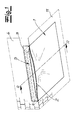
- the Fig. 1 shows a sanitary arrangement in the form of a floor-level shower, which has a tub body 1.
- the tub body 1 according to a preferred embodiment of the invention of sanitary acrylic or steel enamel, wherein the top of the tub body directly from a user to entering area forms.
- the tub body 1 is covered in the context of the invention with other material, such as tiles. It can also be seen that the tub body 1 has a rectangular base and drops towards the middle.
- tub body 1 extends into the wall or pretext 4, wherein the tub body 1 in the hidden area for a user has a drain opening 5. Since the drainage opening 5 is not visible to a user, this can also have an elongated shape and does not need to be covered.
- a one-piece, contiguous bath body 1 which has a drain opening 5 only within its base area.
- the tub body 1 is shaped so that water is always guided in the direction of the drain opening 5 and can leave the tub body only there.
- it must be ensured that not the entire tub, that is, the entire tub body 1, overflows.
- a comparatively large drain opening 5 can be provided without any visual impairment, just in the context of the inventive design, a very high drainage capacity is possible.
- Fig. 2 The details of the sanitary arrangement according to the invention result from the in Fig. 2 shown section along the line AA, with a middle portion of this section is not shown for reasons of clarity.
- the Fig. 2 is to be understood that the tub body, starting from its wall or the front wall 4 opposite side uniformly along the section line AA to the drain opening 5 drops.
- a cavity 6 is formed within the wall mounted on a behind wall surface pretext 4. Furthermore, in the hidden area below the cavity 6, a draining device 7, which is indicated only schematically, is connected from below to the drain opening 5 formed in the tub body 1.
- the drain device usually has a siphon not shown in detail. Suitable drain devices 7 are known from practice.
- a hood 8 is arranged made of waterproof material.
- the hood 8 can be made of the same material as the tub body 1, so in particular steel enamel or sanitary acrylic. In addition, however, stainless steel or another waterproof and water-resistant material is suitable.
- the already in the Fig. 1 to be recognized cover 3 is in accordance with Fig. 2 attached by hinges 9 to the hood 8.
- the hinges 9 have a scissor mechanism, which keeps the cover 3 pivoted about a horizontal pivot axis in the open position.
- means may be provided in the form of springs or pressure piston, which support a lifting of the cover 3.
- the tub body 1 runs on its side opposite the front wall 4 at ground level into an adjacent bottom surface 11.
- the remaining edges of the tub body 1 have a different degree of curved S-shape. It is thereby achieved that the tub body 1 has a raised edge opposite the region of the drain opening 5 on its side running within the wall or wall 4 and on its side extending away from the wall or wall 4.
- At the edge of a flat portion 10 is provided, resulting from the flat portion 10 in the direction of the center of the tub body 1 is an essential S-shaped curve.
- the S-shape is steep, while at the extending away from the wall or pretext pages for optical reasons, a flat course is provided.
- a free space is provided in the region of the tub body 1 in a particularly advantageous manner, which can be used to arrange further technical equipment E, which is purely schematic in the Fig. 2 are indicated.
- the technical equipment E can be provided for example for sound, ventilation, heating, scenting, Bewebung or cleaning.
- the measures mentioned can be provided individually or in any combination.
- a recess 12 is formed in the bottom surface 11 corresponding to the shape of the tub body 1.
- a shower tray support 13 is arranged, which carries the tub body 1.
- the shower tray support 13 has according to the preferred embodiment illustrated feet 14 and a frame of profile pieces 15.
- the profile pieces 15 in a cross section a support portion 16 for the tub body 1 and for the attachment of the feet 14 a C-shaped groove portion, wherein the feet 14 are fastened via head elements 17 to the profile pieces 15 and wherein the head elements 17 are each arranged laterally on an associated profile piece 15 and with a holding extension in a slot of engage laterally open groove area.
- the profile pieces 15 have an upwardly open channel 18 on their outer side in the mounted state.
- a shower tray support 13 in particular a described shower tray support 13 with feet 14 and profile pieces 15 is not only a simple and accurate installation possible. Rather, the tub body 1 can also be easily replaced.
- connection of the hood 8 to the tub body 1 and the profile piece 15 is exactly like the connection of the tub body 1 and the profile pieces 15 to the adjacent floor or the wall with a suitable, usually elastic sealing material 20. It is alternatively possible, the hood 8 with the shower tray support 13 to weld.
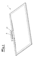
- the Fig. 3 shows a further embodiment with two sanitary arrangements according to the present invention.
- the first in the Fig. 3 shown sanitary arrangement is as previously described designed as a floor-level shower.
- a clearly formed edge can also be provided. This is achieved by providing a steeper S-shape at these edges.
- the tub body 1 made of steel enamel arise, however, with respect to the bends and radii certain restrictions by the Blechumform processes.
- the second in the Fig. 3 shown sanitary arrangement is designed as a sink.
- a tub body 1 is provided which extends into the wall or pretext 4 inside.
- the tub body 1 is not supported down, but is completely fixed with a suitable attitude within the wall or pretext 4.
- the Fig. 4 shows an alternative embodiment of the tub body 1, wherein in the region of the drain opening 5 of the tub body has a lateral bulge 21 which extends in the mounted state in the wall or pretext 4 inside.
Abstract
Description
Die Erfindung betrifft eine Sanitäranordnung mit einer einen Hohlraum aufweisenden Wand oder Vorwand, einem einstückigen Wannenkörper und einer Ablaufeinrichtung, die im Bereich der Wand oder Vorwand angeordnet und die an den Wannenkörper angeschlossen ist. Der Wannenkörper bildet eine Duschwanne oder ein Waschbecken.The invention relates to a sanitary arrangement with a wall having a cavity or pretext, a one-piece bath body and a drain device, which is arranged in the region of the wall or pretext and which is connected to the tub body. The tub body forms a shower tray or sink.
Bei üblichen Duschwannen ist der Ablaufbereich sichtbar. Im einfachsten Fall weist der Wannenkörper der Duschwanne eine sichtbare Ablauföffnung auf, an die unterseitig eine Ablaufeinrichtung, beispielsweise in Form eines Siphons angeschlossen ist. Aus der Praxis sind Duschwannen mit Ablauföffnungen in unterschiedlicher Form, Lage und Größe bekannt.In conventional shower trays, the drainage area is visible. In the simplest case, the tub body of the shower tray on a visible drain opening, to the underside of a drain device, for example in the form of a siphon is connected. From practice shower trays with drain holes in different shapes, location and size are known.
Aus optischen Gründen besteht aber der Bedarf den Abschluss einer Duschwanne möglichst unauffällig zu gestalten, weshalb es bekannt ist, Ablauföffnungen an Duschwannen mit einem Deckel zu versehen. Da die Ablauföffnung mit dem Deckel an der tiefsten Stelle des Wannenkörpers anzuordnen ist, liegt der Deckel häufig in dem Bereich der für einen Benutzer vorgesehenen Standfläche. Um den Komfort für einen Benutzer nicht zu beeinträchtigen und insgesamt ein hochwertiges, harmonisches Aussehen der Duschwanne zu erreichen, ist es deshalb bekannt, den Deckel flächenbündig in den Wannenkörper zu integrieren. Eine solche Ausgestaltung ist in der
Neben Duschwannen aus Stahl-Email und Sanitär-Acryl sind auch Sanitäranordnungen bekannt, bei denen ein als Boden einer Dusche vorgesehener Bereich gefliest ist. Bei derartigen, häufig flächenbündig ausgestalteten Sanitäranordnungen muss gewährleistet werden, dass kein Wasser in den Boden oder die Wand gelangt, wozu aufwendige Abdichtungen notwendig sind. Bei gefliesten Duschen besteht darüber hinausgehend das Problem, dass ein vollständiger Wasserablauf gerade im Fugenbereich nicht immer gewährleistet ist, wobei die Fugen auch einer erhöhten Verschmutzungsgefahr ausgesetzt sind. Eine hygienische Reinigung ist deshalb entsprechend aufwendig. Gerade bei einer flachen Dusche ist es schwierig über die Fläche des Wannenkörpers ein gleichmäßiges, zu einem Ablauf abfallendes Gefälle einzustellen. Der Einbau ist deshalb entsprechend aufwendig, wobei auch bei einem sachgerechten Einbau die zuvor beschriebenen Probleme nicht völlig ausgeschlossen werden können. Auch bei gefliesten, bodengleichen Duschen ist üblicherweise ein sichtbarer Ablauf in Form eines Ablaufschlitzes oder dergleichen vorgesehen.In addition to shower trays made of steel enamel and sanitary acrylic sanitary arrangements are also known in which a designated as the bottom of a shower area is tiled. In such, often flush-mounted sanitary arrangements must be ensured that no water in the ground or the wall gets what expensive seals are necessary. In tiled showers beyond the problem exists that a complete water flow is not always guaranteed especially in the joint area, the joints are also exposed to increased risk of contamination. A hygienic cleaning is therefore correspondingly expensive. Especially with a shallow shower, it is difficult to adjust over the surface of the tub body a uniform, sloping slope to a drain. The installation is therefore correspondingly expensive, and even with a proper installation, the problems described above can not be completely ruled out. Even with tiled, floor-level showers usually a visible drain in the form of a drainage slot or the like is provided.
Aus der
Aus der
Vor diesem Hintergrund liegt der Erfindung die Aufgabe zugrunde, eine Sanitäranordnung anzugeben, die leicht montiert werden kann und bei der die Gefahr von unkontrolliert austretendem Wasser reduziert ist.Against this background, the invention has for its object to provide a sanitary arrangement that can be easily mounted and in which the risk of uncontrolled leaking water is reduced.
Gegenstand der Erfindung und Lösung der Aufgabe ist eine Sanitäranordnung nach Anspruch 1. Der Wannenkörper wird als einstückiger, zusammenhängender Körper aus einem wasserdichten Material gefertigt. Mit diesem Wannenkörper wird das Wasser ohne weitere Verbindungsstellen oder Fugen zu der Ablauföffnung geleitet, die innerhalb der Grundfläche des Wannenkörpers gebildet ist. Sämtliches Wasser kann damit den Wannenkörper nur durch die Ablauföffnung und die daran angeschlossene Ablaufeinrichtung verlassen. Selbstverständlich ist wie bei allen bodengleichen Duschen oder vergleichbaren Sanitäranordnungen ein Überlaufen an den sich von der Wand wegerstreckenden Seiten sowie an der von der Wand abgewandten Seite zu vermeiden. Auch hierzu kann aber die einstückige, zusammenhängende Form des Wannenkörper genutzt werden.The object of the invention and solution of the problem is a sanitary arrangement according to claim 1. The tub body is made as a one-piece, contiguous body of a waterproof material. With this tub body, the water is passed without further joints or joints to the drain opening, which is formed within the base of the tub body. All water can thus leave the tub body only through the drain opening and the attached drainage device. Of course, as with all floor-level showers or comparable sanitary arrangements overflow on the sides extending away from the wall and on the side facing away from the wall should be avoided. For this purpose, but the one-piece, contiguous shape of the tub body can be used.
Der Wannenkörper erstreckt sich üblicherweise oberhalb der Ablaufeinrichtung in die Wand oder Vorwand hinein, wobei dann die Ablaufeinrichtung von unten an die in dem Wannenkörper gebildete Ablauföffnung angeschlossen ist. Grundsätzlich ist es aber auch denkbar, die Ablaufeinrichtung seitlich an einer Stufe oder Kante des Wannenkörpers anzuschließen. Auch bei einer solchen Ausgestaltung ist ausschlaggebend, dass der Wannenkörper als zusammenhängendes Element mit innen liegender Ablauföffnung gebildet ist.The tub body usually extends above the drainage device in the wall or preamble, in which case the drainage device is connected from below to the discharge opening formed in the tub body. In principle, however, it is also conceivable to connect the drainage device laterally to a step or edge of the bath body. Even with such a configuration is crucial that the tub body is formed as a continuous element with internal drainage opening.
Der Wannenkörper weist außerhalb der Wand einen Nutzbereich zum sammeln von Wasser auf, welches von oben auf den Wannenkörper trifft. Bei einer Duschwanne bildet der Nutzbereich unmittelbar die Trittfläche für einen Benutzer. Sowohl bei einer Dusche als auch bei einem Waschbecken dient der Nutzbereich auch dazu, dass von einem Brausekopf oder einem Wasserhahn herunterfließende Wasser aufzufangen und zum Abfluss zu leiten. Üblicherweise ist der außerhalb der Wand oder Vorwand angeordnete Nutzbereich des Wannenkörpers bei der erfindungsgemäßen Sanitäranordnung deutlich größer als der Bereich, welcher sich in die Wand oder Vorwand hineinerstreckt. Während der Nutzbereich das sämtliche herunterfließende Wasser aufsammeln muss und bei einer Dusche auch als Trittfläche dient, ist der sich in die Wand hineinerstreckende Abschnitt des Wannenkörpers im Wesentlichen nur zu einer verdeckten Ableitung des Wassers vorgesehen.The tub body has a utility area outside the wall for collecting water, which impinges on the tub body from above. In a shower tray, the useful area directly forms the tread for a user. In the case of both a shower and a sink, the utility area also serves to catch the water flowing down from a shower head or a faucet and drain it to the drain. Usually, the useful area of the bath body arranged outside the wall or prewall in the sanitary arrangement according to the invention is significantly larger than the area which extends into the wall or wall. While the working area must collect all the water flowing down and also serves as a stepping surface in a shower, the section of the bath body extending into the wall is provided essentially only for a concealed discharge of the water.
So ist gemäß einer bevorzugten Ausgestaltung der Erfindung vorgesehen, dass der Wannenkörper an einer innerhalb der Wand oder Vorwand verlaufenden Seite sowie an zumindest einem Teil der sich von der Wand oder Vorwand wegerstreckenden Seiten einen gegenüber dem Bereich um die Ablauföffnung erhöhten Rand aufweist. Der Wannenkörper kann also ähnlich einer bekannten bodengleichen Duschwanne aus Sanitär-Acryl oder Stahl-Email gefertigt werden, wobei jedoch erfindungsgemäß der gesamte Ablaufbereich verdeckt in der Wand bzw. Vorwand angeordnet ist. Insbesondere kann der Wannenkörper an seiner der Wand oder Vorwand gegenüberliegenden Seite eben auslaufen, so dass der Wannenkörper völlig barrierefrei, z. B. auch mit einem Rollstuhl, betreten werden kann. Neben einer Ausgestaltung, die völlig frei von einer Stufe ist, können aber auch Wannenkörper mit einer niedrigen oder auch einer hohen Stufe vorgesehen sein. Zumindest in dem zuletzt genannten Fall ist in der Regel keine Barrierefreiheit mehr gegeben, wobei aber gleichzeitig auch bei einer geringeren Ablaufleistung die Gefahr eines Überlaufens reduziert ist.Thus, according to a preferred embodiment of the invention, it is provided that the tub body has a raised edge opposite the region around the drain opening on a side extending within the wall or prewall and on at least part of the sides extending away from the wall or prewall. The tub body can thus be made similar to a known floor-level shower tray made of sanitary acrylic or steel enamel, but according to the invention, the entire drainage area is hidden in the wall or pretext. In particular, the tub body on its wall or pretext opposite side can just run out, so that the tub body completely barrier-free, z. B. also with a wheelchair, can be entered. In addition to a design that is completely free of a stage, but also body can be provided with a low or a high level. At least in the latter case is in the Accessibility is no longer given, but at the same time the risk of overflow is reduced even with a lower drainage performance.
Im Rahmen der Erfindung sind verschiedene Wannengeometrien denkbar. Üblicherweise ist an dem Rand ein ebener Abschnitt vorgesehen, wobei sich von dort in Richtung der Mitte des Wannenkörpers ein im Wesentlichen S-förmiger Verlauf ergibt. Die Krümmungen können dabei in einem sehr weiten Bereich variieren. Bei einer S-Form mit kleinen Radien ergibt sich eine deutlich wahrnehmbare Stufe mit einem steilen Wannenabschnitt in dem S-förmigen Bereich. Insbesondere an den sich von der Wand oder Vorwand wegerstreckenden Seiten kann aber auch ein weicher, fließender Übergang von dem ebenen Abschnitt in Richtung der Mitte des Wannenkörpers vorgesehen sein. Der S-förmige Bereich kann sich beispielsweise bis unmittelbar zu einer Mittellinie des Wannenkörpers erstrecken, so dass in einem Querschnitt die beiden S-förmigen Bereiche ineinander übergehen. Selbstverständlich sind beliebige Formen zwischen einer sehr steilen und einer sehr flachen S-Form denkbar. Wenn an der der Wand oder Vorwand gegenüberliegenden Seite der Wannenkörper nicht eben ausläuft, kann auch dort ein Absatz oder eine Stufe, insbesondere mit einer S-Form vorgesehen sein. Zwischen den beiden sich von der Wand oder Vorwand wegerstreckenden Seiten kann mittig auch eine Erhöhung vorgesehen sein, so dass sich im Querschnitt eine W-Form ergibt. Von leicht geschwungenen Formen bis zu einer Ausgestaltung mit deutlich ausgeprägten Rinnen im Randbereich sind verschiedene Konturen möglich. Schließlich sind auch asymmetrische Formen mit einem seitlich unterschiedlichen Abfall, einer Rinne an nur einer Seite oder dergleichen möglich. Der gesamte Wannenkörper ist aber üblicherweise so geformt, dass er in Richtung der Ablauföffnung zumindest leicht abfällt, um das gesamte Wasser abführen zu können. Der umlaufende Rand des Wannenkörpers liegt zweckmäßigerweise in einer Ebene.In the context of the invention, different bucket geometries are conceivable. Usually, a planar section is provided at the edge, with a substantially S-shaped course resulting therefrom in the direction of the center of the tub body. The curvatures can vary within a very wide range. In an S-shape with small radii results in a clearly perceptible stage with a steep trough portion in the S-shaped area. In particular, on the sides extending away from the wall or prewall, however, a smooth, smooth transition from the flat section towards the center of the tub body may also be provided. The S-shaped region may, for example, extend directly to a center line of the tub body, so that the two S-shaped regions merge into one another in a cross section. Of course, any shapes between a very steep and a very shallow S-shape are conceivable. If at the wall or prewall opposite side of the tub body does not leak, there may also be provided a paragraph or a step, in particular with an S-shape. Between the two extending away from the wall or pretext sides may also be provided an increase in the middle, so that there is a W-shape in cross section. From slightly curved shapes to a design with clearly defined grooves in the edge area, different contours are possible. Finally, asymmetric shapes with a laterally different waste, a groove on only one side or the like are possible. However, the entire tub body is usually shaped so that it at least slightly drops in the direction of the drain opening in order to remove all the water can. The peripheral edge of the tub body is expediently in a plane.
Im Rahmen der Erfindung wird unter einer Vorwand ein nachträglich auf eine Wand aufgesetzter Wandabschnitt verstanden, der sich sowohl über die gesamte Höhe als auch nur über einen Teil der Höhe der dahinter angeordneten Wand erstrecken kann. Wenn sich die Vorwand nur über einen Teil der Höhe erstreckt, kann als oberer Abschluss der Vorwand ein Absatz gebildet sein, der beispielsweise als Ablagefläche zu nutzen ist. Die Unterscheidung zwischen Wand und Vorwand ist aber im Rahmen der Erfindung nicht streng zu handhaben.In the context of the invention is understood by a pretext a subsequently added to a wall wall section, which can extend over the entire height as well as only over part of the height of the wall behind it. If the pretext only extends over a part of the height, a shoulder can be formed as the upper conclusion of the pretext which, for example, can be used as a storage surface. However, the distinction between wall and pretext is not strictly within the scope of the invention.
Der Wannenkörper kann im Rahmen der Erfindung aus Kunststoff, Glas, Keramik, einem Komposit-Material oder vorzugsweise aus Stahl-Email bestehen. Der Kunststoff kann sowohl auf duroplastischer als auch thermoplastischer Basis gebildet sein. Während duroplastische Kunststoffe in die Wannenform gegossen werden, erfolgt bei thermoplastischen Materialien beispielsweise ein Spritzgießen des schmelzflüssigen Kunststoffes oder ein Tiefziehen aus einer Platte. Der Kunststoff kann grundsätzlich auch Füll- oder Verstärkungsstoffe, beispielsweise Fasern oder mineralische Partikel, enthalten. In dem Bereich der geeigneten Materialien fallen auch aufgeschäumte Kunststoffe, die eine ausreichende Tragfähigkeit als Wannenkörper aufweisen. Grundsätzlich können mehrere Lagen und Schichten miteinander verpresst, kaschiert oder verklebt werden. Die Oberseite des Wannenkörpers bildet bei einer Duschwanne die von einem Benutzer direkt zu betretende Nutzfläche des Wannenkörpers.In the context of the invention, the tub body can consist of plastic, glass, ceramic, a composite material or preferably of steel enamel. The plastic can be formed on thermoset as well as thermoplastic base. While thermosetting plastics are poured into the trough shape, in thermoplastic materials, for example, an injection molding of the molten plastic or a deep drawing from a plate takes place. In principle, the plastic may also contain fillers or reinforcing substances, for example fibers or mineral particles. In the field of suitable materials also fall foamed plastics, which have sufficient carrying capacity as a tub body. In principle, several layers and layers can be pressed, laminated or glued together. The top of the tub body forms in a shower tray by a user directly to be entered effective area of the tub body.
Da der Ablaufbereich im Rahmen der Erfindung verdeckt ist, kann dieser auch ohne Weiteres größer und insbesondere breiter ausgeführt sein, ohne dass damit eine Beeinträchtigung des Aussehens verbunden ist.Since the drainage area is concealed within the scope of the invention, this can also be easily larger and in particular wider, without resulting in a deterioration of the appearance is connected.
Um die Ablauföffnung ist eine leichte Abstufung des Bodens des Wannenkörpers nach unten zweckmäßig, um einen Ablauf im Wesentlichen bündig anschließen zu können. Die Abstufung ist aber deutlich geringer als bei üblichen Abflüssen an herkömmlichen Duschwannen, bei denen unterseitig eine Abflussgarnitur angeschlossen wird, die für einen Benutzer sichtbar oder durch einen separaten Deckel verdeckt ist. Die für den Einbau der Sanitäranordnung notwendige Tiefe kann damit im Rahmen der Erfindung minimiert werden.Around the drain opening is a slight gradation of the bottom of the tub body down appropriate to connect a drain substantially flush. However, the gradation is significantly lower than in conventional drains on conventional shower trays, in which a drain fitting is connected to the underside, which is visible to a user or hidden by a separate lid. The necessary for the installation of the sanitary order depth can thus be minimized within the scope of the invention.
Der in der Wand oder Vorwand gebildete Hohlraum ist zweckmäßigerweise derart ausgebildet, dass Kondens- und Spritzwasser nicht in die Wand bzw. Vorwand oder einen Boden unterhalb des Wannenkörpers eindringen kann. So ist es beispielsweise denkbar, den Hohlraum mit einer wasserdichten Beschichtung zu versehen. Gemäß einer besonders bevorzugten Ausgestaltung der Erfindung ist vorgesehen, dass in dem Hohlraum der Wand oder Vorwand oberhalb des Wannenkörpers und der Ablaufeinrichtung eine Haube aus wasserdichtem Material angeordnet ist. Die Haube schützt die Wand vor Feuchtigkeit und ist vorzugsweise derart ausgebildet und angeordnet, dass diese das Material der Wand bzw. Vorwand seitlich und oberhalb des Hohlraumes vollständig abdeckt. Die Haube kann aus Kunststoff, Edelstahl oder beschichtetem Stahl, insbesondere aus Stahl-Email oder anderen wasserdichten und wasserbeständigen Materialien, gebildet sein. Insbesondere kann die Haube aus dem gleichen Material wie der Wannenkörper, also insbesondere aus Sanitär-Acryl oder Stahl-Email bestehen. Des Weiteren ist ein dichter Anschluss der Haube an den Wannenkörper vorzusehen, wozu beispielsweise ein Dichtmaterial eingesetzt werden kann. Der Hohlraum und die optional vorgesehene Haube müssen sich nicht über die gesamte Breite des Wannenkörpers erstrecken.The cavity formed in the wall or pretext is expediently designed such that condensation and spray water can not penetrate into the wall or pretext or a floor below the tub body. For example, it is conceivable to provide the cavity with a watertight coating. According to a particularly preferred embodiment of the invention it is provided that in the cavity of the wall or pretext above the tub body and the drainage device, a hood made of waterproof material is arranged. The hood protects the wall from moisture and is preferably designed and arranged such that it completely covers the material of the wall or prewall laterally and above the cavity. The hood can be made of plastic, stainless steel or coated steel, in particular steel enamel or other waterproof and water-resistant materials. In particular, the hood of the same material as the tub body, so in particular sanitary acrylic or steel enamel exist. Furthermore, a tight connection of the hood to the tub body is provided, for which purpose, for example, a sealing material can be used. The cavity and optionally provided hood need not extend over the entire width of the tub body.
Um in dem Bereich des Hohlraumes zu gelangen und insbesondere den in der Wand oder Vorwand verlaufenden Abschnitt des Wannenkörpers sowie die Ablaufeinrichtung reinigen zu können, kann die Wand oder Vorwand oberhalb des Wannenkörpers eine Abdeckung aufweisen, wobei zwischen der Abdeckung und dem Wannenkörper zumindest ein Schlitz zumindest abschnittsweise gebildet ist. Durch den Schlitz kann das Wasser in Richtung der Ablauföffnung und der Ablaufeinrichtung fließen. Der Schlitz kann sich dabei über die gesamte Breite oder nur über einen Teil der Breite des bevorzugt rechteckigen Wannenkörpers erstrecken. Im Rahmen der Erfindung ist es möglich, die Abdeckung an der Wand bzw. Vorwand oder bevorzugt an der optional vorgesehenen Haube zu befestigen. Zweckmäßigerweise kann die Abdeckung seitlich oder nach oben weggeklappt und/oder abgenommen werden. Zum Wegklappen können beispielsweise Scharniere, insbesondere Scharniere mit einem Scherenmechanismus vorgesehen sein. Es ist auch möglich, das Öffnen durch eine Feder, einen Druckkolben oder dergleichen zu erleichtern. Bevorzugt wird die Abdeckung, die beispielsweise um eine horizontale Achse schwenkbar ist, durch die beschriebenen, eine Öffnung unterstützenden Mittel in der Öffnungsposition gehalten oder rastet dort ein. In beiden Fällen muss die Abdeckung nicht von einem Benutzer in der Öffnungsposition gehalten werden, während Reinigungs- und/oder Montagearbeiten in dem Hohlraum vorgenommen werden.In order to reach in the region of the cavity and in particular extending in the wall or prewall portion of the tub body and the To be able to clean drainage device, the wall or pretext may have a cover above the tub body, wherein at least one slot is at least partially formed between the cover and the tub body. Through the slot, the water can flow in the direction of the drain opening and the drain device. The slot may extend over the entire width or only over a part of the width of the preferably rectangular pan body. In the context of the invention it is possible to attach the cover to the wall or pretext or preferably to the optionally provided hood. Conveniently, the cover can be folded away laterally or upwards and / or removed. For folding hinges, in particular hinges can be provided with a scissor mechanism, for example. It is also possible to facilitate the opening by a spring, a pressure piston or the like. Preferably, the cover, which is pivotable about a horizontal axis, for example, held by the described, an opening assisting means in the open position or snaps there. In both cases, the cover does not need to be held by a user in the open position while cleaning and / or assembly work is being done in the cavity.
Besonders bevorzugt ist die Abdeckung zumindest etwas kürzer als die gesamte Breite des Wannenkörpers entlang der Wand, um bei der Verwendung von Duschabtrennungen ein Blockieren zu vermeiden. Die Abdeckung kann optisch frei gestaltet werden, wobei insbesondere seitlich und/oder entsprechend dem Verlauf des Wannenkörpers unterhalb der Abdeckung individuell angepasste Zwischenstücke eingesetzt werden können.Particularly preferably, the cover is at least slightly shorter than the entire width of the tub body along the wall, in order to avoid blocking when using Duschabtrennungen. The cover can be made optically free, wherein in particular laterally and / or according to the course of the tub body below the cover individually adapted spacers can be used.
In die Wand bzw. Vorwand können grundsätzlich weitere technische Einrichtungen oder auch Bedienelemente und Zuleitungen einer Wasserversorgung integriert werden. Eine solche Integration kann bei dem Aufbau der Sanitäranordnung erfolgen. Grundsätzlich können in einer Wand oder Vorwand auch Kästen angebracht werden, die nachträglich noch geöffnet werden können, so dass darin angeordnete Einrichtungen zugänglich bleiben. Im Rahmen der Erfindung ergibt sich aber gerade der Vorteil, dass durch die Bereitstellung des Hohlraums ohnehin ein Freiraum zur Verfügung steht, der auch für die Anordnung technischer Einrichtungen genutzt werden kann, die ansonsten bei einer üblichen Duschwanne nicht oder zumindest nicht ohne Weiteres integriert werden können. Diese Einrichtungen können beispielsweise zur Belüftung und/oder Heizung und/oder Beschallung und/oder Beduftung und/oder Beneblung bzw. Bedampfung der Sanitäranordnung vorgesehen sein. Grundsätzlich können sowohl Komfortfunktionen als auch praktische Funktionen verwirklicht sein. Es ist unter anderem denkbar innerhalb des Hohlraumes, also insbesondere innerhalb der optional vorgesehenen Haube, Einrichtungen zur Abspielung von Musik, eine Beleuchtung, Einrichtungen zur Einleitung von Dampf oder Nebel, einen Dufterzeuger oder dergleichen einzusetzen, wodurch der Nutzwert der Sanitäranordnung maßgeblich erhöht wird.In the wall or pretext can basically other technical facilities or controls and supply lines of a water supply to get integrated. Such integration can take place in the construction of the sanitary order. Basically, in a wall or pretext and boxes are attached, which can be opened later, so that arranged therein devices remain accessible. In the context of the invention, however, there is just the advantage that by providing the cavity anyway a free space is available, which can also be used for the arrangement of technical facilities that can not be integrated or otherwise not readily in a conventional shower tray , These devices can be provided for example for ventilation and / or heating and / or sound and / or scenting and / or Bewebung or vaporization of the sanitary order. In principle, both comfort functions and practical functions can be realized. It is conceivable inter alia within the cavity, so in particular within the optionally provided hood, facilities for playing music, lighting, facilities for the introduction of steam or fog, use a scent generator or the like, whereby the utility of the sanitary arrangement is significantly increased.
Darüber hinaus können auch praktische und hygienische Aspekte durch zusätzliche Einrichtungen berücksichtigt werden. So ist beispielsweise eine Belüftung, insbesondere ein Umwälzen von Luft oder aber auch eine Zufuhr oder Abfuhr von Luft möglich. Insbesondere kann ein aufgesetzter Rohrlüfter zum Abtrocknen des Duschbereiches vorgesehen sein. Eine solche Belüftung kann grundsätzlich auch mit einer Beheizung kombiniert werden. Schließlich können auch Einrichtungen zum selbsttätigen Reinigen, Desinfizieren oder dergleichen in dem Freiraum angeordnet werden. Es ergibt sich der Vorteil, dass der Freiraum gemäß einer zuvor beschriebenen bevorzugten Ausgestaltung der Erfindung sowohl zugänglich, insbesondere durch eine Abdeckung, als auch gegenüber der Wand oder Vorwand abgedichtet ist. Durch die Zugänglichkeit können die technischen Einrichtungen überprüft, gereinigt, gewartet, ersetzt oder ergänzt werden. Gegebenenfalls können auch Betriebsmittel, beispielsweise Betriebsmittel für eine Belüftung, Reinigung oder Desinfektion, leicht nachgefüllt werden.In addition, practical and hygienic aspects can be taken into account through additional facilities. For example, a ventilation, in particular a circulation of air or even a supply or removal of air is possible. In particular, an attached pipe ventilator may be provided for drying the shower area. Such ventilation can in principle also be combined with heating. Finally, devices for automatic cleaning, disinfecting or the like can be arranged in the free space. This results in the advantage that the free space according to a preferred embodiment of the invention described above is both accessible, in particular sealed by a cover, as well as with respect to the wall or the front wall. Due to the accessibility, the technical equipment is checked, cleaned, maintained, replaced or supplemented. Optionally, also resources, such as equipment for aeration, cleaning or disinfection, can be easily refilled.
Erfindungsgemäß ist die Sanitäranordnung in einem Abstand zu einer darunter liegenden Bodenfläche als Waschbecken vorgesehen, wobei der Wannenkörper sich in die Wand bzw. Vorwand hinein erstreckt.According to the invention, the sanitary arrangement is provided at a distance to an underlying floor surface as a washbasin, wherein the bath body extends into the wall or pretext.
Der Wannenkörper ist an seinem Rand zu der angrenzenden Wand bzw. dem Boden im ausreichenden Maße abzudichten. Ein besonders guter Schutz gegen den Austritt von Feuchtigkeit kann dadurch erreicht werden, dass die beschriebenen Profilstücke an ihrer im montierten Zustand äußeren Seite eine nach oben offene Rinne aufweisen, in welche ein Rand des Wannenkörpers eingelegt ist. Gemäß der üblichen Konstruktion von Duschwannen, insbesondere Duschwannen aus Stahl-Email, kann der Wannenkörper ausgehend von einem ebenen Abschnitt an seinem Rand C-förmig nach unten umgebogen sein. Diese C-förmige Umbiegung kann dann in die nach oben offene Rinne eingelegt werden. In ähnlicher Weise kann auch die gemäß einer bevorzugten Ausgestaltung der Erfindung vorgesehene Haube in die nach oben offene Rinne eingelegt werden. Selbst wenn Wasser an der Haube oder dem Wannenkörper trotz einer entsprechenden Abdichtung abtropft, wird dieses in der Rinne aufgefangen. Es kann dabei vorgesehen sein die Rinne auch an einen Abfluss anzuschließen.The tub body is to be sealed at its edge to the adjacent wall or the floor to a sufficient extent. A particularly good protection against the escape of moisture can be achieved in that the profile pieces described on their outer side in the assembled state have an upwardly open channel, in which an edge of the tub body is inserted. According to the usual construction of shower trays, especially shower trays made of steel enamel, the tub body can be bent starting from a flat portion at its edge C-shaped downwards. This C-shaped bend can then be inserted into the upwardly open channel. Similarly, the provided according to a preferred embodiment of the invention hood can be inserted into the upwardly open channel. Even if water drips on the hood or the tub body despite a corresponding seal, this is collected in the gutter. It may be provided to connect the channel also to a drain.
Der Wannenkörper weist in der einfachsten Ausgestaltung eine rechteckige, beispielsweise quadratische Form auf. Darüber hinaus sind aber auch andere Formgestaltungen im Rahmen der Erfindung möglich. Insbesondere können abgerundete oder abgeschrägte Ecken, Bögen sowie auch ungleichmäßige Formen an dem Umfang des Wannenkörpers vorgesehen sein. Der Wannenkörper muss sich auch nicht mit einer kompletten Seite in die Wand bzw. Vorwand hinein erstrecken, auch wenn dieses bevorzugt ist. Grundsätzlich ist es ausreichend, wenn der Wannenkörper sich mit einer Ecke oder einer speziell für die Anordnung der Ablauföffnung vorgesehenen Ausformung in die Wand bzw. Vorwand hinein erstreckt. So kann beispielsweise vorgesehen sein, dass an der im Bereich der Wand bzw. Vorwand angeordneten Seite des Wannenkörpers eine seitliche Ausbuchtung vorgesehen ist, wobei sich diese Ausbuchtung in die Wand hinein erstreckt. Zweckmäßigerweise wird dann auch die Abdeckung schmaler als die gesamte Breite des Wannenkörpers an der Wand bzw. Vorwand ausgeführt.The tub body has a rectangular, for example, square shape in the simplest embodiment. In addition, however, other shapes are possible within the scope of the invention. In particular, rounded or beveled corners, bends as well as uneven Shapes may be provided on the circumference of the tub body. The tub body does not have to extend with a complete page in the wall or pretext, even if this is preferred. In principle, it is sufficient if the tub body extends into the wall or preamble with a corner or a molding intended specifically for the arrangement of the drain opening. For example, it may be provided that a lateral bulge is provided on the side of the tub body arranged in the region of the wall or preamble, this bulge extending into the wall. Conveniently, then the cover is made narrower than the entire width of the tub body on the wall or pretext.
Die Erfindung wird im Folgenden anhand einer lediglich ein Ausführungsbeispiel darstellenden Zeichnung erläutert. Es zeigen:
- Fig. 1
- eine Sanitäranordnung in Form einer bodengleichen Dusche,
- Fig. 2
- einen Schnitt der Linie A-A der
Fig. 1 , - Fig. 3
- eine Anordnung gemäß der
Fig. 1 mit einer zusätzlichen Sanitäranordnung in Form eines Waschbeckens, und - Fig. 4
- eine alternative Ausgestaltung eines Wannenköpers der Sanitäranordnung.
- Fig. 1
- a sanitary arrangement in the form of a floor-level shower,
- Fig. 2
- a section of the line AA the
Fig. 1 . - Fig. 3
- an arrangement according to the
Fig. 1 with an additional sanitary arrangement in the form of a sink, and - Fig. 4
- an alternative embodiment of a tub body of the sanitary order.
Die
Auf den Wannenkörper 1 auftreffendes Wasser wird durch die Krümmung des Wannenkörpers 1 zu einem Schlitz 2 zwischen dem Wannenkörper 1 und einer wandseitigen Abdeckung 3 geführt. Für einen Benutzer ist dabei kein Wasserablauf sichtbar, wodurch das hochwertige, durchgehende Erscheinungsbild des Wannenkörpers nicht gestört wird. Aus Sicht des Benutzers verschwindet das Wasser durch den Schlitz 2 in der Wand bzw. Vorwand 4.On the tub body 1 impinging water is passed through the curvature of the tub body 1 to a
In der
Im Rahmen der Erfindung ist ausschlaggebend, dass ein einstückiger, zusammenhängender Wannenkörper 1 bereitgestellt wird, der lediglich innerhalb seiner Grundfläche eine Ablauföffnung 5 aufweist. Der Wannenkörper 1 ist dabei so geformt, dass Wasser stets in Richtung der Ablauföffnung 5 geführt wird und den Wannenkörper nur dort verlassen kann. Wie bei bodengleichen Duschen üblich, muss dabei gewährleistet werden, dass nicht die gesamte Wanne, das heißt der gesamte Wannenkörper 1, überläuft. Da aber in dem verdeckten Bereich innerhalb der Wand bzw. Vorwand 4 eine vergleichsweise große Ablauföffnung 5 ohne jede optische Beeinträchtigung bereitgestellt werden kann, ist gerade im Rahmen der erfindungsgemäßen Ausgestaltung eine sehr hohe Ablaufleistung möglich.In the context of the invention, it is crucial that a one-piece, contiguous bath body 1 is provided which has a
Die Details der erfindungsgemäßen Sanitäranordnung ergeben sich aus dem in
Der
Aus der
Wie zuvor erläutert, läuft der Wannenkörper 1 an seiner der Vorwand 4 gegenüberliegenden Seite ebenerdig in eine angrenzende Bodenfläche 11 aus. Die übrigen Ränder des Wannenkörpers 1 weisen eine unterschiedlich stark gekrümmte S-Form auf. Dadurch wird erreicht, dass der Wannenkörper 1 an seiner innerhalb der Wand bzw. Vorwand 4 verlaufenden Seite sowie an seinen sich von der Wand bzw. Vorwand 4 wegerstreckenden Seiten einen gegenüber dem Bereich der Ablauföffnung 5 erhöhten Rand aufweist. An den Rand ist ein ebener Abschnitt 10 vorgesehen, wobei sich von dem ebenen Abschnitt 10 in Richtung der Mitte des Wannenkörpers 1 ein wesentlicher S-förmiger Verlauf ergibt. An der innerhalb der Vorwand 4 verlaufenden Seite des Wannenkörpers 1 ist die S-Form steil, während an den sich von der Wand bzw. Vorwand wegerstreckenden Seiten aus optischen Gründen ein flacher Verlauf vorgesehen ist.As explained above, the tub body 1 runs on its side opposite the
Durch den Hohlraum 6 bzw. die Haube 8 wird im Bereich des Wannenkörpers 1 auf besonders vorteilhafte Weise ein Freiraum bereitgestellt, der zur Anordnung weiterer technischer Einrichtungen E genutzt werden kann, die rein schematisch in der
Um eine möglichst einfache Montage des Wannenkörpers 1 zu erreichen, ist in der Bodenfläche 11 entsprechend der Form des Wannenkörpers 1 eine Vertiefung 12 gebildet. In der Vertiefung 12 ist ein Duschwannenträger 13 angeordnet, welcher den Wannenkörper 1 trägt. Der Duschwannenträger 13 weist gemäß der bevorzugten, dargestellten Ausgestaltung Füße 14 und einen Rahmen aus Profilstücken 15 auf. Gemäß dem konkreten Ausführungsbeispiel weisen die Profilstücke 15 in einem Querschnitt einen Auflagebereich 16 für den Wannenkörper 1 und für die Befestigung der Füße 14 einen C-förmigen Nutbereich auf, wobei die Füße 14 über Kopfelemente 17 an den Profilstücken 15 befestigt sind und wobei die Kopfelemente 17 jeweils seitlich an einem zugeordneten Profilstück 15 angeordnet sind und mit einem Haltefortsatz in einen Schlitz des seitlich offenen Nutbereichs eingreifen. Des Weiteren weisen die Profilstücke 15 an ihrer im montierten Zustand äußeren Seite eine nach oben offene Rinne 18 auf.In order to achieve the simplest possible assembly of the tub body 1, a
Durch den Einsatz eines Duschwannenträgers 13, insbesondere eines beschriebenen Duschwannenträgers 13 mit Füßen 14 und Profilstücken 15 ist nicht nur eine einfache und genaue Montage möglich. Vielmehr kann der Wannenkörper 1 auch leicht ausgetauscht werden. Bei dem konkret in der
Der Anschluss der Haube 8 an den Wannenkörper 1 sowie an das Profilstück 15 erfolgt genau wie der Anschluss des Wannenkörpers 1 und der Profilstücke 15 an den angrenzenden Boden bzw. die Wand mit einem geeigneten, üblicherweise elastischen Dichtmaterial 20. Es ist alternativ möglich, die Haube 8 mit dem Duschwannenträger 13 zu verschweißen.The connection of the
Die
Die zweite in der
Die
Claims (9)
Applications Claiming Priority (2)
| Application Number | Priority Date | Filing Date | Title |
|---|---|---|---|
| DE201110000342 DE102011000342A1 (en) | 2011-01-26 | 2011-01-26 | Sanitary arrangement, especially floor-level shower |
| EP20120152148 EP2481332B1 (en) | 2011-01-26 | 2012-01-23 | Sanitary assembly, in particular for shower trays flush with floor |
Related Parent Applications (2)
| Application Number | Title | Priority Date | Filing Date |
|---|---|---|---|
| EP12152148.8 Division | 2012-01-23 | ||
| EP20120152148 Division EP2481332B1 (en) | 2011-01-26 | 2012-01-23 | Sanitary assembly, in particular for shower trays flush with floor |
Publications (2)
| Publication Number | Publication Date |
|---|---|
| EP2584107A1 true EP2584107A1 (en) | 2013-04-24 |
| EP2584107B1 EP2584107B1 (en) | 2014-07-02 |
Family
ID=44312711
Family Applications (2)
| Application Number | Title | Priority Date | Filing Date |
|---|---|---|---|
| EP20120152148 Not-in-force EP2481332B1 (en) | 2011-01-26 | 2012-01-23 | Sanitary assembly, in particular for shower trays flush with floor |
| EP13151731.0A Not-in-force EP2584107B1 (en) | 2011-01-26 | 2012-01-23 | Sanitary assembly |
Family Applications Before (1)
| Application Number | Title | Priority Date | Filing Date |
|---|---|---|---|
| EP20120152148 Not-in-force EP2481332B1 (en) | 2011-01-26 | 2012-01-23 | Sanitary assembly, in particular for shower trays flush with floor |
Country Status (3)
| Country | Link |
|---|---|
| EP (2) | EP2481332B1 (en) |
| DE (2) | DE102011000342A1 (en) |
| ES (2) | ES2508215T3 (en) |
Families Citing this family (12)
| Publication number | Priority date | Publication date | Assignee | Title |
|---|---|---|---|---|
| DE102011051496B4 (en) * | 2011-07-01 | 2013-04-04 | Stephan Wedi | Superstructure system for a drain located in the floor area |
| DE102012102929B4 (en) | 2012-04-04 | 2021-12-30 | Franz Kaldewei Gmbh & Co. Kg | Sanitary arrangement |
| DE102012021162B4 (en) * | 2012-10-29 | 2015-04-02 | Jung Pumpen Gmbh | Floor drain device |
| US9462916B2 (en) * | 2013-05-09 | 2016-10-11 | Kohler Co. | Shower receptor |
| DE102013105954B3 (en) * | 2013-06-07 | 2014-09-04 | Leszek Sliwa | Sink arrangement |
| DE102013107797A1 (en) | 2013-07-22 | 2015-01-22 | Kunststofftechnik Schedel Gmbh | Shower area arrangement |
| DE202014100696U1 (en) | 2014-02-17 | 2014-02-24 | Sliwa Leszek | sanitary facilities |
| DE102016118031A1 (en) | 2016-09-23 | 2018-03-29 | Franz Kaldewei Gmbh & Co. Kg | Shower arrangement and method for producing and assembling the shower arrangement |
| GB2560009B (en) * | 2017-02-24 | 2019-10-16 | Kohler Mira Ltd | Shower waste |
| CN207376728U (en) * | 2017-10-25 | 2018-05-18 | 陈凯华 | A kind of commode with stealthy launching gear |
| DE102018120781A1 (en) | 2018-03-05 | 2019-09-05 | Franz Kaldewei Gmbh & Co. Kg | Shower installation and method for forming a shower installation |
| EP3546664B1 (en) * | 2018-03-29 | 2022-04-27 | Geberit International AG | Wash basin |
Citations (6)
| Publication number | Priority date | Publication date | Assignee | Title |
|---|---|---|---|---|
| DE1609177A1 (en) | 1966-03-30 | 1970-04-16 | Hidekazu Yoshikawa | Foldable sink |
| DE20209167U1 (en) | 2002-06-12 | 2002-10-17 | Alape Adolf Lamprecht Gmbh & C | sink |
| DE102005011790B3 (en) | 2005-03-11 | 2006-11-23 | Franz Kaldewei Gmbh & Co Kg | Drain for sanitary tub has recess in base of tub with lower pipe fitting and cover flush with floor of tub |
| DE102007010915A1 (en) * | 2007-03-05 | 2008-09-11 | Alape Gmbh | Hand washing facility, connected to the water mains, has a flat upper water delivery with a lower catch surface and outflow |
| EP2101004A2 (en) | 2008-03-10 | 2009-09-16 | Mario Nanni Progettista S.r.l. | Washbasin |
| DE102009011741A1 (en) | 2009-03-09 | 2011-01-13 | Mepa - Pauli Und Menden Gmbh | Shower channel arrangement for wall installation |
Family Cites Families (12)
| Publication number | Priority date | Publication date | Assignee | Title |
|---|---|---|---|---|
| US3457568A (en) * | 1966-06-27 | 1969-07-29 | Joseph A Amatruda | Shower receptors and the like |
| US5911518A (en) * | 1998-05-04 | 1999-06-15 | Eagle Natural Stone | Shower bath and drain |
| ES2299295B1 (en) * | 2005-05-25 | 2009-04-01 | Jose Fernando Regalado Barroso | METHOD FOR THE REALIZATION OF A SANITARY SUCH AS A SHOWER OR SHOWER TRAY, AND LAVABO OR SHOWER TRAY OBTAINED BY SUCH METHOD. |
| DE202006010243U1 (en) * | 2006-07-01 | 2007-11-08 | Bette Gmbh & Co. Kg | Shower tray construction |
| DE102007010625B4 (en) * | 2007-03-02 | 2011-04-14 | Munch, Paul-Jean | Shower tray for floor-level installation |
| DE202007006360U1 (en) * | 2007-05-03 | 2007-07-12 | Munch, Paul-Jean | Shower tub for use in shower partition, has openings, which are provided within edges in order to collect accumulated water in channel or collecting tray running below edges, and to conduct flow |
| PL2009187T3 (en) * | 2007-06-29 | 2010-10-29 | Geberit Int Ag | Sanitary facility with a floor drain and method for assembling such a sanitary facility |
| DE102008046671A1 (en) * | 2007-11-30 | 2009-06-04 | Dallmer Gmbh & Co. Kg | draining device |
| DE102009009989A1 (en) * | 2009-02-23 | 2010-08-26 | Dallmer Gmbh & Co. Kg | draining device |
| DE102009055934A1 (en) * | 2009-11-27 | 2011-06-01 | Stephan Wedi | Shower drain system and receiving element for a shower drain system |
| EP2333171B1 (en) * | 2009-12-07 | 2013-02-13 | Geberit International AG | Floor drain for a sanitary installation and method for installing such a floor drain |
| DE202009017155U1 (en) * | 2009-12-19 | 2010-04-01 | Geberit International Ag, Jona | Floor drain for a sanitary installation |
-
2011
- 2011-01-26 DE DE201110000342 patent/DE102011000342A1/en not_active Withdrawn
- 2011-02-08 DE DE202011000278U patent/DE202011000278U1/en not_active Expired - Lifetime
-
2012
- 2012-01-23 ES ES13151731.0T patent/ES2508215T3/en active Active
- 2012-01-23 EP EP20120152148 patent/EP2481332B1/en not_active Not-in-force
- 2012-01-23 ES ES12152148T patent/ES2440343T3/en active Active
- 2012-01-23 EP EP13151731.0A patent/EP2584107B1/en not_active Not-in-force
Patent Citations (6)
| Publication number | Priority date | Publication date | Assignee | Title |
|---|---|---|---|---|
| DE1609177A1 (en) | 1966-03-30 | 1970-04-16 | Hidekazu Yoshikawa | Foldable sink |
| DE20209167U1 (en) | 2002-06-12 | 2002-10-17 | Alape Adolf Lamprecht Gmbh & C | sink |
| DE102005011790B3 (en) | 2005-03-11 | 2006-11-23 | Franz Kaldewei Gmbh & Co Kg | Drain for sanitary tub has recess in base of tub with lower pipe fitting and cover flush with floor of tub |
| DE102007010915A1 (en) * | 2007-03-05 | 2008-09-11 | Alape Gmbh | Hand washing facility, connected to the water mains, has a flat upper water delivery with a lower catch surface and outflow |
| EP2101004A2 (en) | 2008-03-10 | 2009-09-16 | Mario Nanni Progettista S.r.l. | Washbasin |
| DE102009011741A1 (en) | 2009-03-09 | 2011-01-13 | Mepa - Pauli Und Menden Gmbh | Shower channel arrangement for wall installation |
Also Published As
| Publication number | Publication date |
|---|---|
| EP2481332A1 (en) | 2012-08-01 |
| ES2440343T3 (en) | 2014-01-28 |
| DE102011000342A1 (en) | 2012-07-26 |
| DE202011000278U1 (en) | 2011-06-01 |
| ES2508215T3 (en) | 2014-10-16 |
| EP2481332B1 (en) | 2013-09-25 |
| EP2584107B1 (en) | 2014-07-02 |
Similar Documents
| Publication | Publication Date | Title |
|---|---|---|
| EP2584107B1 (en) | Sanitary assembly | |
| EP2009187B1 (en) | Sanitary facility with a floor drain and method for assembling such a sanitary facility | |
| EP1908887B1 (en) | Floor drain, in particular a shower drain | |
| DE60115636T2 (en) | A FLOW AND A BUILDING STRUCTURE WITH ONE FLOW | |
| EP1801300A2 (en) | Trough-like floor drain with maintenance opening | |
| EP1779754A1 (en) | Shower board with drain channel system | |
| DE202011051140U1 (en) | Cover box for a shower drain system | |
| DE202014007357U1 (en) | Floor drain with sealing mat | |
| DE202010002011U1 (en) | Gutters system | |
| DE102012102929B4 (en) | Sanitary arrangement | |
| DE202012103906U1 (en) | Shower tray arrangement, especially floor-level shower | |
| EP2278081A2 (en) | Connection frame for a floor drain and floor drain | |
| DE102006051130A1 (en) | Drain device for partial insertion into the floor of a room has an inlet opening, a unit with guttering, a means of drainage and decorative devices | |
| EP2258905B1 (en) | Drain, in particular for sanitary devices | |
| DE202014007391U1 (en) | Floor drain with inlet funnel | |
| DE102012106924A1 (en) | Shower drain assembly installed in bathroom, has end portion which is used to place and apply tiles, and is displaceable relative to mounting portion | |
| DE202011004001U1 (en) | drain arrangement | |
| EP2995730B1 (en) | Floor drain with inlet funnel | |
| DE202014007356U1 (en) | Water drain with insert | |
| EP4012125A1 (en) | Sanitary floor element and combination of a sanitary floor element with a wall drain device | |
| DE102021103470A1 (en) | Sanitary floor element and combination of a sanitary floor element with a wall drain device | |
| AT506081B1 (en) | EXPIRATION DEVICE | |
| WO2017067718A1 (en) | Floor drain comprising odour trap | |
| DE202007019551U1 (en) | Wall drain 3 | |
| EP4173531A1 (en) | Floor level shower tray |
Legal Events
| Date | Code | Title | Description |
|---|---|---|---|
| PUAI | Public reference made under article 153(3) epc to a published international application that has entered the european phase |
Free format text: ORIGINAL CODE: 0009012 |
|
| AC | Divisional application: reference to earlier application |
Ref document number: 2481332 Country of ref document: EP Kind code of ref document: P |
|
| AK | Designated contracting states |
Kind code of ref document: A1 Designated state(s): AL AT BE BG CH CY CZ DE DK EE ES FI FR GB GR HR HU IE IS IT LI LT LU LV MC MK MT NL NO PL PT RO RS SE SI SK SM TR |
|
| AX | Request for extension of the european patent |
Extension state: BA ME |
|
| 17P | Request for examination filed |
Effective date: 20131021 |
|
| RBV | Designated contracting states (corrected) |
Designated state(s): AL AT BE BG CH CY CZ DE DK EE ES FI FR GB GR HR HU IE IS IT LI LT LU LV MC MK MT NL NO PL PT RO RS SE SI SK SM TR |
|
| RIC1 | Information provided on ipc code assigned before grant |
Ipc: A47K 3/40 20060101ALI20131204BHEP Ipc: E03C 1/14 20060101AFI20131204BHEP Ipc: E03C 1/20 20060101ALI20131204BHEP |
|
| GRAP | Despatch of communication of intention to grant a patent |
Free format text: ORIGINAL CODE: EPIDOSNIGR1 |
|
| INTG | Intention to grant announced |
Effective date: 20140124 |
|
| GRAS | Grant fee paid |
Free format text: ORIGINAL CODE: EPIDOSNIGR3 |
|
| GRAA | (expected) grant |
Free format text: ORIGINAL CODE: 0009210 |
|
| AC | Divisional application: reference to earlier application |
Ref document number: 2481332 Country of ref document: EP Kind code of ref document: P |
|
| AK | Designated contracting states |
Kind code of ref document: B1 Designated state(s): AL AT BE BG CH CY CZ DE DK EE ES FI FR GB GR HR HU IE IS IT LI LT LU LV MC MK MT NL NO PL PT RO RS SE SI SK SM TR |
|
| REG | Reference to a national code |
Ref country code: GB Ref legal event code: FG4D Free format text: NOT ENGLISH |
|
| REG | Reference to a national code |
Ref country code: CH Ref legal event code: EP Ref country code: AT Ref legal event code: REF Ref document number: 676018 Country of ref document: AT Kind code of ref document: T Effective date: 20140715 |
|
| REG | Reference to a national code |
Ref country code: IE Ref legal event code: FG4D Free format text: LANGUAGE OF EP DOCUMENT: GERMAN |
|
| REG | Reference to a national code |
Ref country code: DE Ref legal event code: R096 Ref document number: 502012000963 Country of ref document: DE Effective date: 20140814 |
|
| REG | Reference to a national code |
Ref country code: CH Ref legal event code: NV Representative=s name: KELLER AND PARTNER PATENTANWAELTE AG, CH |
|
| REG | Reference to a national code |
Ref country code: ES Ref legal event code: FG2A Ref document number: 2508215 Country of ref document: ES Kind code of ref document: T3 Effective date: 20141016 |
|
| REG | Reference to a national code |
Ref country code: NL Ref legal event code: VDEP Effective date: 20140702 |
|
| REG | Reference to a national code |
Ref country code: LT Ref legal event code: MG4D |
|
| PG25 | Lapsed in a contracting state [announced via postgrant information from national office to epo] |
Ref country code: NO Free format text: LAPSE BECAUSE OF FAILURE TO SUBMIT A TRANSLATION OF THE DESCRIPTION OR TO PAY THE FEE WITHIN THE PRESCRIBED TIME-LIMIT Effective date: 20141002 Ref country code: PT Free format text: LAPSE BECAUSE OF FAILURE TO SUBMIT A TRANSLATION OF THE DESCRIPTION OR TO PAY THE FEE WITHIN THE PRESCRIBED TIME-LIMIT Effective date: 20141103 Ref country code: FI Free format text: LAPSE BECAUSE OF FAILURE TO SUBMIT A TRANSLATION OF THE DESCRIPTION OR TO PAY THE FEE WITHIN THE PRESCRIBED TIME-LIMIT Effective date: 20140702 Ref country code: SE Free format text: LAPSE BECAUSE OF FAILURE TO SUBMIT A TRANSLATION OF THE DESCRIPTION OR TO PAY THE FEE WITHIN THE PRESCRIBED TIME-LIMIT Effective date: 20140702 Ref country code: LT Free format text: LAPSE BECAUSE OF FAILURE TO SUBMIT A TRANSLATION OF THE DESCRIPTION OR TO PAY THE FEE WITHIN THE PRESCRIBED TIME-LIMIT Effective date: 20140702 Ref country code: BG Free format text: LAPSE BECAUSE OF FAILURE TO SUBMIT A TRANSLATION OF THE DESCRIPTION OR TO PAY THE FEE WITHIN THE PRESCRIBED TIME-LIMIT Effective date: 20141002 Ref country code: CZ Free format text: LAPSE BECAUSE OF FAILURE TO SUBMIT A TRANSLATION OF THE DESCRIPTION OR TO PAY THE FEE WITHIN THE PRESCRIBED TIME-LIMIT Effective date: 20140702 |
|
| PG25 | Lapsed in a contracting state [announced via postgrant information from national office to epo] |
Ref country code: CY Free format text: LAPSE BECAUSE OF FAILURE TO SUBMIT A TRANSLATION OF THE DESCRIPTION OR TO PAY THE FEE WITHIN THE PRESCRIBED TIME-LIMIT Effective date: 20140702 Ref country code: IS Free format text: LAPSE BECAUSE OF FAILURE TO SUBMIT A TRANSLATION OF THE DESCRIPTION OR TO PAY THE FEE WITHIN THE PRESCRIBED TIME-LIMIT Effective date: 20141102 Ref country code: LV Free format text: LAPSE BECAUSE OF FAILURE TO SUBMIT A TRANSLATION OF THE DESCRIPTION OR TO PAY THE FEE WITHIN THE PRESCRIBED TIME-LIMIT Effective date: 20140702 Ref country code: RS Free format text: LAPSE BECAUSE OF FAILURE TO SUBMIT A TRANSLATION OF THE DESCRIPTION OR TO PAY THE FEE WITHIN THE PRESCRIBED TIME-LIMIT Effective date: 20140702 Ref country code: NL Free format text: LAPSE BECAUSE OF FAILURE TO SUBMIT A TRANSLATION OF THE DESCRIPTION OR TO PAY THE FEE WITHIN THE PRESCRIBED TIME-LIMIT Effective date: 20140702 Ref country code: HR Free format text: LAPSE BECAUSE OF FAILURE TO SUBMIT A TRANSLATION OF THE DESCRIPTION OR TO PAY THE FEE WITHIN THE PRESCRIBED TIME-LIMIT Effective date: 20140702 Ref country code: PL Free format text: LAPSE BECAUSE OF FAILURE TO SUBMIT A TRANSLATION OF THE DESCRIPTION OR TO PAY THE FEE WITHIN THE PRESCRIBED TIME-LIMIT Effective date: 20140702 |
|
| REG | Reference to a national code |
Ref country code: CH Ref legal event code: PCAR Free format text: NEW ADDRESS: EIGERSTRASSE 2 POSTFACH, 3000 BERN 14 (CH) |
|
| REG | Reference to a national code |
Ref country code: DE Ref legal event code: R097 Ref document number: 502012000963 Country of ref document: DE |
|
| PG25 | Lapsed in a contracting state [announced via postgrant information from national office to epo] |
Ref country code: EE Free format text: LAPSE BECAUSE OF FAILURE TO SUBMIT A TRANSLATION OF THE DESCRIPTION OR TO PAY THE FEE WITHIN THE PRESCRIBED TIME-LIMIT Effective date: 20140702 Ref country code: SK Free format text: LAPSE BECAUSE OF FAILURE TO SUBMIT A TRANSLATION OF THE DESCRIPTION OR TO PAY THE FEE WITHIN THE PRESCRIBED TIME-LIMIT Effective date: 20140702 Ref country code: DK Free format text: LAPSE BECAUSE OF FAILURE TO SUBMIT A TRANSLATION OF THE DESCRIPTION OR TO PAY THE FEE WITHIN THE PRESCRIBED TIME-LIMIT Effective date: 20140702 Ref country code: RO Free format text: LAPSE BECAUSE OF FAILURE TO SUBMIT A TRANSLATION OF THE DESCRIPTION OR TO PAY THE FEE WITHIN THE PRESCRIBED TIME-LIMIT Effective date: 20140702 |
|
| PLBE | No opposition filed within time limit |
Free format text: ORIGINAL CODE: 0009261 |
|
| STAA | Information on the status of an ep patent application or granted ep patent |
Free format text: STATUS: NO OPPOSITION FILED WITHIN TIME LIMIT |
|
| 26N | No opposition filed |
Effective date: 20150407 |
|
| PG25 | Lapsed in a contracting state [announced via postgrant information from national office to epo] |
Ref country code: BE Free format text: LAPSE BECAUSE OF NON-PAYMENT OF DUE FEES Effective date: 20150131 |
|
| PG25 | Lapsed in a contracting state [announced via postgrant information from national office to epo] |
Ref country code: LU Free format text: LAPSE BECAUSE OF FAILURE TO SUBMIT A TRANSLATION OF THE DESCRIPTION OR TO PAY THE FEE WITHIN THE PRESCRIBED TIME-LIMIT Effective date: 20150123 |
|
| PG25 | Lapsed in a contracting state [announced via postgrant information from national office to epo] |
Ref country code: MC Free format text: LAPSE BECAUSE OF FAILURE TO SUBMIT A TRANSLATION OF THE DESCRIPTION OR TO PAY THE FEE WITHIN THE PRESCRIBED TIME-LIMIT Effective date: 20140702 |
|
| REG | Reference to a national code |
Ref country code: FR Ref legal event code: ST Effective date: 20150930 |
|
| REG | Reference to a national code |
Ref country code: IE Ref legal event code: MM4A |
|
| PG25 | Lapsed in a contracting state [announced via postgrant information from national office to epo] |
Ref country code: FR Free format text: LAPSE BECAUSE OF NON-PAYMENT OF DUE FEES Effective date: 20150202 Ref country code: SI Free format text: LAPSE BECAUSE OF FAILURE TO SUBMIT A TRANSLATION OF THE DESCRIPTION OR TO PAY THE FEE WITHIN THE PRESCRIBED TIME-LIMIT Effective date: 20140702 |
|
| PG25 | Lapsed in a contracting state [announced via postgrant information from national office to epo] |
Ref country code: IE Free format text: LAPSE BECAUSE OF NON-PAYMENT OF DUE FEES Effective date: 20150123 |
|
| PGFP | Annual fee paid to national office [announced via postgrant information from national office to epo] |
Ref country code: TR Payment date: 20160119 Year of fee payment: 5 |
|
| GBPC | Gb: european patent ceased through non-payment of renewal fee |
Effective date: 20160123 |
|
| PG25 | Lapsed in a contracting state [announced via postgrant information from national office to epo] |
Ref country code: GB Free format text: LAPSE BECAUSE OF NON-PAYMENT OF DUE FEES Effective date: 20160123 |
|
| PG25 | Lapsed in a contracting state [announced via postgrant information from national office to epo] |
Ref country code: MT Free format text: LAPSE BECAUSE OF FAILURE TO SUBMIT A TRANSLATION OF THE DESCRIPTION OR TO PAY THE FEE WITHIN THE PRESCRIBED TIME-LIMIT Effective date: 20140702 |
|
| PG25 | Lapsed in a contracting state [announced via postgrant information from national office to epo] |
Ref country code: HU Free format text: LAPSE BECAUSE OF FAILURE TO SUBMIT A TRANSLATION OF THE DESCRIPTION OR TO PAY THE FEE WITHIN THE PRESCRIBED TIME-LIMIT; INVALID AB INITIO Effective date: 20120123 Ref country code: SM Free format text: LAPSE BECAUSE OF FAILURE TO SUBMIT A TRANSLATION OF THE DESCRIPTION OR TO PAY THE FEE WITHIN THE PRESCRIBED TIME-LIMIT Effective date: 20140702 |
|
| PG25 | Lapsed in a contracting state [announced via postgrant information from national office to epo] |
Ref country code: GR Free format text: LAPSE BECAUSE OF FAILURE TO SUBMIT A TRANSLATION OF THE DESCRIPTION OR TO PAY THE FEE WITHIN THE PRESCRIBED TIME-LIMIT Effective date: 20140702 |
|
| REG | Reference to a national code |
Ref country code: AT Ref legal event code: MM01 Ref document number: 676018 Country of ref document: AT Kind code of ref document: T Effective date: 20170123 |
|
| PG25 | Lapsed in a contracting state [announced via postgrant information from national office to epo] |
Ref country code: AT Free format text: LAPSE BECAUSE OF NON-PAYMENT OF DUE FEES Effective date: 20170123 |
|
| PG25 | Lapsed in a contracting state [announced via postgrant information from national office to epo] |
Ref country code: MK Free format text: LAPSE BECAUSE OF FAILURE TO SUBMIT A TRANSLATION OF THE DESCRIPTION OR TO PAY THE FEE WITHIN THE PRESCRIBED TIME-LIMIT Effective date: 20140702 |
|
| PG25 | Lapsed in a contracting state [announced via postgrant information from national office to epo] |
Ref country code: AL Free format text: LAPSE BECAUSE OF FAILURE TO SUBMIT A TRANSLATION OF THE DESCRIPTION OR TO PAY THE FEE WITHIN THE PRESCRIBED TIME-LIMIT Effective date: 20140702 |
|
| PGFP | Annual fee paid to national office [announced via postgrant information from national office to epo] |
Ref country code: ES Payment date: 20200221 Year of fee payment: 9 Ref country code: IT Payment date: 20200131 Year of fee payment: 9 |
|
| REG | Reference to a national code |
Ref country code: CH Ref legal event code: PFA Owner name: FRANZ KALDEWEI GMBH AND CO. KG, DE Free format text: FORMER OWNER: FRANZ KALDEWEI GMBH AND CO. KG, DE |
|
| PGFP | Annual fee paid to national office [announced via postgrant information from national office to epo] |
Ref country code: CH Payment date: 20210120 Year of fee payment: 10 |
|
| PGFP | Annual fee paid to national office [announced via postgrant information from national office to epo] |
Ref country code: DE Payment date: 20210115 Year of fee payment: 10 |
|
| REG | Reference to a national code |
Ref country code: ES Ref legal event code: FD2A Effective date: 20220427 |
|
| PG25 | Lapsed in a contracting state [announced via postgrant information from national office to epo] |
Ref country code: IT Free format text: LAPSE BECAUSE OF NON-PAYMENT OF DUE FEES Effective date: 20210123 |
|
| PG25 | Lapsed in a contracting state [announced via postgrant information from national office to epo] |
Ref country code: TR Free format text: LAPSE BECAUSE OF NON-PAYMENT OF DUE FEES Effective date: 20170123 |
|
| PG25 | Lapsed in a contracting state [announced via postgrant information from national office to epo] |
Ref country code: ES Free format text: LAPSE BECAUSE OF NON-PAYMENT OF DUE FEES Effective date: 20210124 |
|
| REG | Reference to a national code |
Ref country code: DE Ref legal event code: R119 Ref document number: 502012000963 Country of ref document: DE |
|
| REG | Reference to a national code |
Ref country code: CH Ref legal event code: PL |
|
| PG25 | Lapsed in a contracting state [announced via postgrant information from national office to epo] |
Ref country code: DE Free format text: LAPSE BECAUSE OF NON-PAYMENT OF DUE FEES Effective date: 20220802 |
|
| PG25 | Lapsed in a contracting state [announced via postgrant information from national office to epo] |
Ref country code: LI Free format text: LAPSE BECAUSE OF NON-PAYMENT OF DUE FEES Effective date: 20220131 Ref country code: CH Free format text: LAPSE BECAUSE OF NON-PAYMENT OF DUE FEES Effective date: 20220131 |