EP2581544B1 - Rollladen mit einer Mehrzahl parallel angeordneter und gelenkig verbundener Rollladenstäbe aus einwandigem, dünnem Metallblech - Google Patents
Rollladen mit einer Mehrzahl parallel angeordneter und gelenkig verbundener Rollladenstäbe aus einwandigem, dünnem Metallblech Download PDFInfo
- Publication number
- EP2581544B1 EP2581544B1 EP12187784.9A EP12187784A EP2581544B1 EP 2581544 B1 EP2581544 B1 EP 2581544B1 EP 12187784 A EP12187784 A EP 12187784A EP 2581544 B1 EP2581544 B1 EP 2581544B1
- Authority
- EP
- European Patent Office
- Prior art keywords
- roller shutter
- web
- flexible material
- roller
- shutter according
- Prior art date
- Legal status (The legal status is an assumption and is not a legal conclusion. Google has not performed a legal analysis and makes no representation as to the accuracy of the status listed.)
- Active
Links
Images


Classifications
-
- E—FIXED CONSTRUCTIONS
- E06—DOORS, WINDOWS, SHUTTERS, OR ROLLER BLINDS IN GENERAL; LADDERS
- E06B—FIXED OR MOVABLE CLOSURES FOR OPENINGS IN BUILDINGS, VEHICLES, FENCES OR LIKE ENCLOSURES IN GENERAL, e.g. DOORS, WINDOWS, BLINDS, GATES
- E06B9/00—Screening or protective devices for wall or similar openings, with or without operating or securing mechanisms; Closures of similar construction
- E06B9/02—Shutters, movable grilles, or other safety closing devices, e.g. against burglary
- E06B9/08—Roll-type closures
- E06B9/11—Roller shutters
- E06B9/15—Roller shutters with closing members formed of slats or the like
-
- E—FIXED CONSTRUCTIONS
- E06—DOORS, WINDOWS, SHUTTERS, OR ROLLER BLINDS IN GENERAL; LADDERS
- E06B—FIXED OR MOVABLE CLOSURES FOR OPENINGS IN BUILDINGS, VEHICLES, FENCES OR LIKE ENCLOSURES IN GENERAL, e.g. DOORS, WINDOWS, BLINDS, GATES
- E06B9/00—Screening or protective devices for wall or similar openings, with or without operating or securing mechanisms; Closures of similar construction
- E06B9/02—Shutters, movable grilles, or other safety closing devices, e.g. against burglary
- E06B9/08—Roll-type closures
- E06B9/11—Roller shutters
- E06B9/15—Roller shutters with closing members formed of slats or the like
- E06B2009/1505—Slat details
- E06B2009/1511—Coatings
-
- E—FIXED CONSTRUCTIONS
- E06—DOORS, WINDOWS, SHUTTERS, OR ROLLER BLINDS IN GENERAL; LADDERS
- E06B—FIXED OR MOVABLE CLOSURES FOR OPENINGS IN BUILDINGS, VEHICLES, FENCES OR LIKE ENCLOSURES IN GENERAL, e.g. DOORS, WINDOWS, BLINDS, GATES
- E06B9/00—Screening or protective devices for wall or similar openings, with or without operating or securing mechanisms; Closures of similar construction
- E06B9/02—Shutters, movable grilles, or other safety closing devices, e.g. against burglary
- E06B9/08—Roll-type closures
- E06B9/11—Roller shutters
- E06B9/15—Roller shutters with closing members formed of slats or the like
- E06B2009/1533—Slat connections
- E06B2009/1538—Slats directly connected
- E06B2009/1544—Engaging section has curved articulation surfaces
-
- E—FIXED CONSTRUCTIONS
- E06—DOORS, WINDOWS, SHUTTERS, OR ROLLER BLINDS IN GENERAL; LADDERS
- E06B—FIXED OR MOVABLE CLOSURES FOR OPENINGS IN BUILDINGS, VEHICLES, FENCES OR LIKE ENCLOSURES IN GENERAL, e.g. DOORS, WINDOWS, BLINDS, GATES
- E06B9/00—Screening or protective devices for wall or similar openings, with or without operating or securing mechanisms; Closures of similar construction
- E06B9/02—Shutters, movable grilles, or other safety closing devices, e.g. against burglary
- E06B9/08—Roll-type closures
- E06B9/11—Roller shutters
- E06B9/15—Roller shutters with closing members formed of slats or the like
- E06B2009/1533—Slat connections
- E06B2009/155—Slats connected by separate elements
- E06B2009/1555—Flexible elements, e.g. tapes, strips, cords or chains
Definitions
- the present invention relates to a roller shutter curtain with a plurality of roller shutter slats arranged in parallel and connected to each other in an articulated manner, each shutter slat being provided with corresponding hook / hook connections, each shutter slat having a receiving hook on its one long side and a connecting hook on its other long side and wherein each roller shutter slat consists of a single-walled, thin sheet of metal.
- Roller shutters and roller shutter curtains have long been known from practice in many different designs.
- a generic roller shutter with all the features of the preamble of claim 1 is from the DE 947 021 B known. There the individual roller shutter slats connected with corresponding hook / hook connections are connected to one another on their rear sides by means of band-shaped covers.
- the DE 19 83 254 U teaches the teaching of replacing roller shutters, in which the bars are held together vertically by straps or wire links at a predetermined distance, by a roller shutter, in which the bars are held together by means of a flexible film, but also spaced apart.
- the film is applied when the roller shutter is fully stretched, ie is provided with spaces.
- roller shutter is in the DE 31 04 048 A1 described.
- the disadvantage of this known roller shutter is the formation of the roller shutter slats in the form of a strip, since the relatively large roller shutter slat thickness results in a relatively large ball diameter of the rolled-up roller shutter curtain, which is particularly disadvantageous when retrofitting roller shutters or when used for passive house construction.
- a roller shutter curtain which is manufactured from metallic strip material which is rolled into hollow profile roller shutter slats which are filled with PU foam and which are connected to one another by means of hooks and pockets.
- roller shutter slats which are filled with PU foam and which are connected to one another by means of hooks and pockets.
- Another disadvantage of this system is that in order to prevent the roller shutter slats from shifting sideways, it is necessary to lock the shutter slats in their longitudinal direction.
- the invention is therefore based on the object of designing a roller shutter curtain of the type mentioned at the beginning and to further develop that it has a smaller barrel diameter, better thermal insulation and higher soundproofing, and that it can be produced more cheaply and quickly. It should also have a lower weight and facilitate handling.
- each roller shutter has a curved cross-section and that the composite of single-walled, thin roller shutter slats is connected on one side over the entire surface and with almost no play by means of a continuous web made of a flexible material.
- roller shutter curtain according to the invention is the optimal solution for the renovation and passive house sector.
- the roller shutter curtain is preferably glued to the sheet made of flexible material.
- the roller shutter slats are made of aluminum.
- the correspondingly desired profile of the single-walled thin roller shutter slats can be produced in a known manner by roll forming. This design leads to a particularly light roller shutter, which is therefore easier to handle.
- the web made of flexible material is arranged on the inside of the roller shutter curtain.
- the sheet of flexible material is not exposed to the weather when the roller shutter is closed.
- it ensures a uniform surface towards the interior of the house and thus offers the viewer a calmer and more pleasant view.
- the web made of flexible material can consist of different materials, for example a textile material or a film made of plastic or metal.
- the properties of the roller shutter can be controlled by choosing the material of the sheet.
- a disadvantage of such an embodiment is that these bulges of the cover layer appear as folds in the closed state, which is perceived as annoying and unattractive in the case of a cover layer printed with motifs, for example. Furthermore, these folds lead to an undesired accumulation of material when the roller shutter is being wound up, which has an unfavorable and unpredictable influence on the winding diameter. If the roller shutter rests in this position (rolled up) for a long time, there are permanently visible kinks in the top layer (so-called "creases"), which are also visible when closed.
- Another disadvantage of this embodiment is the typical noise development, known from the necessary pocket play of the joints, when opening and closing such a roller shutter. This is often one reason why hotels, for example, are usually not equipped with roller shutters, as opening and closing them leads to considerable noise pollution for guests.
- roller shutter curtain according to the invention in particular in its design with play-free joints.
- the web can also be made of flexible material in multiple layers.
- a heat-insulating layer is preferably laminated onto the web made of flexible material.
- roller shutter curtain is designed in such a way that it can be rolled up on a round winding shaft in a particularly useful manner. In this way, the bale diameter can be further reduced.
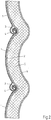
- Fig. 1 shows a part of a roller shutter curtain according to the invention, in which a roller shutter slat 1 made of a single-walled, thin sheet of metal is shown in the middle, and the shutter slats 1, only half shown, are connected upwards and downwards.
- This composite of single-walled, thin roller shutter bars 1 is connected on one side by means of a continuous web 2 made of a flexible material, the dimensions of which correspond to those of the entire roller shutter curtain.
- the roller shutter slats 1 In order to provide joints with as little play as possible, the roller shutter slats 1 have a receiving hook 3 on their underside and a connecting hook 4 on their upper side, which, as shown, correspond to one another.
- the flexible web 2 spans the inevitably arising air gap in the area of both hooks 3, 4 and thus ensures a completely closed roller shutter curtain. Due to the fact that the pivot point is very close to the flexible sheet 2, there are almost no bulges in the flexible sheet 2 in the area of the joints.
- the play-free connection of the individual roller shutter slats 1 also increases the soundproofing, since "rattling" etc. The influence of wind when the roller shutter is lowered cannot lead to a relative movement of the individual roller shutter slats 1 to one another.
- the full-surface cover layer of the flexible web 2 also results in improved soundproofing when the roller shutter curtain according to the invention is wound up or unwound.
- FIG. 2 Another exemplary embodiment of a roller shutter curtain is shown in which a heat-insulating layer (thermal insulation) 5 is applied to the flexible web 2 and is covered by a continuous lamination 6.
- the representation of the heat insulating layer 5 is for Better understanding exaggerated, in practice, especially in passive house construction, significantly lower thicknesses of heat-insulating layers are sufficient.
- a rolled-up roller shutter curtain is shown.
- the extremely thin roller shutter slats 1 of the roller shutter curtain shown according to the invention have a very small barrel diameter when wound up due to their curved shape and their thickness. This can be further improved by using a circular winding shaft 7.
- Tests by the applicant have shown that, for example, a roller shutter curtain according to the invention with a length of 2 m only has a barrel diameter of 115 mm.
- a one meter long roller shutter curtain - i.e. only half as long - has a larger barrel diameter than the 115 mm mentioned above.
Landscapes
- Engineering & Computer Science (AREA)
- Structural Engineering (AREA)
- Architecture (AREA)
- Civil Engineering (AREA)
- Operating, Guiding And Securing Of Roll- Type Closing Members (AREA)
- Laminated Bodies (AREA)
Description
- Die vorliegende Erfindung betrifft einen Rollladenpanzer mit einer Mehrzahl von parallel angeordneten und miteinander jeweils benachbart gelenkig verbundenen Rollladenstäben, wobei jeder Rollladenstab mit korrespondierenden Haken/Haken-Verbindungen versehen ist, wobei jeder Rollladenstab an seiner einen Längsseite einen Aufnahmehaken und an seiner anderen Längsseite einen Verbindungshaken aufweist und wobei jeder Rollladenstab aus einem einwandigen, dünnen Metallblech besteht.
- Rollladen und Rollladenpanzer sind aus der Praxis in vielerlei Ausführungen seit langem bekannt.
- Ein gattungsgemäßer Rollladen mit allen Merkmalen des Oberbegriffs von Anspruch 1 ist aus der
DE 947 021 B bekannt. Dort sind die einzelnen mit korrespondierenden Haken/Haken-Verbindungen verbundenen Rollladenstäbe an ihren Rückseiten mittels bandförmiger Überzüge miteinander verbunden. - Die
DE 19 83 254 U vermittelt die Lehre, Rollläden, bei denen die Stäbe in der Senkrechten durch Gurte oder Drahtglieder in einem vorgegebenen Abstand zusammengehalten werden, durch eine Rollladen zu ersetzen, bei dem die Stäbe mittels einer biegsamen Folie, jedoch auch zueinander beabstandet, zusammengehalten werden. Hierbei wird das Aufbringen der Folie vorgenommen, wenn der Rollladen voll gestreckt, also mit Zwischenräumen versehen ist. Ein Fachmann kann diesem Dokument keinen Hinweis auf die erfindungsgemäße Lösung entnehmen. - Ein weiterer Rollladen ist in der
DE 31 04 048 A1 beschrieben. Nachteilig an diesem bekannten Rollladen ist die Ausbildung der Rollladenstäbe in Leistenform, da die relativ große Rollladenstabstärke einen relativ großen Ballendurchmesser des aufgewickelten Rollladenpanzers zur Folge hat, was insbesondere beim Nachrüsten von Rollladen oder beim Einsatz für den Passivhausbau von Nachteil ist. - Als weiterer Stand der Technik sind aus der
EP 1 048 817 A1 ein "Verfahren zur Herstellung eines Metallfolien-/Gewebeverbundes insbesondere für Rollladenpanzer" und aus derDE 20 2011 000 024 ein "Aufwickelbarer Rollladen" bekannt. - Des Weiteren ist ein Rollladenpanzer bekannt, der aus metallischem Bandmaterial gerollformten und zu mit PU-Schaum gefüllten Hohlprofil-Rollladenstäben, die über ausgebildeten Haken und Taschen mit einander verbunden sind, hergestellt sind. Auch hier ergibt sich zwangsläufig eine größere Rollladenstabstärke und somit ein größerer Ballendurchmesser, der wiederum einen größeren Wickelraum benötigt. Ein weiterer Nachteil dieses Systems ist, dass, um eine seitliche Verschiebung der Rollladenstäbe zu verhindern, eine Arretierung der Rollladenstäbe in deren Längsrichtung notwendig ist.
- Der Erfindung liegt daher die Aufgabe zugrunde, einen Rollladenpanzer der eingangs genannten Art so auszugestalten und weiterzubilden, dass er einen geringeren Ballendurchmesser, eine bessere Wärmedämmung und einen höheren Schallschutz aufweist, sowie kostengünstiger und schneller hergestellt werden kann. Auch soll er ein geringeres Gewicht haben und die Handhabung erleichtern.
- Gelöst wird diese Aufgabe bei einem Rollladenpanzer mit den Merkmalen des Oberbegriffs von Patentanspruch 1 dadurch, dass jeder Rollladen einen gebogenen Querschnitt aufweist und dass der Verbund aus einwandigen, dünnen die Rollladenstäben einseitig vollflächig und nahezu spielfrei mittels einer durchgehenden Bahn aus einem flexiblen Material verbunden ist.
- Durch die Verwendung eines möglichst dünnen einwandigen Rollladenstabes mit einer Haken/Haken-Verbindung ist es möglich, das Gelenk nahezu spielfrei auszuführen. Weiter kann nur durch die Verbindungsvariante der Drehpunkt möglichst dicht an die Deckschicht gelegt werden, was wiederum vorteilhaft ist, um eine Faltenbildung zu verhindern. Die typische Geräuschentwicklung spielbehafteter Rolladenpanzer wird komplett unterbunden. Bei den heute bekannten Sanierungsmethoden von Gebäuden oder dem Passivhausbau, wo beispielsweise die Wärmedämmung über ein Wärm-Dämm-Verbundsystem erfolgt, ist aufgrund der geringen Masse des Systems und der Notwendigkeit, Fenster und Rollladen in dieser Zone zu montieren, eine schallreduzierte- und platzsparende Lösung möglich. Aufgrund des geringen Ballendurchmessers (kleiner Wickelraum) und des reduzierten Lärmpegels stellt der erfindungsgemäße Rollladenpanzer die optimale Lösung für den Sanierungs- und Passivhausbereich dar.
- Bevorzugt wird der Rollladenpanzer mit der Bahn aus flexiblem Material verklebt.
- Gemäß einer weiteren Ausgestaltung der Erfindung sind die Rollladenstäbe aus Aluminium gefertigt. Hier lässt sich durch Rollformung das entsprechend gewünschte Profil der einwandigen dünnen Rollladenstäbe in bekannter Weise herstellen. Diese Ausführung führt zu einem besonders leichten und damit in der Handhabung verbesserten Rollladen.
- Eine weitere Lehre der Erfindung sieht vor, dass die Bahn aus flexiblem Material auf der Innenseite des Rollladenpanzers angeordnet ist. Bei dieser Ausgestaltung ist die Bahn aus flexiblem Material bei geschlossenem Rollladen nicht dem Wetter ausgesetzt. Darüber hinaus sorgt sie zum Inneren des Hauses für eine gleichmäßige Fläche und bietet so dem Betrachter eine ruhigere und angenehm anmutende Ansicht.
- In einer weiteren Ausgestaltung der Erfindung kann die Bahn aus flexiblem Material aus unterschiedlichen Materialien bestehen, beispielsweise aus einem textilen Material oder einer Folie aus Kunststoff oder Metall. Hierbei können durch die Wahl des Materials der Bahn die Eigenschaften des Rollladens gesteuert werden.
- Bei dem in der
DE 31 04 048 A1 gezeigten Rollladen aus Einzelgliedern mit textiler Deckschicht ist es notwendig, aufgrund der Haken/Taschen-Verbindung des im Ausführungsbeispiel dargestellten Rollladenstabes die Deckschicht in diesem Bereich auszubauchen, um Spiel für das Gelenk zu gewährleisten. Es ist dort zwar auch die Möglichkeit beschrieben, dass durch den Einsatz einer sehr flexiblen Folie auf diese Ausbauchung ("Schlaufe") verzichtet werden kann, dies ist aber nicht wirklich möglich, da die Haken/Taschen-Verbindung für Ihre Funktion stets eine Spaltbildung erfordert. - Nachteilig bei einer derartigen Ausführung ist, dass sich diese Ausbuchtungen der Deckschicht im geschlossenen Zustand sich als Falten darstellen, was gerade bei einer beispielsweise mit Motiven bedruckten Deckschicht als störend und unschön empfunden wird. Weiter führen diese Falten beim Aufwickeln des Rollladens zu einer ungewünschten Materialanhäufung, was den Wickeldurchmesser ungünstig und nicht vorhersehbar beeinflusst. Ruht der Rollladen längere Zeit in dieser Position (aufgewickelt), kommt es zu dauerhaft sichtbaren Knickstellen in der Deckschicht (sog. "Bügelfalten"), die auch im geschlossenem Zustand sichtbar sind. Ein weiterer Nachteil dieser Ausführungsform ist die durch das notwendige Taschenspiel der Gelenke bekannte typische Geräuschentwicklung beim Öffnen und Schließen eines solchen Rollladens. Dies ist häufig ein Grund, warum beispielsweise Hotels meist nicht mit Rollläden ausgestattet werden, da das Öffnen und Schließen zu einer erheblichen Lärmbelästigung der Gäste führt.
- Als nachteilig hat sich weiter gezeigt, dass, wenn die Deckschicht auf der Innenseite angeordnet ist, es in den notwendigen Ausbuchtungen im Bereich der Gelenke zu einer Ansammlung von Abrieb und zum Eintrag von Verschmutzungen durch einen nicht komplett geschlossenen Rollladen kommt. Dies kann zu einer weiteren Lärmpegelerhöhung oder sogar im Extremfall zum Versagen eines Gelenks führen.
- Alle diese Nachteile werden durch den erfindungsgemäßen Rollladenpanzer, insbesondere in seiner Ausführung mit spielfreien Gelenken zuverlässig vermieden.
- Eine weitere Lehre der Erfindung sieht vor, dass die Bahn aus flexiblem Material auch mehrlagig ausgebildet sein kann. Bevorzugt ist dazu auf die Bahn aus flexiblem Material eine wärmeisolierende Schicht aufkaschiert.
- Schließlich sieht eine andere Ausgestaltung der Erfindung vor, dass der Rollladenpanzer so ausgestaltet ist, dass er besonders zweckmäßig auf einer runden Wickelwelle aufgerollt werden kann. Auf diese Weise lässt sich der Ballendurchmesser weiter verringern.
- Die Erfindung wird nachfolgend anhand einer lediglich Ausführungsbeispiele darstellenden Zeichnung näher erläutert. In der Zeichnung zeigen
- Fig. 1
- ein erstes Ausführungsbeispiel eines erfindungsgemäßen Rollladenpanzers im Vertikalschnitt,
- Fig. 2
- ein zweites Ausführungsbeispiel eines erfindungsgemäßen Rollladenpanzers im Vertikalschnitt und
- Fig. 3
- den Rollladenpanzer aus
Fig. 1 in aufgewickeltem Zustand, ebenfalls im Vertikalschnitt. -
Fig. 1 zeigt einen Teil eines erfindungsgemäßen Rollladenpanzers, bei dem mittig ein Rollladenstab 1 aus einem einwandigen, dünnen Metallblech gezeigt ist, und an den sich nur halb gezeigte Rollladenstäbe 1 nach oben und unten anschließen. Dieser Verbund aus einwandigen dünnen Rollladenstäben 1 ist einseitig mittels einer durchgehenden Bahn 2 aus einem flexiblen Material verbunden, deren Abmessungen denen des gesamten Rollladenpanzers entspricht. - Um möglichst spielfreie Gelenke vorzusehen, weisen die Rollladenstäbe 1 an ihrer Unterseite einen Aufnahmehaken 3 und an ihrer Oberseite einen Verbindungshaken 4 auf, die, wie dargestellt, miteinander korrespondieren. Die flexible Bahn 2 überspannt dabei den unweigerlich entstehenden Luftspalt im Bereich beider Haken 3, 4 und sorgt so für einen vollständig geschlossenen Rollladenpanzer. Dadurch, dass der Drehpunkt sehr nah an der flexiblen Bahn 2 liegt, gibt es im Bereich der Gelenke nahezu keine Ausbuchtungen der flexiblen Bahn 2. Durch die spielfreie Verbindung der einzelnen Rollladenstäbe 1 erhöht sich zudem der Schallschutz, da ein "Klappern" etc. durch Windeinfluss bei herabgelassenem Rollladen nicht zu einer Relativbewegung der einzelnen Rollladenstäbe 1 zueinander führen kann. Durch die vollflächige Deckschicht der flexiblen Bahn 2 ergibt sich auch ein verbesserter Schallschutz beim Auf- oder Abwickeln des erfindungsgemäßen Rollladenpanzers.
- In
Fig. 2 ist ein weiteres Ausführungsbeispiel eines Rollladenpanzers gezeigt, bei dem auf die flexible Bahn 2 eine wärmeisolierende Schicht (Wärmedämmung) 5 aufgebracht ist und von einer durchgehenden Kaschierung 6 überdeckt ist. Die Darstellung der wärmeisolierenden Schicht 5 ist zum besseren Verständnis überhöht, in der Praxis, gerade beim Passivhausbau, reichen deutlich geringere Stärken von wärmeisolierenden Schichten aus. - Schließlich ist in
Fig. 3 noch ein aufgewickelter Rollladenpanzer dargestellt. Man erkennt deutlich, dass die erfindungsgemäß äußerst dünnen Rollladenstäbe 1 des dargestellten Rollladenpanzers aufgrund ihrer gebogenen Form und ihrer Stärke aufgewickelt einen sehr geringen Ballendurchmesser haben. Dies lässt sich durch die Verwendung einer kreisrunden Wickelwelle 7 noch verbessern. Versuche der Anmelderin haben ergeben, dass beispielsweise ein erfindungsgemäßer Rollladenpanzer mit einer Länge von 2 m nur einen Ballendurchmesser von 115 mm hat. Zum Vergleich sei ausgeführt, dass bei einer herkömmlichen achteckigen Wickelwelle und einem herkömmlichen Rollladenpanzer mit geschäumten Rollladenstäben bereits ein ein - also nur halb so langer - Meter langer Rollladenpanzer einen größeren Ballendurchmesser hat als die zuvor genannten 115 mm.
Claims (10)
- Rollladenpanzer mit einer Mehrzahl von parallel angeordneten und miteinander jeweils benachbart gelenkig verbundenen Rollladenstäben (1), wobei jeder Rollladenstab (1) mit korrespondierenden Haken/Haken-Verbindungen versehen ist, wobei jeder Rollladenstab (1) an seiner einen Längsseite einen Aufnahmehaken (3) und an seiner anderen Längsseite einen Verbindungshaken (4) aufweist und wobei jeder Rollladenstab (1) aus einem einwandigen, dünnen Metallblech besteht,
dadurch gekennzeichnet, dass jeder Rollladenstab (1) einen gebogenen Querschnitt aufweist und dass der Verbund aus einwandigen, dünnen Rollladenstäben (1) einseitig vollflächig und nahezu spielfrei mittels einer durchgehenden Bahn (2) aus einem flexiblen Material verbunden ist. - Rollladenpanzer nach Anspruch 1,
dadurch gekennzeichnet, dass die Bahn (2) aus flexiblem Material mit der Oberfläche der Rollladenstäbe (1) verklebt ist. - Rollladenpanzer nach Anspruche 1 oder 2,
dadurch gekennzeichnet, dass die Rollladenstäbe (1) aus Aluminium hergestellt sind. - Rollladenpanzer nach einem der Ansprüche 1 bis 3,
dadurch gekennzeichnet, dass die Bahn (2) aus flexiblem Material auf der Innenseite des Rollladenpanzers angeordnet ist. - Rollladenpanzer nach einem der Ansprüche 1 bis 4,
dadurch gekennzeichnet, dass die Bahn (2) aus flexiblem Material aus einem textilen Material besteht. - Rollladenpanzer nach einem der Ansprüche 1 bis 4,
dadurch gekennzeichnet, dass die Bahn (2) aus flexiblem Material aus einer Kunststofffolie besteht. - Rollladenpanzer nach einem der Ansprüche 1 bis 4,
dadurch gekennzeichnet, dass die Bahn (2) aus flexiblem Material aus einer Metallfolie besteht. - Rollladenpanzer nach einem der Ansprüche 1 bis 7,
da durch gekennzeichnet, dass die Bahn (2) aus flexiblem Material mehrlagig ausgebildet ist. - Rollladenpanzer nach Anspruch 8,
da durch gekennzeichnet, dass auf die Bahn (2) aus flexiblem Material eine wärmeisolierende Schicht (5) aufkaschiert ist. - Rollladenpanzer nach einem der Ansprüche 1 bis 9, zur Verwendung mit einer Wickelwelle (7) mit rundem Durchmesser.
Applications Claiming Priority (1)
| Application Number | Priority Date | Filing Date | Title |
|---|---|---|---|
| DE102011115726A DE102011115726A1 (de) | 2011-10-12 | 2011-10-12 | Rollladen mit einer Mehrzahl parallel angeordneter und gelenkig verbundener Rollladenstäbe aus einwandigem, dünnem Metallblech |
Publications (3)
| Publication Number | Publication Date |
|---|---|
| EP2581544A2 EP2581544A2 (de) | 2013-04-17 |
| EP2581544A3 EP2581544A3 (de) | 2013-07-17 |
| EP2581544B1 true EP2581544B1 (de) | 2020-08-12 |
Family
ID=47172308
Family Applications (1)
| Application Number | Title | Priority Date | Filing Date |
|---|---|---|---|
| EP12187784.9A Active EP2581544B1 (de) | 2011-10-12 | 2012-10-09 | Rollladen mit einer Mehrzahl parallel angeordneter und gelenkig verbundener Rollladenstäbe aus einwandigem, dünnem Metallblech |
Country Status (2)
| Country | Link |
|---|---|
| EP (1) | EP2581544B1 (de) |
| DE (1) | DE102011115726A1 (de) |
Families Citing this family (1)
| Publication number | Priority date | Publication date | Assignee | Title |
|---|---|---|---|---|
| WO2022266016A1 (en) * | 2021-06-14 | 2022-12-22 | Qualitas Manufacturing Incorporated | Rolling shutter system |
Family Cites Families (9)
| Publication number | Priority date | Publication date | Assignee | Title |
|---|---|---|---|---|
| DE947021C (de) * | 1953-06-11 | 1956-08-09 | Machill & Co K G Rolladen U Ro | Rolladen |
| CH424133A (de) * | 1965-05-28 | 1966-11-15 | Bolleter Emil | Rolladen |
| DE1983254U (de) * | 1967-12-22 | 1968-04-11 | Else Kern | Mit kunststoff-folien ueberzogener rolladen. |
| DE3104048A1 (de) | 1981-02-06 | 1982-08-19 | Clauss Markisen, 7311 Bissingen | "rolladen" |
| DE8629415U1 (de) * | 1986-11-04 | 1987-01-22 | Rudolf Brauns GmbH & Co KG, 8227 Siegsdorf | Dachflächen-Rolladen |
| DE19918698A1 (de) | 1999-04-26 | 2000-11-02 | Henkenjohann Johann | Verfahren zur Herstellung eines Metallfolien-/Gewebeverbundes insbesondere für Rolladenpanzer |
| JP2004204434A (ja) * | 2002-12-20 | 2004-07-22 | Magx Co Ltd | シャッター用シート |
| DE202010005859U1 (de) * | 2010-10-15 | 2011-02-10 | Bertschinger Gmbh & Co. Kg | Biegbares Flächenelement |
| DE202011000024U1 (de) | 2011-01-06 | 2011-03-17 | SCHÜCO International KG | Aufwickelbarer Rollladen |
-
2011
- 2011-10-12 DE DE102011115726A patent/DE102011115726A1/de not_active Ceased
-
2012
- 2012-10-09 EP EP12187784.9A patent/EP2581544B1/de active Active
Non-Patent Citations (1)
| Title |
|---|
| None * |
Also Published As
| Publication number | Publication date |
|---|---|
| DE102011115726A1 (de) | 2013-04-18 |
| EP2581544A2 (de) | 2013-04-17 |
| EP2581544A3 (de) | 2013-07-17 |
Similar Documents
| Publication | Publication Date | Title |
|---|---|---|
| EP2039871B1 (de) | Rolladen und Glied dafür | |
| EP2268885B1 (de) | Hubtoranordnung sowie torsturz-abdichteinrichtung hierfür | |
| EP2987941B1 (de) | Hubtor | |
| DE102018108694A1 (de) | Senkrecht hängende Baukonstruktionsabdeckung. | |
| DE102010020693A1 (de) | Tor zum Verschließen einer Öffnung in einer Wandung | |
| EP1787003B1 (de) | Lamelle für ein sonnenschutzrollo | |
| DE102011010967A1 (de) | Spaltfreie Rolloeinrichtung | |
| WO2008083778A1 (de) | Rolltor, insbesondere schnell laufendes industrietor, sowie lamelle hierfür und verfahren zu ihrer herstellung | |
| EP2084359A1 (de) | Rolltorpanzerprofilstab mit thermischer trennung, herstellverfahren hierfür sowie damit versehenes rolltor | |
| DE4003359A1 (de) | Rolltor mit einem waermegedaemmt und/oder gepanzerten torblatt-behang | |
| EP2581544A2 (de) | Rollladen mit einer Mehrzahl parallel angeordneter und gelenkig verbundener Rollladenstäbe aus einwandigem, dünnem Metallblech | |
| DE19805272B4 (de) | Einrichtung zum Schützen, Abdecken, Verschließen, Abtrennen o. dgl. Abgrenzen von Bereichen | |
| DE102008019149A1 (de) | Herstellverfahren für einen Rolltorpanzer-Profilstab, damit herstellbarer Profilstab sowie Verwendungen desselben | |
| DE102020101393A1 (de) | Isolationsvorrichtung zum Einbau in Fensteröffnungen von Gebäuden | |
| EP2987940A1 (de) | Tor, insbesondere hubtor, zum verschliessen einer öffnung in einer zwei verschiedene temperaturzonen voneinander trennenden wandung | |
| DE202007003044U1 (de) | Brandschutzvorhang | |
| AT11650U1 (de) | Aufnahmevorrichtung für eine behangeinrichtung | |
| DE102007021942A1 (de) | Rolltor, insbesondere schnell laufendes Industrietor, sowie Lamelle hierfür und Verfahren zu ihrer Herstellung | |
| DE19711318C2 (de) | Rolladen für Türen, Fenster oder dergleichen | |
| EP2504515A2 (de) | Rolloeinrichtung | |
| DE19833031C1 (de) | Rollo | |
| DE202013006232U1 (de) | Tor mit Sandwichplatte | |
| DE202009015511U1 (de) | Montageanordnung für einen Rolladenkasten | |
| WO2018050517A2 (de) | Rollbare isoliervorrichtung | |
| EP0087806A1 (de) | Rolladen zum luftdichten Abdecken von Wandöffnungen durch Ausbildung wenigstens einer ruhenden Luftschicht |
Legal Events
| Date | Code | Title | Description |
|---|---|---|---|
| PUAI | Public reference made under article 153(3) epc to a published international application that has entered the european phase |
Free format text: ORIGINAL CODE: 0009012 |
|
| AK | Designated contracting states |
Kind code of ref document: A2 Designated state(s): AL AT BE BG CH CY CZ DE DK EE ES FI FR GB GR HR HU IE IS IT LI LT LU LV MC MK MT NL NO PL PT RO RS SE SI SK SM TR |
|
| AX | Request for extension of the european patent |
Extension state: BA ME |
|
| PUAL | Search report despatched |
Free format text: ORIGINAL CODE: 0009013 |
|
| AK | Designated contracting states |
Kind code of ref document: A3 Designated state(s): AL AT BE BG CH CY CZ DE DK EE ES FI FR GB GR HR HU IE IS IT LI LT LU LV MC MK MT NL NO PL PT RO RS SE SI SK SM TR |
|
| AX | Request for extension of the european patent |
Extension state: BA ME |
|
| RIC1 | Information provided on ipc code assigned before grant |
Ipc: E06B 9/15 20060101AFI20130611BHEP |
|
| 17P | Request for examination filed |
Effective date: 20140117 |
|
| RBV | Designated contracting states (corrected) |
Designated state(s): AL AT BE BG CH CY CZ DE DK EE ES FI FR GB GR HR HU IE IS IT LI LT LU LV MC MK MT NL NO PL PT RO RS SE SI SK SM TR |
|
| 17Q | First examination report despatched |
Effective date: 20141217 |
|
| APBK | Appeal reference recorded |
Free format text: ORIGINAL CODE: EPIDOSNREFNE |
|
| APBN | Date of receipt of notice of appeal recorded |
Free format text: ORIGINAL CODE: EPIDOSNNOA2E |
|
| APAI | Date of receipt of notice of appeal modified |
Free format text: ORIGINAL CODE: EPIDOSCNOA2E |
|
| APBR | Date of receipt of statement of grounds of appeal recorded |
Free format text: ORIGINAL CODE: EPIDOSNNOA3E |
|
| APAF | Appeal reference modified |
Free format text: ORIGINAL CODE: EPIDOSCREFNE |
|
| APBX | Invitation to file observations in appeal sent |
Free format text: ORIGINAL CODE: EPIDOSNOBA2E |
|
| APBZ | Receipt of observations in appeal recorded |
Free format text: ORIGINAL CODE: EPIDOSNOBA4E |
|
| APBT | Appeal procedure closed |
Free format text: ORIGINAL CODE: EPIDOSNNOA9E |
|
| GRAP | Despatch of communication of intention to grant a patent |
Free format text: ORIGINAL CODE: EPIDOSNIGR1 |
|
| STAA | Information on the status of an ep patent application or granted ep patent |
Free format text: STATUS: GRANT OF PATENT IS INTENDED |
|
| INTG | Intention to grant announced |
Effective date: 20200421 |
|
| GRAS | Grant fee paid |
Free format text: ORIGINAL CODE: EPIDOSNIGR3 |
|
| GRAA | (expected) grant |
Free format text: ORIGINAL CODE: 0009210 |
|
| STAA | Information on the status of an ep patent application or granted ep patent |
Free format text: STATUS: THE PATENT HAS BEEN GRANTED |
|
| AK | Designated contracting states |
Kind code of ref document: B1 Designated state(s): AL AT BE BG CH CY CZ DE DK EE ES FI FR GB GR HR HU IE IS IT LI LT LU LV MC MK MT NL NO PL PT RO RS SE SI SK SM TR |
|
| REG | Reference to a national code |
Ref country code: GB Ref legal event code: FG4D Free format text: NOT ENGLISH |
|
| REG | Reference to a national code |
Ref country code: CH Ref legal event code: EP |
|
| REG | Reference to a national code |
Ref country code: CH Ref legal event code: NV Representative=s name: SCHMAUDER AND PARTNER AG PATENT- UND MARKENANW, CH |
|
| REG | Reference to a national code |
Ref country code: NL Ref legal event code: FP Ref country code: IE Ref legal event code: FG4D Free format text: LANGUAGE OF EP DOCUMENT: GERMAN |
|
| REG | Reference to a national code |
Ref country code: DE Ref legal event code: R096 Ref document number: 502012016283 Country of ref document: DE |
|
| REG | Reference to a national code |
Ref country code: AT Ref legal event code: REF Ref document number: 1301713 Country of ref document: AT Kind code of ref document: T Effective date: 20200915 |
|
| REG | Reference to a national code |
Ref country code: LT Ref legal event code: MG4D |
|
| PG25 | Lapsed in a contracting state [announced via postgrant information from national office to epo] |
Ref country code: HR Free format text: LAPSE BECAUSE OF FAILURE TO SUBMIT A TRANSLATION OF THE DESCRIPTION OR TO PAY THE FEE WITHIN THE PRESCRIBED TIME-LIMIT Effective date: 20200812 Ref country code: SE Free format text: LAPSE BECAUSE OF FAILURE TO SUBMIT A TRANSLATION OF THE DESCRIPTION OR TO PAY THE FEE WITHIN THE PRESCRIBED TIME-LIMIT Effective date: 20200812 Ref country code: LT Free format text: LAPSE BECAUSE OF FAILURE TO SUBMIT A TRANSLATION OF THE DESCRIPTION OR TO PAY THE FEE WITHIN THE PRESCRIBED TIME-LIMIT Effective date: 20200812 Ref country code: FI Free format text: LAPSE BECAUSE OF FAILURE TO SUBMIT A TRANSLATION OF THE DESCRIPTION OR TO PAY THE FEE WITHIN THE PRESCRIBED TIME-LIMIT Effective date: 20200812 Ref country code: NO Free format text: LAPSE BECAUSE OF FAILURE TO SUBMIT A TRANSLATION OF THE DESCRIPTION OR TO PAY THE FEE WITHIN THE PRESCRIBED TIME-LIMIT Effective date: 20201112 Ref country code: BG Free format text: LAPSE BECAUSE OF FAILURE TO SUBMIT A TRANSLATION OF THE DESCRIPTION OR TO PAY THE FEE WITHIN THE PRESCRIBED TIME-LIMIT Effective date: 20201112 Ref country code: ES Free format text: LAPSE BECAUSE OF FAILURE TO SUBMIT A TRANSLATION OF THE DESCRIPTION OR TO PAY THE FEE WITHIN THE PRESCRIBED TIME-LIMIT Effective date: 20200812 Ref country code: GR Free format text: LAPSE BECAUSE OF FAILURE TO SUBMIT A TRANSLATION OF THE DESCRIPTION OR TO PAY THE FEE WITHIN THE PRESCRIBED TIME-LIMIT Effective date: 20201113 |
|
| PG25 | Lapsed in a contracting state [announced via postgrant information from national office to epo] |
Ref country code: IS Free format text: LAPSE BECAUSE OF FAILURE TO SUBMIT A TRANSLATION OF THE DESCRIPTION OR TO PAY THE FEE WITHIN THE PRESCRIBED TIME-LIMIT Effective date: 20201212 Ref country code: RS Free format text: LAPSE BECAUSE OF FAILURE TO SUBMIT A TRANSLATION OF THE DESCRIPTION OR TO PAY THE FEE WITHIN THE PRESCRIBED TIME-LIMIT Effective date: 20200812 Ref country code: PL Free format text: LAPSE BECAUSE OF FAILURE TO SUBMIT A TRANSLATION OF THE DESCRIPTION OR TO PAY THE FEE WITHIN THE PRESCRIBED TIME-LIMIT Effective date: 20200812 Ref country code: LV Free format text: LAPSE BECAUSE OF FAILURE TO SUBMIT A TRANSLATION OF THE DESCRIPTION OR TO PAY THE FEE WITHIN THE PRESCRIBED TIME-LIMIT Effective date: 20200812 |
|
| PG25 | Lapsed in a contracting state [announced via postgrant information from national office to epo] |
Ref country code: SM Free format text: LAPSE BECAUSE OF FAILURE TO SUBMIT A TRANSLATION OF THE DESCRIPTION OR TO PAY THE FEE WITHIN THE PRESCRIBED TIME-LIMIT Effective date: 20200812 Ref country code: RO Free format text: LAPSE BECAUSE OF FAILURE TO SUBMIT A TRANSLATION OF THE DESCRIPTION OR TO PAY THE FEE WITHIN THE PRESCRIBED TIME-LIMIT Effective date: 20200812 Ref country code: EE Free format text: LAPSE BECAUSE OF FAILURE TO SUBMIT A TRANSLATION OF THE DESCRIPTION OR TO PAY THE FEE WITHIN THE PRESCRIBED TIME-LIMIT Effective date: 20200812 Ref country code: DK Free format text: LAPSE BECAUSE OF FAILURE TO SUBMIT A TRANSLATION OF THE DESCRIPTION OR TO PAY THE FEE WITHIN THE PRESCRIBED TIME-LIMIT Effective date: 20200812 Ref country code: CZ Free format text: LAPSE BECAUSE OF FAILURE TO SUBMIT A TRANSLATION OF THE DESCRIPTION OR TO PAY THE FEE WITHIN THE PRESCRIBED TIME-LIMIT Effective date: 20200812 |
|
| REG | Reference to a national code |
Ref country code: DE Ref legal event code: R097 Ref document number: 502012016283 Country of ref document: DE |
|
| PG25 | Lapsed in a contracting state [announced via postgrant information from national office to epo] |
Ref country code: AL Free format text: LAPSE BECAUSE OF FAILURE TO SUBMIT A TRANSLATION OF THE DESCRIPTION OR TO PAY THE FEE WITHIN THE PRESCRIBED TIME-LIMIT Effective date: 20200812 |
|
| PLBE | No opposition filed within time limit |
Free format text: ORIGINAL CODE: 0009261 |
|
| STAA | Information on the status of an ep patent application or granted ep patent |
Free format text: STATUS: NO OPPOSITION FILED WITHIN TIME LIMIT |
|
| PG25 | Lapsed in a contracting state [announced via postgrant information from national office to epo] |
Ref country code: SK Free format text: LAPSE BECAUSE OF FAILURE TO SUBMIT A TRANSLATION OF THE DESCRIPTION OR TO PAY THE FEE WITHIN THE PRESCRIBED TIME-LIMIT Effective date: 20200812 Ref country code: MC Free format text: LAPSE BECAUSE OF FAILURE TO SUBMIT A TRANSLATION OF THE DESCRIPTION OR TO PAY THE FEE WITHIN THE PRESCRIBED TIME-LIMIT Effective date: 20200812 |
|
| 26N | No opposition filed |
Effective date: 20210514 |
|
| PG25 | Lapsed in a contracting state [announced via postgrant information from national office to epo] |
Ref country code: IT Free format text: LAPSE BECAUSE OF FAILURE TO SUBMIT A TRANSLATION OF THE DESCRIPTION OR TO PAY THE FEE WITHIN THE PRESCRIBED TIME-LIMIT Effective date: 20200812 |
|
| PG25 | Lapsed in a contracting state [announced via postgrant information from national office to epo] |
Ref country code: SI Free format text: LAPSE BECAUSE OF FAILURE TO SUBMIT A TRANSLATION OF THE DESCRIPTION OR TO PAY THE FEE WITHIN THE PRESCRIBED TIME-LIMIT Effective date: 20200812 |
|
| PG25 | Lapsed in a contracting state [announced via postgrant information from national office to epo] |
Ref country code: TR Free format text: LAPSE BECAUSE OF FAILURE TO SUBMIT A TRANSLATION OF THE DESCRIPTION OR TO PAY THE FEE WITHIN THE PRESCRIBED TIME-LIMIT Effective date: 20200812 Ref country code: MT Free format text: LAPSE BECAUSE OF FAILURE TO SUBMIT A TRANSLATION OF THE DESCRIPTION OR TO PAY THE FEE WITHIN THE PRESCRIBED TIME-LIMIT Effective date: 20200812 Ref country code: CY Free format text: LAPSE BECAUSE OF FAILURE TO SUBMIT A TRANSLATION OF THE DESCRIPTION OR TO PAY THE FEE WITHIN THE PRESCRIBED TIME-LIMIT Effective date: 20200812 |
|
| PG25 | Lapsed in a contracting state [announced via postgrant information from national office to epo] |
Ref country code: MK Free format text: LAPSE BECAUSE OF FAILURE TO SUBMIT A TRANSLATION OF THE DESCRIPTION OR TO PAY THE FEE WITHIN THE PRESCRIBED TIME-LIMIT Effective date: 20200812 |
|
| PG25 | Lapsed in a contracting state [announced via postgrant information from national office to epo] |
Ref country code: PT Free format text: LAPSE BECAUSE OF FAILURE TO SUBMIT A TRANSLATION OF THE DESCRIPTION OR TO PAY THE FEE WITHIN THE PRESCRIBED TIME-LIMIT Effective date: 20200812 |
|
| PGFP | Annual fee paid to national office [announced via postgrant information from national office to epo] |
Ref country code: NL Payment date: 20221024 Year of fee payment: 11 |
|
| PGFP | Annual fee paid to national office [announced via postgrant information from national office to epo] |
Ref country code: LU Payment date: 20221024 Year of fee payment: 11 Ref country code: IE Payment date: 20221025 Year of fee payment: 11 Ref country code: GB Payment date: 20221024 Year of fee payment: 11 Ref country code: AT Payment date: 20221025 Year of fee payment: 11 |
|
| PGFP | Annual fee paid to national office [announced via postgrant information from national office to epo] |
Ref country code: CH Payment date: 20221026 Year of fee payment: 11 Ref country code: BE Payment date: 20221024 Year of fee payment: 11 |
|
| P01 | Opt-out of the competence of the unified patent court (upc) registered |
Effective date: 20230514 |
|
| REG | Reference to a national code |
Ref country code: CH Ref legal event code: PL |
|
| REG | Reference to a national code |
Ref country code: NL Ref legal event code: MM Effective date: 20231101 |
|
| REG | Reference to a national code |
Ref country code: AT Ref legal event code: MM01 Ref document number: 1301713 Country of ref document: AT Kind code of ref document: T Effective date: 20231009 |
|
| REG | Reference to a national code |
Ref country code: BE Ref legal event code: MM Effective date: 20231031 |
|
| PG25 | Lapsed in a contracting state [announced via postgrant information from national office to epo] |
Ref country code: LU Free format text: LAPSE BECAUSE OF NON-PAYMENT OF DUE FEES Effective date: 20231009 |
|
| GBPC | Gb: european patent ceased through non-payment of renewal fee |
Effective date: 20231009 |
|
| PG25 | Lapsed in a contracting state [announced via postgrant information from national office to epo] |
Ref country code: LU Free format text: LAPSE BECAUSE OF NON-PAYMENT OF DUE FEES Effective date: 20231009 |
|
| PG25 | Lapsed in a contracting state [announced via postgrant information from national office to epo] |
Ref country code: GB Free format text: LAPSE BECAUSE OF NON-PAYMENT OF DUE FEES Effective date: 20231009 |
|
| PG25 | Lapsed in a contracting state [announced via postgrant information from national office to epo] |
Ref country code: CH Free format text: LAPSE BECAUSE OF NON-PAYMENT OF DUE FEES Effective date: 20231031 Ref country code: NL Free format text: LAPSE BECAUSE OF NON-PAYMENT OF DUE FEES Effective date: 20231101 |
|
| PG25 | Lapsed in a contracting state [announced via postgrant information from national office to epo] |
Ref country code: AT Free format text: LAPSE BECAUSE OF NON-PAYMENT OF DUE FEES Effective date: 20231009 |
|
| PG25 | Lapsed in a contracting state [announced via postgrant information from national office to epo] |
Ref country code: NL Free format text: LAPSE BECAUSE OF NON-PAYMENT OF DUE FEES Effective date: 20231101 Ref country code: GB Free format text: LAPSE BECAUSE OF NON-PAYMENT OF DUE FEES Effective date: 20231009 Ref country code: CH Free format text: LAPSE BECAUSE OF NON-PAYMENT OF DUE FEES Effective date: 20231031 Ref country code: AT Free format text: LAPSE BECAUSE OF NON-PAYMENT OF DUE FEES Effective date: 20231009 |
|
| PG25 | Lapsed in a contracting state [announced via postgrant information from national office to epo] |
Ref country code: BE Free format text: LAPSE BECAUSE OF NON-PAYMENT OF DUE FEES Effective date: 20231031 |
|
| PG25 | Lapsed in a contracting state [announced via postgrant information from national office to epo] |
Ref country code: IE Free format text: LAPSE BECAUSE OF NON-PAYMENT OF DUE FEES Effective date: 20231009 |
|
| PG25 | Lapsed in a contracting state [announced via postgrant information from national office to epo] |
Ref country code: IE Free format text: LAPSE BECAUSE OF NON-PAYMENT OF DUE FEES Effective date: 20231009 |
|
| PGFP | Annual fee paid to national office [announced via postgrant information from national office to epo] |
Ref country code: DE Payment date: 20251021 Year of fee payment: 14 |
|
| PGFP | Annual fee paid to national office [announced via postgrant information from national office to epo] |
Ref country code: FR Payment date: 20251021 Year of fee payment: 14 |