EP2572902B1 - Luftreifen und Herstellungsverfahren dafür - Google Patents
Luftreifen und Herstellungsverfahren dafür Download PDFInfo
- Publication number
- EP2572902B1 EP2572902B1 EP12178010.0A EP12178010A EP2572902B1 EP 2572902 B1 EP2572902 B1 EP 2572902B1 EP 12178010 A EP12178010 A EP 12178010A EP 2572902 B1 EP2572902 B1 EP 2572902B1
- Authority
- EP
- European Patent Office
- Prior art keywords
- rubber
- width direction
- tire width
- tire
- conductive
- Prior art date
- Legal status (The legal status is an assumption and is not a legal conclusion. Google has not performed a legal analysis and makes no representation as to the accuracy of the status listed.)
- Not-in-force
Links
- 238000004519 manufacturing process Methods 0.000 title claims description 17
- 229920001971 elastomer Polymers 0.000 claims description 358
- 239000005060 rubber Substances 0.000 claims description 358
- 238000004804 winding Methods 0.000 claims description 70
- 230000002093 peripheral effect Effects 0.000 claims description 39
- 238000000034 method Methods 0.000 claims description 37
- 239000011324 bead Substances 0.000 claims description 17
- 239000010410 layer Substances 0.000 description 38
- VYPSYNLAJGMNEJ-UHFFFAOYSA-N Silicium dioxide Chemical compound O=[Si]=O VYPSYNLAJGMNEJ-UHFFFAOYSA-N 0.000 description 17
- 238000001125 extrusion Methods 0.000 description 13
- 230000000052 comparative effect Effects 0.000 description 10
- 238000010276 construction Methods 0.000 description 9
- 239000000377 silicon dioxide Substances 0.000 description 8
- 230000006866 deterioration Effects 0.000 description 7
- 230000003014 reinforcing effect Effects 0.000 description 6
- 238000005096 rolling process Methods 0.000 description 6
- 239000006229 carbon black Substances 0.000 description 5
- 239000000463 material Substances 0.000 description 5
- 229910052751 metal Inorganic materials 0.000 description 5
- 239000002184 metal Substances 0.000 description 5
- 238000002156 mixing Methods 0.000 description 4
- 230000003068 static effect Effects 0.000 description 4
- 230000005611 electricity Effects 0.000 description 3
- 238000000465 moulding Methods 0.000 description 3
- 239000002994 raw material Substances 0.000 description 3
- VTYYLEPIZMXCLO-UHFFFAOYSA-L Calcium carbonate Chemical compound [Ca+2].[O-]C([O-])=O VTYYLEPIZMXCLO-UHFFFAOYSA-L 0.000 description 2
- OKTJSMMVPCPJKN-UHFFFAOYSA-N Carbon Chemical compound [C] OKTJSMMVPCPJKN-UHFFFAOYSA-N 0.000 description 2
- 239000005062 Polybutadiene Substances 0.000 description 2
- 230000015572 biosynthetic process Effects 0.000 description 2
- 229920005549 butyl rubber Polymers 0.000 description 2
- 239000004927 clay Substances 0.000 description 2
- 238000007599 discharging Methods 0.000 description 2
- 230000000694 effects Effects 0.000 description 2
- 238000011156 evaluation Methods 0.000 description 2
- 239000000945 filler Substances 0.000 description 2
- 230000002401 inhibitory effect Effects 0.000 description 2
- 229920003049 isoprene rubber Polymers 0.000 description 2
- 229920002857 polybutadiene Polymers 0.000 description 2
- 238000003825 pressing Methods 0.000 description 2
- 239000012744 reinforcing agent Substances 0.000 description 2
- 239000002356 single layer Substances 0.000 description 2
- 229920000049 Carbon (fiber) Polymers 0.000 description 1
- 229920001875 Ebonite Polymers 0.000 description 1
- 244000043261 Hevea brasiliensis Species 0.000 description 1
- 229910000831 Steel Inorganic materials 0.000 description 1
- 230000003187 abdominal effect Effects 0.000 description 1
- 239000003963 antioxidant agent Substances 0.000 description 1
- 230000003078 antioxidant effect Effects 0.000 description 1
- 229910000019 calcium carbonate Inorganic materials 0.000 description 1
- 229910052799 carbon Inorganic materials 0.000 description 1
- 239000004917 carbon fiber Substances 0.000 description 1
- 239000003795 chemical substances by application Substances 0.000 description 1
- 230000002708 enhancing effect Effects 0.000 description 1
- 238000010070 extrusion (rubber) Methods 0.000 description 1
- 239000000835 fiber Substances 0.000 description 1
- 239000000446 fuel Substances 0.000 description 1
- 229910002804 graphite Inorganic materials 0.000 description 1
- 239000010439 graphite Substances 0.000 description 1
- 238000009434 installation Methods 0.000 description 1
- 229910044991 metal oxide Inorganic materials 0.000 description 1
- 150000004706 metal oxides Chemical class 0.000 description 1
- VNWKTOKETHGBQD-UHFFFAOYSA-N methane Chemical compound C VNWKTOKETHGBQD-UHFFFAOYSA-N 0.000 description 1
- 229920003052 natural elastomer Polymers 0.000 description 1
- 229920001194 natural rubber Polymers 0.000 description 1
- 239000004014 plasticizer Substances 0.000 description 1
- 239000000843 powder Substances 0.000 description 1
- 239000012779 reinforcing material Substances 0.000 description 1
- 239000010959 steel Substances 0.000 description 1
- 229920003048 styrene butadiene rubber Polymers 0.000 description 1
- 238000010998 test method Methods 0.000 description 1
Images


Classifications
-
- B—PERFORMING OPERATIONS; TRANSPORTING
- B60—VEHICLES IN GENERAL
- B60C—VEHICLE TYRES; TYRE INFLATION; TYRE CHANGING; CONNECTING VALVES TO INFLATABLE ELASTIC BODIES IN GENERAL; DEVICES OR ARRANGEMENTS RELATED TO TYRES
- B60C19/00—Tyre parts or constructions not otherwise provided for
- B60C19/08—Electric-charge-dissipating arrangements
- B60C19/082—Electric-charge-dissipating arrangements comprising a conductive tread insert
-
- B—PERFORMING OPERATIONS; TRANSPORTING
- B29—WORKING OF PLASTICS; WORKING OF SUBSTANCES IN A PLASTIC STATE IN GENERAL
- B29D—PRODUCING PARTICULAR ARTICLES FROM PLASTICS OR FROM SUBSTANCES IN A PLASTIC STATE
- B29D30/00—Producing pneumatic or solid tyres or parts thereof
- B29D30/06—Pneumatic tyres or parts thereof (e.g. produced by casting, moulding, compression moulding, injection moulding, centrifugal casting)
- B29D30/52—Unvulcanised treads, e.g. on used tyres; Retreading
- B29D30/58—Applying bands of rubber treads, i.e. applying camel backs
- B29D30/60—Applying bands of rubber treads, i.e. applying camel backs by winding narrow strips
-
- B—PERFORMING OPERATIONS; TRANSPORTING
- B60—VEHICLES IN GENERAL
- B60C—VEHICLE TYRES; TYRE INFLATION; TYRE CHANGING; CONNECTING VALVES TO INFLATABLE ELASTIC BODIES IN GENERAL; DEVICES OR ARRANGEMENTS RELATED TO TYRES
- B60C11/00—Tyre tread bands; Tread patterns; Anti-skid inserts
- B60C11/0041—Tyre tread bands; Tread patterns; Anti-skid inserts comprising different tread rubber layers
- B60C11/005—Tyre tread bands; Tread patterns; Anti-skid inserts comprising different tread rubber layers with cap and base layers
-
- B—PERFORMING OPERATIONS; TRANSPORTING
- B60—VEHICLES IN GENERAL
- B60C—VEHICLE TYRES; TYRE INFLATION; TYRE CHANGING; CONNECTING VALVES TO INFLATABLE ELASTIC BODIES IN GENERAL; DEVICES OR ARRANGEMENTS RELATED TO TYRES
- B60C11/00—Tyre tread bands; Tread patterns; Anti-skid inserts
- B60C11/03—Tread patterns
- B60C11/0304—Asymmetric patterns
-
- B—PERFORMING OPERATIONS; TRANSPORTING
- B60—VEHICLES IN GENERAL
- B60C—VEHICLE TYRES; TYRE INFLATION; TYRE CHANGING; CONNECTING VALVES TO INFLATABLE ELASTIC BODIES IN GENERAL; DEVICES OR ARRANGEMENTS RELATED TO TYRES
- B60C13/00—Tyre sidewalls; Protecting, decorating, marking, or the like, thereof
-
- B—PERFORMING OPERATIONS; TRANSPORTING
- B60—VEHICLES IN GENERAL
- B60C—VEHICLE TYRES; TYRE INFLATION; TYRE CHANGING; CONNECTING VALVES TO INFLATABLE ELASTIC BODIES IN GENERAL; DEVICES OR ARRANGEMENTS RELATED TO TYRES
- B60C15/00—Tyre beads, e.g. ply turn-up or overlap
-
- B—PERFORMING OPERATIONS; TRANSPORTING
- B60—VEHICLES IN GENERAL
- B60C—VEHICLE TYRES; TYRE INFLATION; TYRE CHANGING; CONNECTING VALVES TO INFLATABLE ELASTIC BODIES IN GENERAL; DEVICES OR ARRANGEMENTS RELATED TO TYRES
- B60C19/00—Tyre parts or constructions not otherwise provided for
- B60C19/08—Electric-charge-dissipating arrangements
- B60C19/084—Electric-charge-dissipating arrangements using conductive carcasses
-
- B—PERFORMING OPERATIONS; TRANSPORTING
- B60—VEHICLES IN GENERAL
- B60C—VEHICLE TYRES; TYRE INFLATION; TYRE CHANGING; CONNECTING VALVES TO INFLATABLE ELASTIC BODIES IN GENERAL; DEVICES OR ARRANGEMENTS RELATED TO TYRES
- B60C19/00—Tyre parts or constructions not otherwise provided for
- B60C19/08—Electric-charge-dissipating arrangements
- B60C19/086—Electric-charge-dissipating arrangements using conductive sidewalls
-
- B—PERFORMING OPERATIONS; TRANSPORTING
- B60—VEHICLES IN GENERAL
- B60C—VEHICLE TYRES; TYRE INFLATION; TYRE CHANGING; CONNECTING VALVES TO INFLATABLE ELASTIC BODIES IN GENERAL; DEVICES OR ARRANGEMENTS RELATED TO TYRES
- B60C19/00—Tyre parts or constructions not otherwise provided for
- B60C19/08—Electric-charge-dissipating arrangements
- B60C19/088—Electric-charge-dissipating arrangements using conductive beads
-
- B—PERFORMING OPERATIONS; TRANSPORTING
- B60—VEHICLES IN GENERAL
- B60C—VEHICLE TYRES; TYRE INFLATION; TYRE CHANGING; CONNECTING VALVES TO INFLATABLE ELASTIC BODIES IN GENERAL; DEVICES OR ARRANGEMENTS RELATED TO TYRES
- B60C9/00—Reinforcements or ply arrangement of pneumatic tyres
- B60C9/02—Carcasses
-
- B—PERFORMING OPERATIONS; TRANSPORTING
- B29—WORKING OF PLASTICS; WORKING OF SUBSTANCES IN A PLASTIC STATE IN GENERAL
- B29D—PRODUCING PARTICULAR ARTICLES FROM PLASTICS OR FROM SUBSTANCES IN A PLASTIC STATE
- B29D30/00—Producing pneumatic or solid tyres or parts thereof
- B29D30/06—Pneumatic tyres or parts thereof (e.g. produced by casting, moulding, compression moulding, injection moulding, centrifugal casting)
- B29D30/52—Unvulcanised treads, e.g. on used tyres; Retreading
- B29D2030/526—Unvulcanised treads, e.g. on used tyres; Retreading the tread comprising means for discharging the electrostatic charge, e.g. conductive elements or portions having conductivity higher than the tread rubber
-
- B—PERFORMING OPERATIONS; TRANSPORTING
- B60—VEHICLES IN GENERAL
- B60C—VEHICLE TYRES; TYRE INFLATION; TYRE CHANGING; CONNECTING VALVES TO INFLATABLE ELASTIC BODIES IN GENERAL; DEVICES OR ARRANGEMENTS RELATED TO TYRES
- B60C11/00—Tyre tread bands; Tread patterns; Anti-skid inserts
- B60C11/03—Tread patterns
- B60C2011/0337—Tread patterns characterised by particular design features of the pattern
- B60C2011/0339—Grooves
- B60C2011/0341—Circumferential grooves
Definitions
- the present invention relates to a pneumatic tire which can discharge static electricity generated in a vehicle body and a tire, to a road surface, and a manufacturing method of the pneumatic tire.
- a pneumatic tire including a tread rubber blended with silica at a high ratio in order to reduce the rolling resistance that largely affects the fuel consumption of a vehicle and/or to increase braking performance (WET braking performance) on a wet road surface.
- WET braking performance braking performance
- a pneumatic tire structured such that a tread rubber constructed by a nonconductive rubber blended with a silica or the like is provided with a conductive portion constructed by a conductive rubber blended with a carbon black or the like, whereby an electrical conduction performance can be achieved.
- a conductive portion extending in a tire radial direction from a ground-contacting surface so as to reach a belt layer is provided in a tread rubber which is formed by a non-conductive rubber, thereby forming a conductive route for discharging a static electricity.
- the conductive route is formed via the belt layer, it can not correspond to the case that a topping rubber of the belt layer is formed by a non-conductive rubber.
- a tread rubber formed by a non-conductive rubber is provided with a conductive portion which extends to an inner side in a tire radial direction from a ground-contacting surface, extends only to one side in a tire width direction between a cap portion and a base portion, and is connected to a side wall rubber or a topping rubber in a carcass layer.
- the conductive portion formed as an L-shaped cross sectional form as mentioned above wherein it is formed such in a shape as to be one-sided in the tire width direction there has been found that it causes a reduction of productivity and a deterioration of uniformity.
- the present invention has been made by taking the actual condition mentioned above into consideration, and an object of the present invention is to provide a pneumatic tire which can well achieve an electrical conduction performance by preventing a covered state, as well as suppressing a reduction of a productivity and a deterioration of a uniformity, and a manufacturing method of such a pneumatic tire.
- the present invention provides a pneumatic tire comprising a pair of bead portions; side wall portions each of which extends to an outer side in a tire radial direction from each of the bead portions; a tread portion which is connected to an outer end in the tire radial direction of each of the side wall portions; a toroidal carcass layer which is provided between the pair of bead portions; a side wall rubber which is provided in an outer side of the carcass layer in the side wall portion; and a tread rubber which is provided in an outer side of the carcass layer in the tread portion; wherein the tread rubber has a cap portion which is formed by a nonconductive rubber and constructs a ground-contacting surface, a base portion which is formed by the nonconductive rubber and is provided in an inner side in the tire radial direction of the cap portion, and a pair of conductive portions which are formed by a conductive rubber and are exposed in the ground-contacting surface; and wherein the pair of conductive portions comprises a first
- a pair of conductive portions which are provided in the tread rubber are constructed by the first conductive portion and the second conductive portion as mentioned above, and the conductive portions are formed respectively on the one side and the other side in the tire width direction.
- the thickness of the cap portion and the rigidity of the tread rubber are not greatly different between the right and left sides, and it is possible to suppress the reduction of the productivity and the deterioration of the uniformity.
- the exposed positions on the ground-contacting surface of the first and second conductive portions are away from the tire equator at the distance which is equal to or more than 10 % of the ground-contacting width, it is possible to well achieve the electrical conduction performance by preventing the covered state.
- a circumferential main groove is formed on a surface of the tread rubber, while avoiding a section in which the first conductive portion and the second conductive portion extend to the inner side in the tire radial direction from the ground-contacting surface so as to reach an outer peripheral surface of the base portion.
- a groove area of a region which comes to one side in the tire width direction of the ground-contacting surface is larger than a groove area of a region which comes to the other side in the tire width direction based on the tire equator, and a distance from the exposed position on the ground-contacting surface of the first conductive portion to the tire equator is longer than a distance from the exposed position on the ground-contacting surface of the second conductive portion to the tire equator.
- the present invention provides a manufacturing method of a pneumatic tire comprising a forming step of a tread rubber which is provided with a base portion in an inner side in a tire radial direction of a cap portion constructing a ground-contacting surface; wherein the forming step of the tread rubber comprises a stage of forming the base portion by a nonconductive rubber, a stage of forming a first cap portion which comes to one side portion in the tired width direction of the cap portion, by spirally winding a first rubber ribbon constructed by the nonconductive rubber along a tire circumferential direction, on an outer peripheral surface in one side in a tire width direction of the base portion, and a stage of forming a second cap portion which comes to the other side portion in the tire width direction of the cap portion, by spirally winding a second rubber ribbon constructed by the nonconductive rubber along the tire circumferential direction, on an outer peripheral surface in another side in the tire width direction of the base portion; wherein the stage of forming the first cap portion partly sets a conductive rubber in the first rubber ribbon in the
- the first conductive portion and the second conductive portion as mentioned above are simply and easily formed, in the stage of forming the cap portion by winding the rubber ribbon, in the forming step of the tread rubber.
- the winding position of the first rubber ribbon moves to the other side in the tire width direction from a start point which is separated from the tire equator to the one side in the tire width direction, next turns back to the one side in the tire width direction so as to pass through the start point, next passes through an end portion on the one side in the tire width direction of the base portion, and thereafter turns back to the other side in the tire width direction so as to reach an end point
- the conductive rubber for forming the first conductive portion is provided in the first rubber ribbon, in a section from a position which is after turning back to the one side in the tire width direction and before passing through the start point, to a position which passes through the end portion on the one side in the tire width direction of the base portion, or in the stage of forming the second cap portion, the winding position of the second rubber ribbon moves to the one side in the tire width direction from a start point
- the RRO means a change amount in a vertical direction of the rotating shaft at a time of rotating the tire.
- the end portion in the other side in the tire width direction of the first cap portion is formed as a tapered shape in the stage of forming the first cap portion, and the end portion on the one side in the tire width direction of the second cap portion is formed so as to be overlapped with the end portion in the other side in the tire width direction of the first cap portion, in the stage of forming the second cap portion.
- the forming step of the tread rubber includes a stage of forming a third cap portion which comes to a center portion in the tire width direction of the cap portion by the nonconductive rubber, and the end portion in the other side in the tire width direction of the first cap portion is overlapped with the end portion on the one side in the tire width direction of the third cap portion, and the end portion on the one side in the tire width direction of the second cap portion is overlapped with the end portion in the other side in the tire width direction of the third cap portion.
- the forming step of the tread rubber includes a stage of forming a third cap portion which comes to a center portion in the tire width direction of the cap portion by the nonconductive rubber, and in the stage of forming the first cap portion, the winding position of the first rubber ribbon moves to the other side in the tire width direction from a start point which is separated from the tire equator to the one side in the tire width direction, next turns back to the one side in the tire width direction so as to pass through the start point, next passes through an end portion on the one side in the tire width direction of the base portion, and thereafter turns back to the other side in the tire width direction so as to reach an end point, and the conductive rubber for forming the first conductive portion is provided in the first rubber ribbon, in a section from the start point to a position which turns back to the one side in the tire width direction, and a section which is just after passing through the start point, to a position which passes through the
- both end portions in the tire width direction of the third cap portion are formed as a tapered shape in the stage of forming the third cap portion, the end portion in the other side in the tire width direction of the first cap portion is formed so as to be overlapped with the end portion on the one side in the tire width direction of the third cap portion, in the stage of forming the first cap portion, and the end portion on the one side in the tire width direction of the second cap portion is formed so as to be overlapped with the end portion in the other side in the tire width direction of the third cap portion, in the stage of forming the second cap portion.
- the forming step of the tread rubber includes the stage of forming the inner cap which becomes narrower than the base portion in the center portion in the tire width direction of the outer peripheral surface of the base portion by the non-conductive rubber, and the cap portion is formed in such a manner as to cover the inner cap.
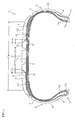
- a pneumatic tire T shown in FIG. 1 is provided with a pair of bead portions 1, side wall portions 2 each of which extends to an outer side in a tire radial direction from each of the bead portions 1, a tread portion 3 which is connected to an outer end in the tire radial direction of each of the side wall portions 2, and a toroidal carcass layer 7 which is provided between a pair of bead portions 1.
- the bead portion 1 includes an annular bead core 1a composed of a bundle of steel wires or the like sheathed with rubber and a bead filler 1b made of hard rubber disposed therein.
- the carcass layer 7 is constructed by at least one (two in the present embodiment) carcass ply, and an end portion thereof is fixed in a state in which it is wound up via a bead core 1a.
- the carcass ply is formed by covering a cord extending at an angle of approximately 90° with respect to the tire circumferential direction with a topping rubber.
- An inner liner rubber 5 for maintaining air pressure is provided on the inside of the carcass layer 7.
- this tire T is provided with a side wall rubber 9 which is provided in an outer side of the carcass layer 7 in the side wall portion 2, and a tread rubber 10 which is provided in an outer side of the carcass layer 7 in the tread portion 3.
- a rim strip rubber 4 which comes into contact with a rim (not shown) at a time of being installed to the rim is provided in an outer side of the carcass layer 7 in the bead portion 1.
- the topping rubber of the carcass layer 7 (the topping rubber of the carcass ply) and the rim strip rubber 4 are formed of conductive rubber respectively, and the side wall rubber 9 is formed of nonconductive rubber.
- An inner side in the tire radial direction of the tread rubber 10 is provided with a belt layer 6 which is constructed by a plurality of (two in the present embodiment) belt plies, and a belt reinforcing layer 8 which is formed by covering a cord extending substantially in a tire circumferential direction with a topping rubber.
- Each of the belt plies is formed by covering a cord extending while inclining with respect to the tire circumferential direction with a topping rubber, and is laminated in such a manner that the cord intersects inversely to each other between the plies.
- a belt reinforcing layer 8 may be omitted as occasion demands.
- the tread rubber 10 has a cap portion 12 which is formed by a nonconductive rubber and constructs a ground-contacting surface, a base portion 11 which is formed by the nonconductive rubber and is provided in an inner side in the tire radial direction of the cap portion 12, and a pair of conductive portions which are formed by a conductive rubber and is exposed in the ground-contacting surface.
- This pair of conductive portions is constructed by a first conductive portion 13 (hereinafter, refer simply to as “conductive portion 13”) and a second conductive portion 14 (hereinafter, refer simply to as “conductive portion 14").
- conductive portion 13 a first conductive portion 13
- conductive portion 14 a second conductive portion 14
- the conductive portion is colored by a black in FIG. 1 and the like.
- the rubber hardness of the tread rubber 10 is not particularly limited, however, it is possible to suppress an early wear by making the rubber hardness of the cap portion 12 higher than the rubber hardness of the base portion 11, for example, thereby setting a hardness difference thereof to 1 to 20 degree.
- the rubber hardness is measured at 25 °C in accordance with a durometer hardness test (type A) of JISK6253.
- the rubber hardness of the base portion 11 may be made higher than the rubber hardness of the cap portion 12.
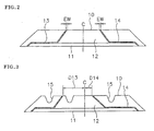
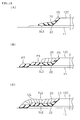
- FIG. 2 schematically shows the tread rubber 10 before the cure molding.
- the conductive rubber points to a rubber in which a specific volume resistance is less than 10 8 Ohm-cm, and is produced, for example, by blending a carbon black serving as a reinforcing agent in a raw material rubber at a high ratio.
- the carbon black is blended, for example, by 30 to 100 phr with respect to 100 phr of the rubber component.
- the conductive rubber can be obtained by blending a predetermined amount of known conductivity applying material such as a carbon including a carbon fiber, a graphite and the like, or a metal including a metal powder, a metal oxide, a metal flake, a metal fiber and the like in addition to the carbon black.
- a conductivity applying material such as a carbon including a carbon fiber, a graphite and the like, or a metal including a metal powder, a metal oxide, a metal flake, a metal fiber and the like in addition to the carbon black.
- the nonconductive rubber points to a rubber in which a specific volume resistance is equal to or more than 10 8 ⁇ cm, and is produced, for example, by blending a silica serving as the reinforcing agent in the raw material rubber at a high ratio.
- the silica is blended, for example, at 30 to 100 phr with respect to 100 phr of the rubber component.
- a wet type silica can be preferably employed, however, any material which is generally used as a reinforcing material can be used without limitation.
- the non-conductive rubber may be produced by blending a calcined clay, a hard clay, a calcium carbonate or the like in addition to the silica such as a precipitated silica, a silicic anhydride or the like.
- the raw material rubber mentioned above the following are exemplified; i.e., natural rubber, styrene-butadiene rubber (SBR), butadiene rubber (BR), isoprene rubber (IR), butyl rubber (IIR) and the like. These materials may be used alone or in combination.
- SBR styrene-butadiene rubber
- BR butadiene rubber
- IR isoprene rubber
- IIR butyl rubber
- the above raw rubber is appropriately blended with a curing agent, a cure accelerator, a plasticizer, an antioxidant and the like.
- the conductive portion 13 extends to an inner side in the tire radial direction from the ground-contacting surface so as to reach an outer peripheral surface of the base portion 11, extends to one side (which may be, hereinafter, often described as "left side") in the tire width direction between the cap portion 12 and the base portion 11, and is connected to a topping rubber of the carcass layer 7.
- An exposed position on the ground-contacting surface of the conductive portion 13 is separated from a tire equator C to the left side at a distance D 13, and the distance D13 is equal to or more than 10 % of a ground-contacting width CW.
- the conductive portion 14 extends to an inner side in the tire radial direction from the ground-contacting surface so as to reach an outer peripheral surface of the base portion 11, extends to the other side (which may be, hereinafter, often described as "right side") in the tire width direction between the cap portion 12 and the base portion 11, and is connected to a topping rubber of the carcass layer 7.
- An exposed position on the ground-contacting surface of the conductive portion 14 is separated from a tire equator C to the right side at a distance D 14, and the distance D14 is equal to or more than 10 % of a ground-contacting width CW.
- the tire T is provided with a conductive route for discharging static electricity to a road surface.
- the conductive route has two ways, one of them is a route which comes to the ground-contacting surface from the rim via the left rim strip rubber 4, the topping rubber of the carcass layer 7 and the conductive portion 13.
- the other route is a route which comes to the ground-contacting surface from the rim via the right rim strip rubber 4, the topping rubber of the carcass layer 7 and the conductive portion 14. Accordingly, it is possible to form the topping rubbers of the belt layer 6 and the belt reinforcing layer 8 by the nonconductive rubber.
- an L-shaped conductive portion is formed in each of the right and left sides of the tread rubber 10, that is, one side and another side in the tire width direction.
- the exposed positions on the ground-contacting surface of the conductive portions 13 and 14 are separated from the tire equator C at a predetermined distance, it is possible to prevent a covered state so as to well achieve an electrical conduction performance.
- the conductive portions 13 and 14 are not exposed in the vicinity of the tire equator C, but are exposed in so-called mediate portions which are separated from the tire equator C at distances D13 and D14, thereby preventing the covered state.
- each of the distances D 13 and D14 is preferably equal to or more than 20 % of the ground-contacting width CW, is more preferably equal to or more than 30 % of the ground-contacting width CW, is further preferably more than 30 % of the ground-contacting width CW, and is further more preferably equal to or more than 40 % of the ground-contacting width CW.
- the exposure width (refer to FIG. 2 ) of the conductive portions 13 and 14 is, for example, between 0.1 mm and 1.0 mm.
- the conductive portion 13 and the conductive portion 14 are not limited to be arranged symmetrically with respect to the tire equator C, but may be arranged asymmetrically as being exemplified later.
- the ground surface to which the conductive portion 13 and 14 are exposed indicates the surface of the tread portion grounding on the road surface at a time when the tire is put vertically on the flat road surface in a state of being assembled in a normal rim and being filled with a normal internal pressure, and a normal load is applied.
- the ground-contacting width CW indicates a width in the tire width direction of the ground-contacting surface.
- the normal rim is a rim which is determined per tire by a standard system including a standard on which the tire is based, for example, is a standard rim in JATMA, "Design Rim” in TRA, or "Measuring Rim” in ETRTO.
- the normal internal pressure is a pneumatic pressure determined per tire by a standard system including a standard on which the tire is based, and is a maximum pneumatic pressure in JATMA, a maximum value described in Table "TIRE LOAD LIMITS AT VARIOUS COLD INFLATION PRESSURES" in TRA, or "INFLATION PRESSURE” in ETRTO, however, in the case that the tire is for a passenger car, it is set to 200 kPa.
- the normal load is a load determined per tire by a standard system including a standard on which the tire is based, and is a maximum load capacity in JATMA, a maximum value described in Table mentioned above in TRA, or "LOAD CAPACITY" in ETRTO, however, in the case that the tire is for a passenger car, it is set to 80 % of the maximum load capacity.
- Each of the conductive portions 13 and 14 extends so as to be inclined with respect to the tire radial direction, in a section in which it extends to the inner side in the tire radial direction from the ground-contacting surface and reaches an outer peripheral surface of the base portion 11.
- the conductive portion 13 and the conductive portion 14 are inclined inversely to each other, whereby a rigidity balance between the right and left becomes good, and uniformity in the lateral direction of the tire is enhanced.
- a plurality of main grooves 15 extending along the tire circumferential direction are formed while avoiding such a section that the conductive portion 13 and the conductive portion 14 reach the outer peripheral surface of the base portion 11 from the ground-contacting surface.
- Widths of inclination W13 and W14 are respectively widths of portions in which the conductive portions 13 and 14 are inclined, and are measured in a section from the ground-contacting surface to the outer peripheral surface of the base portion 11.
- each of the inclination widths W13 and W14 is preferably equal to or less than 20 mm, and a rate thereof with respect to the ground-contacting width CW is preferably equal to or less than 10%.
- the conductive portions 13 and 14 may extend approximately in parallel to a tire radial direction from the ground-contacting surface toward the outer peripheral surface of the base portion 11.
- the conductive portions 13 and 14 are connected to the topping rubber of the carcass layer 7, however, without being limited to this, the conductive portions 13 and 14 may be connected to the side wall rubber 9 formed by the conductive rubber.
- the conductive portions 13 and 14 are connected to the topping rubber of the carcass layer 7 or the side wall rubber 9 which can be conducted electrically from the rim at a time of being installed to the rim.
- a desired conductive route can be provided by connecting the conductive portions 13 and 14 to the side wall rubber 9 which is formed by the conductive rubber.
- a lateral groove and a narrow groove which are not illustrated are considered, in addition to the circumferential main groove 15.
- the asymmetrical pattern mentioned above is used, for example, for the purpose of arranging a region in which the groove area is relatively smaller in an outer side of a vehicle, thereby enhancing steering stability.
- a direction of installation to the vehicle is displayed on the side wall portion 2.
- the distance D13 from the exposed position of the conductive portion 13 on the ground-contacting surface to the tire equator C is longer than the distance D14 from the exposed position of the conductive portion 14 on the ground-contacting surface to the tire equator C.
- the tread rubber provided in the tire in accordance with the present invention can be formed by an extrusion forming method, however, it is preferable to form it in accordance with a ribbon winding construction method in the light of improving the uniformity, and it is possible to use them together.
- the extrusion forming method is a construction method of extrusion forming an uncured band-like rubber member having a desired cross sectional shape and jointing end portions to each other so as to form an annular shape.
- the ribbon winding construction method is a construction method of spirally winding an uncured rubber ribbon having a small width in a tire circumferential direction and forming a rubber member having a desired cross sectional shape.
- the pneumatic tire T can be manufactured in the same manner as a conventional tire manufacturing step except a point relating to the tread rubber 10, a description will be given mainly of a forming step of the tread rubber.
- a base portion 11 is formed by a nonconductive rubber on an outer peripheral surface of a rotation support body 31 mentioned below. Although an illustration is omitted, a belt layer 6 and a belt reinforcing layer 8 are provided previously on an outer peripheral surface of the rotation support body 31, and the base portion 11 is formed on them. Any of the extrusion forming method and the ribbon winding construction method may be used to form the base portion 11.
- a first cap portion 12L coming to a left portion of the cap portion 12 is formed in an outer peripheral surface in a left side of the base portion 11.
- the first cap portion 12L is formed by spirally winding a first rubber ribbon 20 constructed by a nonconductive rubber 21 shown in FIG. 5 along the tire circumferential direction, while utilizing the ribbon winding construction method.
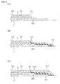
- the rubber ribbon 20 is formed by the nonconductive rubber 21 as shown in FIG. 5(A) , however, is partly provided with a conductive rubber 22 as shown in FIG. 5(B) as occasion demands. At a time of winding, a lower side in FIG. 5 comes to an inner peripheral side which faces the rotation support body 31.
- an inner peripheral side surface of the nonconductive rubber 21 is covered with the conductive rubber 22.
- a cross section of the rubber ribbon 20 is not limited to a triangular shape, but may also be formed in other shapes such as an oval shape, a rectangular shape and the like.
- the forming and the winding of the rubber ribbon 20 can be carried out by using an equipment as exemplified in FIG. 6 .
- This equipment is provided with a rubber ribbon supply apparatus 30 which can form a double-layered rubber ribbon 20 by co-extruding two kinds of rubbers; a rotational support body 31 around which the rubber ribbon 20 supplied from the rubber ribbon supply apparatus 30 is wound; and a control apparatus 32 which carries out an actuation control of the rubber ribbon supply apparatus 30 and the rotational support body 31.
- the rotational support body 31 is structured such that it can rotate in a direction R around an axis 31a and move in an axial direction.
- An extruding machine 33 is provided with a hopper 33a, a screw 33b, a barrel 33c, a drive apparatus 33d of the screw 33b, and a head portion 33e having a gear pump built-in.
- an extruding machine 34 is provided with a hopper 34a, a screw 34b, a barrel 34c, a drive apparatus 34d and a head portion 34e.
- a rubber combining portion 35 additionally provided with a die 36 is provided in leading ends of a pair of extruding machines 33 and 34.
- the respective rubbers are fed out forward while being mixed by the screws 33b and 34b, passed by the head portion 33e and 34e, combined in a predetermined shape at the rubber combining portion 35, and extruded as the double-layered rubber ribbon 20 from a discharge port 36a.
- the formed rubber ribbon 20 is fed out forward by a roll 37, and is wound around the rotational support body 31 while being pressed by a roller 38.
- the rubber ribbon 20 formed as a single layer of the nonconductive rubber 21 can be obtained as shown in FIG. 5(A) .
- the actuation of the gear pump within the head portion 34e and the screw 34b as mentioned above is controlled by the control apparatus 32, and it is possible to freely carry out a switching between the single layer and the double layer of the rubber ribbon.
- the conductive rubber 22 is partly provided in the rubber ribbon 20 in the course of winding, and the conductive portion 13 is formed by the conductive rubber 22.
- the conductive portion 13 extends to the inner side in the tire radial direction from the position on the ground-contacting surface which is separated from the tire equator C to the left side at the distance which is equal to or more than 10 % of the ground-contacting width so as to reach the outer peripheral surface of the base portion 11, and extends to the left side between the cap portion 12 and the base portion 11.
- a second cap portion 12R coming to a right portion of the cap portion 12 is formed in an outer peripheral surface in a right side of the base portion 11. With this configuration, the cap portion 12 is finished, and the tread rubber 10 shown in FIG. 2 is formed.
- the second cap portion 12R is formed by spirally winding the second rubber ribbon constructed by the nonconductive rubber along the tire circumferential direction while utilizing the ribbon winding construction method.
- the second rubber ribbon is formed by the nonconductive rubber, and is provided partly with the conductive rubber as occasion demands, in the same manner as the first rubber ribbon 20.
- the rubber ribbon 20 fed from the rubber ribbon feeding apparatus 30 is thereafter used as the second rubber ribbon, whereby the second cap portion 12R is formed.
- the conductive rubber 22 is partly provided in the rubber ribbon 20 in the course of winding, and the conductive portion 14 is formed by the conductive rubber 22.
- the conductive portion 14 extends to the inner side in the tire radial direction from the position on the ground-contacting surface which is separated from the tire equator C to the right side at the distance which is equal to or more than 10 % of the ground-contacting width so as to reach the outer peripheral surface of the base portion 11, and extends to the right side between the cap portion 12 and the base portion 11.
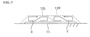
- FIG. 7 conceptually shows an example of a moving route of a winding position of the rubber ribbon 20, in the forming step of the tread rubber shown in FIG. 4 .
- the first rubber ribbon is wound along a route X formed as a transversely figure of 8 shape, in the stage of forming the first cap portion 12L
- the second rubber ribbon is wound along a route Y formed as a transversely figure of 8 shape which is inverted to the route X, in the stage of forming the second cap portion 12R.
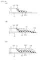
- the first rubber ribbon 20 is wound as shown in FIG. 8 , in the stage of forming the first cap portion 12L.
- the winding position of the rubber ribbon 20 moves to a right side from a start point SL1 which is separated from the tire equator C to a left side, next turns back to the left side so as to pass through the start point SL1, next passes through an end portion in the left side of the base portion 11, and thereafter turns back to the right side so as to reach an end point FL1.
- the conductive rubber 22 is provided in the rubber ribbon 20 as shown in FIG. 5(B) , in a section from a position P1 which is after turning back to the left side and before passing through the start point SL1, to a position P2 which passes through the left end portion of the base portion 11.
- the conductive rubber 22 constructs the conductive portion 13 which extends to an inner side in a tire radial direction from a position on the ground-contacting surface which is separated from the tire equator C to the left side at a distance equal to or more than 10 % of the ground-contacting width, so as to reach the outer peripheral surface of the base portion 11, and extends to the left side between the cap portion 12 and the base portion 11.
- the second rubber ribbon 20 is wound as shown in FIG. 9 , in the stage of forming the second cap portion 12R.
- the winding position of the rubber ribbon 20 moves to a left side from a start point SR1 which is separated from the tire equator C to a right side, next turns back to the right side so as to pass through the start point SR1, next passes through an end portion in the right side of the base portion 11, and thereafter turns back to the left side so as to reach an end point FR1.
- the conductive rubber 22 is provided in the rubber ribbon 20 as shown in FIG. 5(B) , in a section from a position P3 which is after turning back to the right side and before passing through the start point SR1, to a position P4 which passes through the right end portion of the base portion 11.
- the conductive rubber 22 constructs the conductive portion 14 which extends to an inner side in a tire radial direction from a position on the ground-contacting surface which is separated from the tire equator C to the right side at a distance equal to or more than 10 % of the ground-contacting width, so as to reach the outer peripheral surface of the base portion 11, and extends to the right side between the cap portion 12 and the base portion 11.
- the rubber ribbon 20 provided with the conductive rubber 22 is wound in such a manner that the end portion of the conductive rubber 22 comes into contact with an abdominal part of the conductive rubber 22 of the adjacent rubber ribbon 20.
- the conductive portions 13 and 14 have the portions shown in FIG. 4 , and additionally a plurality of branch-shaped portions which are branched to the ground-contacting surface side from the portions and terminate halfway, however, an illustration thereof is omitted.
- the conductive portions 13 and 14 are not limited to such a structure that is provided with the branch-shaped portions mentioned above.
- the end portion in the right side of the first cap portion 12L is tapered so as to form a slant surface, in the stage of forming the first cap portion 12L.
- the rubber ribbon 20 is wound around the slant surface as shown in FIG. 9(B) , and the end portion in the left side of the second cap portion 12R is formed so as to be overlapped with the end portion in the right side of the first cap portion 12L, in the stage of forming the second cap portion 12R.
- the second cap portion 12R is easily connected to the first cap portion 12L.
- the cap portion 12 is constructed by the first cap portion 12L and the second cap portion 12R in the examples in Figs. 4 and 7 , the cap portion 12 can be formed by winding the rubber ribbon 20 twice, and it is advantageous for improving productivity.
- start points SL1 and SR1 and the end points FL1 and FR1 for winding the rubber ribbon are set so as to be spaced at the distance which is at least 10 % of the ground-contacting width from the tire equator, it is possible to prevent an increase of RRO so as to improve the uniformity.
- the belt layer 6 and the belt reinforcing layer 8 are arranged in the inner periphery of the formed tread rubber 10.
- the step proceeds to a forming step of a green tire, whereby the green tire is formed by mounting the tread rubber 10 on the outer peripheral surface of the carcass layer 7 which is formed as the toroidal shape, and combining with the other tire constructing members.
- the step proceeds to a curing step of the green tire, and the pneumatic tire T shown in FIG. 1 is manufactured by applying a curing process to the green tire.
- the step of FIG. 10 includes a stage of forming the third cap portion 12C coming to a center portion in the tire width direction of the cap portion 12, after the stage of forming the base portion 11, as shown in FIG. 10(A) .
- the third cap portion 12C is formed by a nonconductive rubber, and may utilize any of the extrusion forming method and the ribbon winding construction method.
- FIG. 10(B) shows a stage of forming the first cap portion 12L which comes to the left portion of the cap portion 12.
- the conductive portion 13 is formed by the conductive rubber 22 which is provided in the rubber ribbon 20 in the course of winding.
- FIG. 10(C) shows a stage of forming the second cap portion 12R which comes to the right portion of the cap portion 12.
- the conductive portion 14 is formed by the conductive rubber 22 which is provided in the rubber ribbon 20 in the course of winding.
- FIG. 11 conceptually shows an example of a moving route of a winding position of the rubber ribbon 20, in the forming step of the tread rubber shown in FIG. 10 .
- the first rubber ribbon is wound along a route X' formed as a transversely figure of 8 shape, in the stage of forming the first cap portion 12L
- the second rubber ribbon is wound along a route Y' formed as a transversely figure of 8 shape which is inverted to the route X', in the stage of forming the second cap portion 12R.
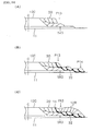
- the first rubber ribbon 20 is wound as shown in FIG. 12 , in the stage of forming the first cap portion 12L.
- the winding position of the rubber ribbon 20 moves to a right side from a start point SL2 which is separated from the tire equator C to a left side, next turns back to the left side so as to pass through the start point SL2, next passes through an end portion in the left side of the base portion 11, and thereafter turns back to the right side so as to reach an end point FL2.
- the conductive rubber 22 is provided in the rubber ribbon 20 in a section from the start point SL2 to a position P5 which turns back to the left side, and a section from a position P6 which comes to just after passing through the start point SL2 to a position P7 which passes through the end portion in the left side of the base portion 11.
- the conductive rubber 22 constructs the conductive portion 13 which extends to an inner side in a tire radial direction from a position on the ground-contacting surface which is separated from the tire equator C to the left side at a distance equal to or more than 10 % of the ground-contacting width, so as to reach the outer peripheral surface of the base portion 11, and extends to the left side between the cap portion 12 and the base portion 11.
- the second rubber ribbon 20 is wound as shown in FIG. 13 , in the stage of forming the second cap portion 12R.
- the winding position of the rubber ribbon 20 moves to a left side from a start point SR2 which is separated from the tire equator C to a right side, next turns back to the right side so as to pass through the start point SR2, next passes through an end portion in the right side of the base portion 11, and thereafter turns back to the left side so as to reach an end point FR2.
- the conductive rubber 22 is provided in the rubber ribbon 20 in a section from the start point SR2 to a position P8 which turns back to the right side, and a section from a position P9 which comes to just after passing through the start point SR2 to a position P10 which passes through the end portion in the right side of the base portion 11.
- the conductive rubber 22 constructs the conductive portion 14 which extends to an inner side in a tire radial direction from a position on the ground-contacting surface which is separated from the tire equator C to the right side at a distance equal to or more than 10 % of the ground-contacting width, so as to reach the outer peripheral surface of the base portion 11, and extends to the right side between the cap portion 12 and the base portion 11.
- the end portions at the both sides of the third cap portion 12C are tapered so as to form a slant surface, in the stage of forming third cap portion 12C.
- the rubber ribbon 20 is wound around the slant surface as shown in FIG. 12(A) , and the end portion in the right side of the first cap portion 12L is formed so as to be overlapped with the end portion in the left side of the third cap portion 12C, in the stage of forming the first cap portion 12L.
- the rubber ribbon 20 is wound around the slant surface as shown in FIG. 13(A) , and the end portion in the left side of the second cap portion 12R is formed so as to be overlapped with the end portion in the right side of the third cap portion 12C, in the stage of forming the second cap portion 12R.
- the step in FIG. 14 includes a stage of forming the third cap portion 12C which comes to the center portion in the tire width direction of the cap portion 12 after the stage of forming the base portion 11, in the same manner as the step in FIG. 10 .
- the rubber ribbon 20 is wound in accordance with the same procedure as the step in FIG. 4 .
- FIG. 14(A) shows a stage of forming a third cap portion 12C
- FIG. 14(B) shows a stage of forming a first cap portion 12L
- FIG. 14(C) shows a stage of forming a second cap portion 12R.
- the conductive portions 13 and 14 are formed by the conductive rubber 22 which is provided in the rubber ribbon 20 in the course of winding respectively. A moving route of a winding position of the rubber ribbon 20 is exemplified in FIG. 11 .
- the first rubber ribbon 20 is wound as shown in FIG. 15 , in the stage of forming the first cap portion 12L.
- the winding position of the rubber ribbon 20 moves to a right side from a start point SL3 which is separated from the tire equator C to a left side, next turns back to the left side so as to pass through the start point SL3, next passes through an end portion in the left side of the base portion 11, and thereafter turns back to the right side so as to reach an end point FL3.
- the conductive rubber 22 is provided in the rubber ribbon 20 in a section from a position P11 which is after turning back to a left side and before passing through the start point SL3, to a position P12 which passes through an end portion on the left side of the base portion 11, thereby constructing the conductive portion 13.
- the second rubber ribbon 20 is wound as shown in FIG. 16 , in the stage of forming the second cap portion 12R.
- the winding position of the rubber ribbon 20 moves to a left side from a start point SR3 which is separated from the tire equator C to a right side, next turns back to the right side so as to pass through the start point SR3, next passes through an end portion on the right side of the base portion 11, and thereafter turns back to the left side so as to reach an end point FR3.
- the conductive rubber 22 is provided in the rubber ribbon 20 in a section from a position P13 which is after turning back to a right side and before passing through the start point SR3, to a position P14 which passes through the end portion on a right side of the base portion 11, thereby constructing the conductive portion 14.
- both end portions in the tire width direction of the third cap portion 12C are formed as a tapered shape.
- an end portion on a right side of the first cap portion 12L is overlapped with an end portion on a left side of the third cap portion 12C
- an end portion on a left side of the second cap portion 12R is overlapped with an end portion on a right side of the third cap portion 12C.
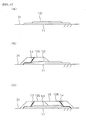
- a stage of forming an inner cap 12i which is narrower than the base portion 11 by a non-conductive rubber in the center portion in the tire width direction of the outer peripheral surface of the base portion 11 is included after the stage of forming the base portion 11.
- the formation of the inner cap 12i may utilize any of the extrusion forming method and the ribbon winding construction method.
- the inner cap 12i is arranged in the center area including the tire equator, and the rate of the width of the inner cap 12i with respect to the tread width is, for example, between 20 % and 80 %, and preferably between 30 % and 70 %.
- the inner cap 12i is formed thinner than the first cap portion 12L and the second cap portion 12R, and is formed such a shape that the thickness of the end portion is reduced little by little.
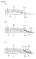
- FIG. 17(A) shows a stage of forming the inner cap 12i
- FIG. 17(B) shows a stage of forming the first cap portion 12L
- FIG. 17(C) shows a stage of forming the second cap portion 12R.
- the conductive portions 13 and 14 are formed by the conductive rubber 22 which is provided in the rubber ribbon 20 in the course of winding respectively.
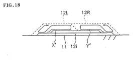
- a moving route of the winding position of the rubber ribbon 20 is exemplified in FIG. 18 .
- the first rubber ribbon is wound along a route X" formed as a transversely figure of 8 shape, and the second rubber ribbon is wound along a route Y" formed as a transversely figure which is opposed thereto.
- the first rubber ribbon 20 is wound as shown in FIG. 19 , in the stage of forming the first cap portion 12L.
- the winding position of the rubber ribbon 20 moves to a right side from a start point SL4 which is separated from the tire equator C to a left side, next turns back to the left side so as to pass through the start point SL4, next passes through an end portion in a left side of the base portion 11, and thereafter turns back to a right side so as to reach an end point FL4.
- the conductive rubber 22 is provided in the rubber ribbon 20 in a section from a position P15 which is after turning back to the left side and before passing through the start point SL4, to a position P16 which passes through the end portion in the left side of the base portion 11, thereby constructing the conductive portion 13.
- the second rubber ribbon 20 is wound as shown in FIG. 20 .
- the winding position of the rubber ribbon 20 moves to a left side from a start point SR4 which is separated from the tire equator C to a right side, next turns back to the right side so as to pass through the start point SR4, next passes through an end portion in a right side of the base portion 11, and thereafter turns back to a left side so as to reach an end point FR4.
- the conductive rubber 22 is provided in the rubber ribbon 20 in a section from a position P17 which is after turning back to the right side and before passing through the start point SR4, to a position P18 which passes through the end portion at the right side of the base portion 11, thereby constructing the conductive portion 14.
- Figs. 17 and 18 there is shown an example in which the end portion of the second cap portion 12R is formed so as to overlap the end portion of the first cap portion 12L, however, the third cap portion as mentioned above may be formed after forming the inner cap 12i.
- the conductive portions 13 and 14 can be formed in accordance with a procedure shown in Figs. 12 and 13 , or a procedure shown in Figs. 15 and 16 .
- first cap portion in accordance with a procedure in FIG. 12
- second cap portion in accordance with a procedure in FIG. 16 .
- An electric resistance value was measured by applying a predetermined load to the tire installed to the rim, and applying an applied voltage (500 V) to a metal plate with which the tire grounds from the shaft supporting the rim.
- LFV lateral force variation
- a result of a Comparative Example 1 is set to 100 so as to be indexed, and the greater numerical value indicates a more excellent uniformity.
- a rolling resistance was measured by a rolling resistance tester, and was evaluated based on an inverse number thereof.
- a Comparative Example 1 is set to 100 and a result is evaluated with indices, the more the numeric value is the less the rolling resistance and the more excellent.
- the distances D13 and D14 are set as shown in Table 1, and Comparative Examples 1 to 3 and Examples 1 to 5 are set.
- the first conductive portion is not provided in the Comparative Example 1 and the Comparative Example 3.
- the tread pattern of each of the examples is a symmetrical block pattern, however, only in the Example 4, a region in a side in which the second conductive portion is provided is formed as a rib pattern. Accordingly, in the Example 4, the positions of the circumferential main grooves are identical between the right and left sides, however, a groove area of a region in a side in which the first conductive portion is provided is larger than a groove area of a region in a side in which the second conductive portion is provided.
- the Example 5 is formed in accordance with the third aspect mentioned above.
Landscapes
- Engineering & Computer Science (AREA)
- Mechanical Engineering (AREA)
- Tires In General (AREA)
- Tyre Moulding (AREA)
Claims (12)
- Luftreifen, der Folgendes aufweist:- ein Paar Wulstbereiche (1);- Seitenwandbereiche (2), die sich von jedem der Wulstbereiche (1) jeweils in Reifenradialrichtung nach außen erstrecken;- einen Laufflächenbereich (3), der mit einem in Reifenradialrichtung äußeren Ende von jedem der Seitenwandbereiche (2) verbunden ist;- eine ringförmige Karkassenlage (7), die zwischen dem Paar von Wulstbereichen (1) vorgesehen ist;- ein Seitenwandgummimaterial (9), das an einer Außenseite der Karkassenlage in dem Seitenwandbereich (2) vorgesehen ist; und- ein Laufflächengummimaterial (10), das an einer Außenseite der Karkassenlage (7) in dem Laufflächenbereich (3) vorgesehen ist;wobei das Laufflächengummimaterial (10) einen Abdeckbereich (12) aufweist, der aus einem nicht-leitfähigen Gummimaterial (21) gebildet ist und eine Bodenkontaktfläche bildet, und einen Basisbereich (11) aufweist, der aus dem nicht-leitfähigen Gummimaterial (21) gebildet ist und in Reifenradialrichtung innenseitig von dem Abdeckbereich (12) vorgesehen ist,
dadurch gekennzeichnet,
dass ein Paar leitfähige Bereiche (13, 14), die aus einem leitfähigen Gummimaterial gebildet sind, an der Bodenkontaktfläche freiliegen, und- wobei das Paar der leitfähigen Bereiche (13, 14) Folgendes aufweist:(a) einen ersten leitfähigen Bereich (13), der sich von der Bodenkontaktfläche in Reifenradialrichtung derart nach innen erstreckt, dass er eine Außenumfangsfläche des Basisbereichs (11) erreicht, sich zwischen dem Abdeckbereich (12) und dem Basisbereich (11) in Reifenbreitenrichtung zur einen Seite erstreckt, mit einem Abdeckgummimaterial der Karkassenlage (7) oder dem Seitenwandgummimaterial (9) verbunden ist und an einer freiliegenden Position an der Bodenkontaktfläche von einem Reifenäquator (C) zur einen Seite in Reifenbreitenrichtung über eine Distanz getrennt ist, die gleich oder mehr als 10 % einer Bodenkontaktbreite beträgt; und(b) einen zweiten leitfähigen Bereich (14), der sich von der Bodenkontaktfläche in Reifenradialrichtung derart nach innen erstreckt, dass er eine Außenumfangsfläche des Basisbereichs (11) erreicht, sich zwischen dem Abdeckbereich (12) und dem Basisbereich (11) in Reifenbreitenrichtung zur anderen Seite erstreckt, mit dem Abdeckgummimaterial der Karkassenlage (7) oder dem Seitenwandgummimaterial (9) verbunden ist und an einer freiliegenden Position an der Bodenkontaktfläche von dem Reifenäquator (C) zur anderen Seite in Reifenbreitenrichtung über eine Distanz getrennt ist, die gleich oder mehr als 10 % der Bodenkontaktbreite beträgt. - Luftreifen nach Anspruch 1,
wobei eine umfangsmäßige Hauptnut (15) in einer Oberfläche des Laufflächengummimaterials (10) unter Umgehung eines Bereichs gebildet ist, in dem sich der erste leitfähige Bereich (13) und der zweite leitfähige Bereich (14) von der Bodenkontaktfläche in Reifenradialrichtung derart nach innen erstrecken, dass sie eine Außenumfangsfläche des Basisbereichs (11) erreichen. - Luftreifen nach Anspruch 1,
wobei eine Nutfläche einer Region, die auf der Basis des Reifenäquators (C) in Reifenbreitenrichtung auf der einen Seite der Bodenkontaktfläche zu liegen kommt, größer ist als eine Nutfläche einer Region, die in Reifenbreitenrichtung auf der anderen Seite zu liegen kommt, und wobei eine Distanz von der freiliegenden Position an der Bodenkontaktfläche des ersten leitfähigen Bereichs (13) bis zum Reifenäquator (C) größer ist als eine Distanz von der freiliegenden Position an der Bodenkontaktfläche des zweiten leitfähigen Bereichs (14) bis zum Reifenäquator (C). - Verfahren zum Herstellen eines Luftreifens, das einen Schritt zum Bilden eines Laufflächengummis (10) beinhaltet, das in Reifenradialrichtung innenseitig von einem Abdeckbereich (12), der eine Bodenkontaktfläche bildet, mit einem Basisbereich (11) versehen wird,
wobei der Schritt zum Bilden des Laufflächengummis Folgendes aufweist:- eine Stufe zum Bilden des Basisbereichs (11) aus einem nicht-leitfähigen Gummimaterial;- eine Stufe zum Bilden eines ersten Abdeckbereichs (12L), der in Reifenbreitenrichtung an dem einen Seitenbereich des Abdeckbereichs (12) zu liegen kommt, durch spiralförmiges Wickeln eines ersten Gummibandes (20) aus dem nicht-leitfähigen Gummimaterial (21) entlang einer Reifenumfangsrichtung auf eine Außenumfangsfläche auf der in Reifenbreitenrichtung einen Seite des Basisbereichs (11); und- eine Stufe zum Bilden eines zweiten Abdeckbereichs (12R), der in der Reifenbreitenrichtung an dem anderen Seitenbereich des Abdeckbereichs (12) zu liegen kommt, durch spiralförmiges Wickeln eines zweiten Gummibandes (20) aus dem nicht-leitfähigen Gummimaterial (21) entlang der Reifenumfangsrichtung auf eine Außenumfangsfläche auf der in Reifenbreitenrichtung anderen Seite des Basisbereichs (11),- wobei die Stufe zum Bilden des ersten Abdeckbereichs (12L) teilweise ein leitfähiges Gummimaterial (22) in dem ersten Gummiband (20) im Verlauf des Wickelvorgangs absetzt und durch das leitfähige Gummimaterial (22) einen ersten leitfähigen Bereich (13) bildet, der sich von einer Position an der Bodenkontaktfläche, die von dem Reifenäquator (C) in Reifenbreitenrichtung zur einen Seite über eine Distanz getrennt ist, die gleich oder mehr als 10 % einer Bodenkontaktbreite beträgt, in Reifenradialrichtung derart nach innen erstreckt, dass er eine Außenumfangsfläche des Basisbereichs (11) erreicht, und der sich zwischen dem Abdeckbereich (12) und dem Basisbereich (11) in Reifenbreitenrichtung zur einen Seite erstreckt, und- wobei die Stufe zum Bilden des zweiten Abdeckbereichs (12R) teilweise das leitfähige Gummimaterial (22) in dem zweiten Gummiband (20) im Verlauf des Wickelvorgangs absetzt und durch das leitfähige Gummimaterial (22) einen zweiten leitfähigen Bereich (14) bildet, der sich von einer Position an der Bodenkontaktfläche, die von dem Reifenäquator (C) in Reifenbreitenrichtung zur anderen Seite über eine Distanz getrennt ist, die gleich oder mehr als 10 % der Bodenkontaktbreite beträgt, in Reifenradialrichtung derart nach innen erstreckt, dass er die Außenumfangsfläche des Basisbereichs (11) erreicht, und der sich zwischen dem Abdeckbereich (12) und dem Basisbereich (11) in Reifenbreitenrichtung zur anderen Seite erstreckt. - Verfahren nach Anspruch 4,
wobei in der Stufe zum Bilden des ersten Abdeckbereichs (12L) die Wickelposition des ersten Gummibandes (20) von einem Startpunkt, der von dem Reifenäquator (C) zur einen Seite in Reifenbreitenrichtung getrennt ist, zu der in Reifenbreitenrichtung anderen Seite verlagert wird, sodann zur einen Seite in Reifenbreitenrichtung zurückkehrt, um so den Startpunkt zu passieren, als nächstes einen in Reifenbreitenrichtung auf der einen Seite befindlichen Endbereich des Basisbereichs (11) passiert und anschließend zu der anderen Seite in Reifenbreitenrichtung zurückkehrt, um so einen Endpunkt zu erreichen, und wobei das leitfähige Gummimaterial (22) zum Bilden des ersten leitfähigen Bereichs (13) in dem ersten Gummiband (20) in einem Bereich vorgesehen wird, der von einer Position, die nach dem Zurückkehren zur einen Seite in Reifenbreitenrichtung und vor dem Passieren des Startpunkts erreicht wird, bis zu einer Position reicht, an der der in Reifenbreitenrichtung auf der einen Seite befindliche Endbereich des Basisbereichs (11) passiert wird, oder
wobei in der Stufe zum Bilden des zweiten Abdeckbereichs (12R) die Wickelposition des zweiten Gummibandes (20) von einem Startpunkt, der von dem Reifenäquator (C) zur anderen Seite in Reifenbreitenrichtung getrennt ist, zur einen Seite in Reifenbreitenrichtung verlagert wird, sodann zu der anderen Seite in Reifenbreitenrichtung zurückkehrt, um so den Startpunkt zu passieren, als nächstes einen in Reifenbreitenrichtung auf der anderen Seite befindlichen Endbereich des Basisbereichs (11) passiert und danach zu der einen Seite in Reifenbreitenrichtung zurückkehrt, um so einen Endpunkt zu erreichen, und wobei das leitfähige Gummimaterial (22) zum Bilden des zweiten leitfähigen Bereichs (14) in dem zweiten Gummiband (20) in einem Bereich vorgesehen wird, der von einer Position, die nach dem Zurückkehren zur anderen Seite in Reifenbreitenrichtung und vor dem Passieren des Startpunkts erreicht wird, bis zu einer Position reicht, an der der in Reifenbreitenrichtung auf der anderen Seite befindliche Endbereich des Basisbereichs (11) passiert wird. - Verfahren nach Anspruch 5,
wobei der in Reifenbreitenrichtung auf der anderen Seite befindliche Endbereich des ersten Abdeckbereichs (12L) mit einer sich verjüngenden Formgebung in der Stufe zum Bilden des ersten Abdeckbereichs (12L) gebildet wird, und wobei der in der Reifenbreitenrichtung auf der einen Seite befindliche Endbereich des zweiten Abdeckbereichs (12R) in der Stufe zum Bilden des zweiten Abdeckbereichs (12R) derart gebildet wird, dass er mit dem in Reifenbreitenrichtung auf der anderen Seite befindlichen Endbereich des ersten Abdeckbereichs (12L) in überlappender Weise vorgesehen wird. - Verfahren nach Anspruch 5,
wobei der Schritt zum Bilden des Laufflächengummis (10) eine Stufe zum Bilden eines dritten Abdeckbereichs (12C) beinhaltet, der in Reifenbreitenrichtung in einem mittleren Bereich des Abdeckbereichs (12) zu liegen kommt, und wobei der in Reifenbreitenrichtung auf der anderen Seite befindliche Endbereich des ersten Abdeckbereichs (12L) mit dem in Reifenbreitenrichtung auf der einen Seite befindlichen Endbereich des dritten Abdeckbereichs (12C) in überlappender Weise vorgesehen wird und der in der Reifenbreitenrichtung auf der einen Seite befindliche Endbereich des zweiten Abdeckbereichs (12R) mit dem in Reifenbreitenrichtung auf der anderen Seite befindlichen Endbereich des dritten Abdeckbereichs (12C) in überlappender Weise vorgesehen wird. - Verfahren nach Anspruch 4,
wobei der Schritt zum Bilden des Laufflächengummis (10) eine Stufe zum Bilden eines dritten Abdeckbereichs (12C) beinhaltet, der in Reifenbreitenrichtung in einem mittleren Bereich des Abdeckbereichs (12) zu liegen kommt, und wobei in der Stufe zum Bilden des ersten Abdeckbereichs (12L) die Wickelposition des ersten Gummibandes (20) von einem Startpunkt, der von dem Reifenäquator (C) in Reifenbreitenrichtung zur einen Seite getrennt ist, zu der in Reifenbreitenrichtung anderen Seite verlagert wird, sodann zu der einen Seite in Reifenbreitenrichtung zurückkehrt, um so den Startpunkt zu passieren, als nächstes einen in Reifenbreitenrichtung auf der einen Seite befindlichen Endbereich des Basisbereichs (11) passiert und anschließend zu der anderen Seite in Reifenbreitenrichtung zurückkehrt, um so einen Endpunkt erreichen, und wobei das leitfähige Gummimaterial zum Bilden des ersten leitfähigen Bereichs (12L) in dem ersten Gummiband (20) in einem Bereich vorgesehen wird, der von dem Startpunkt bis zu einer Position reicht, an der ein Zurückkehren auf die eine Seite in Reifenbreitenrichtung erfolgt, sowie in einem Bereich vorgesehen wird, der von einer Stelle unmittelbar nach dem Passieren des Startpunkts bis zu einer Position reicht, an der der in Reifenbreitenrichtung auf der einen Seite befindliche Endbereich des Basisbereichs (11) passiert wird, oder
wobei in der Stufe zum Bilden des zweiten Abdeckbereichs (12R) die Wickelposition des zweiten Gummibandes (20) von einem Startpunkt, der von dem Reifenäquator (C) in Reifenbreitenrichtung zur anderen Seite getrennt ist, zu der einen Seite in Reifenbreitenrichtung verlagert wird, sodann zu der anderen Seite in Reifenbreitenrichtung zurückkehrt, um so den Startpunkt zu passieren, als nächstes einen in Reifenbreitenrichtung auf der anderen Seite befindlichen Endbereich des Basisbereichs (11) passiert und danach zu der einen Seite in Reifenbreitenrichtung zurückkehrt, um so einen Endpunkt erreichen, und wobei das leitfähige Gummimaterial zum Bilden des zweiten leitfähigen Bereichs (14) in dem zweiten Gummiband (20) in einem Bereich vorgesehen wird, der von dem Startpunkt bis zu einer Position reicht, an der ein Zurückkehren auf die andere Seite in Reifenbreitenrichtung erfolgt, sowie in einem Bereich vorgesehen wird, der von einer Stelle unmittelbar nach dem Passieren des Startpunkts bis zu einer Position reicht, an der der in Reifenbreitenrichtung auf der anderen Seite befindliche Endbereich des Basisbereichs (11) passiert wird. - Verfahren nach Anspruch 8,
wobei in Reifenbreitenrichtung beide Endbereiche des dritten Abdeckbereichs (12C) mit einer sich verjüngenden Formgebung in der Stufe zum Bilden des dritten Abdeckbereichs (12C) gebildet werden,
wobei der in Reifenbreitenrichtung auf der anderen Seite befindliche Endbereich des ersten Abdeckbereichs (12L) in der Stufe zum Bilden des ersten Abdeckbereichs (12L) derart gebildet wird, dass er mit dem in Reifenbreitenrichtung auf der einen Seite befindlichen Endbereich des dritten Abdeckbereichs (12C) überlappend ausgebildet ist, und
wobei der in Reifenbreitenrichtung auf der einen Seite befindliche Endbereich des zweiten Abdeckbereichs (12R) derart gebildet wird, dass er mit dem in Reifenbreitenrichtung auf der anderen Seite befindlichen Endbereich des dritten Abdeckbereichs (12C) überlappend ausgebildet ist. - Verfahren nach Anspruch 4,
wobei der Schritt zum Bilden des Laufflächengummis (10) eine Stufe zum Bilden einer inneren Abdeckung (12i), die schmaler ist als der Basisbereich (11), in einem in Reifenbreitenrichtung zentralen Bereich einer Außenumfangsfläche des Basisbereichs (11) aus einem nicht-leitfähigen Gummimaterial beinhaltet, und wobei der Abdeckbereich (12) derart gebildet wird, dass er die innere Abdeckung (12i) bedeckt. - Verfahren nach Anspruch 5,
wobei der Schritt zum Bilden des Laufflächengummis (10) eine Stufe zum Bilden einer inneren Abdeckung (12i), die schmaler ist als der Basisbereich (11), in einem in Reifenbreitenrichtung zentralen Bereich einer Außenumfangsfläche des Basisbereichs (11) aus einem nicht-leitfähigen Gummimaterial beinhaltet, und wobei der Abdeckbereich (12) derart gebildet wird, dass er die innere Abdeckung (12i) bedeckt. - Verfahren nach Anspruch 8,
wobei der Schritt zum Bilden des Laufflächengummis (10) eine Stufe zum Bilden einer inneren Abdeckung (12i), die schmaler ist als der Basisbereich (11), in einem in Reifenbreitenrichtung zentralen Bereich einer Außenumfangsfläche des Basisbereichs (11) aus einem nicht-leitfähigen Gummimaterial beinhaltet, und wobei der Abdeckbereich (12) derart gebildet wird, dass er die innere Abdeckung (12i) bedeckt.
Applications Claiming Priority (2)
| Application Number | Priority Date | Filing Date | Title |
|---|---|---|---|
| JP2011206346 | 2011-09-21 | ||
| JP2012006361A JP5456074B2 (ja) | 2011-09-21 | 2012-01-16 | 空気入りタイヤの製造方法 |
Publications (2)
| Publication Number | Publication Date |
|---|---|
| EP2572902A1 EP2572902A1 (de) | 2013-03-27 |
| EP2572902B1 true EP2572902B1 (de) | 2014-11-05 |
Family
ID=46582619
Family Applications (1)
| Application Number | Title | Priority Date | Filing Date |
|---|---|---|---|
| EP12178010.0A Not-in-force EP2572902B1 (de) | 2011-09-21 | 2012-07-26 | Luftreifen und Herstellungsverfahren dafür |
Country Status (4)
| Country | Link |
|---|---|
| US (2) | US9327559B2 (de) |
| EP (1) | EP2572902B1 (de) |
| JP (1) | JP5456074B2 (de) |
| CN (1) | CN103009931B (de) |
Families Citing this family (22)
| Publication number | Priority date | Publication date | Assignee | Title |
|---|---|---|---|---|
| JP5456074B2 (ja) * | 2011-09-21 | 2014-03-26 | 東洋ゴム工業株式会社 | 空気入りタイヤの製造方法 |
| JP6061577B2 (ja) * | 2011-12-19 | 2017-01-18 | 東洋ゴム工業株式会社 | 空気入りタイヤ及びその製造方法 |
| JP5363600B2 (ja) * | 2012-02-21 | 2013-12-11 | 住友ゴム工業株式会社 | 空気入りタイヤ |
| US20140224392A1 (en) * | 2013-02-14 | 2014-08-14 | Ling Du | Tire with electrically non-conductive rubber tread with electrically conductive, carbon nanotube containing rubber strip extending through the tread to its running surface |
| JP6077407B2 (ja) * | 2013-07-03 | 2017-02-08 | 東洋ゴム工業株式会社 | 空気入りタイヤ |
| JP6147650B2 (ja) * | 2013-11-22 | 2017-06-14 | 住友ゴム工業株式会社 | 空気入りタイヤの製造方法 |
| CN105829146A (zh) | 2013-12-19 | 2016-08-03 | 普利司通美国轮胎运营有限责任公司 | 具有静电荷耗散元件的轮胎 |
| JP6075285B2 (ja) * | 2013-12-26 | 2017-02-08 | 横浜ゴム株式会社 | 空気入りタイヤ |
| JP6329434B2 (ja) * | 2014-05-20 | 2018-05-23 | 住友ゴム工業株式会社 | 空気入りタイヤ |
| JP6289309B2 (ja) * | 2014-08-26 | 2018-03-07 | 東洋ゴム工業株式会社 | 空気入りタイヤ |
| JP6759703B2 (ja) * | 2016-05-19 | 2020-09-23 | 住友ゴム工業株式会社 | 空気入りタイヤ及びその製造方法 |
| JP6735175B2 (ja) * | 2016-07-29 | 2020-08-05 | Toyo Tire株式会社 | 空気入りタイヤ |
| DE102016217970A1 (de) * | 2016-09-20 | 2018-03-22 | Continental Reifen Deutschland Gmbh | Fahrzeugluftreifen |
| JP6897189B2 (ja) * | 2017-03-16 | 2021-06-30 | 住友ゴム工業株式会社 | 空気入りタイヤ及びその製造方法 |
| FR3065913B1 (fr) * | 2017-05-02 | 2019-06-07 | Compagnie Generale Des Etablissements Michelin | Flanc de pneumatique pour vehicule lourd de type genie civil |
| FR3065914B1 (fr) * | 2017-05-02 | 2019-06-07 | Compagnie Generale Des Etablissements Michelin | Architecture de sommet electro-conductrice d''un pneumatique pour vehicule lourd de type genie civil |
| JP6930262B2 (ja) * | 2017-07-18 | 2021-09-01 | 横浜ゴム株式会社 | 空気入りタイヤ及び空気入りタイヤの製造方法 |
| WO2020013210A1 (ja) * | 2018-07-11 | 2020-01-16 | 住友ゴム工業株式会社 | 重荷重用空気入りタイヤ及びその製造方法 |
| WO2020072245A1 (en) | 2018-10-02 | 2020-04-09 | Bridgestone Americas Tire Operations, Llc | Tire having a conductive path in a sidewall |
| JP7207240B2 (ja) * | 2019-09-03 | 2023-01-18 | 横浜ゴム株式会社 | 空気入りタイヤ及びグリーンタイヤの製造方法 |
| JP7494482B2 (ja) | 2020-02-18 | 2024-06-04 | 住友ゴム工業株式会社 | トレッドゴム形成方法及びトレッドゴム形成装置 |
| JP7466430B2 (ja) * | 2020-11-11 | 2024-04-12 | 住友ゴム工業株式会社 | エラストマー組成物及びタイヤ |
Family Cites Families (23)
| Publication number | Priority date | Publication date | Assignee | Title |
|---|---|---|---|---|
| JPH02303905A (ja) * | 1989-05-17 | 1990-12-17 | Toyo Tire & Rubber Co Ltd | 空気入りタイヤ |
| IT1250030B (it) * | 1991-10-31 | 1995-03-30 | Firestone Int Dev Spa | Procedimento per la realizzazione di pneumatici. |
| JPH06239110A (ja) * | 1993-02-19 | 1994-08-30 | Ohtsu Tire & Rubber Co Ltd :The | 自動車用空気入りタイヤ |
| DE4447823B4 (de) * | 1994-12-21 | 2007-07-26 | Dunlop Gmbh | Fahrzeugreifen und Verfahren zu seiner Herstellung |
| JP5013636B2 (ja) * | 2000-05-24 | 2012-08-29 | 株式会社ブリヂストン | タイヤ構成部材の成形方法 |
| JP2002347135A (ja) * | 2001-05-29 | 2002-12-04 | Bridgestone Corp | タイヤの製造方法 |
| JP4039895B2 (ja) * | 2002-06-24 | 2008-01-30 | 横浜ゴム株式会社 | タイヤトレッド構成部材の成形方法及び空気入りタイヤ |
| JP4547136B2 (ja) * | 2003-07-16 | 2010-09-22 | 株式会社ブリヂストン | タイヤおよびタイヤの製造方法 |
| CN101374680B (zh) * | 2006-02-20 | 2010-07-07 | 东洋橡胶工业株式会社 | 充气轮胎以及充气轮胎的制造方法 |
| JP4908905B2 (ja) * | 2006-04-24 | 2012-04-04 | 東洋ゴム工業株式会社 | 空気入りタイヤ |
| JP4750853B2 (ja) | 2006-08-31 | 2011-08-17 | 東洋ゴム工業株式会社 | 空気入りタイヤの製造方法 |
| JP5116293B2 (ja) * | 2006-11-24 | 2013-01-09 | 株式会社ブリヂストン | タイヤの製造方法 |
| JP2009023152A (ja) * | 2007-07-18 | 2009-02-05 | Toyo Tire & Rubber Co Ltd | 空気入りタイヤの製造方法 |
| JP2009113398A (ja) * | 2007-11-08 | 2009-05-28 | Sumitomo Rubber Ind Ltd | タイヤ製造方法 |
| US20100258227A1 (en) * | 2007-11-21 | 2010-10-14 | Takeshi Kuroki | Pneumatic tire and production method therefor |
| JP4392444B2 (ja) | 2007-11-21 | 2010-01-06 | 住友ゴム工業株式会社 | 空気入りタイヤ及びその製造方法 |
| JP4501119B2 (ja) * | 2008-01-08 | 2010-07-14 | 東洋ゴム工業株式会社 | 空気入りタイヤ及びその製造方法 |
| JP4575979B2 (ja) | 2008-11-11 | 2010-11-04 | 住友ゴム工業株式会社 | 空気入りタイヤ及びその製造方法 |
| JP5266132B2 (ja) | 2009-05-15 | 2013-08-21 | 住友ゴム工業株式会社 | 空気入りタイヤ |
| JP5091938B2 (ja) * | 2009-12-15 | 2012-12-05 | 住友ゴム工業株式会社 | 空気入りタイヤ |
| JP5624369B2 (ja) * | 2010-06-02 | 2014-11-12 | 住友ゴム工業株式会社 | 空気入りタイヤ及びその製造方法 |
| JP4783479B1 (ja) * | 2011-02-10 | 2011-09-28 | 東洋ゴム工業株式会社 | 空気入りタイヤ |
| JP5456074B2 (ja) * | 2011-09-21 | 2014-03-26 | 東洋ゴム工業株式会社 | 空気入りタイヤの製造方法 |
-
2012
- 2012-01-16 JP JP2012006361A patent/JP5456074B2/ja active Active
- 2012-02-16 US US13/397,854 patent/US9327559B2/en active Active
- 2012-06-19 CN CN201210208839.5A patent/CN103009931B/zh active Active
- 2012-07-26 EP EP12178010.0A patent/EP2572902B1/de not_active Not-in-force
-
2016
- 2016-03-28 US US15/082,636 patent/US10086659B2/en active Active
Also Published As
| Publication number | Publication date |
|---|---|
| US20130068358A1 (en) | 2013-03-21 |
| JP2013079049A (ja) | 2013-05-02 |
| US9327559B2 (en) | 2016-05-03 |
| US10086659B2 (en) | 2018-10-02 |
| US20160280016A1 (en) | 2016-09-29 |
| CN103009931B (zh) | 2016-01-20 |
| JP5456074B2 (ja) | 2014-03-26 |
| EP2572902A1 (de) | 2013-03-27 |
| CN103009931A (zh) | 2013-04-03 |
Similar Documents
| Publication | Publication Date | Title |
|---|---|---|
| EP2572902B1 (de) | Luftreifen und Herstellungsverfahren dafür | |
| US9579860B2 (en) | Manufacturing method of pneumatic tire | |
| EP2394826B1 (de) | Luftreifen | |
| US9744814B2 (en) | Pneumatic tire and manufacturing method of pneumatic tire | |
| EP2487051B1 (de) | Luftreifen | |
| US8550132B2 (en) | Pneumatic tire and manufacturing method of the same | |
| US8167014B2 (en) | Manufacturing method of pneumatic tire and pneumatic tire | |
| US8171966B2 (en) | Pneumatic tire and method for manufacturing the same | |
| US8167015B2 (en) | Method of manufacturing pneumatic tire and manufacturing pneumatic tire | |
| US20080216929A1 (en) | Manufacturing method of pneumatic tire and pneumatic tire | |
| US9028630B2 (en) | Pneumatic tire and manufacturing method of pneumatic tire | |
| JP2012183656A (ja) | 空気入りタイヤの製造方法及び空気入りタイヤ | |
| JP5611861B2 (ja) | 空気入りタイヤの製造方法及び空気入りタイヤ | |
| EP2837511A1 (de) | Luftreifen | |
| JP5970179B2 (ja) | 空気入りタイヤの製造方法及び空気入りタイヤ | |
| JP5508248B2 (ja) | 空気入りタイヤ及びその製造方法 |
Legal Events
| Date | Code | Title | Description |
|---|---|---|---|
| PUAI | Public reference made under article 153(3) epc to a published international application that has entered the european phase |
Free format text: ORIGINAL CODE: 0009012 |
|
| AK | Designated contracting states |
Kind code of ref document: A1 Designated state(s): AL AT BE BG CH CY CZ DE DK EE ES FI FR GB GR HR HU IE IS IT LI LT LU LV MC MK MT NL NO PL PT RO RS SE SI SK SM TR |
|
| AX | Request for extension of the european patent |
Extension state: BA ME |
|
| 17P | Request for examination filed |
Effective date: 20130304 |
|
| RIC1 | Information provided on ipc code assigned before grant |
Ipc: B60C 19/08 20060101AFI20140117BHEP Ipc: B29D 30/52 20060101ALI20140117BHEP Ipc: B60C 11/00 20060101ALI20140117BHEP Ipc: B29D 30/60 20060101ALI20140117BHEP |
|
| GRAP | Despatch of communication of intention to grant a patent |
Free format text: ORIGINAL CODE: EPIDOSNIGR1 |
|
| INTG | Intention to grant announced |
Effective date: 20140513 |
|
| RAP1 | Party data changed (applicant data changed or rights of an application transferred) |
Owner name: TOYO TIRE & RUBBER CO., LTD. |
|
| GRAS | Grant fee paid |
Free format text: ORIGINAL CODE: EPIDOSNIGR3 |
|
| GRAA | (expected) grant |
Free format text: ORIGINAL CODE: 0009210 |
|
| AK | Designated contracting states |
Kind code of ref document: B1 Designated state(s): AL AT BE BG CH CY CZ DE DK EE ES FI FR GB GR HR HU IE IS IT LI LT LU LV MC MK MT NL NO PL PT RO RS SE SI SK SM TR |
|
| REG | Reference to a national code |
Ref country code: GB Ref legal event code: FG4D |
|
| REG | Reference to a national code |
Ref country code: CH Ref legal event code: EP |
|
| REG | Reference to a national code |
Ref country code: AT Ref legal event code: REF Ref document number: 694403 Country of ref document: AT Kind code of ref document: T Effective date: 20141115 |
|
| REG | Reference to a national code |
Ref country code: IE Ref legal event code: FG4D |
|
| REG | Reference to a national code |
Ref country code: DE Ref legal event code: R096 Ref document number: 602012003638 Country of ref document: DE Effective date: 20141224 |
|
| REG | Reference to a national code |
Ref country code: AT Ref legal event code: MK05 Ref document number: 694403 Country of ref document: AT Kind code of ref document: T Effective date: 20141105 |
|
| REG | Reference to a national code |
Ref country code: NL Ref legal event code: VDEP Effective date: 20141105 |
|
| REG | Reference to a national code |
Ref country code: LT Ref legal event code: MG4D |
|
| PG25 | Lapsed in a contracting state [announced via postgrant information from national office to epo] |
Ref country code: NO Free format text: LAPSE BECAUSE OF FAILURE TO SUBMIT A TRANSLATION OF THE DESCRIPTION OR TO PAY THE FEE WITHIN THE PRESCRIBED TIME-LIMIT Effective date: 20150205 Ref country code: NL Free format text: LAPSE BECAUSE OF FAILURE TO SUBMIT A TRANSLATION OF THE DESCRIPTION OR TO PAY THE FEE WITHIN THE PRESCRIBED TIME-LIMIT Effective date: 20141105 Ref country code: FI Free format text: LAPSE BECAUSE OF FAILURE TO SUBMIT A TRANSLATION OF THE DESCRIPTION OR TO PAY THE FEE WITHIN THE PRESCRIBED TIME-LIMIT Effective date: 20141105 Ref country code: LT Free format text: LAPSE BECAUSE OF FAILURE TO SUBMIT A TRANSLATION OF THE DESCRIPTION OR TO PAY THE FEE WITHIN THE PRESCRIBED TIME-LIMIT Effective date: 20141105 Ref country code: IS Free format text: LAPSE BECAUSE OF FAILURE TO SUBMIT A TRANSLATION OF THE DESCRIPTION OR TO PAY THE FEE WITHIN THE PRESCRIBED TIME-LIMIT Effective date: 20150305 Ref country code: PT Free format text: LAPSE BECAUSE OF FAILURE TO SUBMIT A TRANSLATION OF THE DESCRIPTION OR TO PAY THE FEE WITHIN THE PRESCRIBED TIME-LIMIT Effective date: 20150305 Ref country code: ES Free format text: LAPSE BECAUSE OF FAILURE TO SUBMIT A TRANSLATION OF THE DESCRIPTION OR TO PAY THE FEE WITHIN THE PRESCRIBED TIME-LIMIT Effective date: 20141105 |
|
| PG25 | Lapsed in a contracting state [announced via postgrant information from national office to epo] |
Ref country code: SE Free format text: LAPSE BECAUSE OF FAILURE TO SUBMIT A TRANSLATION OF THE DESCRIPTION OR TO PAY THE FEE WITHIN THE PRESCRIBED TIME-LIMIT Effective date: 20141105 Ref country code: CY Free format text: LAPSE BECAUSE OF FAILURE TO SUBMIT A TRANSLATION OF THE DESCRIPTION OR TO PAY THE FEE WITHIN THE PRESCRIBED TIME-LIMIT Effective date: 20141105 Ref country code: GR Free format text: LAPSE BECAUSE OF FAILURE TO SUBMIT A TRANSLATION OF THE DESCRIPTION OR TO PAY THE FEE WITHIN THE PRESCRIBED TIME-LIMIT Effective date: 20150206 Ref country code: AT Free format text: LAPSE BECAUSE OF FAILURE TO SUBMIT A TRANSLATION OF THE DESCRIPTION OR TO PAY THE FEE WITHIN THE PRESCRIBED TIME-LIMIT Effective date: 20141105 Ref country code: LV Free format text: LAPSE BECAUSE OF FAILURE TO SUBMIT A TRANSLATION OF THE DESCRIPTION OR TO PAY THE FEE WITHIN THE PRESCRIBED TIME-LIMIT Effective date: 20141105 Ref country code: HR Free format text: LAPSE BECAUSE OF FAILURE TO SUBMIT A TRANSLATION OF THE DESCRIPTION OR TO PAY THE FEE WITHIN THE PRESCRIBED TIME-LIMIT Effective date: 20141105 Ref country code: RS Free format text: LAPSE BECAUSE OF FAILURE TO SUBMIT A TRANSLATION OF THE DESCRIPTION OR TO PAY THE FEE WITHIN THE PRESCRIBED TIME-LIMIT Effective date: 20141105 Ref country code: PL Free format text: LAPSE BECAUSE OF FAILURE TO SUBMIT A TRANSLATION OF THE DESCRIPTION OR TO PAY THE FEE WITHIN THE PRESCRIBED TIME-LIMIT Effective date: 20141105 |
|
| PG25 | Lapsed in a contracting state [announced via postgrant information from national office to epo] |
Ref country code: SK Free format text: LAPSE BECAUSE OF FAILURE TO SUBMIT A TRANSLATION OF THE DESCRIPTION OR TO PAY THE FEE WITHIN THE PRESCRIBED TIME-LIMIT Effective date: 20141105 Ref country code: CZ Free format text: LAPSE BECAUSE OF FAILURE TO SUBMIT A TRANSLATION OF THE DESCRIPTION OR TO PAY THE FEE WITHIN THE PRESCRIBED TIME-LIMIT Effective date: 20141105 Ref country code: DK Free format text: LAPSE BECAUSE OF FAILURE TO SUBMIT A TRANSLATION OF THE DESCRIPTION OR TO PAY THE FEE WITHIN THE PRESCRIBED TIME-LIMIT Effective date: 20141105 Ref country code: EE Free format text: LAPSE BECAUSE OF FAILURE TO SUBMIT A TRANSLATION OF THE DESCRIPTION OR TO PAY THE FEE WITHIN THE PRESCRIBED TIME-LIMIT Effective date: 20141105 |
|
| REG | Reference to a national code |
Ref country code: DE Ref legal event code: R097 Ref document number: 602012003638 Country of ref document: DE |
|
| PLBE | No opposition filed within time limit |
Free format text: ORIGINAL CODE: 0009261 |
|
| STAA | Information on the status of an ep patent application or granted ep patent |
Free format text: STATUS: NO OPPOSITION FILED WITHIN TIME LIMIT |
|
| 26N | No opposition filed |
Effective date: 20150806 |
|
| PG25 | Lapsed in a contracting state [announced via postgrant information from national office to epo] |
Ref country code: IT Free format text: LAPSE BECAUSE OF FAILURE TO SUBMIT A TRANSLATION OF THE DESCRIPTION OR TO PAY THE FEE WITHIN THE PRESCRIBED TIME-LIMIT Effective date: 20141105 |
|
| PG25 | Lapsed in a contracting state [announced via postgrant information from national office to epo] |
Ref country code: MC Free format text: LAPSE BECAUSE OF FAILURE TO SUBMIT A TRANSLATION OF THE DESCRIPTION OR TO PAY THE FEE WITHIN THE PRESCRIBED TIME-LIMIT Effective date: 20141105 Ref country code: SI Free format text: LAPSE BECAUSE OF FAILURE TO SUBMIT A TRANSLATION OF THE DESCRIPTION OR TO PAY THE FEE WITHIN THE PRESCRIBED TIME-LIMIT Effective date: 20141105 |
|
| REG | Reference to a national code |
Ref country code: CH Ref legal event code: PL |
|
| PG25 | Lapsed in a contracting state [announced via postgrant information from national office to epo] |
Ref country code: LU Free format text: LAPSE BECAUSE OF FAILURE TO SUBMIT A TRANSLATION OF THE DESCRIPTION OR TO PAY THE FEE WITHIN THE PRESCRIBED TIME-LIMIT Effective date: 20150726 |
|
| REG | Reference to a national code |
Ref country code: IE Ref legal event code: MM4A |
|
| PG25 | Lapsed in a contracting state [announced via postgrant information from national office to epo] |
Ref country code: LI Free format text: LAPSE BECAUSE OF NON-PAYMENT OF DUE FEES Effective date: 20150731 Ref country code: CH Free format text: LAPSE BECAUSE OF NON-PAYMENT OF DUE FEES Effective date: 20150731 |
|
| REG | Reference to a national code |
Ref country code: FR Ref legal event code: ST Effective date: 20160331 |
|
| PG25 | Lapsed in a contracting state [announced via postgrant information from national office to epo] |
Ref country code: FR Free format text: LAPSE BECAUSE OF NON-PAYMENT OF DUE FEES Effective date: 20150731 Ref country code: RO Free format text: LAPSE BECAUSE OF FAILURE TO SUBMIT A TRANSLATION OF THE DESCRIPTION OR TO PAY THE FEE WITHIN THE PRESCRIBED TIME-LIMIT Effective date: 20141105 |
|
| PG25 | Lapsed in a contracting state [announced via postgrant information from national office to epo] |
Ref country code: IE Free format text: LAPSE BECAUSE OF NON-PAYMENT OF DUE FEES Effective date: 20150726 |
|
| GBPC | Gb: european patent ceased through non-payment of renewal fee |
Effective date: 20160726 |
|
| PG25 | Lapsed in a contracting state [announced via postgrant information from national office to epo] |
Ref country code: MT Free format text: LAPSE BECAUSE OF FAILURE TO SUBMIT A TRANSLATION OF THE DESCRIPTION OR TO PAY THE FEE WITHIN THE PRESCRIBED TIME-LIMIT Effective date: 20141105 |
|
| PG25 | Lapsed in a contracting state [announced via postgrant information from national office to epo] |
Ref country code: GB Free format text: LAPSE BECAUSE OF NON-PAYMENT OF DUE FEES Effective date: 20160726 Ref country code: HU Free format text: LAPSE BECAUSE OF FAILURE TO SUBMIT A TRANSLATION OF THE DESCRIPTION OR TO PAY THE FEE WITHIN THE PRESCRIBED TIME-LIMIT; INVALID AB INITIO Effective date: 20120726 Ref country code: SM Free format text: LAPSE BECAUSE OF FAILURE TO SUBMIT A TRANSLATION OF THE DESCRIPTION OR TO PAY THE FEE WITHIN THE PRESCRIBED TIME-LIMIT Effective date: 20141105 Ref country code: BG Free format text: LAPSE BECAUSE OF FAILURE TO SUBMIT A TRANSLATION OF THE DESCRIPTION OR TO PAY THE FEE WITHIN THE PRESCRIBED TIME-LIMIT Effective date: 20141105 |
|
| PG25 | Lapsed in a contracting state [announced via postgrant information from national office to epo] |
Ref country code: TR Free format text: LAPSE BECAUSE OF FAILURE TO SUBMIT A TRANSLATION OF THE DESCRIPTION OR TO PAY THE FEE WITHIN THE PRESCRIBED TIME-LIMIT Effective date: 20141105 |
|
| PG25 | Lapsed in a contracting state [announced via postgrant information from national office to epo] |
Ref country code: BE Free format text: LAPSE BECAUSE OF FAILURE TO SUBMIT A TRANSLATION OF THE DESCRIPTION OR TO PAY THE FEE WITHIN THE PRESCRIBED TIME-LIMIT Effective date: 20141105 |
|
| PG25 | Lapsed in a contracting state [announced via postgrant information from national office to epo] |
Ref country code: MK Free format text: LAPSE BECAUSE OF FAILURE TO SUBMIT A TRANSLATION OF THE DESCRIPTION OR TO PAY THE FEE WITHIN THE PRESCRIBED TIME-LIMIT Effective date: 20141105 |
|
| PG25 | Lapsed in a contracting state [announced via postgrant information from national office to epo] |
Ref country code: AL Free format text: LAPSE BECAUSE OF FAILURE TO SUBMIT A TRANSLATION OF THE DESCRIPTION OR TO PAY THE FEE WITHIN THE PRESCRIBED TIME-LIMIT Effective date: 20141105 |
|
| PGFP | Annual fee paid to national office [announced via postgrant information from national office to epo] |
Ref country code: DE Payment date: 20200714 Year of fee payment: 9 |
|
| REG | Reference to a national code |
Ref country code: DE Ref legal event code: R119 Ref document number: 602012003638 Country of ref document: DE |
|
| PG25 | Lapsed in a contracting state [announced via postgrant information from national office to epo] |
Ref country code: DE Free format text: LAPSE BECAUSE OF NON-PAYMENT OF DUE FEES Effective date: 20220201 |