EP2568100A2 - Système pour une porte - Google Patents
Système pour une porte Download PDFInfo
- Publication number
- EP2568100A2 EP2568100A2 EP12005795A EP12005795A EP2568100A2 EP 2568100 A2 EP2568100 A2 EP 2568100A2 EP 12005795 A EP12005795 A EP 12005795A EP 12005795 A EP12005795 A EP 12005795A EP 2568100 A2 EP2568100 A2 EP 2568100A2
- Authority
- EP
- European Patent Office
- Prior art keywords
- button
- door
- door lock
- emergency
- unlocking device
- Prior art date
- Legal status (The legal status is an assumption and is not a legal conclusion. Google has not performed a legal analysis and makes no representation as to the accuracy of the status listed.)
- Granted
Links
- 238000004891 communication Methods 0.000 claims description 25
- 239000000779 smoke Substances 0.000 claims description 16
- 230000004913 activation Effects 0.000 claims description 11
- 238000004146 energy storage Methods 0.000 claims description 8
- 230000003213 activating effect Effects 0.000 claims description 5
- 230000000903 blocking effect Effects 0.000 claims description 4
- 230000003287 optical effect Effects 0.000 claims description 3
- 230000000007 visual effect Effects 0.000 claims description 2
- 230000009471 action Effects 0.000 description 3
- 230000007246 mechanism Effects 0.000 description 3
- 230000001960 triggered effect Effects 0.000 description 3
- 230000005540 biological transmission Effects 0.000 description 2
- 238000012544 monitoring process Methods 0.000 description 2
- 238000013459 approach Methods 0.000 description 1
- 230000008859 change Effects 0.000 description 1
- 230000001419 dependent effect Effects 0.000 description 1
- 238000013461 design Methods 0.000 description 1
- 238000001514 detection method Methods 0.000 description 1
- 238000011161 development Methods 0.000 description 1
- 230000018109 developmental process Effects 0.000 description 1
- 230000010354 integration Effects 0.000 description 1
- 238000004519 manufacturing process Methods 0.000 description 1
- 239000000523 sample Substances 0.000 description 1
- 230000001953 sensory effect Effects 0.000 description 1
Images
Classifications
-
- E—FIXED CONSTRUCTIONS
- E05—LOCKS; KEYS; WINDOW OR DOOR FITTINGS; SAFES
- E05B—LOCKS; ACCESSORIES THEREFOR; HANDCUFFS
- E05B65/00—Locks or fastenings for special use
- E05B65/10—Locks or fastenings for special use for panic or emergency doors
- E05B65/1046—Panic bars
-
- E—FIXED CONSTRUCTIONS
- E05—LOCKS; KEYS; WINDOW OR DOOR FITTINGS; SAFES
- E05B—LOCKS; ACCESSORIES THEREFOR; HANDCUFFS
- E05B63/00—Locks or fastenings with special structural characteristics
- E05B63/14—Arrangement of several locks or locks with several bolts, e.g. arranged one behind the other
- E05B63/143—Arrangement of several locks, e.g. in parallel or series, on one or more wings
-
- E—FIXED CONSTRUCTIONS
- E05—LOCKS; KEYS; WINDOW OR DOOR FITTINGS; SAFES
- E05B—LOCKS; ACCESSORIES THEREFOR; HANDCUFFS
- E05B63/00—Locks or fastenings with special structural characteristics
- E05B63/18—Locks or fastenings with special structural characteristics with arrangements independent of the locking mechanism for retaining the bolt or latch in the retracted position
- E05B63/20—Locks or fastenings with special structural characteristics with arrangements independent of the locking mechanism for retaining the bolt or latch in the retracted position released automatically when the wing is closed
-
- E—FIXED CONSTRUCTIONS
- E05—LOCKS; KEYS; WINDOW OR DOOR FITTINGS; SAFES
- E05B—LOCKS; ACCESSORIES THEREFOR; HANDCUFFS
- E05B65/00—Locks or fastenings for special use
- E05B65/10—Locks or fastenings for special use for panic or emergency doors
- E05B65/108—Electronically controlled emergency exits
Definitions
- the invention relates to a system for a door, in particular an emergency exit door or escape door, with a self-locking door lock, which can be brought between a normal operation and an emergency operation, an unlocking device, which is attachable to the door and having an actuating element, wherein upon actuation of the actuating element the unlocking device can be moved from a position blocking the door into a position releasing the door, in normal operation the door lock is in a locking state and an opening operation of the door is prevented despite an actuation of the actuating element; in an emergency operation the door lock is in an unlocking state and over an actuation of the actuating element is an opening operation of the door executable.
- a door guard which counteracts the improper opening of an emergency exit door and at the same time ensures the openability of the emergency exit door in the event of an emergency.
- the door guard can be brought into three operating states, namely the monitoring state, pre-alarm state and alarm state. When monitored, the emergency exit door is closed and locked, and the door guard monitors whether an attempt is being made to open the emergency exit door.
- the pre-alarm state is characterized by the fact that the emergency exit door is still closed and locked and a sensory pre-alert, for example, acoustically and / or optically activated.
- the pre-alarm signals to the user that the door is an emergency exit door that is not intended for routine through-traffic.
- the object of the present invention is to provide a system for a door which is functionally reliable, allowing in an emergency operation a simple operation of the door, but locked in a normal operation, at the same time the invention provides a cost-effective assembly.
- an unlock button accessible from the outside is integrated in the unlocking device and is in communication with the door lock such that upon activation of the emergency button, the door lock switches from normal operation to emergency operation.
- the essential essence of the invention is that the user has only to activate the emergency button to bring the door lock, which is usually in its locked state and thus locks the door, in the unlocked state.
- the door lock can be electric, electromechanical, be carried out electromagnetically. Only after the activation of the emergency button, the door can be opened via a corresponding actuation of the actuating element of the unlocking device. In non-actuation of the actuating element, the unlocking device is in its locking position, wherein the door is locked.
- the locking position of the unlocking device is abandoned and at the same time takes the unlocking a releasing position, in which the door can be opened.
- Emergency operation can be achieved by pressing the emergency button.
- the user thus has to perform two actions to get through the locked door in an emergency.
- the first action is the operation of the emergency button and the second action is the operation of the actuating element of the unlocking device.
- a simple and compact component of the unlocking device is provided with actuator and emergency button, which is user friendly to handle.
- the mechanics of the unlocking device can also be structurally simple and compact.
- an operative connection between the actuating element and the door lock does not exist, which means that the actuating element is decoupled from the self-locking door lock.
- Only the emergency button is in communication with the self-locking door lock, wherein in a preferred embodiment may be an electrical and / or wired connection between the emergency button and the door lock.
- the emergency button can be connected via a radio link with the self-locking door lock.
- the door lock between the locking state and the unlocking state can be brought.
- the system can allow a limited group of people to intervene in the functionality of the system.
- the emergency operation can be deactivated or the normal operation of the self-locking door lock can be modified such that the door lock is brought into the unlocked state.
- the "deactivated mode” is an operating state of the locking system according to the invention to understand in which the self-locking mechanism of the door lock is continuously and / or permanently prevented or the door lock with the door closed in a permanently unlocked state and the door thus opened from both sides can be.
- Such a function is z.
- the deactivated mode can thus take place via a corresponding activation on the person-related button.
- an alarm state in which an optical alarm and / or an acoustic alarm is sent out.
- the visual alarm can be transmitted, for example via a light element.
- the transmission of the acoustic alarm can be made via a loudspeaker.
- the light element can be designed such that regardless of the normal operation and emergency operation, the light element always emits light of at least one defined color. It is also conceivable that light emission takes place via the light element only in emergency mode.
- the light element can, for example OLEDs and / or LEDs include. It is also conceivable that in the alarm state, the light element emits flashes of light that are readily detected by the user immediately.
- the emergency operation can be achieved upon activation of the emergency button and / or fail to activate the personal alarm button, the alarm state, especially in the unlocked state of the door lock the alarm state fail. This is particularly advantageous if the user wants to gain access through the door for a short time via the personal button without an alarm state of the system is triggered.
- the unlocking device may comprise a housing on which the actuating element and the emergency button and / or the personal push button and / or the door lock are arranged.
- This embodiment of the invention provides a compact system which can be easily mounted to the door in a short time.
- the actuator is located between the emergency button and the person-related button. This means that the actuator is located centrally to the emergency button and the person-related button.
- the emergency button and the personal button are spaced apart, with the actuator between them.
- the unlocking device is further improved in its compactness.
- the unlocking device may comprise a locking element, which is in operative connection with the actuating element.
- the locking element may, for. B. be designed as a trap and / or as a bolt.
- the unlocking device is not actuated, the locking element is found in the locked position where the door is blocked from opening.
- the door lock assumes its locking state, so that the door is blocked in two separate places to open or there is a locking of the door in two places.
- the door lock is monostable, so that is formed as a stable state of the locking state.
- the monostable state can be canceled by activating the emergency button and / or the personal button.
- the actuating element may be a substantially horizontally extending pressure bar or panic bar, wherein the emergency button and / or the personal button lie substantially on an airline to the fastener, in particular the actuator approximately in hand and / or chest and / or eye level is arranged on the door. About the activation of the pressure bar this is moved linearly and / or translationally on the door, at the same time a mechanism within the housing of the unlocking device is addressed and moved, which is in operative connection with the locking element.
- the panic bar which also cooperates with a mechanism arranged within the housing, which is at the same time in operative connection with the locking element of the unlocking device.
- the panic bar may be pivotally movable about an axis on the door. The arrangement of the emergency button and / or the personal button substantially on the line of flight to the actuator increases the user-friendly operability.
- the door lock has a communication interface, with which a communication to a security unit can be carried out, wherein the safety unit transfers the door lock into the normal operation and / or in the emergency mode is executable.
- the security unit can z. B. be part of a building security system, which detects an emergency, which may be, for example, fire, power failure, etc.
- the security unit can be connected via a wired line with the system according to the invention, in particular with the door lock. It is also conceivable that the communication between the security unit and the door lock can take place via a radio link.
- Both last-mentioned alternatives make use of at least one communication interface, which is arranged in the door lock in order to ensure a satisfactory connection between the safety unit and the door lock.
- the communication interface can also be used for connection, in particular signal connection with the emergency button and / or the personal button.
- the communication interface is a transmitting and / or receiving unit which communicates with transmitting and / or receiving units outside the door lock.
- the door lock of the system according to the invention may also be in communication with further door locks or with other systems according to the invention.
- a smoke detector and / or smoke detector can be arranged in the housing of the unlocking device, which is operatively connected and / or in communication with the door lock and / or with the safety unit.
- a simple retrofit kit can be created, which can additionally detect smoke detection and trigger an emergency operation of the self-locking door lock via a corresponding signal which is sent to the door lock and / or security unit.
- the door lock and / or the unlocking device at least one energy storage, in particular has at least two or three energy storage.
- the integration of at least one energy store within the housing of the unlocking device as well as for the door lock creates a self-sufficient system which can at least partially or entirely refrain from an external power supply.
- the door lock and / or the unlocking device in particular the emergency button and / or the personal push button can be operated by an external power grid.
- the alarm state can be deactivated by activating the person-related button.
- the person-related button may be a key switch and / or the person-related button may be a button that performs an authentication request and / or the person-bound button operates without contact and / or the person-bound button is a switch that is operated manually.
- the authentication query can be done for example via a near field communication and / or via an RFID sensor.
- the authentication request can advantageously be performed codified.
- the person-bound pushbutton is designed such that it operates without contact, for example, the person-bound pushbutton may have a capacitance sensor which detects an approach of the user.
- An authentication query is used to check to what extent the user is the authorized person to activate the person-related button.
- the self-locking door lock can be put into emergency operation according to normal operation, or the person-operated button can deactivate or switch off an alarm condition that was previously triggered.
- the person-related probe can also be designed as a piezoelectric sensor, in particular a appropriate contact by the user requires.
- an authentication query which can also be codified, conceivable.
- a sensor device is integrated, which detects an activation of the actuating element and stores, for example, and / or notifies the safety unit.
- the system may be connected to a hazard alarm system or fire alarm systems (BMA) and / or a smoke and heat exhaust system (RWA system) and / or to the fire department.
- BMA hazard alarm system or fire alarm systems
- RWA system smoke and heat exhaust system
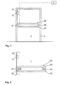
- FIG. 1 schematically a system for a door 1 is shown, which has a self-locking door lock 10 and an unlocking device 20.
- the self-locking door lock 10 can be brought between a normal operation and an emergency operation. Is the door 1 in the closed state, as in FIG. 1 shown, the door lock is in normal operation.
- the normal operation of the self-locking door lock 10 means that the door lock 10 is in a locked state, so that the door 1 can not be opened.
- the door lock 10 is designed monostable, so that is formed as a stable state of the locking state. In the present case, this means that when the door 1 is brought from a not explicitly shown open state to the closed state, the door lock 10 is automatically brought into its locked state.
- the door lock 10 has at least one movable locking element 12 which can be moved out of the door lock 10 as a function of normal operation or emergency operation (locking state). or can be pulled into the door latch 10 (unlock state). In an emergency operation, the door lock 10 is changed to the unlocked state.
- the emergency operation can be triggered, for example, by fire, fire, power failure, etc., so that the possibility is created within the system according to the invention that the door 1 is released for opening to the user.
- the unlocking device 20 has an actuating element 28, which runs horizontally along the door leaf.
- the actuator 28 may, for. B. be designed as a pressure bar or panic bar, which are in an emergency situation, as described above, to be operated by the user. In an emergency or panic situation, the escaping user can easily push or pivot the actuator 28 to allow the door 1 to be opened.
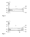
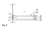
- the peculiarity of this system is that for the emergency situation, the user first has an emergency button 30, which in the FIGS. 2 to 10 is shown on the housing 22 of the unlocking device 20 has to operate.
- the emergency button 30 is in this case integrated within the housing 22 of the unlocking device 20 and is simultaneously in communication with the door lock 10.
- the unlocking device 20 may be designed such that an externally accessible, personal button 40 is provided on the housing 22, the only allows a certain group of people to operate the self-locking door lock 10. This means that the door lock 10 can be brought between the locked state and the unlocked state via the personal button 40.
- the personal button 40 may be a key switch, a non-contact button or a manually operated button. It is also conceivable that upon activation of the personal button 40, a simultaneous authentication query between the user and the button 40 takes place.
- the button 40 may be wirelessly connected to the door latch 10. Also, a wired connection between the two components 10, 40 is conceivable.
- FIG. 2 is the actuator 28 between the emergency button 30 and the personal button 40.
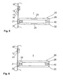
- This embodiment has proven to be particularly user-friendly. In some applications, it may also be advantageous to arrange the emergency button 30 and the personal button 40 directly next to each other on the housing 22 of the unlocking device 20, which in FIG. 3 is shown.
- the system according to the invention in particular the unlocking device 20 and / or the door lock 10 with at least one energy storage 11, 27 is formed (see FIG. 4 ).
- the door lock 10 and / or the unlocking device 20 are connected to an external power grid.
- the energy storage 11 may, for. B. be provided to drive the explicitly not shown in the embodiments electric motor, which provides for the change between the locking state and the unlocking state of the self-locking door lock 10.
- the energy storage 27 within the housing 22 may be connected to the emergency button 30 and / or the personal button 40, for example, and supply them electrically.
- the supply of both buttons 30, 40 can be done both in normal operation and in emergency operation.
- the unlocking device 20 may have a light element 23 on the housing 22, which emits a corresponding alarm signal optically.
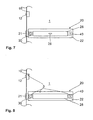
- the housing 22 of the unlocking device 20 may have a smoke detector / smoke detector 25 which can detect an emergency, in particular detect a fire in the vicinity of the system according to the invention.
- the smoke detector / smoke detector 25 is operatively connected or in communication with the door lock 10 or with a security unit 4 arranged inside the building. Based on the signal emitted by the smoke detector / smoke detector 25, the self-locking door lock 10 can be switched to emergency mode.
- FIG. 7 schematically shows that a sensor device 26 may be disposed within the housing 22 of the unlocking device 20, which detects to what extent the actuator 28 has been actually operated by a user.
- the sensor device 26 may be in data communication with the unlocking device 20 as well as with the security unit 4.
- the communication between the door lock 10, the unlocking device 20 and / or with the security unit 4 can be wireless, for example via radio.
- the door lock 10, the unlocking device 20 corresponding communication interfaces 3.
- the communication interfaces 3 can be transmitting and / or receiving units that can communicate with each other. It is also conceivable that a wired connection between the door lock 10, the unlocking device 20 and / or the security unit 4 is present.
- the door lock 10 may be integrated within the housing 22 of the unlocking device 20. In this way, a particularly compact unit can be created, whereby the assembly cost of the system according to the invention can be reduced to the door 1.
- FIG. 2 to FIG. 9 are shown, of course, can be combined with each other.
- the emergency button 30 may be formed as a touch button, proximity button, manually operated button or switch.
- the emergency button 30 may be formed with its own light element, which is easy to recognize by the user.
- the color of the light element may vary depending on the normal operation and emergency operation.
- the emergency button 30 can z. B. be covered by a cover from the outside world. To actually activate the emergency button 30, it is necessary for the user to remove, pivot, push away the cover, etc., to access the emergency button 30 located beneath the cover.
- the cover is advantageously light transparent so that the user reliably recognizes the emergency button 30 from the outside.
- the person-bound push-button 40 has at the same time the lock cylinder of the door 1, which is used for the locking and / or unlocking of the door 1.
- the door lock 10 has a loudspeaker 14 and / or a light element 15 in order to allow the user to recognize the emergency operation.
- the door lock 10 is equipped with a smoke detector / smoke detector 13.
Landscapes
- Business, Economics & Management (AREA)
- Emergency Management (AREA)
- Engineering & Computer Science (AREA)
- Structural Engineering (AREA)
- Lock And Its Accessories (AREA)
Applications Claiming Priority (1)
| Application Number | Priority Date | Filing Date | Title |
|---|---|---|---|
| DE102011053348A DE102011053348A1 (de) | 2011-09-07 | 2011-09-07 | System für eine Tür |
Publications (4)
| Publication Number | Publication Date |
|---|---|
| EP2568100A2 true EP2568100A2 (fr) | 2013-03-13 |
| EP2568100A3 EP2568100A3 (fr) | 2017-05-24 |
| EP2568100B1 EP2568100B1 (fr) | 2020-05-13 |
| EP2568100B2 EP2568100B2 (fr) | 2024-02-14 |
Family
ID=46963355
Family Applications (1)
| Application Number | Title | Priority Date | Filing Date |
|---|---|---|---|
| EP12005795.5A Active EP2568100B2 (fr) | 2011-09-07 | 2012-08-09 | Système pour une porte |
Country Status (3)
| Country | Link |
|---|---|
| EP (1) | EP2568100B2 (fr) |
| DE (1) | DE102011053348A1 (fr) |
| ES (1) | ES2796225T3 (fr) |
Cited By (5)
| Publication number | Priority date | Publication date | Assignee | Title |
|---|---|---|---|---|
| EP2921616A1 (fr) * | 2014-03-18 | 2015-09-23 | Gretsch-Unitas GmbH Baubeschläge | Dispositif pour une sortie de secours |
| CN105336078A (zh) * | 2015-12-07 | 2016-02-17 | 济南大学 | 一种家用智能防盗报警系统 |
| WO2016147207A1 (fr) * | 2015-03-18 | 2016-09-22 | Cisa S.P.A. | Ensemble indicateur pour l'entretien ordinaire et extraordinaire des poignées et des barres de panique |
| EP3267457A1 (fr) * | 2016-07-04 | 2018-01-10 | dormakaba Deutschland GmbH | Système de sécurité |
| EP3267453A1 (fr) * | 2016-07-04 | 2018-01-10 | dormakaba Deutschland GmbH | Système de sécurité |
Families Citing this family (4)
| Publication number | Priority date | Publication date | Assignee | Title |
|---|---|---|---|---|
| MX2015012310A (es) | 2013-03-13 | 2016-07-21 | Spectrum Brands Inc | Sistema de bloqueo interconectado. |
| JP7022652B2 (ja) * | 2018-05-30 | 2022-02-18 | 株式会社シブタニ | スライドラッチ錠 |
| DE102019100830A1 (de) * | 2019-01-14 | 2020-07-16 | Eco Schulte Gmbh & Co. Kg | Panikschloss mit Informationsbeleuchtung |
| US11414892B2 (en) * | 2019-12-03 | 2022-08-16 | Schlage Lock Company Llc | Exit device trim locking |
Citations (1)
| Publication number | Priority date | Publication date | Assignee | Title |
|---|---|---|---|---|
| DE102009047852B4 (de) | 2009-09-30 | 2011-07-07 | ASSA ABLOY Sicherheitstechnik GmbH, 72458 | Türüberwachungsvorrichtung |
Family Cites Families (9)
| Publication number | Priority date | Publication date | Assignee | Title |
|---|---|---|---|---|
| US5429399A (en) † | 1992-10-22 | 1995-07-04 | Geringer; Arthur | Electronic delayed egress locking system |
| DE19531323A1 (de) * | 1994-10-15 | 1996-04-18 | Geze Gmbh & Co | Ein Diagnose- und/oder Überwachungsverfahren und eine Sicherheitseinrichtung zur Durchführung des Verfahrens für mindestens eine Tür, vorzugsweise in Flucht- und Rettungswegen |
| DE19909953A1 (de) † | 1999-03-06 | 2000-09-07 | Geze Glas Design Gmbh | Sicherungs- und Überwachungseinrichtung |
| DE10013295A1 (de) * | 2000-03-17 | 2001-09-20 | Geze Gmbh | Tür in Flucht- und Rettungswegen |
| DE10043979A1 (de) † | 2000-09-05 | 2002-03-14 | Geze Gmbh | Sicherungs- und/oder Überwachungsvorrichtung |
| DE10064956A1 (de) * | 2000-12-23 | 2002-06-27 | Geze Gmbh | Sicherungsvorrichtung für eine Tür in Flucht- und Rettungswegen |
| US7469942B2 (en) † | 2002-09-30 | 2008-12-30 | Yale Security Inc. | Delayed egress exit device |
| DE10257721B4 (de) * | 2002-12-11 | 2005-08-04 | Landert-Motoren-AG, Bülach | Steuerungssystem für eine Türanlage |
| US7862091B2 (en) * | 2004-10-12 | 2011-01-04 | Command Access Technology, LLC | Electromechanical door solenoid current surge booster circuit |
-
2011
- 2011-09-07 DE DE102011053348A patent/DE102011053348A1/de active Pending
-
2012
- 2012-08-09 ES ES12005795T patent/ES2796225T3/es active Active
- 2012-08-09 EP EP12005795.5A patent/EP2568100B2/fr active Active
Patent Citations (1)
| Publication number | Priority date | Publication date | Assignee | Title |
|---|---|---|---|---|
| DE102009047852B4 (de) | 2009-09-30 | 2011-07-07 | ASSA ABLOY Sicherheitstechnik GmbH, 72458 | Türüberwachungsvorrichtung |
Cited By (7)
| Publication number | Priority date | Publication date | Assignee | Title |
|---|---|---|---|---|
| EP2921616A1 (fr) * | 2014-03-18 | 2015-09-23 | Gretsch-Unitas GmbH Baubeschläge | Dispositif pour une sortie de secours |
| EP2921616B1 (fr) | 2014-03-18 | 2017-07-19 | Gretsch-Unitas GmbH Baubeschläge | Dispositif pour une sortie de secours |
| WO2016147207A1 (fr) * | 2015-03-18 | 2016-09-22 | Cisa S.P.A. | Ensemble indicateur pour l'entretien ordinaire et extraordinaire des poignées et des barres de panique |
| CN105336078A (zh) * | 2015-12-07 | 2016-02-17 | 济南大学 | 一种家用智能防盗报警系统 |
| EP3267457A1 (fr) * | 2016-07-04 | 2018-01-10 | dormakaba Deutschland GmbH | Système de sécurité |
| EP3267453A1 (fr) * | 2016-07-04 | 2018-01-10 | dormakaba Deutschland GmbH | Système de sécurité |
| EP3267453B1 (fr) | 2016-07-04 | 2022-06-08 | dormakaba Deutschland GmbH | Système de sécurité |
Also Published As
| Publication number | Publication date |
|---|---|
| EP2568100B2 (fr) | 2024-02-14 |
| EP2568100A3 (fr) | 2017-05-24 |
| ES2796225T3 (es) | 2020-11-26 |
| DE102011053348A1 (de) | 2013-03-07 |
| EP2568100B1 (fr) | 2020-05-13 |
Similar Documents
| Publication | Publication Date | Title |
|---|---|---|
| EP2568100B2 (fr) | Système pour une porte | |
| EP0589158B1 (fr) | Serrure commandable à distance, en particulier pour des portières de véhicule automobile | |
| EP1785963B1 (fr) | Système pour effrayer des individus éssayant d'activer une porte d'évacuation d'une voie de sortie. | |
| DE102009016185A1 (de) | Passives Entriegelungssystem und -verfahren | |
| DE102013007154A1 (de) | Kraftfahrzeug mit einem Zentralverriegelungssystem | |
| DE102008018906B4 (de) | Schließzylinderanordnung | |
| DE102014112122B4 (de) | Verfahren zum Sperren und Freigeben eines Türblatts und Türanordnung | |
| DE112013000977T5 (de) | Automatische Türsteuereinrichtung und Türbetätigungsgerät | |
| EP2058460B9 (fr) | Dispositif de verrouillage anti-effraction pour batiment | |
| EP0949396B1 (fr) | Dispositif de verrouillage d'une fenêtre basculante pour un installation de protection d'objets | |
| DE10104010A1 (de) | Türschließsystem | |
| EP2350981B1 (fr) | Système de contrôle et de commande d' accès | |
| EP0949597B1 (fr) | Verrou mécanique pour fenêtre ou porte d'une installation pour la securité d'objets fonctionnant sans fil | |
| DE10208452A1 (de) | Türschlossüberwachungseinheit | |
| EP3686385A1 (fr) | Unité électronique ainsi que système d'accès | |
| EP3267455B1 (fr) | Système de sécurité | |
| EP2161397A2 (fr) | Dispositif de fixation ou de surveillance de tiges d'actionnement sur des portes de sortie de secours, de portes anti-panique ou analogues | |
| EP1160398B1 (fr) | Serrure à commande électrique | |
| DE102011008239A1 (de) | Blockiereinrichtung bzw. Vorrichtung zur Scharf-/Unscharfschaltung einer Alarm- bzw. Einbruchmeldeanlage mit Blockierung einer Verschluss-, Sperr-, Entsperr-, Betätigungs- oder Bedieneinrichtung unter Einhaltung der sogenannten Zwangsläufigkeit | |
| DE19815766A1 (de) | Mechanische Fenster- oder Türverriegelung einer drahtlos arbeitenden Objektsicherungsanlage | |
| DE102016123574A1 (de) | Sicherungsvorrichtung | |
| EP2636825A2 (fr) | Dispositif et système de verrouillage | |
| EP1580363B1 (fr) | Dispositif pour protection ou surveillance des issues de secours ou similaire | |
| DE19815767A1 (de) | Objektsicherungsanlage | |
| EP3267454B1 (fr) | Système de sécurité |
Legal Events
| Date | Code | Title | Description |
|---|---|---|---|
| PUAI | Public reference made under article 153(3) epc to a published international application that has entered the european phase |
Free format text: ORIGINAL CODE: 0009012 |
|
| AK | Designated contracting states |
Kind code of ref document: A2 Designated state(s): AL AT BE BG CH CY CZ DE DK EE ES FI FR GB GR HR HU IE IS IT LI LT LU LV MC MK MT NL NO PL PT RO RS SE SI SK SM TR |
|
| AX | Request for extension of the european patent |
Extension state: BA ME |
|
| RAP1 | Party data changed (applicant data changed or rights of an application transferred) |
Owner name: DORMA DEUTSCHLAND GMBH |
|
| PUAL | Search report despatched |
Free format text: ORIGINAL CODE: 0009013 |
|
| RAP1 | Party data changed (applicant data changed or rights of an application transferred) |
Owner name: DORMAKABA DEUTSCHLAND GMBH |
|
| AK | Designated contracting states |
Kind code of ref document: A3 Designated state(s): AL AT BE BG CH CY CZ DE DK EE ES FI FR GB GR HR HU IE IS IT LI LT LU LV MC MK MT NL NO PL PT RO RS SE SI SK SM TR |
|
| AX | Request for extension of the european patent |
Extension state: BA ME |
|
| RIC1 | Information provided on ipc code assigned before grant |
Ipc: E05B 17/22 20060101ALI20170418BHEP Ipc: E05B 65/10 20060101ALI20170418BHEP Ipc: E05B 63/14 20060101ALI20170418BHEP Ipc: E05B 45/06 20060101AFI20170418BHEP |
|
| STAA | Information on the status of an ep patent application or granted ep patent |
Free format text: STATUS: REQUEST FOR EXAMINATION WAS MADE |
|
| 17P | Request for examination filed |
Effective date: 20171120 |
|
| RBV | Designated contracting states (corrected) |
Designated state(s): AL AT BE BG CH CY CZ DE DK EE ES FI FR GB GR HR HU IE IS IT LI LT LU LV MC MK MT NL NO PL PT RO RS SE SI SK SM TR |
|
| STAA | Information on the status of an ep patent application or granted ep patent |
Free format text: STATUS: EXAMINATION IS IN PROGRESS |
|
| 17Q | First examination report despatched |
Effective date: 20190423 |
|
| GRAP | Despatch of communication of intention to grant a patent |
Free format text: ORIGINAL CODE: EPIDOSNIGR1 |
|
| STAA | Information on the status of an ep patent application or granted ep patent |
Free format text: STATUS: GRANT OF PATENT IS INTENDED |
|
| INTG | Intention to grant announced |
Effective date: 20191206 |
|
| GRAS | Grant fee paid |
Free format text: ORIGINAL CODE: EPIDOSNIGR3 |
|
| GRAA | (expected) grant |
Free format text: ORIGINAL CODE: 0009210 |
|
| STAA | Information on the status of an ep patent application or granted ep patent |
Free format text: STATUS: THE PATENT HAS BEEN GRANTED |
|
| AK | Designated contracting states |
Kind code of ref document: B1 Designated state(s): AL AT BE BG CH CY CZ DE DK EE ES FI FR GB GR HR HU IE IS IT LI LT LU LV MC MK MT NL NO PL PT RO RS SE SI SK SM TR |
|
| REG | Reference to a national code |
Ref country code: GB Ref legal event code: FG4D Free format text: NOT ENGLISH |
|
| REG | Reference to a national code |
Ref country code: CH Ref legal event code: EP |
|
| REG | Reference to a national code |
Ref country code: DE Ref legal event code: R096 Ref document number: 502012016070 Country of ref document: DE |
|
| REG | Reference to a national code |
Ref country code: CH Ref legal event code: NV Representative=s name: FREI PATENTANWALTSBUERO AG, CH |
|
| REG | Reference to a national code |
Ref country code: AT Ref legal event code: REF Ref document number: 1270480 Country of ref document: AT Kind code of ref document: T Effective date: 20200615 |
|
| REG | Reference to a national code |
Ref country code: SE Ref legal event code: TRGR |
|
| REG | Reference to a national code |
Ref country code: LT Ref legal event code: MG4D |
|
| REG | Reference to a national code |
Ref country code: NL Ref legal event code: MP Effective date: 20200513 |
|
| PG25 | Lapsed in a contracting state [announced via postgrant information from national office to epo] |
Ref country code: IS Free format text: LAPSE BECAUSE OF FAILURE TO SUBMIT A TRANSLATION OF THE DESCRIPTION OR TO PAY THE FEE WITHIN THE PRESCRIBED TIME-LIMIT Effective date: 20200913 Ref country code: PT Free format text: LAPSE BECAUSE OF FAILURE TO SUBMIT A TRANSLATION OF THE DESCRIPTION OR TO PAY THE FEE WITHIN THE PRESCRIBED TIME-LIMIT Effective date: 20200914 Ref country code: FI Free format text: LAPSE BECAUSE OF FAILURE TO SUBMIT A TRANSLATION OF THE DESCRIPTION OR TO PAY THE FEE WITHIN THE PRESCRIBED TIME-LIMIT Effective date: 20200513 Ref country code: LT Free format text: LAPSE BECAUSE OF FAILURE TO SUBMIT A TRANSLATION OF THE DESCRIPTION OR TO PAY THE FEE WITHIN THE PRESCRIBED TIME-LIMIT Effective date: 20200513 Ref country code: GR Free format text: LAPSE BECAUSE OF FAILURE TO SUBMIT A TRANSLATION OF THE DESCRIPTION OR TO PAY THE FEE WITHIN THE PRESCRIBED TIME-LIMIT Effective date: 20200814 Ref country code: NO Free format text: LAPSE BECAUSE OF FAILURE TO SUBMIT A TRANSLATION OF THE DESCRIPTION OR TO PAY THE FEE WITHIN THE PRESCRIBED TIME-LIMIT Effective date: 20200813 |
|
| REG | Reference to a national code |
Ref country code: ES Ref legal event code: FG2A Ref document number: 2796225 Country of ref document: ES Kind code of ref document: T3 Effective date: 20201126 |
|
| PG25 | Lapsed in a contracting state [announced via postgrant information from national office to epo] |
Ref country code: BG Free format text: LAPSE BECAUSE OF FAILURE TO SUBMIT A TRANSLATION OF THE DESCRIPTION OR TO PAY THE FEE WITHIN THE PRESCRIBED TIME-LIMIT Effective date: 20200813 Ref country code: LV Free format text: LAPSE BECAUSE OF FAILURE TO SUBMIT A TRANSLATION OF THE DESCRIPTION OR TO PAY THE FEE WITHIN THE PRESCRIBED TIME-LIMIT Effective date: 20200513 Ref country code: HR Free format text: LAPSE BECAUSE OF FAILURE TO SUBMIT A TRANSLATION OF THE DESCRIPTION OR TO PAY THE FEE WITHIN THE PRESCRIBED TIME-LIMIT Effective date: 20200513 Ref country code: RS Free format text: LAPSE BECAUSE OF FAILURE TO SUBMIT A TRANSLATION OF THE DESCRIPTION OR TO PAY THE FEE WITHIN THE PRESCRIBED TIME-LIMIT Effective date: 20200513 |
|
| PG25 | Lapsed in a contracting state [announced via postgrant information from national office to epo] |
Ref country code: NL Free format text: LAPSE BECAUSE OF FAILURE TO SUBMIT A TRANSLATION OF THE DESCRIPTION OR TO PAY THE FEE WITHIN THE PRESCRIBED TIME-LIMIT Effective date: 20200513 Ref country code: AL Free format text: LAPSE BECAUSE OF FAILURE TO SUBMIT A TRANSLATION OF THE DESCRIPTION OR TO PAY THE FEE WITHIN THE PRESCRIBED TIME-LIMIT Effective date: 20200513 |
|
| PG25 | Lapsed in a contracting state [announced via postgrant information from national office to epo] |
Ref country code: DK Free format text: LAPSE BECAUSE OF FAILURE TO SUBMIT A TRANSLATION OF THE DESCRIPTION OR TO PAY THE FEE WITHIN THE PRESCRIBED TIME-LIMIT Effective date: 20200513 Ref country code: RO Free format text: LAPSE BECAUSE OF FAILURE TO SUBMIT A TRANSLATION OF THE DESCRIPTION OR TO PAY THE FEE WITHIN THE PRESCRIBED TIME-LIMIT Effective date: 20200513 Ref country code: IT Free format text: LAPSE BECAUSE OF FAILURE TO SUBMIT A TRANSLATION OF THE DESCRIPTION OR TO PAY THE FEE WITHIN THE PRESCRIBED TIME-LIMIT Effective date: 20200513 Ref country code: CZ Free format text: LAPSE BECAUSE OF FAILURE TO SUBMIT A TRANSLATION OF THE DESCRIPTION OR TO PAY THE FEE WITHIN THE PRESCRIBED TIME-LIMIT Effective date: 20200513 Ref country code: EE Free format text: LAPSE BECAUSE OF FAILURE TO SUBMIT A TRANSLATION OF THE DESCRIPTION OR TO PAY THE FEE WITHIN THE PRESCRIBED TIME-LIMIT Effective date: 20200513 Ref country code: SM Free format text: LAPSE BECAUSE OF FAILURE TO SUBMIT A TRANSLATION OF THE DESCRIPTION OR TO PAY THE FEE WITHIN THE PRESCRIBED TIME-LIMIT Effective date: 20200513 |
|
| REG | Reference to a national code |
Ref country code: DE Ref legal event code: R026 Ref document number: 502012016070 Country of ref document: DE |
|
| PLBI | Opposition filed |
Free format text: ORIGINAL CODE: 0009260 |
|
| PG25 | Lapsed in a contracting state [announced via postgrant information from national office to epo] |
Ref country code: PL Free format text: LAPSE BECAUSE OF FAILURE TO SUBMIT A TRANSLATION OF THE DESCRIPTION OR TO PAY THE FEE WITHIN THE PRESCRIBED TIME-LIMIT Effective date: 20200513 Ref country code: SK Free format text: LAPSE BECAUSE OF FAILURE TO SUBMIT A TRANSLATION OF THE DESCRIPTION OR TO PAY THE FEE WITHIN THE PRESCRIBED TIME-LIMIT Effective date: 20200513 |
|
| PLAX | Notice of opposition and request to file observation + time limit sent |
Free format text: ORIGINAL CODE: EPIDOSNOBS2 |
|
| 26 | Opposition filed |
Opponent name: ASSA ABLOY SICHERHEITSTECHNIK GMBH Effective date: 20210212 |
|
| PG25 | Lapsed in a contracting state [announced via postgrant information from national office to epo] |
Ref country code: MC Free format text: LAPSE BECAUSE OF FAILURE TO SUBMIT A TRANSLATION OF THE DESCRIPTION OR TO PAY THE FEE WITHIN THE PRESCRIBED TIME-LIMIT Effective date: 20200513 |
|
| PG25 | Lapsed in a contracting state [announced via postgrant information from national office to epo] |
Ref country code: LU Free format text: LAPSE BECAUSE OF NON-PAYMENT OF DUE FEES Effective date: 20200809 |
|
| PG25 | Lapsed in a contracting state [announced via postgrant information from national office to epo] |
Ref country code: SI Free format text: LAPSE BECAUSE OF FAILURE TO SUBMIT A TRANSLATION OF THE DESCRIPTION OR TO PAY THE FEE WITHIN THE PRESCRIBED TIME-LIMIT Effective date: 20200513 |
|
| PLBB | Reply of patent proprietor to notice(s) of opposition received |
Free format text: ORIGINAL CODE: EPIDOSNOBS3 |
|
| PG25 | Lapsed in a contracting state [announced via postgrant information from national office to epo] |
Ref country code: FR Free format text: LAPSE BECAUSE OF NON-PAYMENT OF DUE FEES Effective date: 20200831 |
|
| PG25 | Lapsed in a contracting state [announced via postgrant information from national office to epo] |
Ref country code: IE Free format text: LAPSE BECAUSE OF NON-PAYMENT OF DUE FEES Effective date: 20200809 |
|
| PG25 | Lapsed in a contracting state [announced via postgrant information from national office to epo] |
Ref country code: TR Free format text: LAPSE BECAUSE OF FAILURE TO SUBMIT A TRANSLATION OF THE DESCRIPTION OR TO PAY THE FEE WITHIN THE PRESCRIBED TIME-LIMIT Effective date: 20200513 Ref country code: MT Free format text: LAPSE BECAUSE OF FAILURE TO SUBMIT A TRANSLATION OF THE DESCRIPTION OR TO PAY THE FEE WITHIN THE PRESCRIBED TIME-LIMIT Effective date: 20200513 Ref country code: CY Free format text: LAPSE BECAUSE OF FAILURE TO SUBMIT A TRANSLATION OF THE DESCRIPTION OR TO PAY THE FEE WITHIN THE PRESCRIBED TIME-LIMIT Effective date: 20200513 |
|
| PG25 | Lapsed in a contracting state [announced via postgrant information from national office to epo] |
Ref country code: MK Free format text: LAPSE BECAUSE OF FAILURE TO SUBMIT A TRANSLATION OF THE DESCRIPTION OR TO PAY THE FEE WITHIN THE PRESCRIBED TIME-LIMIT Effective date: 20200513 |
|
| REG | Reference to a national code |
Ref country code: CH Ref legal event code: PK Free format text: BERICHTIGUNGEN |
|
| RIC2 | Information provided on ipc code assigned after grant |
Ipc: E05B 63/20 20060101ALI20221121BHEP Ipc: E05B 63/14 20060101ALI20221121BHEP Ipc: E05B 17/22 20060101ALI20221121BHEP Ipc: E05B 65/10 20060101ALI20221121BHEP Ipc: E05B 45/06 20060101AFI20221121BHEP |
|
| APAH | Appeal reference modified |
Free format text: ORIGINAL CODE: EPIDOSCREFNO |
|
| APBM | Appeal reference recorded |
Free format text: ORIGINAL CODE: EPIDOSNREFNO |
|
| APBP | Date of receipt of notice of appeal recorded |
Free format text: ORIGINAL CODE: EPIDOSNNOA2O |
|
| APBQ | Date of receipt of statement of grounds of appeal recorded |
Free format text: ORIGINAL CODE: EPIDOSNNOA3O |
|
| APBU | Appeal procedure closed |
Free format text: ORIGINAL CODE: EPIDOSNNOA9O |
|
| PGFP | Annual fee paid to national office [announced via postgrant information from national office to epo] |
Ref country code: GB Payment date: 20230822 Year of fee payment: 12 Ref country code: CH Payment date: 20230902 Year of fee payment: 12 Ref country code: AT Payment date: 20230822 Year of fee payment: 12 |
|
| PGFP | Annual fee paid to national office [announced via postgrant information from national office to epo] |
Ref country code: SE Payment date: 20230821 Year of fee payment: 12 Ref country code: DE Payment date: 20230821 Year of fee payment: 12 Ref country code: BE Payment date: 20230821 Year of fee payment: 12 |
|
| PUAH | Patent maintained in amended form |
Free format text: ORIGINAL CODE: 0009272 |
|
| STAA | Information on the status of an ep patent application or granted ep patent |
Free format text: STATUS: PATENT MAINTAINED AS AMENDED |
|
| PGFP | Annual fee paid to national office [announced via postgrant information from national office to epo] |
Ref country code: ES Payment date: 20231027 Year of fee payment: 12 |
|
| 27A | Patent maintained in amended form |
Effective date: 20240214 |
|
| AK | Designated contracting states |
Kind code of ref document: B2 Designated state(s): AL AT BE BG CH CY CZ DE DK EE ES FI FR GB GR HR HU IE IS IT LI LT LU LV MC MK MT NL NO PL PT RO RS SE SI SK SM TR |
|
| REG | Reference to a national code |
Ref country code: DE Ref legal event code: R102 Ref document number: 502012016070 Country of ref document: DE |