EP2564181B1 - Portable viscometer - Google Patents
Portable viscometer Download PDFInfo
- Publication number
- EP2564181B1 EP2564181B1 EP11777928.0A EP11777928A EP2564181B1 EP 2564181 B1 EP2564181 B1 EP 2564181B1 EP 11777928 A EP11777928 A EP 11777928A EP 2564181 B1 EP2564181 B1 EP 2564181B1
- Authority
- EP
- European Patent Office
- Prior art keywords
- pipette
- liquid
- viscosity
- viscometer
- sample
- Prior art date
- Legal status (The legal status is an assumption and is not a legal conclusion. Google has not performed a legal analysis and makes no representation as to the accuracy of the status listed.)
- Active
Links
Images

Classifications
-
- G—PHYSICS
- G01—MEASURING; TESTING
- G01N—INVESTIGATING OR ANALYSING MATERIALS BY DETERMINING THEIR CHEMICAL OR PHYSICAL PROPERTIES
- G01N11/00—Investigating flow properties of materials, e.g. viscosity, plasticity; Analysing materials by determining flow properties
- G01N11/02—Investigating flow properties of materials, e.g. viscosity, plasticity; Analysing materials by determining flow properties by measuring flow of the material
- G01N11/04—Investigating flow properties of materials, e.g. viscosity, plasticity; Analysing materials by determining flow properties by measuring flow of the material through a restricted passage, e.g. tube, aperture
- G01N11/08—Investigating flow properties of materials, e.g. viscosity, plasticity; Analysing materials by determining flow properties by measuring flow of the material through a restricted passage, e.g. tube, aperture by measuring pressure required to produce a known flow
Definitions
- This invention is in the field of viscometers that measure viscosity of liquids utilizing a flow-through type viscosity sensor.
- Viscosity is a measure of resistance of liquid to flow and its value depends on the rate of deformation for Non-Newtonian liquids as described in Dynamics of Polymeric Liquids, Vol. 1, 1987, authored by R.B. Bird, R.C. Armstrong, and O. Hassager .
- the rate of deformation is given by a shear rate in a unit of (time) -1 .
- the viscosity measured at a known shear rate is "true" viscosity.
- the dependence of the true viscosity on shear rate is a viscosity curve which characterizes material and is an important factor to consider for efficient processing. However, in many cases, viscosity is measured under ill-defined test condition so that shear rate cannot be known or calculated.
- the measured viscosity value is only "apparent". Since the true viscosity is measured at a known shear rate, the true viscosity is universal whereas the apparent viscosity is not. Instead, the apparent viscosity depends on the measuring system. For example, as a common practice, a torque of a spindle immersed in a sea of test liquid is measured while the spindle is being rotated at a constant speed. In this case the torque value only yields an apparent viscosity since the test condition is ill-defined and a shear rate is not known. At best, the apparent viscosity can be measured as a function of the rotational speed of the spindle.
- the rotational speed of the spindle can be in fact correlated with the shear rate only if a "constitutive equation" for the test liquid is known.
- a "constitutive equation” is not known for almost all Non-Newtonian liquids. Therefore, true viscosity cannot be measured with ill-defined test conditions for most non-Newtonian liquids.
- the rheometers impose a precise and known shear rate on test samples, thereby measuring true viscosities.
- the rheometers are versatile and usually equipped to also measure other properties. Therefore they are usually expensive. Further, large amounts of samples are usually required for viscosity measurement with a rheometer. Also, rheometers are not well suited for on-line applications. Circular capillary viscometers can measure apparent and true viscosities depending on whether a proper compensation is taken into account.
- the capillary viscometer needs a pressure drop measurement along the capillary for viscosity. Since the capillary is circular in cross-section, only pressure at the entrance and exit can be measured.
- capillary viscometer measures only apparent viscosity unless the entrance effect is corrected for by using two different capillaries with different length to diameter ratios.
- use of two capillaries makes the capillary viscometers bulky and/or time consuming.
- Capillary viscometers are described in Patent Nos. 6,575,019 (Larson ); 4,920,787 (Dual et al. ); 4,916,678 (Johnson et al. ); and 4,793,174 (Yau ).
- Microfluidic viscometers are disclosed in Patent No. 6,681,616 (Michael Spaid et al. ) and Publication No. 2003/0182991 (Michael Spaid et al.
- a portable viscometer is defined in claim 1, and additional features are defined in dependent claims 2-15.
- the sensor design is described in Patent Nos. 6,892,583 and 7,290,441 .
- the portable system of the current invention measures the true viscosity of a liquid and requires only small volume samples of the liquid for measurement.
- the invention also provides a fast and easy way to obtain samples of liquid to be tested and to insert the samples of liquid into the viscometer for testing.
- the portable precision liquid dispensing system of the invention includes a positive displacement pump which operates in conjunction with a positive displacement sample container, which will be referred to as a positive displacement pipette, in which the sample of the liquid for which the viscosity is to be measured is supplied.
- the pipette may be removable from and replaceable in the viscometer so that a sample of liquid to be tested can be drawn into the pipette when removed and separate from the viscometer and the pipette with the sample of liquid therein then inserted into the viscometer for measuring the viscosity of the sample of liquid in the pipette.
- the pipette includes a plunger that slides within the pipette to draw a sample into the pipette (this can be done by hand) and to force the sample from the pipette when in the viscometer.
- a precision motor drives a lead screw which moves a push back in contact with the pipette plunger when positioned in the viscometer. As the push back moves the plunger in the pipette, liquid is dispensed from the pipette into a flow passage of the miniature viscosity measurement sensor.
- Control electronics control operation of the precision motor to dispense the liquid to be tested from the pipette at a known flow rate into the flow passage of the miniature viscosity measurement sensor.
- the miniature flow-through viscosity measurement sensor includes a micron scale flow channel combined with a pressure sensor array which measures the pressure drop of a fully developed flow of the liquid in the flow channel.
- the pressure drop is proportional to the shear stress of the liquid flowing through the channel.
- the shear rate is proportional to flow rate.
- Viscosity of the sample liquid is calculated by dividing the shear stress by the shear rate.
- the resulting measurement of viscosity can be shown in a display.
- Microcontroller or microprocessor based electronics can form the controller electronics of the viscometer to control the motor of the pump and process the data from the pressure sensors.
- the processed data can be displayed and may also be stored and/or sent to remote devices.
- the viscometer, the viscosity sensor, and/or the sample in the pipette may be conditioned to a set temperature with a peltier based temperature control device or other generally accepted temperature control means.
- the viscometer may store a history of measured viscosity values for various uses and/or may store a database of the known viscosity values of various liquids, such as liquids frequently expected to be measured. This can allow a quick comparison of the known viscosity of a known liquid with the measured viscosity of a sample thought to be the known liquid. Discrepancies between the known value and the measured value can indicate that the test liquid is not the liquid it is thought to be or can indicate problems with the viscometer so that the viscometer can be checked.
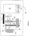
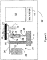
- the viscometer 22 includes a precision pump, indicated generally by reference number 20, a liquid container 14 for supplying a sample of the liquid for which a viscosity measurement is desired, a flow-through viscosity sensor 15, a controller 18, and a display 19.
- the pump 20 works in conjunction with a sample container shown and referred to as a pipette 14 having a pipette barrel or body 13 and a plunger 12 slidably positioned in the pipette barrel 13 with plunger end portion 24 extending from an end of the barrel 13.
- the pipette 14 may be removably positioned and held in the viscometer by a mounting mechanism 28 so the pipette can be removed, filled with a sample of liquid to be tested, and replaced into the mounting mechanism of the viscometer, or can be removed and replaced with another similar pipette containing a sample of liquid to be tested.
- the pipette may be made disposable so a new, clean pipette is used for each sample of liquid.
- the pump includes a precision motor 23, a lead screw 10 rotatable by the motor 23 through a drive mechanism 26, such as a gear drive or belt drive, and a push back 11 mounted on lead screw 10 which contacts the end 25 of pipette plunger end portion 24 when pipette 14 is positioned in the viscometer.
- the push back 11 moves laterally along lead screw 10 in response to the rotation of the lead screw 10 by motor 23.
- a pipette plunger 41 has a plunger head 42 sealingly and slidably received in pipette barrel 40 with an end portion 45 extending from an end of the pipette barrel 40.
- Both the pipette barrel and pipette plunger can be fabricated from plastic by injection molding. The plunger can slide back and forth inside of the barrel 40.
- the end of plunger head 42 is shaped to closely fit into liquid flow barrel end 43, as shown in Fig. 4 , to minimize any air gap 44 between the two.
- the liquid flow end 43 of the pipette can be inserted into a liquid for which the viscosity is to be determined.
- a user can grasp the end portion 45 of the plunger 41 extending from the pipette barrel 40 and pull the plunger back from the end 43 of the pipette barrel to draw sample into the pipette barrel through an opening in barrel end 43.
- Fig. 3 shows the plunger 41 pulled back from the barrel end to create space 46 in the pipette barrel which will contain the liquid sample drawn into the pipette.
- sample will continue to be drawn into the increasing space 46.
- the user stops pulling back the plunger 41 when the desired amount of sample is drawn into the pipette barrel. If the plunger 41 is pushed toward the liquid flow end 43 of the barrel 40, fluid in space 46 is discharged from the barrel 40 though the opening in barrel end 43.
- Flow-through viscosity sensor 15 includes a liquid inlet connector 16 and a liquid outlet connector 21. As shown in Fig. 1 , the liquid discharged from the end of the pipette barrel 13 is coupled through liquid inlet connector 16 to a liquid entrance to the viscosity sensor 15. A liquid discharge tube 17 is coupled through the liquid outlet connector 21 to guide liquid away from a liquid exit of viscosity sensor 15.
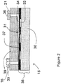
- the flow-through viscosity sensor 15 includes a liquid flow channel 31, with a flow channel entrance 35 and flow channel exit 36 formed in a channel substrate 39.
- the flow channel 31 has a rectangular cross-section with the channel substrate 39 providing three sides of flow channel 31, leaving one open side.
- a monolithic sensor plate 38 formed by a pressure sensor membrane 37 and a pressure sensor substrate 30 is combined with the channel substrate 39 to close the open side of flow channel 31.
- Monolithic sensor plate 38 provides a plurality of independent pressure sensors and is positioned with respect to the channel substrate 39 to locate at least two independent pressure sensors along the flow channel 31 spaced sufficiently away from the channel entrance 35 and channel exit 36 whereby a pressure drop of fully developed flow of liquid through the flow channel 31 can be measured by the pressure sensors.
- each of the independent pressure sensors is formed by a cavity 33 in the pressure sensor membrane 37.
- the portions 34 of the pressure sensor membrane 37 that extend over the respective cavities 33 will deflect into the respective cavities 33 upon application of pressure to such portions 34 of the pressure sensor membrane extending over the respective cavities 33.
- the amount of deflection into a respective cavity is proportional to the pressure applied by the liquid flowing in the flow channel 31 to the pressure sensor membrane over the respective cavities.
- a detector is provided in each of the cavities for detecting the displacement of the membrane into the respective cavity which provides a measurement of the pressure applied to the membrane over the cavity.
- Various detectors can be used, such as a capacitance detector wherein one capacitor electrode is located on the pressure sensor membrane over a cavity and the other capacitor electrode is located on the sensor substrate 30 covering the cavity. Displacement of the membrane moves the capacitor electrodes closer together and changes the capacitance which provides the measure of pressure.
- the surface of the pressure sensor membrane 37 along the liquid channel 31 is substantially a smooth continuous surface without individual pressure sensors being inserted into the surface to form irregularities and discontinuities. This smooth channel surface is important to obtaining accurate pressure measurements.
- Liquid inlet connector 16 attached to channel substrate 39 around liquid channel entrance 35 provides for connection of a source of pressurized sample liquid, here liquid discharged from pipette 14, and liquid outlet connector 21 attached to channel substrate 39 around liquid channel exit 36 provides for connection to a sample liquid drain or holding reservoir.
- Controller 18 includes one or more microcontrollers or microprocessors, and other electrical and electronic components for controlling operation of the viscometer and peripheral components, for performing calculations, for controlling the display 19 which can display the measured viscosity and other information such as status of the viscometer, and for communicating with and transferring data to other equipment such as other computers. Communication can be through ports such as RS232 or USB ports or can be through wireless or other communication means. Controller 18 will generally include interface means, such as a keyboard, touch button pad or key pad, an external computer, or other data entry means such as buttons, a mouse, or a touch screen in display 19, whereby a user can enter control and other instruction and information into the controller.
- interface means such as a keyboard, touch button pad or key pad, an external computer, or other data entry means such as buttons, a mouse, or a touch screen in display 19, whereby a user can enter control and other instruction and information into the controller.
- a sample of the liquid for which the viscosity is to be determined is obtained in a liquid sample holding pipette.
- the sample of liquid in the pipette can have been withdrawn from a source of the liquid into the pipette by the user of the viscometer or can be otherwise supplied to the user of the viscometer in the pipette.
- the pipette 14 is mounted in the viscometer 22 and is held in position in the viscometer by mounting mechanism 28.
- the controller is then activated to control the viscometer to make a viscosity measurement.
- the controller will operate the motor 23 to advance the push back 11 to a position as shown in Fig. 1 against the end 25 of the pipette plunger.
- the push back 11 could be positioned, such as manually, by the user when the pipette is mounted in the viscometer prior to activation of the controller.
- the controller controls the motor 23 so as to rotate lead screw 10 to advance the push back 11 and pipette plunger 12 at a desired speed or speeds to discharge the liquid from the pipette at a known desired flow rate or flow rates.
- the liquid is forced from the pipette into the viscosity sensor 15 and flows through the flow channel 31 in which the pressure drop of a fully developed flow of the liquid is measured by the pressure sensors of the monolithic pressure sensor 38.
- the pressures are measured as the local pressures over respective membrane portions of the pressure sensors along the flow channel 31 deflect sensor membrane portions 34 into respective cavities 33.
- the pressure drop measured along the flow channel 31 (the difference in pressures measured between successive pressure sensors along the flow channel) is proportional to the viscosity of the liquid at the specific flow rate. If the sample viscosity varies with the flow rate, then the control can be instructed to dispense the liquid at different flow rates in sequence, with or without flow stoppage. When the pressure values are acquired and the viscosity values calculated as a function of flow rate, the relationship is corrected for non-Newtonian viscosity in a known manner.
- the measured viscosities may be displayed on the display 19, may be stored in a controller memory or auxiliary memory, and/or transmitted to a remote memory or computer.
- the viscometer senses the pressure inside the liquid flow channel 31.
- the controller is programmed to determine if the pressure level is optimal for the highest accuracy or assured accuracy of the viscosity measurement. If the pressure level is too low, the controller determines and sets the next flow rate value and ramps up the flow rate to the new set value. The controller continues the iteration to reach the optimal flow rate for the particular viscosity measurement. In this way, viscosity of unknown liquids can be accurately and automatically measured.
- the push back 11 is operated to move it back to a position to allow the used pipette to be removed and a new pipette with a sample of new liquid therein for testing to be inserted in the viscometer.
- the pipette with the sample of new liquid to be tested may be a new disposable pipette or a reloaded used pipette.
- the controller operates the viscometer as described above to determine the viscosity of the sample of new liquid. In this test, the liquid from the new sample displaces the liquid from the old sample in the viscosity sensor 15. In this way, no cleaning of the viscosity sensor is needed.
- the viscosity sensor 15 needs to be cleaned with a cleaning liquid compatible to both liquids to be tested prior to dispensing the new liquid into the viscosity sensor 15. This cleaning can be done by loading a pipette containing the cleaning liquid into the viscometer and operating the viscometer to force the cleaning liquid through the viscosity sensor 15 between the two liquids being tested.
- the viscometer 22 may be powered by a battery, such as a rechargeable battery, so that it is truly portable, or may be powered by connecting it to a source of power as it is moved from place to place.
- a battery such as a rechargeable battery
- a temperature control device 50 may be placed in or in contact with pipette mounting mechanism 28 so as to heat or cool a liquid sample holding pipette 14 and the liquid sample contained therein when the pipette is mounted in the mounting mechanism 28.
- the pipette mounting mechanism may also be heated or cooled to the set temperature. Some time may be required for the sample in the pipette to reach the set temperature.
- a temperature control device 52 may be placed in or in contact with the viscosity sensor 15 so as to heat or cool and maintain the temperature of the material forming flow channel 31 of the viscosity sensor 15 at the set temperature. This will tend to maintain the material flowing through the flow channel 31 at substantially the set temperature.
- the temperature control devices may be peltier devices or other known temperature control devices. Further, temperature sensors can be positioned to measure the temperature of the sample liquid at various locations in the viscometer.
- a temperature sensor can be included at one or more locations in the sensor membrane 37 along the flow channel 31 as shown in my prior referenced patents.
- the viscometer 22, or the parts thereof to be temperature controlled may be mounted in a housing where the temperature within the housing, and thus the temperature of the entire viscometer or the parts thereof in the housing, are together temperature controlled.
- the flow-through viscosity sensor described is very small, generally constructed of semiconductor materials or other materials used in microfabrication processes.
- the pressure sensor membrane may be a portion of a silicon wafer, while the pressure sensor substrate and the channel substrate may be portions of a borosilicate glass wafer.
- the flow channel typically can be as small as about ten micrometers in width and about one micrometer in depth, with a length as short as about one hundred micrometers.
- the flow-through viscosity sensor is very small and small sample sizes can be used in determining viscosity.
- This small size of the flow-through viscosity sensor and the small amount of sample needed for viscosity testing means that the other viscometer components, such as the pipettes and the pump can also be made relatively small so the viscometer can easily be made as a relatively small portable unit.
- the same viscometer construction can be used to provide a stationary viscometer where samples of liquid to be tested can be collected from different locations in different pipettes and then transported to the viscometer and tested at the location of the viscometer.
- a database of published or otherwise known viscosity values for liquids frequently measured or that might be measured can be stored in a memory in the viscometer controller.
- a user can easily display a known viscosity value from the database for a selected liquid and compare it to the viscosity value measured for a sample liquid thought to be the known liquid. Discrepancies between the published value and the measured value can indicate that the test liquid is not the liquid it is thought to be or can indicate problems with the viscometer so that the viscometer can be checked.
- the viscometer may store a history of measured viscosity values with appropriate identification, again which may be used by the user of the viscometer for various purposes. For example, with such a history of measured viscosity values, a user can compare the viscosity of a liquid component being used in a manufacturing process at different times to ensure that the liquid component is within specifications required for the liquid component, or can determine and correlate a viscosity value of the component with particular desired attributes of the resulting product.
Landscapes
- Physics & Mathematics (AREA)
- Health & Medical Sciences (AREA)
- Life Sciences & Earth Sciences (AREA)
- Chemical & Material Sciences (AREA)
- Analytical Chemistry (AREA)
- Biochemistry (AREA)
- General Health & Medical Sciences (AREA)
- General Physics & Mathematics (AREA)
- Immunology (AREA)
- Pathology (AREA)
- Sampling And Sample Adjustment (AREA)
- Control Of Positive-Displacement Pumps (AREA)
- Automatic Analysis And Handling Materials Therefor (AREA)
- Coating Apparatus (AREA)
Applications Claiming Priority (2)
| Application Number | Priority Date | Filing Date | Title |
|---|---|---|---|
| US32788910P | 2010-04-26 | 2010-04-26 | |
| PCT/US2011/034002 WO2011139719A2 (en) | 2010-04-26 | 2011-04-26 | Portable viscometer |
Publications (3)
| Publication Number | Publication Date |
|---|---|
| EP2564181A2 EP2564181A2 (en) | 2013-03-06 |
| EP2564181A4 EP2564181A4 (en) | 2017-11-15 |
| EP2564181B1 true EP2564181B1 (en) | 2021-08-25 |
Family
ID=44904345
Family Applications (1)
| Application Number | Title | Priority Date | Filing Date |
|---|---|---|---|
| EP11777928.0A Active EP2564181B1 (en) | 2010-04-26 | 2011-04-26 | Portable viscometer |
Country Status (5)
| Country | Link |
|---|---|
| US (1) | US10451532B2 (enExample) |
| EP (1) | EP2564181B1 (enExample) |
| JP (1) | JP6042803B2 (enExample) |
| CN (2) | CN103080724B (enExample) |
| WO (1) | WO2011139719A2 (enExample) |
Families Citing this family (18)
| Publication number | Priority date | Publication date | Assignee | Title |
|---|---|---|---|---|
| US9389159B2 (en) * | 2008-08-01 | 2016-07-12 | Malvern Instruments Ltd. | Expert-system-based rheology |
| WO2011139719A2 (en) | 2010-04-26 | 2011-11-10 | Rheosense, Inc. | Portable viscometer |
| WO2014031639A1 (en) * | 2012-08-20 | 2014-02-27 | The United States Of America, As Represented By The Secretary, Department Of Health And Humain Services | Capillary viscometer and multiscale pressure differential measuring device |
| EP2972198A4 (en) * | 2013-03-15 | 2016-12-07 | Brookfield Eng Laboratories Inc | MEASURING INSTRUMENT HAVING A TOUCH SCREEN USER INTERFACE AND VISCOSITY MEASURING METHOD |
| USD786279S1 (en) | 2013-03-15 | 2017-05-09 | Brookfield Engineering Laboratories, Inc. | Display screen with graphical user interface for a viscometer or rheometer |
| JP6684214B2 (ja) | 2013-12-09 | 2020-04-22 | テキサス テック ユニヴァーシティー システムTexas Tech University System | 流体の高スループット分析のためのスマートフォンベースの多重化粘度計 |
| JP2017510822A (ja) * | 2014-04-11 | 2017-04-13 | レオセンス,インコーポレイテッド | 粘度計及びその使用方法 |
| CN105675445B (zh) * | 2016-03-25 | 2018-06-05 | 中国石油大学(华东) | 一种高温高压下超临界二氧化碳毛细管粘度计及使用方法 |
| AT518911B1 (de) * | 2016-07-18 | 2022-01-15 | Erema Eng Recycling Maschinen & Anlagen Gmbh | Verfahren und Vorrichtung zur Onlinebestimmung der Viskosität eines Polymers |
| EP3526580B1 (en) * | 2016-10-11 | 2024-03-27 | Rheosense Inc. | Viscometer and methods for using the same |
| CN106525656B (zh) * | 2016-11-30 | 2023-12-12 | 上海大学 | 便携式粘度检测装置 |
| US10144537B2 (en) | 2016-11-30 | 2018-12-04 | Mallinckrodt Nuclear Medicine Llc | Systems and methods for dispensing radioactive liquids |
| WO2018147862A1 (en) | 2017-02-10 | 2018-08-16 | Hewlett-Packard Development Company, L.P. | Determine viscosity of fluids using a capillary channel |
| WO2019060716A1 (en) * | 2017-09-25 | 2019-03-28 | Freenome Holdings, Inc. | SAMPLE EXTRACTION METHODS AND SYSTEMS |
| US10613010B2 (en) * | 2017-12-06 | 2020-04-07 | Ametek, Inc. | Intertial torque device for viscometer calibration and rheology measurements |
| US20210172848A1 (en) * | 2019-12-10 | 2021-06-10 | King Abdullah University Of Science And Technology | Viscosity sensor for real-time monitoring of tubular conduits and method |
| CN111307663A (zh) * | 2020-03-02 | 2020-06-19 | 上海交通大学 | 气体粘度测量装置 |
| US12078582B2 (en) | 2021-05-10 | 2024-09-03 | Rheosense, Inc. | Viscometer with reduced dead-volume and high dynamic range |
Family Cites Families (91)
| Publication number | Priority date | Publication date | Assignee | Title |
|---|---|---|---|---|
| US3143393A (en) * | 1959-06-18 | 1964-08-04 | Luc Donald De Seguin Des Hons | Apparatus for automatically performing chemical operations and similar or related operations |
| US3266299A (en) | 1965-06-14 | 1966-08-16 | Roy L Swank | Constant flow pressure filter apparatus |
| US3683678A (en) * | 1971-05-03 | 1972-08-15 | Du Pont | Method and apparatus for molecular weight measurement |
| DE2444148C3 (de) * | 1974-09-16 | 1981-09-17 | Dr. Karl Thomae Gmbh, 7950 Biberach | Kapillar-Viskosimeter |
| US4122708A (en) | 1976-03-31 | 1978-10-31 | Simmonds Precision Products, Inc. | Capacitive proximity sensors |
| US4141252A (en) * | 1977-11-04 | 1979-02-27 | Lodge Arthur S | Flush pressure transducers for measuring pressures in a flowing fluid |
| FI57542C (fi) | 1978-06-02 | 1980-09-10 | Suovaniemi Finnpipette | Volymreglerbar pipett |
| US4241602A (en) | 1979-04-20 | 1980-12-30 | Seismograph Service Corporation | Rheometer |
| US4916678A (en) | 1979-06-29 | 1990-04-10 | Phillips Petroleum Company | Viscometer |
| JPS56157839A (en) | 1980-05-09 | 1981-12-05 | Japan Synthetic Rubber Co Ltd | Slit die type rheometer |
| JPS5745430A (en) | 1980-09-02 | 1982-03-15 | Japan Synthetic Rubber Co Ltd | Slit die rheometer |
| US4422210A (en) | 1980-11-12 | 1983-12-27 | Goteborgs Maskinkonsult Aktiebolag | Installation for internal cleaning of tubes |
| FI62470C (fi) | 1981-06-17 | 1983-01-10 | Labsystems Oy | Pipett |
| JPS5888637A (ja) | 1981-11-21 | 1983-05-26 | Japan Synthetic Rubber Co Ltd | ダイレオメ−タ |
| US4574622A (en) * | 1984-03-27 | 1986-03-11 | Union Carbide Corporation | Viscometer |
| GB2158252B (en) | 1984-04-12 | 1988-08-24 | John Parnaby | Pheometer |
| JPS61107251A (ja) | 1984-10-31 | 1986-05-26 | Canon Inc | 電子写真感光体 |
| JPS61190853A (ja) | 1985-02-18 | 1986-08-25 | 松下電子工業株式会社 | 白熱電球 |
| JPS61190853U (enExample) * | 1985-05-21 | 1986-11-27 | ||
| DE3635462A1 (de) | 1985-10-21 | 1987-04-23 | Sharp Kk | Feldeffekt-drucksensor |
| AT396998B (de) | 1985-12-09 | 1994-01-25 | Ottosensors Corp | Messeinrichtungen und rohranschluss sowie verfahren zur herstellung einer messeinrichtung und verfahren zur verbindung von rohren mit einer messeinrichtung bzw. zur herstellung von rohranschlüssen |
| DE3771513D1 (de) | 1986-01-29 | 1991-08-29 | Marukomu Kk | Rotationsviskosimeter. |
| JPH0654287B2 (ja) | 1986-02-21 | 1994-07-20 | 日本鋼管株式会社 | パイプラインにおける非ニユ−トン性の測定装置 |
| ES2033001T3 (es) | 1987-06-12 | 1993-03-01 | Juerg Dual | Viscosimetro |
| US4874500A (en) | 1987-07-15 | 1989-10-17 | Sri International | Microelectrochemical sensor and sensor array |
| US4793174A (en) * | 1987-10-05 | 1988-12-27 | E. I. Du Pont De Nemours And Company | Differential pressure capillary viscometer |
| US5029479A (en) | 1988-08-15 | 1991-07-09 | Imo Industries, Inc. | Differential pressure transducers |
| US5058435A (en) | 1989-06-22 | 1991-10-22 | Ic Sensors, Inc. | Single diaphragm transducer with multiple sensing elements |
| US5189777A (en) | 1990-12-07 | 1993-03-02 | Wisconsin Alumni Research Foundation | Method of producing micromachined differential pressure transducers |
| US5347851A (en) * | 1991-04-04 | 1994-09-20 | Dynisco, Inc. | Capillary rheometer plunger pressure transducer and measurement technique |
| JP2582003B2 (ja) * | 1991-05-22 | 1997-02-19 | 本田技研工業株式会社 | 圧力機器用圧力源 |
| US5225959A (en) | 1991-10-15 | 1993-07-06 | Xerox Corporation | Capacitive tactile sensor array and method for sensing pressure with the array |
| JP3203560B2 (ja) | 1991-12-13 | 2001-08-27 | ハネウエル・インコーポレーテッド | 圧電抵抗シリコン圧力センサ設計 |
| US5317908A (en) | 1992-04-28 | 1994-06-07 | National Metal Refining Company, Inc. | High viscosity transducer for vibratory viscometer |
| US5304487A (en) | 1992-05-01 | 1994-04-19 | Trustees Of The University Of Pennsylvania | Fluid handling in mesoscale analytical devices |
| US5486335A (en) | 1992-05-01 | 1996-01-23 | Trustees Of The University Of Pennsylvania | Analysis based on flow restriction |
| JP3262373B2 (ja) * | 1992-06-30 | 2002-03-04 | 株式会社東芝 | 流動抵抗評価方法及びその装置 |
| CA2074289C (en) | 1992-07-21 | 1999-09-14 | Claude Belleville | Fabry-perot optical sensing device for measuring a physical parameter |
| JPH06201420A (ja) | 1992-12-28 | 1994-07-19 | Fujikura Ltd | 流量センサおよびその製造方法 |
| DE4330562A1 (de) | 1993-09-09 | 1995-03-16 | Behringwerke Ag | Kunststoffpipette |
| US5388447A (en) * | 1993-11-26 | 1995-02-14 | Diagnetics, Inc. | Viscosity measurement apparatus |
| US5602339A (en) | 1994-03-24 | 1997-02-11 | Dynisco, Inc. | Injection molding machine pressure transducer with trapezoidal cavity |
| US5503003A (en) | 1994-12-14 | 1996-04-02 | Brookfield Engineering Laboratories, Inc. | Portable viscometer |
| CA2145599C (en) | 1995-03-27 | 2001-12-04 | David Wesley Forbes | Method of continuously testing the accuracy of results obtained from an automatic viscometer |
| US5663503A (en) | 1995-09-08 | 1997-09-02 | Cosense, Inc. | Invasive and non-invasive ultrasonic sensor with continuous and demand self-test |
| CA2185292A1 (en) * | 1995-09-15 | 1997-03-16 | James C. Smith | Positive displacement liquid drawing and dispensing apparatus and method |
| DE19614458C2 (de) | 1996-04-12 | 1998-10-29 | Grundfos As | Druck- oder Differenzdrucksensor und Verfahren zu seiner Herstellung |
| WO1997039320A1 (de) | 1996-04-13 | 1997-10-23 | Robert Bosch Gmbh | Drucksensor |
| US5877409A (en) * | 1997-06-06 | 1999-03-02 | Mobil Oil Corporation | Method and system for determining viscosity index |
| EP0884578A3 (en) * | 1997-06-09 | 1999-09-22 | Dickey-John Corporation | Portable viscometer with crystal resonator-type sensor |
| US5983727A (en) | 1997-08-19 | 1999-11-16 | Pressure Profile Systems | System generating a pressure profile across a pressure sensitive membrane |
| DE19750131C2 (de) | 1997-11-13 | 2002-06-13 | Infineon Technologies Ag | Mikromechanische Differenzdrucksensorvorrichtung |
| JP3873084B2 (ja) | 1997-12-29 | 2007-01-24 | 財団法人くまもとテクノ産業財団 | 動粘度計 |
| US6237398B1 (en) | 1997-12-30 | 2001-05-29 | Remon Medical Technologies, Ltd. | System and method for monitoring pressure, flow and constriction parameters of plumbing and blood vessels |
| JPH11248715A (ja) * | 1998-03-06 | 1999-09-17 | Matsushita Electric Ind Co Ltd | 分注ヘッドおよび分注チップ |
| US6010461A (en) | 1998-09-01 | 2000-01-04 | Sitek, Inc. | Monolithic silicon intra-ocular pressure sensor and method therefor |
| US6078706A (en) | 1998-09-22 | 2000-06-20 | The United States Of America As Represented By The Secretary Of The Navy | Quasi-static fiber pressure sensor |
| US6032689A (en) | 1998-10-30 | 2000-03-07 | Industrial Technology Research Institute | Integrated flow controller module |
| US6216528B1 (en) * | 1998-12-15 | 2001-04-17 | Caterpillar Inc. | Method and apparatus for determining a viscosity of an actuating fluid |
| US6338284B1 (en) | 1999-02-12 | 2002-01-15 | Integrated Sensing Systems (Issys) Inc. | Electrical feedthrough structures for micromachined devices and methods of fabricating the same |
| DE19911441B4 (de) | 1999-03-04 | 2011-04-07 | Anton Paar Gmbh | Rheometer bzw. Rotationsviskosimeter |
| AT409304B (de) | 1999-09-24 | 2002-07-25 | Anton Paar Gmbh | Rotationsrheometer |
| US6575019B1 (en) | 2000-01-14 | 2003-06-10 | Chandler Engineering Company Llc | Reciprocating drive/pump system and reciprocating capillary viscometer utilizing same |
| GB0002192D0 (en) | 2000-01-31 | 2000-03-22 | Borealis Polymers Oy | Rheometry |
| AU2001249071B2 (en) * | 2000-02-23 | 2005-09-08 | Caliper Life Sciences, Inc. | Multi-reservoir pressure control system |
| US6681616B2 (en) * | 2000-02-23 | 2004-01-27 | Caliper Technologies Corp. | Microfluidic viscometer |
| US6553812B2 (en) | 2000-05-02 | 2003-04-29 | Kavlico Corporation | Combined oil quality and viscosity sensing system |
| US6393898B1 (en) * | 2000-05-25 | 2002-05-28 | Symyx Technologies, Inc. | High throughput viscometer and method of using same |
| US7223363B2 (en) | 2001-03-09 | 2007-05-29 | Biomicro Systems, Inc. | Method and system for microfluidic interfacing to arrays |
| US7290441B2 (en) * | 2001-10-31 | 2007-11-06 | Rheosense, Inc. | Micro slit viscometer with monolithically integrated pressure sensors |
| US6892583B2 (en) | 2001-10-31 | 2005-05-17 | Rheosense, Inc. | Pressure sensing device for rheometers |
| US7770436B2 (en) | 2001-10-31 | 2010-08-10 | Rheosense, Inc. | Micro rheometer for measuring flow viscosity and elasticity for micron sample volumes |
| DE10215946B4 (de) | 2002-04-11 | 2004-02-26 | Krauss-Maffei Kunststofftechnik Gmbh | Rheologische Messeinrichtung für eine Spritzgießmaschine |
| GB0217494D0 (en) | 2002-07-29 | 2002-09-04 | Boc Group Plc | Conditioning monitoring of pumps and pump systems |
| WO2005086883A2 (en) | 2004-03-11 | 2005-09-22 | Rheosense, Inc. | Micro slit viscometer with monolithically integrated pressure sesonrs |
| JP4602162B2 (ja) * | 2004-06-15 | 2010-12-22 | セイコーインスツル株式会社 | マイクロチップシステム |
| US9477233B2 (en) | 2004-07-02 | 2016-10-25 | The University Of Chicago | Microfluidic system with a plurality of sequential T-junctions for performing reactions in microdroplets |
| DE602005022196D1 (de) | 2004-07-23 | 2010-08-19 | Biosystem Dev Llc | Vorrichtung für einen immunoassay und verfahren zu ihrer verwendung |
| WO2006039513A1 (en) | 2004-10-01 | 2006-04-13 | Halliburton Energy Services, Inc. | Method and apparatus for acquiring physical properties of fluid samples |
| JP4657803B2 (ja) * | 2005-05-19 | 2011-03-23 | 富士フイルム株式会社 | 送液システム及びその送液方法並びに流路ユニット。 |
| US7730769B1 (en) | 2006-05-24 | 2010-06-08 | Kwon Kyung C | Capillary viscometers for use with Newtonian and non-Newtonian fluids |
| US7558255B2 (en) * | 2006-07-13 | 2009-07-07 | Alcatel-Lucent Usa Inc. | Method of switching modes of uplink transmission in a wireless communication system |
| US20080125700A1 (en) * | 2006-11-29 | 2008-05-29 | Moberg Sheldon B | Methods and apparatuses for detecting medical device acceleration, temperature, and humidity conditions |
| US20090004063A1 (en) | 2007-06-29 | 2009-01-01 | Symyx Technologies, Inc. | Apparatus and method for actuating a syringe |
| FR2927999B1 (fr) * | 2008-02-21 | 2010-09-17 | Gilson Sas | Viscosimetre comprenant un systeme de pipetage, a precision amelioree et conception simplifiee |
| US8230723B2 (en) | 2008-09-19 | 2012-07-31 | Chandler Instruments Company, LLC | High pressure high temperature viscometer |
| JP4706883B2 (ja) | 2009-03-17 | 2011-06-22 | セイコーエプソン株式会社 | 生体試料定量方法 |
| CN102460112B (zh) | 2009-03-24 | 2015-04-08 | 诺克罗斯公司 | 用于粘度计的混合器以及使用所述混合器的方法及计算机可读媒体 |
| WO2011139719A2 (en) | 2010-04-26 | 2011-11-10 | Rheosense, Inc. | Portable viscometer |
| WO2014031639A1 (en) | 2012-08-20 | 2014-02-27 | The United States Of America, As Represented By The Secretary, Department Of Health And Humain Services | Capillary viscometer and multiscale pressure differential measuring device |
| JP2017510822A (ja) | 2014-04-11 | 2017-04-13 | レオセンス,インコーポレイテッド | 粘度計及びその使用方法 |
-
2011
- 2011-04-26 WO PCT/US2011/034002 patent/WO2011139719A2/en not_active Ceased
- 2011-04-26 US US13/094,710 patent/US10451532B2/en active Active
- 2011-04-26 EP EP11777928.0A patent/EP2564181B1/en active Active
- 2011-04-26 CN CN201180031161.1A patent/CN103080724B/zh active Active
- 2011-04-26 CN CN201610164123.8A patent/CN105784547B/zh active Active
- 2011-04-26 JP JP2013508172A patent/JP6042803B2/ja active Active
Non-Patent Citations (1)
| Title |
|---|
| None * |
Also Published As
| Publication number | Publication date |
|---|---|
| CN103080724A (zh) | 2013-05-01 |
| EP2564181A2 (en) | 2013-03-06 |
| CN105784547A (zh) | 2016-07-20 |
| WO2011139719A2 (en) | 2011-11-10 |
| US10451532B2 (en) | 2019-10-22 |
| US20120096929A1 (en) | 2012-04-26 |
| JP6042803B2 (ja) | 2016-12-14 |
| CN103080724B (zh) | 2016-04-13 |
| WO2011139719A8 (en) | 2012-04-05 |
| EP2564181A4 (en) | 2017-11-15 |
| JP2013525799A (ja) | 2013-06-20 |
| CN105784547B (zh) | 2019-11-05 |
| WO2011139719A3 (en) | 2012-05-31 |
Similar Documents
| Publication | Publication Date | Title |
|---|---|---|
| EP2564181B1 (en) | Portable viscometer | |
| US12372451B2 (en) | Viscometer and methods for using the same | |
| US7188515B2 (en) | Nanoliter viscometer for analyzing blood plasma and other liquid samples | |
| JP2013525799A5 (enExample) | ||
| JP4719692B2 (ja) | ピペット検査装置及びそれを取り付けたピペット | |
| US20220357258A1 (en) | Viscometer with reduced dead-volume and high dynamic range | |
| EP3526580B1 (en) | Viscometer and methods for using the same | |
| US7681437B2 (en) | Device for determining the viscosity of fluids | |
| Cavallaro et al. | Picoliter fluidic flow characterization using ion-selective measurement |
Legal Events
| Date | Code | Title | Description |
|---|---|---|---|
| PUAI | Public reference made under article 153(3) epc to a published international application that has entered the european phase |
Free format text: ORIGINAL CODE: 0009012 |
|
| 17P | Request for examination filed |
Effective date: 20121126 |
|
| AK | Designated contracting states |
Kind code of ref document: A2 Designated state(s): AL AT BE BG CH CY CZ DE DK EE ES FI FR GB GR HR HU IE IS IT LI LT LU LV MC MK MT NL NO PL PT RO RS SE SI SK SM TR |
|
| DAX | Request for extension of the european patent (deleted) | ||
| A4 | Supplementary search report drawn up and despatched |
Effective date: 20171018 |
|
| RIC1 | Information provided on ipc code assigned before grant |
Ipc: G01N 11/08 20060101AFI20171012BHEP |
|
| STAA | Information on the status of an ep patent application or granted ep patent |
Free format text: STATUS: EXAMINATION IS IN PROGRESS |
|
| 17Q | First examination report despatched |
Effective date: 20191022 |
|
| GRAP | Despatch of communication of intention to grant a patent |
Free format text: ORIGINAL CODE: EPIDOSNIGR1 |
|
| STAA | Information on the status of an ep patent application or granted ep patent |
Free format text: STATUS: GRANT OF PATENT IS INTENDED |
|
| INTG | Intention to grant announced |
Effective date: 20210331 |
|
| GRAS | Grant fee paid |
Free format text: ORIGINAL CODE: EPIDOSNIGR3 |
|
| GRAA | (expected) grant |
Free format text: ORIGINAL CODE: 0009210 |
|
| STAA | Information on the status of an ep patent application or granted ep patent |
Free format text: STATUS: THE PATENT HAS BEEN GRANTED |
|
| AK | Designated contracting states |
Kind code of ref document: B1 Designated state(s): AL AT BE BG CH CY CZ DE DK EE ES FI FR GB GR HR HU IE IS IT LI LT LU LV MC MK MT NL NO PL PT RO RS SE SI SK SM TR |
|
| REG | Reference to a national code |
Ref country code: GB Ref legal event code: FG4D |
|
| REG | Reference to a national code |
Ref country code: CH Ref legal event code: EP |
|
| REG | Reference to a national code |
Ref country code: DE Ref legal event code: R096 Ref document number: 602011071647 Country of ref document: DE |
|
| REG | Reference to a national code |
Ref country code: IE Ref legal event code: FG4D Ref country code: AT Ref legal event code: REF Ref document number: 1424284 Country of ref document: AT Kind code of ref document: T Effective date: 20210915 |
|
| REG | Reference to a national code |
Ref country code: LT Ref legal event code: MG9D |
|
| REG | Reference to a national code |
Ref country code: NL Ref legal event code: MP Effective date: 20210825 |
|
| REG | Reference to a national code |
Ref country code: AT Ref legal event code: MK05 Ref document number: 1424284 Country of ref document: AT Kind code of ref document: T Effective date: 20210825 |
|
| PG25 | Lapsed in a contracting state [announced via postgrant information from national office to epo] |
Ref country code: FI Free format text: LAPSE BECAUSE OF FAILURE TO SUBMIT A TRANSLATION OF THE DESCRIPTION OR TO PAY THE FEE WITHIN THE PRESCRIBED TIME-LIMIT Effective date: 20210825 Ref country code: ES Free format text: LAPSE BECAUSE OF FAILURE TO SUBMIT A TRANSLATION OF THE DESCRIPTION OR TO PAY THE FEE WITHIN THE PRESCRIBED TIME-LIMIT Effective date: 20210825 Ref country code: RS Free format text: LAPSE BECAUSE OF FAILURE TO SUBMIT A TRANSLATION OF THE DESCRIPTION OR TO PAY THE FEE WITHIN THE PRESCRIBED TIME-LIMIT Effective date: 20210825 Ref country code: NO Free format text: LAPSE BECAUSE OF FAILURE TO SUBMIT A TRANSLATION OF THE DESCRIPTION OR TO PAY THE FEE WITHIN THE PRESCRIBED TIME-LIMIT Effective date: 20211125 Ref country code: PT Free format text: LAPSE BECAUSE OF FAILURE TO SUBMIT A TRANSLATION OF THE DESCRIPTION OR TO PAY THE FEE WITHIN THE PRESCRIBED TIME-LIMIT Effective date: 20211227 Ref country code: LT Free format text: LAPSE BECAUSE OF FAILURE TO SUBMIT A TRANSLATION OF THE DESCRIPTION OR TO PAY THE FEE WITHIN THE PRESCRIBED TIME-LIMIT Effective date: 20210825 Ref country code: AT Free format text: LAPSE BECAUSE OF FAILURE TO SUBMIT A TRANSLATION OF THE DESCRIPTION OR TO PAY THE FEE WITHIN THE PRESCRIBED TIME-LIMIT Effective date: 20210825 Ref country code: BG Free format text: LAPSE BECAUSE OF FAILURE TO SUBMIT A TRANSLATION OF THE DESCRIPTION OR TO PAY THE FEE WITHIN THE PRESCRIBED TIME-LIMIT Effective date: 20211125 Ref country code: SE Free format text: LAPSE BECAUSE OF FAILURE TO SUBMIT A TRANSLATION OF THE DESCRIPTION OR TO PAY THE FEE WITHIN THE PRESCRIBED TIME-LIMIT Effective date: 20210825 Ref country code: HR Free format text: LAPSE BECAUSE OF FAILURE TO SUBMIT A TRANSLATION OF THE DESCRIPTION OR TO PAY THE FEE WITHIN THE PRESCRIBED TIME-LIMIT Effective date: 20210825 |
|
| PG25 | Lapsed in a contracting state [announced via postgrant information from national office to epo] |
Ref country code: PL Free format text: LAPSE BECAUSE OF FAILURE TO SUBMIT A TRANSLATION OF THE DESCRIPTION OR TO PAY THE FEE WITHIN THE PRESCRIBED TIME-LIMIT Effective date: 20210825 Ref country code: LV Free format text: LAPSE BECAUSE OF FAILURE TO SUBMIT A TRANSLATION OF THE DESCRIPTION OR TO PAY THE FEE WITHIN THE PRESCRIBED TIME-LIMIT Effective date: 20210825 Ref country code: GR Free format text: LAPSE BECAUSE OF FAILURE TO SUBMIT A TRANSLATION OF THE DESCRIPTION OR TO PAY THE FEE WITHIN THE PRESCRIBED TIME-LIMIT Effective date: 20211126 |
|
| PG25 | Lapsed in a contracting state [announced via postgrant information from national office to epo] |
Ref country code: NL Free format text: LAPSE BECAUSE OF FAILURE TO SUBMIT A TRANSLATION OF THE DESCRIPTION OR TO PAY THE FEE WITHIN THE PRESCRIBED TIME-LIMIT Effective date: 20210825 |
|
| PG25 | Lapsed in a contracting state [announced via postgrant information from national office to epo] |
Ref country code: DK Free format text: LAPSE BECAUSE OF FAILURE TO SUBMIT A TRANSLATION OF THE DESCRIPTION OR TO PAY THE FEE WITHIN THE PRESCRIBED TIME-LIMIT Effective date: 20210825 |
|
| REG | Reference to a national code |
Ref country code: DE Ref legal event code: R097 Ref document number: 602011071647 Country of ref document: DE |
|
| PG25 | Lapsed in a contracting state [announced via postgrant information from national office to epo] |
Ref country code: SM Free format text: LAPSE BECAUSE OF FAILURE TO SUBMIT A TRANSLATION OF THE DESCRIPTION OR TO PAY THE FEE WITHIN THE PRESCRIBED TIME-LIMIT Effective date: 20210825 Ref country code: SK Free format text: LAPSE BECAUSE OF FAILURE TO SUBMIT A TRANSLATION OF THE DESCRIPTION OR TO PAY THE FEE WITHIN THE PRESCRIBED TIME-LIMIT Effective date: 20210825 Ref country code: RO Free format text: LAPSE BECAUSE OF FAILURE TO SUBMIT A TRANSLATION OF THE DESCRIPTION OR TO PAY THE FEE WITHIN THE PRESCRIBED TIME-LIMIT Effective date: 20210825 Ref country code: EE Free format text: LAPSE BECAUSE OF FAILURE TO SUBMIT A TRANSLATION OF THE DESCRIPTION OR TO PAY THE FEE WITHIN THE PRESCRIBED TIME-LIMIT Effective date: 20210825 Ref country code: CZ Free format text: LAPSE BECAUSE OF FAILURE TO SUBMIT A TRANSLATION OF THE DESCRIPTION OR TO PAY THE FEE WITHIN THE PRESCRIBED TIME-LIMIT Effective date: 20210825 Ref country code: AL Free format text: LAPSE BECAUSE OF FAILURE TO SUBMIT A TRANSLATION OF THE DESCRIPTION OR TO PAY THE FEE WITHIN THE PRESCRIBED TIME-LIMIT Effective date: 20210825 |
|
| PLBE | No opposition filed within time limit |
Free format text: ORIGINAL CODE: 0009261 |
|
| STAA | Information on the status of an ep patent application or granted ep patent |
Free format text: STATUS: NO OPPOSITION FILED WITHIN TIME LIMIT |
|
| PG25 | Lapsed in a contracting state [announced via postgrant information from national office to epo] |
Ref country code: IT Free format text: LAPSE BECAUSE OF FAILURE TO SUBMIT A TRANSLATION OF THE DESCRIPTION OR TO PAY THE FEE WITHIN THE PRESCRIBED TIME-LIMIT Effective date: 20210825 |
|
| 26N | No opposition filed |
Effective date: 20220527 |
|
| PG25 | Lapsed in a contracting state [announced via postgrant information from national office to epo] |
Ref country code: SI Free format text: LAPSE BECAUSE OF FAILURE TO SUBMIT A TRANSLATION OF THE DESCRIPTION OR TO PAY THE FEE WITHIN THE PRESCRIBED TIME-LIMIT Effective date: 20210825 |
|
| REG | Reference to a national code |
Ref country code: CH Ref legal event code: PL |
|
| REG | Reference to a national code |
Ref country code: BE Ref legal event code: MM Effective date: 20220430 |
|
| PG25 | Lapsed in a contracting state [announced via postgrant information from national office to epo] |
Ref country code: MC Free format text: LAPSE BECAUSE OF FAILURE TO SUBMIT A TRANSLATION OF THE DESCRIPTION OR TO PAY THE FEE WITHIN THE PRESCRIBED TIME-LIMIT Effective date: 20210825 Ref country code: LU Free format text: LAPSE BECAUSE OF NON-PAYMENT OF DUE FEES Effective date: 20220426 Ref country code: LI Free format text: LAPSE BECAUSE OF NON-PAYMENT OF DUE FEES Effective date: 20220430 Ref country code: CH Free format text: LAPSE BECAUSE OF NON-PAYMENT OF DUE FEES Effective date: 20220430 |
|
| PG25 | Lapsed in a contracting state [announced via postgrant information from national office to epo] |
Ref country code: BE Free format text: LAPSE BECAUSE OF NON-PAYMENT OF DUE FEES Effective date: 20220430 |
|
| PG25 | Lapsed in a contracting state [announced via postgrant information from national office to epo] |
Ref country code: IE Free format text: LAPSE BECAUSE OF NON-PAYMENT OF DUE FEES Effective date: 20220426 |
|
| P01 | Opt-out of the competence of the unified patent court (upc) registered |
Effective date: 20230602 |
|
| PG25 | Lapsed in a contracting state [announced via postgrant information from national office to epo] |
Ref country code: HU Free format text: LAPSE BECAUSE OF FAILURE TO SUBMIT A TRANSLATION OF THE DESCRIPTION OR TO PAY THE FEE WITHIN THE PRESCRIBED TIME-LIMIT; INVALID AB INITIO Effective date: 20110426 |
|
| PG25 | Lapsed in a contracting state [announced via postgrant information from national office to epo] |
Ref country code: MK Free format text: LAPSE BECAUSE OF FAILURE TO SUBMIT A TRANSLATION OF THE DESCRIPTION OR TO PAY THE FEE WITHIN THE PRESCRIBED TIME-LIMIT Effective date: 20210825 Ref country code: CY Free format text: LAPSE BECAUSE OF FAILURE TO SUBMIT A TRANSLATION OF THE DESCRIPTION OR TO PAY THE FEE WITHIN THE PRESCRIBED TIME-LIMIT Effective date: 20210825 |
|
| PG25 | Lapsed in a contracting state [announced via postgrant information from national office to epo] |
Ref country code: TR Free format text: LAPSE BECAUSE OF FAILURE TO SUBMIT A TRANSLATION OF THE DESCRIPTION OR TO PAY THE FEE WITHIN THE PRESCRIBED TIME-LIMIT Effective date: 20210825 |
|
| PG25 | Lapsed in a contracting state [announced via postgrant information from national office to epo] |
Ref country code: MT Free format text: LAPSE BECAUSE OF FAILURE TO SUBMIT A TRANSLATION OF THE DESCRIPTION OR TO PAY THE FEE WITHIN THE PRESCRIBED TIME-LIMIT Effective date: 20210825 |
|
| PGFP | Annual fee paid to national office [announced via postgrant information from national office to epo] |
Ref country code: DE Payment date: 20250416 Year of fee payment: 15 |
|
| PGFP | Annual fee paid to national office [announced via postgrant information from national office to epo] |
Ref country code: GB Payment date: 20250423 Year of fee payment: 15 |
|
| PGFP | Annual fee paid to national office [announced via postgrant information from national office to epo] |
Ref country code: FR Payment date: 20250422 Year of fee payment: 15 |