EP2563711B1 - Distributeur à bouton-poussoir pour bouteilles contenant des boissons gazéifiées - Google Patents
Distributeur à bouton-poussoir pour bouteilles contenant des boissons gazéifiées Download PDFInfo
- Publication number
- EP2563711B1 EP2563711B1 EP11717559.6A EP11717559A EP2563711B1 EP 2563711 B1 EP2563711 B1 EP 2563711B1 EP 11717559 A EP11717559 A EP 11717559A EP 2563711 B1 EP2563711 B1 EP 2563711B1
- Authority
- EP
- European Patent Office
- Prior art keywords
- push
- bottle
- dispenser
- suction tube
- button
- Prior art date
- Legal status (The legal status is an assumption and is not a legal conclusion. Google has not performed a legal analysis and makes no representation as to the accuracy of the status listed.)
- Not-in-force
Links
Images


Classifications
-
- B—PERFORMING OPERATIONS; TRANSPORTING
- B65—CONVEYING; PACKING; STORING; HANDLING THIN OR FILAMENTARY MATERIAL
- B65D—CONTAINERS FOR STORAGE OR TRANSPORT OF ARTICLES OR MATERIALS, e.g. BAGS, BARRELS, BOTTLES, BOXES, CANS, CARTONS, CRATES, DRUMS, JARS, TANKS, HOPPERS, FORWARDING CONTAINERS; ACCESSORIES, CLOSURES, OR FITTINGS THEREFOR; PACKAGING ELEMENTS; PACKAGES
- B65D47/00—Closures with filling and discharging, or with discharging, devices
- B65D47/04—Closures with discharging devices other than pumps
- B65D47/06—Closures with discharging devices other than pumps with pouring spouts or tubes; with discharge nozzles or passages
- B65D47/10—Closures with discharging devices other than pumps with pouring spouts or tubes; with discharge nozzles or passages having frangible closures
- B65D47/103—Membranes with a tearing element
-
- B—PERFORMING OPERATIONS; TRANSPORTING
- B65—CONVEYING; PACKING; STORING; HANDLING THIN OR FILAMENTARY MATERIAL
- B65D—CONTAINERS FOR STORAGE OR TRANSPORT OF ARTICLES OR MATERIALS, e.g. BAGS, BARRELS, BOTTLES, BOXES, CANS, CARTONS, CRATES, DRUMS, JARS, TANKS, HOPPERS, FORWARDING CONTAINERS; ACCESSORIES, CLOSURES, OR FITTINGS THEREFOR; PACKAGING ELEMENTS; PACKAGES
- B65D83/00—Containers or packages with special means for dispensing contents
- B65D83/14—Containers or packages with special means for dispensing contents for delivery of liquid or semi-liquid contents by internal gaseous pressure, i.e. aerosol containers comprising propellant for a product delivered by a propellant
- B65D83/32—Dip-tubes
-
- B—PERFORMING OPERATIONS; TRANSPORTING
- B65—CONVEYING; PACKING; STORING; HANDLING THIN OR FILAMENTARY MATERIAL
- B65D—CONTAINERS FOR STORAGE OR TRANSPORT OF ARTICLES OR MATERIALS, e.g. BAGS, BARRELS, BOTTLES, BOXES, CANS, CARTONS, CRATES, DRUMS, JARS, TANKS, HOPPERS, FORWARDING CONTAINERS; ACCESSORIES, CLOSURES, OR FITTINGS THEREFOR; PACKAGING ELEMENTS; PACKAGES
- B65D83/00—Containers or packages with special means for dispensing contents
- B65D83/14—Containers or packages with special means for dispensing contents for delivery of liquid or semi-liquid contents by internal gaseous pressure, i.e. aerosol containers comprising propellant for a product delivered by a propellant
- B65D83/44—Valves specially adapted therefor; Regulating devices
-
- B—PERFORMING OPERATIONS; TRANSPORTING
- B67—OPENING, CLOSING OR CLEANING BOTTLES, JARS OR SIMILAR CONTAINERS; LIQUID HANDLING
- B67D—DISPENSING, DELIVERING OR TRANSFERRING LIQUIDS, NOT OTHERWISE PROVIDED FOR
- B67D1/00—Apparatus or devices for dispensing beverages on draught
- B67D1/04—Apparatus utilising compressed air or other gas acting directly or indirectly on beverages in storage containers
- B67D1/0456—Siphons, i.e. beverage containers under gas pressure without supply of further pressurised gas during dispensing
Definitions
- This invention relates to a dispenser for dispensing a carbonated beverage from a bottle by a simple push of a button, whether the bottle is standing or lying down.
- Carbonated drinks are sold in glass and pet bottles as well as in aluminum cans in very large numbers. Every day many millions of such bottles are opened and the contents are poured out and drunk. The carbon dioxide in the drink, which gives the same freshness, caused by their outgassing pressure increase in the bottle. Everybody is familiar with the pffffft sound, which can be heard when opening such a bottle, because a certain overpressure in the bottle first escapes.
- the bottles are available in different sizes, with 0.33 liter, 0.5, 1, 1.5, 2 liter content up to 3 liter bottles. However, larger bottles are not easy to handle for all people. Especially smaller children as well as weak or elderly people are struggling with the handling of heavy bottles.
- the bottles are often stored in a refrigerator and if a drink is desired, the bottle must be removed from the refrigerator, opened, raised to pour and tilted over a drinking cup and then re-supplied in the refrigerator. These steps can be laborious or even impossible to accomplish for small children or for debilitated adults - such as the sick or old or handicapped people.
- the initial opening of the threaded closure which is also provided with a guarantee strip, which must be broken when opening, requires some effort, which can not be applied by all.
- the repeated opening and closing of such a beverage bottle leads to the escape of a portion of the carbon dioxide, so that the drink stale
- Figure 1 shows a device with a dispensing valve and a separate carbon dioxide valve to add carbon dioxide into the bottle when its internal pressure drops below a certain level.
- a pressure regulator is disclosed to regulate the carbon dioxide pressure in the beverage. But not only the pressure drop when dispensing carbonated bottle contents, which usually prevents a complete emptying, is a problem.
- GB 2 219 988 shows a dispenser, which can be screwed onto a bottle.
- a tube leads down to the bottom of the bottle.
- a manually operated, spring-loaded valve reduces the pressure in the outlet by opening the compressed tube at a location very close to the spout to controllably dispense the beverage from the bottle due to the increased internal pressure.
- the dispenser also includes a pressure regulator with a CO 2 pressure capsule from which CO 2 is added when the internal pressure of the bottle falls below a certain level.
- this dispenser consists of a very large number of parts, including metallic parts, and it is correspondingly expensive to manufacture and assemble.
- dispensers which can be subsequently screwed onto a bottle. However, a first, substantial portion of carbon dioxide will already escape through the first opening of the bottle, just to screw the dispenser onto the bottle. On the other hand, such dispensers are only rarely used - if at all.
- the pressure control device has an axially movable control element, which is acted upon by a biasing means, so that it is kept closed becomes.
- the internal pressure acts on the control element in the closing direction.
- the ambient pressure acts on the control element in the direction of its open position.
- a new dispenser can not concern only the basic principle of the function, which is well-known, but rather only a specific embodiment of such a dispenser and a specific implementation of this basic principle, so that this technically better and easier implemented, and also in such a way, which makes such a dispenser to a very cost-effective, but reliable functioning and extremely easy to use mass product. All this is the basic requirement that such a dispenser gets a chance to survive in the market.
- a push-button dispenser for bottles with carbonated drinks with a screwable on a bottle head with side spout, push button on its top and downwardly projecting suction tube, which is intended to reach down to the bottom of the bottle to be equipped, and above opens into a valve device in the head, which has a with respect to the bottle axially movable control member, which is acted upon by a spring in the closing direction, and the opening from above by hand with pressure on the push button can be acted upon, so that the pressure in the interior of the suction tube can be reduced to ambient pressure, whereby liquid from the bottle by the prevailing internal pressure in the bottle from the lower mouth of the suction pipe via the spout can be driven
- this pressure button dispenser is characterized in that the suction tube is made of a rubber-elastic plastic and be Outside and inside cross-section are designed so that it can be narrowed at reduced to ambient pressure internal pressure relative to the prevailing from the outside increased pressure by deformation in its flow cross-section.
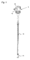
- FIG. 1 shows the complete push-button dispenser in its assembled state, ready to be screwed onto a bottle filled with carbonated beverage.
- the push-button dispenser consists of a head 1 and an infected on its underside suction tube 10, which is still provided at the lower mouth end with a mouthpiece 11. This has an increased density, so that the suction tube 10, when the bottle is due to the weight of the mouth piece 11 is curved downwards arc and the mouth piece 11 then comes to rest at the lowest point of the inside of the lying bottle, so always until last Liquid is sucked.
- FIG. 2 shows the head 1 with its parts in the assembled state, but in an enlarged view. It can be seen above the spout channel 15, which is closed here by a guarantee cover 2.
- This Jardiniedeckel 2 has a dome-shaped cover 29 on top, under which hides the actual push button of the dispenser.
- a cap 27 is formed, which closes the mouth of the spout 15.
- a warranty lug 28 which has at least one material bridge 33 with predetermined breaking point.
- this warranty cover 2 In the course of production of this warranty cover 2 is cheated on the underlying version 4 and after cooling of the parts of this warranty cover 2 can be removed only by breaking the breaking points on the material bridges 33 from the head 1 of the push button dispenser. It therefore provides a reliable first-hole guarantee and prevents any debris or foreign matter from entering the spout channel 15 before the purchaser removes this guarantee lid 2 for the first time.
- the version 4 forms on its one side the actual spout channel 15 with mouth 13, so a channel that leads from the inside to the outside. As you can see, this version 4 is shaped waisted on both sides. Thus, the version 4 can be easily grasped from above by grasping with two curved fingers, for instance between the index and middle fingers of one hand. A bottle equipped with this push-button dispenser can therefore be comfortably carried with two fingers.
- the Aufschraubmuffe 7 has for this purpose on its inside a corresponding thread, preferably a thread for the widespread 28mm nozzle of PET bottles. Other thread sizes are of course also possible.
- the upper end portion 12 of the subsequent conical flow channel 9 is inserted. At the lower end of this conical flow channel 9 sits a clamping socket 21 for the suction tube 10.
- This clamping socket 21 forms two gripper arms 31 which comprise the outer contour of the suction tube 10 accurately and inside the clamping socket 21 is formed so that the clear cross section of the suction tube 10th exactly merges into the inner contour of the terminal frame 21 and a smooth transition is ensured. This is important for laminar flow as possible and suppression of foaming in the carbonated beverage flowing through.
- FIG. 3 you can see the push button dispenser with all its components in an exploded view.
- a typical PET bottle 20 is shown as a size comparison, which is to be equipped with this push-button dispenser.
- the components of the push-button dispenser are described from top to bottom.
- the ISOiedeckel 2 with its dome-shaped cover 29 and its cap 27, which has formed on its inside a sealing ring 32, which thus sealingly comes to rest in the interior of the mouth 13 of the spout 15.
- Opposite is located on the guarantee cover 2, the guarantee lug 28, which is connected on both sides via fine material bridges 33 with predetermined breaking points with the comprehensive guarantee ring 34. Only when this warranty bag 28 is broken under breaking the material bridges 33, the guarantee cover 2 can be removed from the dispenser head 1 and the dispenser is ready for operation.
- the next component is the pushbutton 16 of the dispenser. On its underside two plastic springs 3 are formed, each in the form of three contiguous resilient elements. In the center, a coupling 14 is formed on the underside of the push button 16, in which the control element 5 is clickable, as will be shown.
- the next component is the socket 4 for the spout. It is shown here from behind and essentially comprises this spout 6, which can be seen below. The version 4 is designed waisted so that the dispenser can be easily grasped and carried with two fingers.
- the element shown below is the control element 5. It has the shape of an arrow with a countersunk-shaped sealing cone 23 at the front end, while it has a rear sword-shaped extension 24, with schiffchenförmigem cross-section.
- the coupling 14 on the underside of the push button 16 can be plugged together with the upper end of this extension 24, so that then the control element 5 can be depressed on the one hand by the push button 16, on the other hand force pulled down by the compression springs 3 is pulled back up again.
- This receiving sleeve 8 fits me on its outside in the upper end portion 12 of the conical flow channel 9, a plastic tube that widens conically from bottom to top in its interior.
- a clamping socket 21 for the suction tube 10 with two downwardly extending gripper arms 31, between which the suction tube 10 is inserted, so that a dense and smooth transition of its inner contour is achieved in those of the flow channel 9.
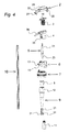
- FIG. 4 This push button dispenser with all its components is shown in another exploded view from a different angle. It can be seen again at the top of the ISiedeckel 2 with dome-shaped cover 29, and cap 27 and warranty flap 28. Below you can see the push button 16 with the two formed on its underside plastic compression springs 3. Then follows the waisted version 4 with the top cover 36 for the Ausgusskanal. It can be seen that the upper end of the socket 4 is at an angle to the mounting axis. This upper end forms an annular socket, in which the push button 16 fits, which is then also arranged obliquely to the mounting axis.
- This inclined plane is aligned with the spout channel, which is additionally arcuately slightly curved downwards, as can be seen from the cover 36 of the spout 15.
- an inwardly projecting projection 35 on which the lower ends of the compression springs 3 are supported after assembly.
- this push button dispenser is described in detail below on the basis of FIG. 5 described.
- a receiving sleeve 8 is inserted from above.
- the control element 5 is pushed from above through the upper end portion of the conical flow channel 9 and afterwards the receiving sleeve 8 is inserted from above. After that, the control element 5 can no longer be pulled upwards because it is enclosed by the receiving sleeve 8.
- the receiving sleeve 8 forms with its inner side for the shoulder of the countersunk sealing cone 23 of the control element 5, a sealing surface 25.
- the sealing cone 23 is down from the sealing surface 25 lifted away and it forms an annular gap.
- the pressure in the conical flow channel 9 is thereby reduced, and liquid flows from below around the sealing cone 23 due to the higher internal pressure in the bottle and flows around it upwards. The liquid finally passes through the spout channel 15 to the outside.
- the flow cross-section thus increases in the mass in which the differential pressure decreases. Through this trick, it is possible to achieve an approximately uniform mass flow when emptying the bottle.
- the outflow velocity is high, but the flow area is small. Gradually, the outflow velocity is reduced, but the flow area is increased.
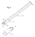
- the suction tube 10 is shown in a perspective view, with the associated Saugmündung Gla 11.
- the suction pipe 10 may have about such a cross-sectional shape, the outside is not circular and inside a flow channel 17 with both sides a subsequent extension 26 forms.
- the suction pipe 10 has a roundish cross-sectional shape on the outside, but the cross-section runs at an acute angle in each case on each side of a wing 18, and the inner hollow cross-section forms a central flow channel 17, with on both sides of the same subsequent flat projections 26 extending into the Wings 18 extend into it.
- Such a suction tube is preferably made of a rubber-elastic plastic, for example made of polyurethane silicone with a Shore C hardness of 40 to 60 and an inner diameter of the central channel of 1.5mm. This makes it possible to generate an approximately constant volume flow of approx. 1.3 to 1.4 l / min over the entire continuously reducing pressure difference range during dispensing. With harder material, for example with a Shore C hardness of 85 and more, the suction pipe behaves like a rigid pipe and the function is no longer guaranteed.
- FIG. 7 shows this preferred intake manifold cross-section left under the same pressure inside and outside, and right next to it with reduced pressure inside.
- the suction tube is therefore not completely circular outside and has inside a flow channel 17 with on both sides each a subsequent extension 26. It has a roundish cross-sectional shape, is about 9mm high and 13.5mm wide, and on both sides of the cross-section runs at an acute angle in each case a wing 18 with a rounded 55 ° tip, and the inner hollow cross section forms a central flow channel 17, with both sides the same subsequent flat, 1.3mm high projections 26, which each extend by 4.5mm laterally in the wings 18 inside.
- the suction pipe is compressed from the outside and with sufficient pressure difference the cross section is as shown in the figure on the right. Only the central channel 17 remains open, while the two Fort accounts 26 are left and right closed. Accordingly, the flow area is restricted.
- the extensions 26 open a gap wide and then with decreasing pressure difference more and more, so they gradually release the entire flow cross-section as shown in the picture on the left.
- the effective flow rate remains similar across the entire pressure drop. Ideally, it is about 1.3 to 1.4 l / min.
- FIG. 8 is an alternative intake manifold cross-section under the same pressure inside and outside and shown right next to it with reduced pressure inside.
- the suction tube simply has a rectangular cross-section with on the inside a flattened flow channel with semicircular side walls. Under high external pressure and low internal pressure, the suction tube is completely compressed in the central area as shown in the picture on the right, so that the flow channel is closed in this area, and two flow passages are formed with an overall greatly reduced flow cross section. When the external pressure decreases, the suction tube gradually opens up to the relaxed position in the picture on the left.
- FIG. 9 is a suction tube with star-shaped cross-section under the same pressure inside and outside and shown right next to it with reduced pressure inside.
- the higher external pressure acts in a squeezing of the star-shaped protruding wings, so that at maximum external pressure, only an approximately diamond-shaped central cross-section remains free as a flow channel.
- FIG. 10 shows a dumbbell-shaped intake manifold cross-section under the same pressure inside and outside and to the right with reduced pressure in the interior.
- the higher external pressure in a complete squeezing of the central region of this suction tube affects, with a circular small flow channel remains open on both sides.
- the middle area gradually opens up to the relaxed position shown on the left side of the picture.
- a flow rate can be generated which remains approximately constant over an entire range of a pressure difference of for example 10 5 Pa to 5 x 10 5 Pa, namely approximately between 1.3 and 1.4 l / min. This behavior is under in the diagram FIG. 11 shown.
- the suction tube 10 made of rubber-elastic plastic, however, still has a certain rigidity, so that it would bend in a lying bottle only slightly from the central axis of the bottle down. So that in a horizontal bottle, the entire contents can be removed due to the prevailing internal pressure, the suction pipe 10 is equipped at its lower end with a mouthpiece 11. This has a density between 2.8 and 3.2 g / ml and is attached to the suction tube 10 from below, so that the suction mouth of the suction tube 10 comes to lie at the lowest point of the bottle interior by virtue of the weight of this mouthpiece 11 when the bottle is lying.
- the mouth piece 11 is made of, for example, a thermoplastic polybutylene terephthalate PBT and enriched with rock meal and mixed in order to achieve this high density and, correspondingly, a high weight.
- this push-button dispenser offers even more advantages. Due to the special design of the Ausgiesskanals from the mouth piece 11, namely by the conical extension following the suction pipe 10, a deceleration of the outflow is achieved, which significantly suppresses the formation of foam. After flowing around the sealing cone 23, the liquid initially follows a piece along the sword-shaped extension of the control element 5. Only then it enters the actual spout channel 15 then flows out of the pressure out of this. Experiments showed that a bottle with this push-button dispenser can be emptied practically to a few residual drops, with little foaming.
- this push-button dispenser consists of an exceptionally low number of components, it is reasonably inexpensive to manufacture and easy to assemble, making it an ideal mass-produced product. Due to the fact that it is made entirely of plastic parts, it is also a disposable dispenser whose parts can all be recycled or incinerated. It even offers a first-opening guarantee and allows a bottle equipped with it to be conveniently carried around hanging between two curved fingers.
Claims (12)
- Distributeur à bouton-poussoir pour des bouteilles comprenant des boissons gazéifiées avec une tête (1) pouvant être vissée sur une bouteille, avec un bec verseur latéral (15), le bouton-poussoir (16) sur son côté supérieur et un tube d'aspiration (10) saillant vers le bas, qui est prévu pour s'étendre vers le bas jusqu'au fond de la bouteille (20) à équiper, et qui débouche en haut dans la tête (1) dans un dispositif de soupape qui présente un organe de réglage (5) déplaçable axialement par rapport à la bouteille (20), qui est sollicité dans la direction de fermeture par un ressort (3) et qui peut être sollicité en vue de l'ouverture par le haut par une pression de la main sur le bouton-poussoir (16) de telle sorte que la pression à l'intérieur du tube d'aspiration (10) puisse être réduite à la pression atmosphérique, de sorte que du liquide puisse être évacué de la bouteille (20) par la pression intérieure régnant dans la bouteille (20) par l'embouchure inférieure du tube d'aspiration (10) par le biais du bec verseur (15), caractérisé en ce que
le tube d'aspiration (10) est fabriqué en un plastique ayant l'élasticité du caoutchouc et sa section transversale extérieure et sa section transversale intérieure sont configurées de telle sorte que sa section transversale d'écoulement puisse être rétrécie par déformation lorsque la pression intérieure est réduite à la pression atmosphérique par rapport à la pression accrue régnant à l'extérieur ; et caractérisé en outre en ce que le tube d'aspiration (10) est inséré avec son extrémité supérieure de manière hermétique dans un raccord de serrage (21) dans lequel son canal d'écoulement est reçu avec ajustement serré et se prolonge ensuite par un canal d'écoulement s'élargissant coniquement (9) ayant une forme intérieure en section transversale (22) approximativement identique ou identique, ce canal d'écoulement (9) formant en haut une région d'extrémité (12) dans laquelle est insérée une douille de réception (8) moulée par injection par une technique à deux composants avec une surface d'étanchéité surmoulée à l'intérieure (25), à travers laquelle s'étend l'organe de réglage (5) qui se compose d'un cône d'étanchéité (23) en forme de fil à plomb avec une saillie (24) en forme d'épée vers le haut, le cône d'étanchéité (23) s'appliquant par le bas avec son épaulement contre la surface d'étanchéité (25) en ce que sa saillie (24) en forme d'épée est tirée vers le haut au niveau de son extrémité supérieure par le bouton-poussoir (16) sous l'effet de la force des ressorts de compression (3), et lorsque l'organe de réglage (5) est sollicité par une pression de la main par le haut, le cône d'étanchéité (23) pouvant être soulevé à l'encontre de la force des ressorts de compression (3) vers le bas à l'écart de la surface d'étanchéité (25) de sorte que le liquide entraîné depuis le tube d'aspiration (10) circule de tous les côtés autour du cône d'étanchéité (23) et s'écoule ensuite le long de la saillie (24) en forme d'épée puis sorte vers l'extérieur par le biais du canal de bec verseur (15). - Distributeur à bouton-poussoir pour des bouteilles comprenant des boissons gazéifiées selon la revendication 1, caractérisé en ce que le tube d'aspiration (10) présente une forme en section transversale qui n'est pas circulaire à l'extérieur et qui forme à l'intérieur un canal d'écoulement (17) ayant une saillie plate (26) respective se raccordant de chaque côté.
- Distributeur à bouton-poussoir pour des bouteilles comprenant des boissons gazéifiées selon la revendication 1, caractérisé en ce que le tube d'aspiration (10) présente à l'extérieur une forme en section transversale arrondie d'un rayon de 4,5 mm, mais en outre se termine à l'extérieur au niveau de deux côtés opposés à chaque fois par une aile saillante (18) se terminant à angle aigu en section transversale, de sorte que sa largeur soit dans l'ensemble de 13,5 mm, et en ce que la section transversale intérieure creuse forme un canal d'écoulement central (17) avec des saillies plates (26) s'y raccordant de chaque côté, lesquelles s'étendent à l'intérieur des ailes (18), le canal d'écoulement central (17), dans l'état comprimé des saillies (26), ayant un diamètre intérieur de 1,5 mm.
- Distributeur à bouton-poussoir pour des bouteilles comprenant des boissons gazéifiées selon la revendication 1, caractérisé en ce que le tube d'aspiration (10) présente à l'extérieur une forme en section transversale rectangulaire et forme à l'intérieur un canal d'écoulement aplati (17) avec des parois latérales en forme de demi-cercle de sorte que lorsque la pression intérieure est réduite à la pression atmosphérique par rapport à la pression accrue régnant à l'extérieur, sa section transversale d'écoulement puisse être rétrécie par déformation, en ce que le canal d'écoulement (17) peut être complètement écrasé au centre de telle sorte qu'il subsiste seulement au niveau de ses deux côtés un canal d'écoulement respectif.
- Distributeur à bouton-poussoir pour des bouteilles comprenant des boissons gazéifiées selon la revendication 1, caractérisé en ce que le tube d'aspiration (10) présente à l'extérieur une forme en section transversale elliptique et forme à l'intérieur un canal d'écoulement aplati sur la direction longitudinale de la forme en section transversale elliptique.
- Distributeur à bouton-poussoir pour des bouteilles comprenant des boissons gazéifiées selon la revendication 1, caractérisé en ce que le tube d'aspiration (10) présente, en section transversale, une forme d'haltère avec un canal d'écoulement s'étendant à l'intérieur sur approximativement toute la largeur, de sorte qu'il soit complètement écrasé lorsqu'une pression extérieure accrue par rapport à la pression intérieure règne dans la région centrale et qu'il ne reste ouvert qu'au niveau des deux régions de bord du canal d'écoulement.
- Distributeur à bouton-poussoir pour des bouteilles comprenant des boissons gazéifiées selon l'une quelconque des revendications 1 à 6, caractérisé en ce que le tube d'aspiration (10) est fabriqué en silicone de polyuréthane avec une dureté Shore C de 40 à 60.
- Distributeur à bouton-poussoir pour des bouteilles comprenant des boissons gazéifiées selon l'une quelconque des revendications précédentes, caractérisé en ce que la tête (1) pouvant être vissée sur une bouteille se compose d'un raccord (4) pour le recouvrement sur la partie de bec verseur (6) avec un guide pour l'organe de réglage (5), et en ce que le ressort de compression (3) est un ressort en plastique moulé par injection à partir de plusieurs éléments élastiques en traction, qui peut être accouplé par engagement par force avec le côté inférieur du bouton-poussoir (16), lequel repose en haut dans le raccord (4).
- Distributeur à bouton-poussoir pour des bouteilles comprenant des boissons gazéifiées selon l'une quelconque des revendications précédentes, caractérisé en ce que la tête (1) présente un raccord (4) qui a une forme cintrée latéralement de telle sorte qu'il puisse être saisi par le haut entre l'index et le majeur de la main et qu'une bouteille (20) équipée du distributeur à bouton-poussoir puisse ainsi être portée par deux doigts.
- Distributeur à bouton-poussoir pour des bouteilles comprenant des boissons gazéifiées selon l'une quelconque des revendications précédentes, caractérisé en ce que la tête (1) présente un raccord (4) pour recevoir le bouton-poussoir (16), et le raccord (4) forme en haut une bague située en biais par rapport à la direction de déplacement de l'organe de réglage (5), laquelle entoure le bouton-poussoir introduit (16), et laquelle bague, à partir de son point le plus bas, se termine par un recouvrement (36) de forme arquée courbé vers le bas pour le canal de bec verseur (15), et en ce qu'un couvercle de garantie associé (2) peut en outre être encliqueté par le haut sur le raccord (4) et son recouvrement courbe (30), ce couvercle de garantie (2) formant un capuchon de recouvrement (27) pour l'embouchure (13) du canal de bec verseur (15) et, sur son côté opposé, le couvercle de garantie (2) présentant une patte de garantie (28) faisant saillie vers le bas au-dessus de ponts de matériau (33) avec des points destinés à la rupture, laquelle, lors du montage du couvercle de garantie (2), peut être encliquetée sur le raccord (4) et ne peut être enlevée que par rupture de ses points destinés à la rupture avec le couvercle de garantie (2).
- Distributeur à bouton-poussoir pour des bouteilles comprenant des boissons gazéifiées selon l'une quelconque des revendications précédentes, caractérisé en ce qu'une pièce d'embouchure (11) ayant une densité comprise entre 2,8 et 3,2 g/ml est enfichée sur l'embouchure inférieure du tube d'aspiration (10), de sorte que lorsque la bouteille équipée du distributeur à bouton-poussoir est couchée, l'embouchure d'aspiration du tube d'aspiration (10), sous l'effet du poids de la pièce d'embouchure (11), vienne se placer au point le plus bas de l'intérieur de la bouteille.
- Distributeur à bouton-poussoir pour des bouteilles comprenant des boissons gazéifiées selon la revendication 11, caractérisé en ce que cette pièce d'embouchure (11) se compose d'un polybutylènetéréphtalate thermoplastique PBT additionné de farine de roche.
Applications Claiming Priority (2)
| Application Number | Priority Date | Filing Date | Title |
|---|---|---|---|
| CH00625/10A CH703028B1 (de) | 2010-04-28 | 2010-04-28 | Druckknopf-Dispenser für Flaschen mit karbonisierten Getränken. |
| PCT/EP2011/056522 WO2011134928A2 (fr) | 2010-04-28 | 2011-04-26 | Distributeur à bouton-poussoir pour bouteilles contenant des boissons gazéifiées |
Publications (2)
| Publication Number | Publication Date |
|---|---|
| EP2563711A2 EP2563711A2 (fr) | 2013-03-06 |
| EP2563711B1 true EP2563711B1 (fr) | 2015-11-04 |
Family
ID=44225233
Family Applications (1)
| Application Number | Title | Priority Date | Filing Date |
|---|---|---|---|
| EP11717559.6A Not-in-force EP2563711B1 (fr) | 2010-04-28 | 2011-04-26 | Distributeur à bouton-poussoir pour bouteilles contenant des boissons gazéifiées |
Country Status (10)
| Country | Link |
|---|---|
| US (1) | US8870038B2 (fr) |
| EP (1) | EP2563711B1 (fr) |
| JP (1) | JP5722432B2 (fr) |
| CN (1) | CN102906005B (fr) |
| AU (1) | AU2011246511B2 (fr) |
| CH (1) | CH703028B1 (fr) |
| MX (1) | MX2012012499A (fr) |
| RU (1) | RU2012148844A (fr) |
| WO (1) | WO2011134928A2 (fr) |
| ZA (1) | ZA201208108B (fr) |
Families Citing this family (12)
| Publication number | Priority date | Publication date | Assignee | Title |
|---|---|---|---|---|
| US20140113045A1 (en) * | 2012-10-18 | 2014-04-24 | Starbucks Corporation D/B/A Starbucks Coffee Company | Apparatus for carbonating beverages |
| US9114368B2 (en) | 2013-03-08 | 2015-08-25 | Cornelius, Inc. | Batch carbonator and method of forming a carbonated beverage |
| BE1022701B1 (nl) * | 2015-02-04 | 2016-08-16 | SenS-Projects BVBA | Drukcontainer |
| KR101723155B1 (ko) * | 2015-02-16 | 2017-04-05 | 주식회사 태성트레이딩 | 탄산음료 제조장치의 음료 배출장치 |
| US10785996B2 (en) | 2015-08-25 | 2020-09-29 | Cornelius, Inc. | Apparatuses, systems, and methods for inline injection of gases into liquids |
| US10477883B2 (en) | 2015-08-25 | 2019-11-19 | Cornelius, Inc. | Gas injection assemblies for batch beverages having spargers |
| CN106862207A (zh) * | 2016-12-23 | 2017-06-20 | 贵州大学 | 一种实验室用手压式洗瓶装置 |
| FR3065176B1 (fr) * | 2017-04-13 | 2019-06-07 | Aptar France Sas | Valve doseuse pour distributeur de produit fluide |
| US11040314B2 (en) | 2019-01-08 | 2021-06-22 | Marmon Foodservice Technologies, Inc. | Apparatuses, systems, and methods for injecting gasses into beverages |
| JP7220580B2 (ja) * | 2019-02-08 | 2023-02-10 | 東京エレクトロン株式会社 | チューブ体及びポンプ装置 |
| EA038731B1 (ru) * | 2019-07-09 | 2021-10-12 | Станислав Сергеевич Гончаров | Пробка-дозатор сосуда для хранения и раздачи газированного напитка |
| AR117845A1 (es) * | 2020-01-20 | 2021-09-01 | Sidel Sa | Conjunto de tapón valvular para cabezales de sifón |
Family Cites Families (18)
| Publication number | Priority date | Publication date | Assignee | Title |
|---|---|---|---|---|
| US3976221A (en) | 1974-06-28 | 1976-08-24 | Gmf Inc. | Carbonator and dispenser for carbonated liquid or the like |
| FR2370213A1 (fr) * | 1976-11-04 | 1978-06-02 | Oreal | Valve doseuse pour recipient pressurise du type " bombe aerosol " et recipient correspondant |
| US4286636A (en) * | 1979-07-19 | 1981-09-01 | The Coca-Cola Company | Dip tube and valve with quick-disconnect coupling for a collapsible container |
| JPS629279Y2 (fr) * | 1981-06-05 | 1987-03-04 | ||
| GB8321568D0 (en) | 1983-08-10 | 1983-09-14 | Ici Plc | Apparatus for dispensing liquids |
| US4671436A (en) * | 1984-07-31 | 1987-06-09 | Mckesson Corporation | Syphon assembly and package incorporating the assembly |
| GB2219988A (en) | 1988-06-22 | 1989-12-28 | Kineret Engineering | Carbonated soft drink dispenser |
| US4995534A (en) * | 1989-09-07 | 1991-02-26 | Texpro, Inc. | Detachable volved dispensing head for bottle |
| FR2687643B1 (fr) | 1992-02-24 | 1995-04-28 | Oreal | Recipient distributeur de fluide. |
| BE1006130A3 (nl) * | 1992-08-19 | 1994-05-17 | Belgium Spray Accessory Factor | Spuitbus. |
| US5518151A (en) * | 1994-04-25 | 1996-05-21 | Aptar Group, Inc. | Dip tube for hand operated dispensing device |
| JP3865920B2 (ja) * | 1998-02-13 | 2007-01-10 | 株式会社コガネイ | 薬液供給装置 |
| US6253965B1 (en) * | 2000-02-28 | 2001-07-03 | Sides S.A. | Valve heads for soft drink bottles and the like |
| US7641080B2 (en) * | 2004-03-17 | 2010-01-05 | Pepsico., Inc. | Dispensing mechanism using long tubes to vary pressure drop |
| DE102004017171A1 (de) | 2004-04-02 | 2005-10-20 | Huber Verpackungen Gmbh & Co K | Vorrichtung zur Ausgabe eines Fluides aus einem Hohlraum eines Behälters |
| JP4204573B2 (ja) * | 2004-08-30 | 2009-01-07 | 株式会社三ツ星 | ローラーポンプ用チューブ |
| JP4942449B2 (ja) * | 2006-10-18 | 2012-05-30 | 株式会社コガネイ | 薬液供給装置 |
| US8191740B2 (en) * | 2008-05-19 | 2012-06-05 | Millercoors, Llc | Modular constructed regulated fluid dispensing device |
-
2010
- 2010-04-28 CH CH00625/10A patent/CH703028B1/de not_active IP Right Cessation
-
2011
- 2011-04-26 EP EP11717559.6A patent/EP2563711B1/fr not_active Not-in-force
- 2011-04-26 RU RU2012148844/12A patent/RU2012148844A/ru not_active Application Discontinuation
- 2011-04-26 AU AU2011246511A patent/AU2011246511B2/en not_active Expired - Fee Related
- 2011-04-26 CN CN201180025174.8A patent/CN102906005B/zh not_active Expired - Fee Related
- 2011-04-26 WO PCT/EP2011/056522 patent/WO2011134928A2/fr active Application Filing
- 2011-04-26 MX MX2012012499A patent/MX2012012499A/es active IP Right Grant
- 2011-04-26 JP JP2013506616A patent/JP5722432B2/ja not_active Expired - Fee Related
- 2011-04-26 US US13/643,454 patent/US8870038B2/en active Active
-
2012
- 2012-10-26 ZA ZA2012/08108A patent/ZA201208108B/en unknown
Also Published As
| Publication number | Publication date |
|---|---|
| MX2012012499A (es) | 2012-12-17 |
| US20130092712A1 (en) | 2013-04-18 |
| ZA201208108B (en) | 2013-07-31 |
| WO2011134928A2 (fr) | 2011-11-03 |
| RU2012148844A (ru) | 2014-06-10 |
| WO2011134928A3 (fr) | 2012-01-05 |
| JP5722432B2 (ja) | 2015-05-20 |
| CH703028A2 (de) | 2011-10-31 |
| US8870038B2 (en) | 2014-10-28 |
| AU2011246511B2 (en) | 2015-08-20 |
| CH703028B1 (de) | 2014-05-30 |
| AU2011246511A1 (en) | 2012-12-20 |
| CN102906005A (zh) | 2013-01-30 |
| CN102906005B (zh) | 2015-09-16 |
| EP2563711A2 (fr) | 2013-03-06 |
| JP2013529158A (ja) | 2013-07-18 |
Similar Documents
| Publication | Publication Date | Title |
|---|---|---|
| EP2563711B1 (fr) | Distributeur à bouton-poussoir pour bouteilles contenant des boissons gazéifiées | |
| DE60126605T2 (de) | Behälter für kohlensäurehaltige getränke mit ausgiesstülle | |
| DE69916034T2 (de) | Entnahmeverschluss für einen getränkebehälter | |
| EP2723650B1 (fr) | Dispositif de fermeture remplissable permettant de declancher le vidage d'une capsule | |
| EP1642861B1 (fr) | Récipient avec une source de CO2 sous pression | |
| WO2011134929A2 (fr) | Distributeur à bouton-poussoir et à capsule de gaz comprimé pour bouteilles de boisson | |
| EP2457842B1 (fr) | Fermeture pour bouteille de boisson refermable automatiquement | |
| DE112010005489T5 (de) | Verschluss für einen auf dem Kopf stehenden Behälter | |
| WO2012129712A1 (fr) | Fermeture de récipient | |
| DE202007015543U1 (de) | Behälter mit Deckel | |
| WO2009023976A1 (fr) | Système de bouchage à ouverture automatique muni d'un canal d'entrée d'air pour emballages composites ou pour embouts de récipients à obturer par un matériau pelliculaire | |
| CH695776A5 (de) | Brausetablettenspender. | |
| WO2006128653A1 (fr) | Cylindre a source de gaz co2 sous pression | |
| DE102007050000A1 (de) | Trinkhalm | |
| WO2004000672A1 (fr) | Bouchon de contenant autoetancheifiant | |
| EP3625523B1 (fr) | Dispositif de dosage pour l'alimentation liquide avec un élément tubulaire | |
| AT506166B1 (de) | Verschluss | |
| DE202006016173U1 (de) | Trinkhalm | |
| DE102014014305B3 (de) | Ausgießer | |
| DE202005009312U1 (de) | Flaschenförmiges Gefäß und Vorrichtung zum Begasen einer Flüssigkeit | |
| EP1809549B1 (fr) | Robinets pour recipients a boisson | |
| AT521608B1 (de) | Flaschenhalter | |
| DE19705282C2 (de) | Auslaufgeschützter Trinkgefäß-Aufsatz | |
| DE202008001732U1 (de) | Flexibler Ausguß am Behältnis | |
| AT234025B (de) | Verschluß für Flüssigkeits- oder Gasbehälter |
Legal Events
| Date | Code | Title | Description |
|---|---|---|---|
| PUAI | Public reference made under article 153(3) epc to a published international application that has entered the european phase |
Free format text: ORIGINAL CODE: 0009012 |
|
| 17P | Request for examination filed |
Effective date: 20121123 |
|
| AK | Designated contracting states |
Kind code of ref document: A2 Designated state(s): AL AT BE BG CH CY CZ DE DK EE ES FI FR GB GR HR HU IE IS IT LI LT LU LV MC MK MT NL NO PL PT RO RS SE SI SK SM TR |
|
| DAX | Request for extension of the european patent (deleted) | ||
| GRAP | Despatch of communication of intention to grant a patent |
Free format text: ORIGINAL CODE: EPIDOSNIGR1 |
|
| INTG | Intention to grant announced |
Effective date: 20150520 |
|
| GRAS | Grant fee paid |
Free format text: ORIGINAL CODE: EPIDOSNIGR3 |
|
| GRAA | (expected) grant |
Free format text: ORIGINAL CODE: 0009210 |
|
| AK | Designated contracting states |
Kind code of ref document: B1 Designated state(s): AL AT BE BG CH CY CZ DE DK EE ES FI FR GB GR HR HU IE IS IT LI LT LU LV MC MK MT NL NO PL PT RO RS SE SI SK SM TR |
|
| REG | Reference to a national code |
Ref country code: GB Ref legal event code: FG4D Free format text: NOT ENGLISH |
|
| REG | Reference to a national code |
Ref country code: CH Ref legal event code: EP |
|
| REG | Reference to a national code |
Ref country code: AT Ref legal event code: REF Ref document number: 759034 Country of ref document: AT Kind code of ref document: T Effective date: 20151115 |
|
| REG | Reference to a national code |
Ref country code: IE Ref legal event code: FG4D Free format text: LANGUAGE OF EP DOCUMENT: GERMAN |
|
| REG | Reference to a national code |
Ref country code: DE Ref legal event code: R096 Ref document number: 502011008276 Country of ref document: DE |
|
| REG | Reference to a national code |
Ref country code: NL Ref legal event code: MP Effective date: 20151104 |
|
| REG | Reference to a national code |
Ref country code: LT Ref legal event code: MG4D |
|
| PG25 | Lapsed in a contracting state [announced via postgrant information from national office to epo] |
Ref country code: NL Free format text: LAPSE BECAUSE OF FAILURE TO SUBMIT A TRANSLATION OF THE DESCRIPTION OR TO PAY THE FEE WITHIN THE PRESCRIBED TIME-LIMIT Effective date: 20151104 Ref country code: LT Free format text: LAPSE BECAUSE OF FAILURE TO SUBMIT A TRANSLATION OF THE DESCRIPTION OR TO PAY THE FEE WITHIN THE PRESCRIBED TIME-LIMIT Effective date: 20151104 Ref country code: ES Free format text: LAPSE BECAUSE OF FAILURE TO SUBMIT A TRANSLATION OF THE DESCRIPTION OR TO PAY THE FEE WITHIN THE PRESCRIBED TIME-LIMIT Effective date: 20151104 Ref country code: IT Free format text: LAPSE BECAUSE OF FAILURE TO SUBMIT A TRANSLATION OF THE DESCRIPTION OR TO PAY THE FEE WITHIN THE PRESCRIBED TIME-LIMIT Effective date: 20151104 Ref country code: HR Free format text: LAPSE BECAUSE OF FAILURE TO SUBMIT A TRANSLATION OF THE DESCRIPTION OR TO PAY THE FEE WITHIN THE PRESCRIBED TIME-LIMIT Effective date: 20151104 Ref country code: IS Free format text: LAPSE BECAUSE OF FAILURE TO SUBMIT A TRANSLATION OF THE DESCRIPTION OR TO PAY THE FEE WITHIN THE PRESCRIBED TIME-LIMIT Effective date: 20160304 Ref country code: NO Free format text: LAPSE BECAUSE OF FAILURE TO SUBMIT A TRANSLATION OF THE DESCRIPTION OR TO PAY THE FEE WITHIN THE PRESCRIBED TIME-LIMIT Effective date: 20160204 |
|
| PG25 | Lapsed in a contracting state [announced via postgrant information from national office to epo] |
Ref country code: PT Free format text: LAPSE BECAUSE OF FAILURE TO SUBMIT A TRANSLATION OF THE DESCRIPTION OR TO PAY THE FEE WITHIN THE PRESCRIBED TIME-LIMIT Effective date: 20160304 Ref country code: GR Free format text: LAPSE BECAUSE OF FAILURE TO SUBMIT A TRANSLATION OF THE DESCRIPTION OR TO PAY THE FEE WITHIN THE PRESCRIBED TIME-LIMIT Effective date: 20160205 Ref country code: RS Free format text: LAPSE BECAUSE OF FAILURE TO SUBMIT A TRANSLATION OF THE DESCRIPTION OR TO PAY THE FEE WITHIN THE PRESCRIBED TIME-LIMIT Effective date: 20151104 Ref country code: SE Free format text: LAPSE BECAUSE OF FAILURE TO SUBMIT A TRANSLATION OF THE DESCRIPTION OR TO PAY THE FEE WITHIN THE PRESCRIBED TIME-LIMIT Effective date: 20151104 Ref country code: FI Free format text: LAPSE BECAUSE OF FAILURE TO SUBMIT A TRANSLATION OF THE DESCRIPTION OR TO PAY THE FEE WITHIN THE PRESCRIBED TIME-LIMIT Effective date: 20151104 Ref country code: PL Free format text: LAPSE BECAUSE OF FAILURE TO SUBMIT A TRANSLATION OF THE DESCRIPTION OR TO PAY THE FEE WITHIN THE PRESCRIBED TIME-LIMIT Effective date: 20151104 Ref country code: LV Free format text: LAPSE BECAUSE OF FAILURE TO SUBMIT A TRANSLATION OF THE DESCRIPTION OR TO PAY THE FEE WITHIN THE PRESCRIBED TIME-LIMIT Effective date: 20151104 |
|
| PG25 | Lapsed in a contracting state [announced via postgrant information from national office to epo] |
Ref country code: CZ Free format text: LAPSE BECAUSE OF FAILURE TO SUBMIT A TRANSLATION OF THE DESCRIPTION OR TO PAY THE FEE WITHIN THE PRESCRIBED TIME-LIMIT Effective date: 20151104 |
|
| REG | Reference to a national code |
Ref country code: DE Ref legal event code: R097 Ref document number: 502011008276 Country of ref document: DE |
|
| PG25 | Lapsed in a contracting state [announced via postgrant information from national office to epo] |
Ref country code: RO Free format text: LAPSE BECAUSE OF FAILURE TO SUBMIT A TRANSLATION OF THE DESCRIPTION OR TO PAY THE FEE WITHIN THE PRESCRIBED TIME-LIMIT Effective date: 20151104 Ref country code: EE Free format text: LAPSE BECAUSE OF FAILURE TO SUBMIT A TRANSLATION OF THE DESCRIPTION OR TO PAY THE FEE WITHIN THE PRESCRIBED TIME-LIMIT Effective date: 20151104 Ref country code: SK Free format text: LAPSE BECAUSE OF FAILURE TO SUBMIT A TRANSLATION OF THE DESCRIPTION OR TO PAY THE FEE WITHIN THE PRESCRIBED TIME-LIMIT Effective date: 20151104 Ref country code: SM Free format text: LAPSE BECAUSE OF FAILURE TO SUBMIT A TRANSLATION OF THE DESCRIPTION OR TO PAY THE FEE WITHIN THE PRESCRIBED TIME-LIMIT Effective date: 20151104 Ref country code: DK Free format text: LAPSE BECAUSE OF FAILURE TO SUBMIT A TRANSLATION OF THE DESCRIPTION OR TO PAY THE FEE WITHIN THE PRESCRIBED TIME-LIMIT Effective date: 20151104 Ref country code: BE Free format text: LAPSE BECAUSE OF NON-PAYMENT OF DUE FEES Effective date: 20160430 |
|
| PLBE | No opposition filed within time limit |
Free format text: ORIGINAL CODE: 0009261 |
|
| STAA | Information on the status of an ep patent application or granted ep patent |
Free format text: STATUS: NO OPPOSITION FILED WITHIN TIME LIMIT |
|
| 26N | No opposition filed |
Effective date: 20160805 |
|
| REG | Reference to a national code |
Ref country code: DE Ref legal event code: R119 Ref document number: 502011008276 Country of ref document: DE |
|
| PG25 | Lapsed in a contracting state [announced via postgrant information from national office to epo] |
Ref country code: SI Free format text: LAPSE BECAUSE OF FAILURE TO SUBMIT A TRANSLATION OF THE DESCRIPTION OR TO PAY THE FEE WITHIN THE PRESCRIBED TIME-LIMIT Effective date: 20151104 |
|
| REG | Reference to a national code |
Ref country code: CH Ref legal event code: PL |
|
| GBPC | Gb: european patent ceased through non-payment of renewal fee |
Effective date: 20160426 |
|
| PG25 | Lapsed in a contracting state [announced via postgrant information from national office to epo] |
Ref country code: LU Free format text: LAPSE BECAUSE OF FAILURE TO SUBMIT A TRANSLATION OF THE DESCRIPTION OR TO PAY THE FEE WITHIN THE PRESCRIBED TIME-LIMIT Effective date: 20160426 |
|
| REG | Reference to a national code |
Ref country code: IE Ref legal event code: MM4A |
|
| REG | Reference to a national code |
Ref country code: FR Ref legal event code: ST Effective date: 20161230 |
|
| PG25 | Lapsed in a contracting state [announced via postgrant information from national office to epo] |
Ref country code: DE Free format text: LAPSE BECAUSE OF NON-PAYMENT OF DUE FEES Effective date: 20161101 Ref country code: CH Free format text: LAPSE BECAUSE OF NON-PAYMENT OF DUE FEES Effective date: 20160430 Ref country code: GB Free format text: LAPSE BECAUSE OF NON-PAYMENT OF DUE FEES Effective date: 20160426 Ref country code: LI Free format text: LAPSE BECAUSE OF NON-PAYMENT OF DUE FEES Effective date: 20160430 Ref country code: FR Free format text: LAPSE BECAUSE OF NON-PAYMENT OF DUE FEES Effective date: 20160502 |
|
| PG25 | Lapsed in a contracting state [announced via postgrant information from national office to epo] |
Ref country code: IE Free format text: LAPSE BECAUSE OF NON-PAYMENT OF DUE FEES Effective date: 20160426 |
|
| REG | Reference to a national code |
Ref country code: AT Ref legal event code: MM01 Ref document number: 759034 Country of ref document: AT Kind code of ref document: T Effective date: 20160426 |
|
| PG25 | Lapsed in a contracting state [announced via postgrant information from national office to epo] |
Ref country code: AT Free format text: LAPSE BECAUSE OF NON-PAYMENT OF DUE FEES Effective date: 20160426 |
|
| PG25 | Lapsed in a contracting state [announced via postgrant information from national office to epo] |
Ref country code: HU Free format text: LAPSE BECAUSE OF FAILURE TO SUBMIT A TRANSLATION OF THE DESCRIPTION OR TO PAY THE FEE WITHIN THE PRESCRIBED TIME-LIMIT; INVALID AB INITIO Effective date: 20110426 Ref country code: CY Free format text: LAPSE BECAUSE OF FAILURE TO SUBMIT A TRANSLATION OF THE DESCRIPTION OR TO PAY THE FEE WITHIN THE PRESCRIBED TIME-LIMIT Effective date: 20151104 |
|
| PG25 | Lapsed in a contracting state [announced via postgrant information from national office to epo] |
Ref country code: MK Free format text: LAPSE BECAUSE OF FAILURE TO SUBMIT A TRANSLATION OF THE DESCRIPTION OR TO PAY THE FEE WITHIN THE PRESCRIBED TIME-LIMIT Effective date: 20151104 Ref country code: TR Free format text: LAPSE BECAUSE OF FAILURE TO SUBMIT A TRANSLATION OF THE DESCRIPTION OR TO PAY THE FEE WITHIN THE PRESCRIBED TIME-LIMIT Effective date: 20151104 Ref country code: MC Free format text: LAPSE BECAUSE OF FAILURE TO SUBMIT A TRANSLATION OF THE DESCRIPTION OR TO PAY THE FEE WITHIN THE PRESCRIBED TIME-LIMIT Effective date: 20151104 Ref country code: MT Free format text: LAPSE BECAUSE OF FAILURE TO SUBMIT A TRANSLATION OF THE DESCRIPTION OR TO PAY THE FEE WITHIN THE PRESCRIBED TIME-LIMIT Effective date: 20151104 |
|
| PG25 | Lapsed in a contracting state [announced via postgrant information from national office to epo] |
Ref country code: BG Free format text: LAPSE BECAUSE OF FAILURE TO SUBMIT A TRANSLATION OF THE DESCRIPTION OR TO PAY THE FEE WITHIN THE PRESCRIBED TIME-LIMIT Effective date: 20151104 |
|
| PG25 | Lapsed in a contracting state [announced via postgrant information from national office to epo] |
Ref country code: AL Free format text: LAPSE BECAUSE OF FAILURE TO SUBMIT A TRANSLATION OF THE DESCRIPTION OR TO PAY THE FEE WITHIN THE PRESCRIBED TIME-LIMIT Effective date: 20151104 |