EP2561295B2 - Four à flamme et procédé de régulation de la combustion dans un four à flamme - Google Patents
Four à flamme et procédé de régulation de la combustion dans un four à flamme Download PDFInfo
- Publication number
- EP2561295B2 EP2561295B2 EP11719312.8A EP11719312A EP2561295B2 EP 2561295 B2 EP2561295 B2 EP 2561295B2 EP 11719312 A EP11719312 A EP 11719312A EP 2561295 B2 EP2561295 B2 EP 2561295B2
- Authority
- EP
- European Patent Office
- Prior art keywords
- combustion chamber
- rate
- flame
- injection
- flame intensity
- Prior art date
- Legal status (The legal status is an assumption and is not a legal conclusion. Google has not performed a legal analysis and makes no representation as to the accuracy of the status listed.)
- Active
Links
Images
Classifications
-
- F—MECHANICAL ENGINEERING; LIGHTING; HEATING; WEAPONS; BLASTING
- F23—COMBUSTION APPARATUS; COMBUSTION PROCESSES
- F23G—CREMATION FURNACES; CONSUMING WASTE PRODUCTS BY COMBUSTION
- F23G7/00—Incinerators or other apparatus for consuming industrial waste, e.g. chemicals
- F23G7/06—Incinerators or other apparatus for consuming industrial waste, e.g. chemicals of waste gases or noxious gases, e.g. exhaust gases
- F23G7/061—Incinerators or other apparatus for consuming industrial waste, e.g. chemicals of waste gases or noxious gases, e.g. exhaust gases with supplementary heating
- F23G7/065—Incinerators or other apparatus for consuming industrial waste, e.g. chemicals of waste gases or noxious gases, e.g. exhaust gases with supplementary heating using gaseous or liquid fuel
-
- C—CHEMISTRY; METALLURGY
- C21—METALLURGY OF IRON
- C21C—PROCESSING OF PIG-IRON, e.g. REFINING, MANUFACTURE OF WROUGHT-IRON OR STEEL; TREATMENT IN MOLTEN STATE OF FERROUS ALLOYS
- C21C5/00—Manufacture of carbon-steel, e.g. plain mild steel, medium carbon steel or cast steel or stainless steel
- C21C5/28—Manufacture of steel in the converter
- C21C5/42—Constructional features of converters
- C21C5/46—Details or accessories
- C21C5/4673—Measuring and sampling devices
-
- F—MECHANICAL ENGINEERING; LIGHTING; HEATING; WEAPONS; BLASTING
- F23—COMBUSTION APPARATUS; COMBUSTION PROCESSES
- F23C—METHODS OR APPARATUS FOR COMBUSTION USING FLUID FUEL OR SOLID FUEL SUSPENDED IN A CARRIER GAS OR AIR
- F23C7/00—Combustion apparatus characterised by arrangements for air supply
-
- F—MECHANICAL ENGINEERING; LIGHTING; HEATING; WEAPONS; BLASTING
- F23—COMBUSTION APPARATUS; COMBUSTION PROCESSES
- F23G—CREMATION FURNACES; CONSUMING WASTE PRODUCTS BY COMBUSTION
- F23G7/00—Incinerators or other apparatus for consuming industrial waste, e.g. chemicals
- F23G7/06—Incinerators or other apparatus for consuming industrial waste, e.g. chemicals of waste gases or noxious gases, e.g. exhaust gases
-
- F—MECHANICAL ENGINEERING; LIGHTING; HEATING; WEAPONS; BLASTING
- F23—COMBUSTION APPARATUS; COMBUSTION PROCESSES
- F23J—REMOVAL OR TREATMENT OF COMBUSTION PRODUCTS OR COMBUSTION RESIDUES; FLUES
- F23J15/00—Arrangements of devices for treating smoke or fumes
- F23J15/08—Arrangements of devices for treating smoke or fumes of heaters
-
- F—MECHANICAL ENGINEERING; LIGHTING; HEATING; WEAPONS; BLASTING
- F23—COMBUSTION APPARATUS; COMBUSTION PROCESSES
- F23N—REGULATING OR CONTROLLING COMBUSTION
- F23N3/00—Regulating air supply or draught
- F23N3/002—Regulating air supply or draught using electronic means
-
- F—MECHANICAL ENGINEERING; LIGHTING; HEATING; WEAPONS; BLASTING
- F23—COMBUSTION APPARATUS; COMBUSTION PROCESSES
- F23N—REGULATING OR CONTROLLING COMBUSTION
- F23N5/00—Systems for controlling combustion
- F23N5/02—Systems for controlling combustion using devices responsive to thermal changes or to thermal expansion of a medium
- F23N5/08—Systems for controlling combustion using devices responsive to thermal changes or to thermal expansion of a medium using light-sensitive elements
- F23N5/082—Systems for controlling combustion using devices responsive to thermal changes or to thermal expansion of a medium using light-sensitive elements using electronic means
-
- F—MECHANICAL ENGINEERING; LIGHTING; HEATING; WEAPONS; BLASTING
- F27—FURNACES; KILNS; OVENS; RETORTS
- F27D—DETAILS OR ACCESSORIES OF FURNACES, KILNS, OVENS OR RETORTS, IN SO FAR AS THEY ARE OF KINDS OCCURRING IN MORE THAN ONE KIND OF FURNACE
- F27D17/00—Arrangements for using waste heat; Arrangements for using, or disposing of, waste gases
- F27D17/20—Arrangements for treatment or cleaning of waste gases
-
- F—MECHANICAL ENGINEERING; LIGHTING; HEATING; WEAPONS; BLASTING
- F27—FURNACES; KILNS; OVENS; RETORTS
- F27D—DETAILS OR ACCESSORIES OF FURNACES, KILNS, OVENS OR RETORTS, IN SO FAR AS THEY ARE OF KINDS OCCURRING IN MORE THAN ONE KIND OF FURNACE
- F27D19/00—Arrangements of controlling devices
-
- F—MECHANICAL ENGINEERING; LIGHTING; HEATING; WEAPONS; BLASTING
- F27—FURNACES; KILNS; OVENS; RETORTS
- F27D—DETAILS OR ACCESSORIES OF FURNACES, KILNS, OVENS OR RETORTS, IN SO FAR AS THEY ARE OF KINDS OCCURRING IN MORE THAN ONE KIND OF FURNACE
- F27D21/00—Arrangement of monitoring devices; Arrangement of safety devices
-
- C—CHEMISTRY; METALLURGY
- C21—METALLURGY OF IRON
- C21C—PROCESSING OF PIG-IRON, e.g. REFINING, MANUFACTURE OF WROUGHT-IRON OR STEEL; TREATMENT IN MOLTEN STATE OF FERROUS ALLOYS
- C21C2100/00—Exhaust gas
- C21C2100/02—Treatment of the exhaust gas
-
- F—MECHANICAL ENGINEERING; LIGHTING; HEATING; WEAPONS; BLASTING
- F27—FURNACES; KILNS; OVENS; RETORTS
- F27D—DETAILS OR ACCESSORIES OF FURNACES, KILNS, OVENS OR RETORTS, IN SO FAR AS THEY ARE OF KINDS OCCURRING IN MORE THAN ONE KIND OF FURNACE
- F27D19/00—Arrangements of controlling devices
- F27D2019/0028—Regulation
- F27D2019/0034—Regulation through control of a heating quantity such as fuel, oxidant or intensity of current
- F27D2019/004—Fuel quantity
- F27D2019/0043—Amount of air or O2 to the burner
Definitions
- the present invention relates to the regulation of combustion in flame furnaces.
- Flame furnaces are commonly used in industry for thermal energy generation and for high temperature processing of materials.
- flame furnace refers to a furnace, such as a smelting furnace or an incinerator, in which at least some of the thermal energy is produced in the combustion chamber of the furnace by the combustion of a fuel with an oxidant present in the oxidizer.
- flame furnace also covers furnaces in which at least some of the thermal energy is produced by combustion without a visible flame, often referred to as “flameless combustion.”
- the fumes generated by combustion are evacuated from the combustion chamber of the flame furnace at a temperature above 600°C through an exhaust duct.
- maximum thermal energy is generated by combustion when it is stoichiometric, that is, when the oxidant is injected into the combustion zone in a quantity that corresponds to the quantity of oxidant required for the complete combustion of the fuel present in the combustion zone.
- the carbon present in the fuel is completely oxidized to CO 2
- the hydrogen generally present in the fuel is completely oxidized to H 2 O, etc.
- it is found that a slight excess of oxidant is necessary to achieve complete combustion of the fuel.
- Optimized operation of a flame furnace is generally possible in flame furnaces in which the fuel and oxidant inputs and their compositions are perfectly controlled.
- JP-A-1314809 and of JP-A-2001004116 it is known to equip an incinerator with a camera directed towards the interior of the combustion chamber and to regulate the post-combustion inside the combustion chamber above the main combustion according to the image obtained of the combustion inside the chamber.
- WO-A-2005/024398 it is known to measure the quantity of chemical species contained in a gas from a metal treatment furnace, such as an electric arc furnace or a converter, by sampling a portion of the gas to be analyzed, cooling it to less than 300°C and measuring the quantity of CO and/or CO 2 present in the gas using the coherent light signal emitted by a laser diode, said method allowing a measurement of said quantities with a response time of less than 10 seconds and real-time oven control.
- a metal treatment furnace such as an electric arc furnace or a converter
- WO-A-03/056044 describes an aluminium melting process in which solid aluminium is introduced into a furnace, the aluminium is melted to form an aluminium bath, variations in carbon monoxide (CO) concentration and temperature in the fumes leaving the furnace are detected, the formation of aluminium oxides on the surface of the aluminium bath is deduced and the melting process is regulated according to the formation of aluminium oxides.
- CO carbon monoxide
- WO-A-2004/083469 describes an aluminium melting process in which the fuel/oxidant ratio injected by a burner into the flame furnace is regulated according to the temperature of the fumes in the fume evacuation duct equipped with an air inlet called “dilution air”.
- the dilution air flow rate can vary depending on various parameters (size of openings, speed of flue extraction, condition of flue ducts, flow rate of other flue streams collected by the same extractor). This variable flow rate can have an influence on the flue temperature in the exhaust duct and thus have an impact on the furnace setting. Daily (day and night) and seasonal (summer and winter) variations in the temperature of the dilution air, which is generally ambient air, can also have an impact on the flue temperature in the exhaust duct.
- the object of the present invention is to provide a combustion control in a flame furnace which does not have the disadvantages of the known methods described above.
- the present invention thus relates to a method for operating an improved flame furnace.
- an oxidant called the "main oxidant”
- a combustion chamber of the flame furnace Combustible material is burned in the combustion chamber with the main oxidant thus injected, producing thermal energy and fumes having a temperature greater than 600°C in the combustion chamber.
- the fumes thus produced are evacuated from the combustion chamber through an exhaust duct.
- This exhaust duct is provided with an inlet for an oxidant called a "dilution oxidant", typically, but not necessarily, ambient air, downstream of the combustion chamber, so that the dilution oxidant comes into contact with the fumes at 600°C or more.
- the intensity of the flame is detected inside the exhaust duct, and therefore downstream of the combustion chamber, and the injection flow rate of the main oxidant into the combustion chamber is regulated as a function of the detected flame intensity.
- the combustible material may in particular be introduced into the combustion chamber in a controlled manner, for example, by injecting a jet of fuel into the combustion chamber by means of a lance or a burner.
- the combustible material may be present in the charge and therefore be introduced into the combustion chamber with the charge.
- the combustible material may also be introduced into the combustion chamber by a combination of controlled introduction and introduction with the charge into the combustion chamber.
- the injection flow rate of main oxidant injected into the combustion chamber is reduced when the flame intensity thus detected is less than a predetermined lower limit and the flow rate of main oxidant injected into the combustion chamber is increased when the flame intensity thus detected is greater than a predetermined upper limit.
- oxidizable materials such as CO
- the presence of oxidizable materials, such as CO, in the fumes is thus detected by the intensity of their combustion with the dilution oxidant using a flame detector which returns a signal indicating the intensity of the combustion/flame inside the exhaust duct: (a) a high intensity being the sign of a significant presence of oxidizable materials in the evacuated fumes, and (b) a low intensity being the sign of a low presence of oxidizable materials in the evacuated fumes.
- the invention thus makes it possible to determine the level of presence of oxidizable materials in the fumes and to apply in real time a correction to the combustion adjustment in the combustion zone.
- the predetermined lower and upper limits are set depending on the nature of the combustion process in the combustion chamber, as discussed above.
- the predetermined lower limit is very low, but greater than zero. In this way, it is ensured that the main oxidant injection rate is neither excessive nor too low for the combustion process in the combustion chamber.
- the invention makes it possible in particular to compensate for imperfect knowledge of the combustible material content of the furnace charge (typical case for recycling furnaces), of the quality of the combustible material and/or of its release into the combustion chamber by a real-time adaptation of the adjustment of the main oxidant flow rate and, as explained below, possibly also of the fuel flow rate injected into the combustion chamber.
- Another advantage of the invention is that it can be implemented with an inexpensive and easy-to-implement flame intensity detector.
- the content of oxidizable materials in the discharged flue gases may exhibit frequent, but often short-term, variations.
- the flame intensity inside the discharge duct is detected for predetermined durations ⁇ t1 and ⁇ t2.
- the injection rate of main oxidant into the combustion chamber is reduced when the detected flame intensity has remained below the lower limit for the predetermined duration ⁇ t1.
- the injection rate of main oxidant into the combustion chamber is increased when the detected flame intensity has remained above the upper limit for the predetermined duration ⁇ t2.
- Another possibility is (a) to reduce the injection rate of main oxidant into the combustion chamber when the average value of the flame intensity detected during the predetermined time ⁇ t1 is less than the lower limit, and (b) to increase the injection rate of main oxidant into the combustion chamber when the average value of the flame intensity detected during the predetermined time ⁇ t2 is greater than the upper limit.
- the predetermined times ⁇ t1 and ⁇ t2 are typically identical.
- the main oxidant and the combustible material are injected into the combustion chamber at controlled flow rates, the combustible material is burned with the main oxidant in the combustion chamber producing thermal energy and fumes at a temperature above 600°C in the combustion chamber, and the fumes thus produced are discharged from the combustion chamber through an exhaust duct.
- the discharged fumes may contain residual oxidizable materials.
- the exhaust duct is provided with a dilution oxidant inlet downstream of the combustion chamber.
- the residual oxidizable materials in the flue gases are burned with the dilution oxidant, producing a flame inside the exhaust duct at the dilution oxidant inlet.
- the flame intensity inside the exhaust duct is detected and the injection rate of the main oxidant into the combustion zone is regulated as a function of the detected flame intensity.
- the ratio between the main oxidant injection rate and the fuel material injection rate in the combustion chamber is reduced when the flame intensity detected inside the exhaust duct is less than a predetermined lower limit and the ratio between the main oxidant injection rate and the fuel material injection rate in the combustion chamber is increased when the detected flame intensity is greater than a predetermined upper limit.
- the ratio of the main oxidant injection rate to the combustible material injection rate into the combustion chamber can be changed by changing the main oxidant injection rate relative to the material injection rate. predetermined fuel, or by changing (a) the main oxidant injection rate and (b) the fuel injection rate. It should be noted, however, that the fuel injection rate into the combustion chamber is often regulated according to the thermal energy requirement in the combustion chamber.
- the combustion chamber is equipped with at least one lance for injecting a regulated flow of main oxidant.
- the combustion chamber may also be equipped with at least one burner for injecting a regulated flow of main oxidant and a regulated flow of combustible material.
- the combustion chamber may also comprise at least one such lance and at least one such burner.
- the process can be a batch process, a semi-batch process or a continuous feed process.
- the combustion chamber can be the combustion chamber of an arc furnace, a rotary furnace, a fixed melting furnace, a reheating furnace, a boiler, an afterburner of gaseous effluents, etc.
- the process may be a melting or vitrification process, and in particular a secondary melting process of recovered metals, a process of combustion of solid, liquid or gaseous waste, a process of post-combustion of gaseous effluents, a reheating process, such as the reheating of metallurgical products, etc.
- the dilution oxidant inlet is typically an ambient air inlet in the exhaust duct (air gap), but can also be an oxidant injector, such as an oxygen-enriched air or oxygen injector.
- the flame detector is advantageously an optical detector and in particular an optical detector chosen from ultraviolet detectors, infrared detectors and visible radiation detectors.
- the detector is preferably an infrared detector or an ultraviolet detector.
- main combustion which takes place inside the combustion chamber
- the flame is detected inside the exhaust duct, preferably in a location sheltered from the main combustion.
- the exhaust duct may be provided with an elbow. Flame detection then preferably takes place downstream of this elbow.
- the dilution oxidant inlet is advantageously located immediately upstream, in or downstream of the elbow, so as to that the flame generated by the combustion of oxidizable materials in the fumes with the dilution oxidant develops at least mainly downstream of the elbow.
- the furnace has a geometry that prevents interference between the main combustion and the flame detector or where the furnace has elements forming a screen between the main combustion and the flame detector, such an elbow is not necessary.
- the present invention also relates to a flame furnace suitable for implementing the method described above.
- the invention relates more particularly to a flame furnace comprising a combustion chamber, a means for injecting main oxidant at a regulated flow rate into this combustion chamber and a conduit for evacuating fumes from said combustion chamber.
- the evacuation conduit comprises a dilution oxidant inlet downstream of the combustion chamber.
- the flame furnace of the invention also comprises a detector for detecting a flame intensity inside the evacuation conduit at the dilution oxygen inlet. The detector is positioned and oriented so as to prevent the main combustion from distorting the detected flame intensity.
- the exhaust duct may in particular comprise an elbow as mentioned above. Concerning the method according to the invention, the flame detector is then preferably positioned downstream of this elbow.
- the dilution oxidant inlet is positioned immediately upstream, in or downstream of the elbow of the exhaust duct.
- the furnace according to the invention comprises means for injecting combustible material at a regulated flow rate into the combustion chamber and the flame furnace preferably comprises a control unit linked (a) to the detector, (b) to the means for injecting the main oxidant into the combustion chamber, and (c) to the means for injecting combustible material into the combustion chamber.
- This control unit is programmed (i) to compare the flame intensity detected by the detector inside the exhaust duct with a predetermined lower limit and a predetermined upper limit, (ii) to reduce the ratio between the main oxidant injection rate and the fuel injection rate into the combustion chamber when the detected flame intensity is lower than the predetermined lower limit, and (iii) to increase the ratio between the main oxidant injection rate and the fuel injection rate into the combustion chamber when the detected flame intensity is higher than a predetermined upper limit.
- the control unit will advantageously vary the main oxidant injection rate as a function of the fuel material injection rate.
- the control unit may, for example, in the case of a flame intensity below the predetermined lower limit, reduce the ratio between the main oxidant injection rate and the fuel material injection rate by increasing the fuel material injection rate at an unchanged main oxidant injection rate.
- the main oxidant injection means of the furnace may comprise one or more lances for injecting main oxidant into the combustion chamber.
- the means for injecting combustible material into the furnace may comprise one or more lances for injecting combustible material into the combustion chamber.
- the furnace may also comprise one or more burners for injecting combustible materials and main oxidant into the combustion chamber.
- a burner is therefore, on the one hand, part of the means for injecting main oxidant and, on the other hand, part of the means for injecting combustible material into the furnace.
- the oven according to the invention can be an oven for a batch process, for a semi-batch process or for a continuous process.
- the furnace may in particular be an arc furnace, a rotary furnace, a fixed melting furnace, a reheating furnace, such as a reheating furnace for metallurgical products, a boiler, a post-combustion chamber for gaseous effluents, etc.
- the furnace may be a melting or vitrification furnace, and in particular a secondary melting furnace for recovered metals, an incinerator for solid, liquid or gaseous waste, etc.
- the dilution oxidant inlet is typically an ambient air inlet in the exhaust duct (air gap), but can also be an oxidant injector, such as an oxygen-enriched air injector or an oxygen injector.
- the flame detector is preferably an optical detector and in particular an optical detector chosen from ultraviolet detectors, infrared detectors and visible radiation detectors.
- the combustible material injected into the combustion chamber may be a gaseous, liquid or solid fuel (e.g. natural gas, liquid fuel oil, propane, biofuel, pulverized coal) or a combination of several fuels.
- This combustible material may be injected in addition to the combustible material introduced into the combustion chamber with the charge, which may be mixed with the charge before its introduction into the combustion chamber and/or may be an intrinsic part of the charge.
- the main oxidant can be air, oxygen-enriched air, pure oxygen (having by definition an oxygen content of 88% to 100% vol) or a mixture of oxygen with recycled fumes. In the latter cases (oxygen-enriched air and in particular pure oxygen or a mixture of oxygen with recycled fumes), the benefit is reduced fume volume and fuel consumption.
- Secondary melting refers to the melting of recycled materials or materials from primary metallurgy (for example: cast iron from a blast furnace).
- metals considered are: cast iron, lead, aluminum, copper, or any other metal that can be melted in a flame furnace.
- the metal charge can also be loaded into the furnace in a mixture with combustible materials composed of a high proportion of carbon (plastic, coke, etc.). These combustible materials can be present in the metal charge (for example in the case of aluminium recycling) and/or intentionally added to the charge for the purposes of the melting process (for example in the case of the deoxidation reaction for lead recycling).
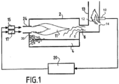
- the furnace is more specifically a rotary furnace for secondary lead melting with a combustion chamber 2 with a capacity of 15t.
- the furnace is equipped with a natural gas/oxygen burner 24 which generates the flame 11 in the combustion chamber 2.
- the power of the burner 24 and the oxygen/natural gas ratio are controlled by the furnace automation (control device 20 connected to the oxygen flow regulator 15 and to the natural gas flow regulator 17) according to the progress of the heating cycle, as described below.
- Charge 30 consists of lead waste from the crushing of automobile batteries. A significant portion of this lead is in the form of a "paste" of oxide (PbO, PbO 2 ”). and lead sulfate (PbSO 4 ). To this metallic charge are added materials necessary for the reduction of oxides partly made up of coke (containing a high carbon content), also called “reagents”.
- the lead recycling process involves heating the charge 30, and then keeping the charge hot in contact with the reactants in order to obtain liquid lead 4 and a slag which fixes the impurities and the sulfur present in the lead sulfate.
- the furnace operates discontinuously.
- the combustion chamber 2 is loaded at the beginning of each cycle.
- the burner 24 is then ignited and its power modulated by the control device 20 so that the temperature of the load follows a heating cycle that has been determined empirically.
- reaction rate of the carbon present in solid charge 30 with the furnace atmosphere varies depending on the different process parameters, such as in particular the composition of the load which varies depending on the origin of the batches to be recycled.
- the detection according to the invention by means of the UV detector 10 of the D-LX100 range marketed by the company Durag of the intensity of the combustion flame 12 of the CO + H 2 mixture with the dilution air just after the outlet 5 of the furnace makes it possible to correct the adjustment of the burner 24 by acting on the “Oxygen / Natural Gas” ratio. To this end, the detector 10 transmits to the control device 20 a signal corresponding to the detected flame intensity.
- the elbow of the chimney 13 and the positioning of the UV10 detector relative to said elbow ensures that the UV10 detector detects only the intensity of the flame 12 inside the chimney 13 without interference from the UV radiation of the combustion inside the combustion chamber 2.
- burner 24 injects an excess of 70 Nm3/h of oxygen, compared to the initial setting. This excess oxygen is then available for combustion inside furnace 2 of the combustible materials released by the load.
- This adjustment of the oxygen/natural gas ratio is done dynamically depending on the intensity of the post-combustion of the smoke in the chimney 13 (intensity of the flame 12 detected).
- furnace 2 The energy efficiency of furnace 2 is significantly improved and effective treatment of fumes, particularly their filtering, is ensured.
Landscapes
- Engineering & Computer Science (AREA)
- General Engineering & Computer Science (AREA)
- Mechanical Engineering (AREA)
- Environmental & Geological Engineering (AREA)
- Chemical & Material Sciences (AREA)
- Combustion & Propulsion (AREA)
- Metallurgy (AREA)
- Organic Chemistry (AREA)
- Materials Engineering (AREA)
- Manufacturing & Machinery (AREA)
- Waste-Gas Treatment And Other Accessory Devices For Furnaces (AREA)
- Incineration Of Waste (AREA)
- Control Of Combustion (AREA)
- Regulation And Control Of Combustion (AREA)
- Muffle Furnaces And Rotary Kilns (AREA)
- Manufacture And Refinement Of Metals (AREA)
Priority Applications (1)
| Application Number | Priority Date | Filing Date | Title |
|---|---|---|---|
| PL11719312T PL2561295T3 (pl) | 2010-04-23 | 2011-03-30 | Piec płomieniowy i sposób regulowania spalania w piecu płomieniowym |
Applications Claiming Priority (2)
| Application Number | Priority Date | Filing Date | Title |
|---|---|---|---|
| FR1053147A FR2959298B1 (fr) | 2010-04-23 | 2010-04-23 | Four a flamme et procede de regulation de la combustion dans un four a flamme |
| PCT/FR2011/050703 WO2011131880A1 (fr) | 2010-04-23 | 2011-03-30 | Four à flamme et procédé de régulation de la combustion dans un four à flamme |
Publications (3)
| Publication Number | Publication Date |
|---|---|
| EP2561295A1 EP2561295A1 (fr) | 2013-02-27 |
| EP2561295B1 EP2561295B1 (fr) | 2018-05-16 |
| EP2561295B2 true EP2561295B2 (fr) | 2025-04-02 |
Family
ID=43242840
Family Applications (1)
| Application Number | Title | Priority Date | Filing Date |
|---|---|---|---|
| EP11719312.8A Active EP2561295B2 (fr) | 2010-04-23 | 2011-03-30 | Four à flamme et procédé de régulation de la combustion dans un four à flamme |
Country Status (12)
| Country | Link |
|---|---|
| US (1) | US20130115560A1 (pl) |
| EP (1) | EP2561295B2 (pl) |
| JP (1) | JP2013530366A (pl) |
| CN (1) | CN102859307B (pl) |
| BR (1) | BR112012027190B1 (pl) |
| CA (1) | CA2797168C (pl) |
| ES (1) | ES2675910T5 (pl) |
| FR (1) | FR2959298B1 (pl) |
| PL (1) | PL2561295T3 (pl) |
| RU (1) | RU2012149939A (pl) |
| TR (1) | TR201809425T4 (pl) |
| WO (1) | WO2011131880A1 (pl) |
Families Citing this family (13)
| Publication number | Priority date | Publication date | Assignee | Title |
|---|---|---|---|---|
| EP2664884B1 (en) * | 2012-05-18 | 2019-08-07 | Air Products and Chemicals, Inc. | Method and apparatus for heating metals |
| CN103363540B (zh) * | 2013-06-21 | 2016-04-27 | 广东电网公司电力科学研究院 | 一种电站锅炉低负荷运行下的升温补燃系统 |
| DE102014013474A1 (de) * | 2014-09-11 | 2016-03-17 | Linde Aktiengesellschaft | Verfahren zur Abgasverbrennung mit Sauerstoffzuführung |
| JP6547690B2 (ja) * | 2016-06-13 | 2019-07-24 | トヨタ自動車株式会社 | ダイカスト戻し材の溶解方法 |
| DE102017007799A1 (de) * | 2017-08-17 | 2019-02-21 | Linde Aktiengesellschaft | Ofenanlage und Verfahren zum Betreiben eines Ofens |
| ES2904862T3 (es) * | 2018-03-02 | 2022-04-06 | Praxair Technology Inc | Análisis de imagen de llama para control de combustión de hornos |
| EP3715717B9 (fr) * | 2019-03-26 | 2021-11-24 | L'air Liquide, Societe Anonyme Pour L'etude Et L'exploitation Des Procedes Georges Claude | Procédé de combustion et brûleur pour sa mise en oeuvre |
| GB2588775A (en) * | 2019-11-05 | 2021-05-12 | Edwards Ltd | Optimising operating conditions in an abatement apparatus |
| CN111121872B (zh) * | 2019-12-27 | 2022-07-15 | 液化空气(中国)投资有限公司 | 一种能够实时监控、调节炉内燃烧状况的装置和方法 |
| CN112066407B (zh) * | 2020-09-11 | 2023-03-28 | 富士特锅炉(天津)有限公司 | 一种切向扩散耦合烟气外循环多元可调低氮燃烧设备 |
| EP4033149A1 (en) * | 2021-01-22 | 2022-07-27 | L'air Liquide, Societe Anonyme Pour L'etude Et L'exploitation Des Procedes Georges Claude | Monitoring combustible matter in a gaseous stream |
| CN114046501A (zh) * | 2021-11-16 | 2022-02-15 | 上海德律风置业有限公司 | 一种具有提高锅炉低氨燃烧装置 |
| EP4202297A1 (en) | 2021-12-21 | 2023-06-28 | L'Air Liquide, société anonyme pour l'Étude et l'Exploitation des procédés Georges Claude | Combustion process |
Citations (5)
| Publication number | Priority date | Publication date | Assignee | Title |
|---|---|---|---|---|
| EP0553632B1 (de) † | 1992-01-31 | 1996-11-27 | Linde Aktiengesellschaft | Geregelter Betrieb von Industrieöfen |
| US6247416B1 (en) † | 1998-04-02 | 2001-06-19 | L'air Liquide Societe Anonyme Pour L'etude Et L'exploitation Des Procedes Georges Claude | Method of operating a furnace and device for implementing the method |
| ES2207389A1 (es) † | 2001-11-16 | 2004-05-16 | Al Air Liquide España, S.A. | Mejoras en el objeto de la patente principal n.200102624, por "procedimiento para la fusion de una carga de aluminio". |
| WO2006117336A1 (fr) † | 2005-05-04 | 2006-11-09 | L'air Liquide, Societe Anonyme Pour L'etude Et L'exploitation Des Procedes Georges Claude | Procede de fusion d'une charge ferreuse |
| EP2159525A1 (de) † | 2008-08-29 | 2010-03-03 | Air Liquide Deutschland GmbH | Verfahren zum Betrieb eines Ofens sowie Vorrichtung zur Durchführung des Verfahrens |
Family Cites Families (58)
| Publication number | Priority date | Publication date | Assignee | Title |
|---|---|---|---|---|
| GB1079945A (en) * | 1964-07-24 | 1967-08-16 | Satchwell Controls Ltd | Improvements in flame supervision devices for burners |
| US3304989A (en) * | 1964-11-19 | 1967-02-21 | American Radiator & Standard | Fuel feed control system responsive to flame color |
| US3476945A (en) * | 1968-02-23 | 1969-11-04 | Bailey Meter Co | Flame detector for a multiple fuel-fired furnace |
| US3665440A (en) * | 1969-08-19 | 1972-05-23 | Teeg Research Inc | Fire detector utilizing ultraviolet and infrared sensors |
| CH537066A (de) * | 1971-04-08 | 1973-05-15 | Cerberus Ag | Flammen-Detektor |
| US4043742A (en) * | 1976-05-17 | 1977-08-23 | Environmental Data Corporation | Automatic burner monitor and control for furnaces |
| US4498861A (en) * | 1979-04-09 | 1985-02-12 | Kobe Steel, Limited | Method for controlling combustion in industrial furnaces |
| US4280184A (en) * | 1979-06-26 | 1981-07-21 | Electronic Corporation Of America | Burner flame detection |
| EP0064811B1 (en) * | 1981-04-16 | 1988-09-21 | EMI Limited | Flame detector |
| US4493635A (en) * | 1982-02-27 | 1985-01-15 | Osaka Gas Company Limited | Oxygen-enriched air ratio control device for combustion apparatus |
| US4477245A (en) * | 1982-09-03 | 1984-10-16 | The Babcock & Wilcox Company | Flame monitoring safety, energy and fuel conservation system |
| US4484947A (en) * | 1983-04-22 | 1984-11-27 | North American Manufacturing Company | Method for melting a charge of bulk solid metal |
| JPS60159515A (ja) * | 1984-01-27 | 1985-08-21 | Hitachi Ltd | 火炉システム |
| US4620491A (en) * | 1984-04-27 | 1986-11-04 | Hitachi, Ltd. | Method and apparatus for supervising combustion state |
| CN85201091U (zh) * | 1985-04-01 | 1986-03-26 | 张承辉 | 燃烧监测控制装置 |
| CN85101184B (zh) * | 1985-04-01 | 1988-11-30 | 株式会社日立制作所 | 燃烧系统 |
| GB2184584B (en) * | 1985-12-20 | 1989-10-25 | Graviner Ltd | Fire and explosion detection and suppression |
| JPH01244214A (ja) * | 1988-03-25 | 1989-09-28 | Agency Of Ind Science & Technol | バーナ運転空気比の監視制御方法および装置 |
| US4882573A (en) * | 1988-03-25 | 1989-11-21 | Pullman Canada Ltd. | Apparatus and method for detecting the presence of a burner flame |
| JPH01314809A (ja) * | 1988-06-14 | 1989-12-20 | Ishikawajima Harima Heavy Ind Co Ltd | 流動床式焼却炉の燃焼制御方法および装置 |
| US5113770A (en) * | 1991-06-10 | 1992-05-19 | Godbe Murray C | Apparatus for incinerating waste materials |
| US5222887A (en) * | 1992-01-17 | 1993-06-29 | Gas Research Institute | Method and apparatus for fuel/air control of surface combustion burners |
| US5480298A (en) * | 1992-05-05 | 1996-01-02 | General Electric Company | Combustion control for producing low NOx emissions through use of flame spectroscopy |
| EP0581451B1 (en) * | 1992-07-01 | 1996-10-30 | Toyota Jidosha Kabushiki Kaisha | Combustion control method |
| JPH0763311A (ja) * | 1993-08-27 | 1995-03-07 | Sanyo Electric Co Ltd | 焼却装置 |
| US5424554A (en) * | 1994-03-22 | 1995-06-13 | Energy Kenitics, Inc. | Oil-burner, flame-intensity, monitoring system and method of operation with an out of range signal discriminator |
| DE4428159C2 (de) * | 1994-08-09 | 1998-04-09 | Martin Umwelt & Energietech | Verfahren zur Regelung der Feuerung bei Verbrennungsanlagen, insbesondere Abfallverbrennungsanlagen |
| CN2243602Y (zh) * | 1995-02-09 | 1996-12-25 | 重庆华夏新技术发展有限公司 | 锅炉燃烧火焰检测装置 |
| JPH0989226A (ja) * | 1995-09-25 | 1997-04-04 | Hitachi Zosen Corp | 電気式灰溶融炉および電気式灰溶融炉における排ガスの燃焼方法 |
| JPH09178152A (ja) * | 1995-12-28 | 1997-07-11 | Hitachi Zosen Corp | 電気式灰溶融炉の排ガス燃焼部構造 |
| DE19615141A1 (de) * | 1996-04-17 | 1997-10-23 | Bfi Automation Gmbh | Verfahren und Einrichtung zur Steuerung eines Verbrennungsprozesses in einem Kessel |
| US5829962A (en) * | 1996-05-29 | 1998-11-03 | L'air Liquide, Societe Anonyme Pour L'etude Et, L'exploitation Des Procedes Georges | Method and apparatus for optical flame control of combustion burners |
| US6045353A (en) * | 1996-05-29 | 2000-04-04 | American Air Liquide, Inc. | Method and apparatus for optical flame control of combustion burners |
| JPH10110911A (ja) * | 1996-10-08 | 1998-04-28 | Nobuhiro Suzuki | 燃焼装置 |
| JP3607058B2 (ja) * | 1997-09-05 | 2005-01-05 | 三菱電機株式会社 | 焼却装置および焼却装置の運転制御方法 |
| JP3790979B2 (ja) * | 1997-09-08 | 2006-06-28 | 前島 文夫 | 有害物質除去焼却炉 |
| JPH11257637A (ja) * | 1998-03-11 | 1999-09-21 | Sanyo Electric Co Ltd | 焼却機の焼却バーナ用バーナファン制御方法 |
| JP3625639B2 (ja) * | 1998-03-19 | 2005-03-02 | 日立造船株式会社 | 流動床式焼却炉設備および流動床式焼却炉設備の燃焼制御方法 |
| JP3668010B2 (ja) * | 1998-09-29 | 2005-07-06 | 株式会社日立製作所 | ごみ焼却設備及びその制御方法 |
| JP2001004116A (ja) * | 1999-06-18 | 2001-01-12 | Mitsubishi Heavy Ind Ltd | 燃焼炉の燃焼制御方法及び燃焼制御装置 |
| JP3859926B2 (ja) * | 2000-01-24 | 2006-12-20 | 株式会社神鋼環境ソリューション | 熱分解ガス化溶融システムにおける燃焼用空気の制御方法及びその装置 |
| JP3806306B2 (ja) * | 2001-01-16 | 2006-08-09 | 三菱重工業株式会社 | 灰溶融炉の二次燃焼装置及び二次燃焼装置の運転方法 |
| US6404342B1 (en) * | 2001-09-14 | 2002-06-11 | Honeywell International Inc. | Flame detector using filtering of ultraviolet radiation flicker |
| FR2832732B1 (fr) | 2001-11-29 | 2004-02-13 | Air Liquide | Utilisation de l'analyse des fumees dans les fours d'aluminium |
| JP2003302022A (ja) * | 2002-04-10 | 2003-10-24 | Ebara Corp | 溶融炉、溶融炉の運転方法及びガス化溶融システム |
| JP2004012047A (ja) * | 2002-06-07 | 2004-01-15 | Jfe Engineering Kk | 焼却炉及び焼却炉の運転方法 |
| AU2003209925A1 (en) | 2003-03-21 | 2004-10-11 | L'air Liquide, Societe Anonyme A Directoire Et Conseil De Surveillance Pour L'etude Et L'exploitation Des Procedes Georges Claude | Process for melting an aluminum charge containing organic material |
| WO2005024398A1 (fr) | 2003-09-01 | 2005-03-17 | L'air Liquide, Societe Anonyme A Directoire Et Conseil De Surveillance Pour L'etude Et L'exploitation Des Procedes Georges Claude | Procede de mesure d'especes gazeuses par derivation |
| FR2866656B1 (fr) * | 2004-02-25 | 2006-05-26 | Air Liquide | Procede de traitement d'aluminium dans un four rotatif ou reverbere |
| JP2006046867A (ja) * | 2004-08-09 | 2006-02-16 | Miura Co Ltd | 燃焼システムの着火方法 |
| AU2005229668B2 (en) * | 2004-11-04 | 2008-03-06 | Babcock-Hitachi K.K. | Overfiring air port, method for manufacturing air port, boiler, boiler facility, method for operating boiler facility and method for improving boiler facility |
| CN100447484C (zh) * | 2005-07-08 | 2008-12-31 | 姜政华 | 一种以超细煤粉为主的多种燃料混烧的工业锅炉 |
| JP3963925B2 (ja) * | 2005-11-08 | 2007-08-22 | 株式会社神鋼環境ソリューション | 焼却処理システムにおける二次燃焼方法及び装置 |
| JP4701138B2 (ja) * | 2006-09-04 | 2011-06-15 | 三菱重工環境・化学エンジニアリング株式会社 | ストーカ式焼却炉及びその燃焼制御方法 |
| DE102006060869A1 (de) * | 2006-12-22 | 2008-06-26 | Khd Humboldt Wedag Gmbh | Verfahren zur Regelung des Betriebes eines Drehofenbrenners |
| JP5228511B2 (ja) * | 2008-02-07 | 2013-07-03 | 株式会社Ihi | 熱分解装置 |
| JP5243840B2 (ja) * | 2008-05-01 | 2013-07-24 | 株式会社タクマ | ストーカ式焼却炉の燃焼方法 |
| CN101655245B (zh) * | 2009-09-04 | 2011-03-16 | 江苏焱鑫科技股份有限公司 | 工业炉燃烧器多参数自动控制的方法 |
-
2010
- 2010-04-23 FR FR1053147A patent/FR2959298B1/fr active Active
-
2011
- 2011-03-30 PL PL11719312T patent/PL2561295T3/pl unknown
- 2011-03-30 CN CN201180020107.7A patent/CN102859307B/zh active Active
- 2011-03-30 RU RU2012149939/02A patent/RU2012149939A/ru not_active Application Discontinuation
- 2011-03-30 EP EP11719312.8A patent/EP2561295B2/fr active Active
- 2011-03-30 BR BR112012027190-3A patent/BR112012027190B1/pt active IP Right Grant
- 2011-03-30 ES ES11719312T patent/ES2675910T5/es active Active
- 2011-03-30 WO PCT/FR2011/050703 patent/WO2011131880A1/fr not_active Ceased
- 2011-03-30 JP JP2013505519A patent/JP2013530366A/ja not_active Ceased
- 2011-03-30 CA CA2797168A patent/CA2797168C/fr active Active
- 2011-03-30 TR TR2018/09425T patent/TR201809425T4/tr unknown
- 2011-03-30 US US13/642,683 patent/US20130115560A1/en not_active Abandoned
Patent Citations (5)
| Publication number | Priority date | Publication date | Assignee | Title |
|---|---|---|---|---|
| EP0553632B1 (de) † | 1992-01-31 | 1996-11-27 | Linde Aktiengesellschaft | Geregelter Betrieb von Industrieöfen |
| US6247416B1 (en) † | 1998-04-02 | 2001-06-19 | L'air Liquide Societe Anonyme Pour L'etude Et L'exploitation Des Procedes Georges Claude | Method of operating a furnace and device for implementing the method |
| ES2207389A1 (es) † | 2001-11-16 | 2004-05-16 | Al Air Liquide España, S.A. | Mejoras en el objeto de la patente principal n.200102624, por "procedimiento para la fusion de una carga de aluminio". |
| WO2006117336A1 (fr) † | 2005-05-04 | 2006-11-09 | L'air Liquide, Societe Anonyme Pour L'etude Et L'exploitation Des Procedes Georges Claude | Procede de fusion d'une charge ferreuse |
| EP2159525A1 (de) † | 2008-08-29 | 2010-03-03 | Air Liquide Deutschland GmbH | Verfahren zum Betrieb eines Ofens sowie Vorrichtung zur Durchführung des Verfahrens |
Non-Patent Citations (2)
| Title |
|---|
| "Apercu des produits technologie de la combustion", Durag Group (03/2006) † |
| "Capteurs de temperature a fibres optiques", Techniques de I'ingenieur (10/01/1989) † |
Also Published As
| Publication number | Publication date |
|---|---|
| JP2013530366A (ja) | 2013-07-25 |
| CN102859307A (zh) | 2013-01-02 |
| TR201809425T4 (tr) | 2018-07-23 |
| FR2959298A1 (fr) | 2011-10-28 |
| CN102859307B (zh) | 2015-08-19 |
| BR112012027190A2 (pt) | 2016-07-19 |
| ES2675910T5 (en) | 2025-05-30 |
| WO2011131880A1 (fr) | 2011-10-27 |
| EP2561295B1 (fr) | 2018-05-16 |
| ES2675910T3 (es) | 2018-07-13 |
| US20130115560A1 (en) | 2013-05-09 |
| PL2561295T3 (pl) | 2018-11-30 |
| CA2797168C (fr) | 2018-07-03 |
| CA2797168A1 (fr) | 2011-10-27 |
| RU2012149939A (ru) | 2014-05-27 |
| FR2959298B1 (fr) | 2012-09-21 |
| BR112012027190B1 (pt) | 2020-11-03 |
| EP2561295A1 (fr) | 2013-02-27 |
Similar Documents
| Publication | Publication Date | Title |
|---|---|---|
| EP2561295B2 (fr) | Four à flamme et procédé de régulation de la combustion dans un four à flamme | |
| EP3241808B1 (fr) | Procédé de combustion pour fusion de verre | |
| EP3087040B1 (fr) | Procédé et installation de combustion avec récupération d'énergie optimisée | |
| FR3132857A1 (fr) | Procédé de traitement autothermique de matériaux contenant un mélange de matières plastiques et de matières métalliques | |
| EP1913321B1 (fr) | Procede de calcination d'un materiau a faible emission de nox | |
| WO2005059440A1 (fr) | Procede de combustion etagee avec injection optimisee de l'oxydant primaire | |
| EP3715717B9 (fr) | Procédé de combustion et brûleur pour sa mise en oeuvre | |
| EP3087041B1 (fr) | Combustion avec récupération de chaleur ameliorée | |
| FR2640728A1 (fr) | Procede et appareil de reduction de la formation d'oxydes d'azote pendant une combustion | |
| CA2633019C (fr) | Procede d'oxycombustion etagee mettant en oeuvre des reactifs prechauffes | |
| EP0834049B1 (fr) | Procede de fusion d'une charge dans un four electrique a arc | |
| WO2006117336A1 (fr) | Procede de fusion d'une charge ferreuse | |
| EP0336087B1 (fr) | Procédé et installation pour le traitement d'un courant de gaz contenant de la poussière pyrophorique | |
| FR2969267A1 (fr) | Procede de fusion a chargement discontinu | |
| EP3813992B1 (fr) | Enrichissement en oxygène et combustion d'un combustible en forme de particules solides entraînées par un gaz porteur | |
| FR2977928A1 (fr) | Incinerateur de dechets tres energetiques | |
| EP2843309B1 (fr) | Procédé et installation de vitrification de déchets | |
| CN116293735A (zh) | 燃烧方法 | |
| EP3684735A1 (fr) | Procédé et dispositif de vitrification d'un matériau pulvérulent | |
| LU88533A1 (fr) | Procédé et dispositif de préchauffage de mitraille |
Legal Events
| Date | Code | Title | Description |
|---|---|---|---|
| PUAI | Public reference made under article 153(3) epc to a published international application that has entered the european phase |
Free format text: ORIGINAL CODE: 0009012 |
|
| 17P | Request for examination filed |
Effective date: 20121123 |
|
| AK | Designated contracting states |
Kind code of ref document: A1 Designated state(s): AL AT BE BG CH CY CZ DE DK EE ES FI FR GB GR HR HU IE IS IT LI LT LU LV MC MK MT NL NO PL PT RO RS SE SI SK SM TR |
|
| DAX | Request for extension of the european patent (deleted) | ||
| GRAP | Despatch of communication of intention to grant a patent |
Free format text: ORIGINAL CODE: EPIDOSNIGR1 |
|
| STAA | Information on the status of an ep patent application or granted ep patent |
Free format text: STATUS: GRANT OF PATENT IS INTENDED |
|
| INTG | Intention to grant announced |
Effective date: 20170927 |
|
| RIN1 | Information on inventor provided before grant (corrected) |
Inventor name: LOISELET, BENOIT Inventor name: BEAUDOIN, PHILIPPE |
|
| GRAJ | Information related to disapproval of communication of intention to grant by the applicant or resumption of examination proceedings by the epo deleted |
Free format text: ORIGINAL CODE: EPIDOSDIGR1 |
|
| STAA | Information on the status of an ep patent application or granted ep patent |
Free format text: STATUS: REQUEST FOR EXAMINATION WAS MADE |
|
| INTC | Intention to grant announced (deleted) | ||
| GRAP | Despatch of communication of intention to grant a patent |
Free format text: ORIGINAL CODE: EPIDOSNIGR1 |
|
| STAA | Information on the status of an ep patent application or granted ep patent |
Free format text: STATUS: GRANT OF PATENT IS INTENDED |
|
| INTG | Intention to grant announced |
Effective date: 20171208 |
|
| GRAS | Grant fee paid |
Free format text: ORIGINAL CODE: EPIDOSNIGR3 |
|
| GRAA | (expected) grant |
Free format text: ORIGINAL CODE: 0009210 |
|
| STAA | Information on the status of an ep patent application or granted ep patent |
Free format text: STATUS: THE PATENT HAS BEEN GRANTED |
|
| AK | Designated contracting states |
Kind code of ref document: B1 Designated state(s): AL AT BE BG CH CY CZ DE DK EE ES FI FR GB GR HR HU IE IS IT LI LT LU LV MC MK MT NL NO PL PT RO RS SE SI SK SM TR |
|
| REG | Reference to a national code |
Ref country code: GB Ref legal event code: FG4D Free format text: NOT ENGLISH |
|
| REG | Reference to a national code |
Ref country code: CH Ref legal event code: EP |
|
| REG | Reference to a national code |
Ref country code: IE Ref legal event code: FG4D Free format text: LANGUAGE OF EP DOCUMENT: FRENCH |
|
| REG | Reference to a national code |
Ref country code: DE Ref legal event code: R096 Ref document number: 602011048368 Country of ref document: DE |
|
| REG | Reference to a national code |
Ref country code: AT Ref legal event code: REF Ref document number: 999962 Country of ref document: AT Kind code of ref document: T Effective date: 20180615 |
|
| REG | Reference to a national code |
Ref country code: ES Ref legal event code: FG2A Ref document number: 2675910 Country of ref document: ES Kind code of ref document: T3 Effective date: 20180713 |
|
| REG | Reference to a national code |
Ref country code: NL Ref legal event code: MP Effective date: 20180516 |
|
| REG | Reference to a national code |
Ref country code: LT Ref legal event code: MG4D |
|
| PG25 | Lapsed in a contracting state [announced via postgrant information from national office to epo] |
Ref country code: BG Free format text: LAPSE BECAUSE OF FAILURE TO SUBMIT A TRANSLATION OF THE DESCRIPTION OR TO PAY THE FEE WITHIN THE PRESCRIBED TIME-LIMIT Effective date: 20180816 Ref country code: FI Free format text: LAPSE BECAUSE OF FAILURE TO SUBMIT A TRANSLATION OF THE DESCRIPTION OR TO PAY THE FEE WITHIN THE PRESCRIBED TIME-LIMIT Effective date: 20180516 Ref country code: NO Free format text: LAPSE BECAUSE OF FAILURE TO SUBMIT A TRANSLATION OF THE DESCRIPTION OR TO PAY THE FEE WITHIN THE PRESCRIBED TIME-LIMIT Effective date: 20180816 Ref country code: SE Free format text: LAPSE BECAUSE OF FAILURE TO SUBMIT A TRANSLATION OF THE DESCRIPTION OR TO PAY THE FEE WITHIN THE PRESCRIBED TIME-LIMIT Effective date: 20180516 Ref country code: LT Free format text: LAPSE BECAUSE OF FAILURE TO SUBMIT A TRANSLATION OF THE DESCRIPTION OR TO PAY THE FEE WITHIN THE PRESCRIBED TIME-LIMIT Effective date: 20180516 |
|
| PG25 | Lapsed in a contracting state [announced via postgrant information from national office to epo] |
Ref country code: LV Free format text: LAPSE BECAUSE OF FAILURE TO SUBMIT A TRANSLATION OF THE DESCRIPTION OR TO PAY THE FEE WITHIN THE PRESCRIBED TIME-LIMIT Effective date: 20180516 Ref country code: RS Free format text: LAPSE BECAUSE OF FAILURE TO SUBMIT A TRANSLATION OF THE DESCRIPTION OR TO PAY THE FEE WITHIN THE PRESCRIBED TIME-LIMIT Effective date: 20180516 Ref country code: HR Free format text: LAPSE BECAUSE OF FAILURE TO SUBMIT A TRANSLATION OF THE DESCRIPTION OR TO PAY THE FEE WITHIN THE PRESCRIBED TIME-LIMIT Effective date: 20180516 Ref country code: NL Free format text: LAPSE BECAUSE OF FAILURE TO SUBMIT A TRANSLATION OF THE DESCRIPTION OR TO PAY THE FEE WITHIN THE PRESCRIBED TIME-LIMIT Effective date: 20180516 Ref country code: GR Free format text: LAPSE BECAUSE OF FAILURE TO SUBMIT A TRANSLATION OF THE DESCRIPTION OR TO PAY THE FEE WITHIN THE PRESCRIBED TIME-LIMIT Effective date: 20180817 |
|
| REG | Reference to a national code |
Ref country code: AT Ref legal event code: MK05 Ref document number: 999962 Country of ref document: AT Kind code of ref document: T Effective date: 20180516 |
|
| PG25 | Lapsed in a contracting state [announced via postgrant information from national office to epo] |
Ref country code: RO Free format text: LAPSE BECAUSE OF FAILURE TO SUBMIT A TRANSLATION OF THE DESCRIPTION OR TO PAY THE FEE WITHIN THE PRESCRIBED TIME-LIMIT Effective date: 20180516 Ref country code: DK Free format text: LAPSE BECAUSE OF FAILURE TO SUBMIT A TRANSLATION OF THE DESCRIPTION OR TO PAY THE FEE WITHIN THE PRESCRIBED TIME-LIMIT Effective date: 20180516 Ref country code: AT Free format text: LAPSE BECAUSE OF FAILURE TO SUBMIT A TRANSLATION OF THE DESCRIPTION OR TO PAY THE FEE WITHIN THE PRESCRIBED TIME-LIMIT Effective date: 20180516 Ref country code: EE Free format text: LAPSE BECAUSE OF FAILURE TO SUBMIT A TRANSLATION OF THE DESCRIPTION OR TO PAY THE FEE WITHIN THE PRESCRIBED TIME-LIMIT Effective date: 20180516 Ref country code: CZ Free format text: LAPSE BECAUSE OF FAILURE TO SUBMIT A TRANSLATION OF THE DESCRIPTION OR TO PAY THE FEE WITHIN THE PRESCRIBED TIME-LIMIT Effective date: 20180516 Ref country code: SK Free format text: LAPSE BECAUSE OF FAILURE TO SUBMIT A TRANSLATION OF THE DESCRIPTION OR TO PAY THE FEE WITHIN THE PRESCRIBED TIME-LIMIT Effective date: 20180516 |
|
| REG | Reference to a national code |
Ref country code: DE Ref legal event code: R026 Ref document number: 602011048368 Country of ref document: DE |
|
| PLAZ | Examination of admissibility of opposition: despatch of communication + time limit |
Free format text: ORIGINAL CODE: EPIDOSNOPE2 |
|
| PLBI | Opposition filed |
Free format text: ORIGINAL CODE: 0009260 |
|
| PG25 | Lapsed in a contracting state [announced via postgrant information from national office to epo] |
Ref country code: SM Free format text: LAPSE BECAUSE OF FAILURE TO SUBMIT A TRANSLATION OF THE DESCRIPTION OR TO PAY THE FEE WITHIN THE PRESCRIBED TIME-LIMIT Effective date: 20180516 |
|
| PLBA | Examination of admissibility of opposition: reply received |
Free format text: ORIGINAL CODE: EPIDOSNOPE4 |
|
| PLAX | Notice of opposition and request to file observation + time limit sent |
Free format text: ORIGINAL CODE: EPIDOSNOBS2 |
|
| 26 | Opposition filed |
Opponent name: LINDE AKTIENGESELLSCHAFT Effective date: 20190214 |
|
| PG25 | Lapsed in a contracting state [announced via postgrant information from national office to epo] |
Ref country code: SI Free format text: LAPSE BECAUSE OF FAILURE TO SUBMIT A TRANSLATION OF THE DESCRIPTION OR TO PAY THE FEE WITHIN THE PRESCRIBED TIME-LIMIT Effective date: 20180516 |
|
| PLBB | Reply of patent proprietor to notice(s) of opposition received |
Free format text: ORIGINAL CODE: EPIDOSNOBS3 |
|
| PG25 | Lapsed in a contracting state [announced via postgrant information from national office to epo] |
Ref country code: MC Free format text: LAPSE BECAUSE OF FAILURE TO SUBMIT A TRANSLATION OF THE DESCRIPTION OR TO PAY THE FEE WITHIN THE PRESCRIBED TIME-LIMIT Effective date: 20180516 |
|
| REG | Reference to a national code |
Ref country code: CH Ref legal event code: PL |
|
| PG25 | Lapsed in a contracting state [announced via postgrant information from national office to epo] |
Ref country code: AL Free format text: LAPSE BECAUSE OF FAILURE TO SUBMIT A TRANSLATION OF THE DESCRIPTION OR TO PAY THE FEE WITHIN THE PRESCRIBED TIME-LIMIT Effective date: 20180516 Ref country code: LU Free format text: LAPSE BECAUSE OF NON-PAYMENT OF DUE FEES Effective date: 20190330 |
|
| REG | Reference to a national code |
Ref country code: BE Ref legal event code: MM Effective date: 20190331 |
|
| PG25 | Lapsed in a contracting state [announced via postgrant information from national office to epo] |
Ref country code: IE Free format text: LAPSE BECAUSE OF NON-PAYMENT OF DUE FEES Effective date: 20190330 Ref country code: LI Free format text: LAPSE BECAUSE OF NON-PAYMENT OF DUE FEES Effective date: 20190331 Ref country code: CH Free format text: LAPSE BECAUSE OF NON-PAYMENT OF DUE FEES Effective date: 20190331 |
|
| PG25 | Lapsed in a contracting state [announced via postgrant information from national office to epo] |
Ref country code: BE Free format text: LAPSE BECAUSE OF NON-PAYMENT OF DUE FEES Effective date: 20190331 |
|
| PLAB | Opposition data, opponent's data or that of the opponent's representative modified |
Free format text: ORIGINAL CODE: 0009299OPPO |
|
| R26 | Opposition filed (corrected) |
Opponent name: LINDE GMBH Effective date: 20190214 |
|
| PG25 | Lapsed in a contracting state [announced via postgrant information from national office to epo] |
Ref country code: PT Free format text: LAPSE BECAUSE OF FAILURE TO SUBMIT A TRANSLATION OF THE DESCRIPTION OR TO PAY THE FEE WITHIN THE PRESCRIBED TIME-LIMIT Effective date: 20180917 Ref country code: MT Free format text: LAPSE BECAUSE OF FAILURE TO SUBMIT A TRANSLATION OF THE DESCRIPTION OR TO PAY THE FEE WITHIN THE PRESCRIBED TIME-LIMIT Effective date: 20180516 |
|
| PG25 | Lapsed in a contracting state [announced via postgrant information from national office to epo] |
Ref country code: CY Free format text: LAPSE BECAUSE OF FAILURE TO SUBMIT A TRANSLATION OF THE DESCRIPTION OR TO PAY THE FEE WITHIN THE PRESCRIBED TIME-LIMIT Effective date: 20180516 |
|
| PG25 | Lapsed in a contracting state [announced via postgrant information from national office to epo] |
Ref country code: IS Free format text: LAPSE BECAUSE OF FAILURE TO SUBMIT A TRANSLATION OF THE DESCRIPTION OR TO PAY THE FEE WITHIN THE PRESCRIBED TIME-LIMIT Effective date: 20180916 |
|
| PG25 | Lapsed in a contracting state [announced via postgrant information from national office to epo] |
Ref country code: HU Free format text: LAPSE BECAUSE OF FAILURE TO SUBMIT A TRANSLATION OF THE DESCRIPTION OR TO PAY THE FEE WITHIN THE PRESCRIBED TIME-LIMIT; INVALID AB INITIO Effective date: 20110330 |
|
| PLCK | Communication despatched that opposition was rejected |
Free format text: ORIGINAL CODE: EPIDOSNREJ1 |
|
| APAH | Appeal reference modified |
Free format text: ORIGINAL CODE: EPIDOSCREFNO |
|
| APBM | Appeal reference recorded |
Free format text: ORIGINAL CODE: EPIDOSNREFNO |
|
| APBP | Date of receipt of notice of appeal recorded |
Free format text: ORIGINAL CODE: EPIDOSNNOA2O |
|
| APBQ | Date of receipt of statement of grounds of appeal recorded |
Free format text: ORIGINAL CODE: EPIDOSNNOA3O |
|
| PG25 | Lapsed in a contracting state [announced via postgrant information from national office to epo] |
Ref country code: MK Free format text: LAPSE BECAUSE OF FAILURE TO SUBMIT A TRANSLATION OF THE DESCRIPTION OR TO PAY THE FEE WITHIN THE PRESCRIBED TIME-LIMIT Effective date: 20180516 |
|
| P01 | Opt-out of the competence of the unified patent court (upc) registered |
Effective date: 20230523 |
|
| APBU | Appeal procedure closed |
Free format text: ORIGINAL CODE: EPIDOSNNOA9O |
|
| APAN | Information on closure of appeal procedure modified |
Free format text: ORIGINAL CODE: EPIDOSCNOA9O |
|
| PUAH | Patent maintained in amended form |
Free format text: ORIGINAL CODE: 0009272 |
|
| STAA | Information on the status of an ep patent application or granted ep patent |
Free format text: STATUS: PATENT MAINTAINED AS AMENDED |
|
| 27A | Patent maintained in amended form |
Effective date: 20250402 |
|
| AK | Designated contracting states |
Kind code of ref document: B2 Designated state(s): AL AT BE BG CH CY CZ DE DK EE ES FI FR GB GR HR HU IE IS IT LI LT LU LV MC MK MT NL NO PL PT RO RS SE SI SK SM TR |
|
| REG | Reference to a national code |
Ref country code: DE Ref legal event code: R102 Ref document number: 602011048368 Country of ref document: DE |
|
| PGFP | Annual fee paid to national office [announced via postgrant information from national office to epo] |
Ref country code: DE Payment date: 20250319 Year of fee payment: 15 |
|
| PGFP | Annual fee paid to national office [announced via postgrant information from national office to epo] |
Ref country code: FR Payment date: 20250325 Year of fee payment: 15 Ref country code: PL Payment date: 20250321 Year of fee payment: 15 |
|
| PGFP | Annual fee paid to national office [announced via postgrant information from national office to epo] |
Ref country code: IT Payment date: 20250320 Year of fee payment: 15 Ref country code: GB Payment date: 20250321 Year of fee payment: 15 |
|
| PGFP | Annual fee paid to national office [announced via postgrant information from national office to epo] |
Ref country code: TR Payment date: 20250324 Year of fee payment: 15 |
|
| REG | Reference to a national code |
Ref country code: ES Ref legal event code: DC2A Ref document number: 2675910 Country of ref document: ES Kind code of ref document: T5 Effective date: 20250530 |
|
| PGFP | Annual fee paid to national office [announced via postgrant information from national office to epo] |
Ref country code: ES Payment date: 20250428 Year of fee payment: 15 |