EP2559112B1 - Elektrisches steckverbindungselement und steckverbindungsteil mit mehreren steckverbindungselementen - Google Patents
Elektrisches steckverbindungselement und steckverbindungsteil mit mehreren steckverbindungselementen Download PDFInfo
- Publication number
- EP2559112B1 EP2559112B1 EP11714943.5A EP11714943A EP2559112B1 EP 2559112 B1 EP2559112 B1 EP 2559112B1 EP 11714943 A EP11714943 A EP 11714943A EP 2559112 B1 EP2559112 B1 EP 2559112B1
- Authority
- EP
- European Patent Office
- Prior art keywords
- contact
- plug
- section
- connection element
- connection
- Prior art date
- Legal status (The legal status is an assumption and is not a legal conclusion. Google has not performed a legal analysis and makes no representation as to the accuracy of the status listed.)
- Active
Links
Images


Classifications
-
- H—ELECTRICITY
- H01—ELECTRIC ELEMENTS
- H01R—ELECTRICALLY-CONDUCTIVE CONNECTIONS; STRUCTURAL ASSOCIATIONS OF A PLURALITY OF MUTUALLY-INSULATED ELECTRICAL CONNECTING ELEMENTS; COUPLING DEVICES; CURRENT COLLECTORS
- H01R13/00—Details of coupling devices of the kinds covered by groups H01R12/70 or H01R24/00 - H01R33/00
- H01R13/02—Contact members
- H01R13/10—Sockets for co-operation with pins or blades
- H01R13/11—Resilient sockets
- H01R13/112—Resilient sockets forked sockets having two legs
-
- H—ELECTRICITY
- H01—ELECTRIC ELEMENTS
- H01R—ELECTRICALLY-CONDUCTIVE CONNECTIONS; STRUCTURAL ASSOCIATIONS OF A PLURALITY OF MUTUALLY-INSULATED ELECTRICAL CONNECTING ELEMENTS; COUPLING DEVICES; CURRENT COLLECTORS
- H01R13/00—Details of coupling devices of the kinds covered by groups H01R12/70 or H01R24/00 - H01R33/00
- H01R13/02—Contact members
- H01R13/10—Sockets for co-operation with pins or blades
- H01R13/14—Resiliently-mounted rigid sockets
Definitions
- the invention relates to an electrical plug connection element and a plug connection part with a plurality of such plug connection elements.
- a plug element and a socket element is plugged together in electrical connectors, wherein the contact elements of the plug element and the socket element come into electrical contact with each other and is guided over the contact surfaces thus produced the electric current.
- Known connectors provide slotted contacts in which two contact surfaces between pin and socket are formed by a slot. Also known is the embodiment with two slots, are formed by the four contact surfaces. A higher number of contact surfaces results from the use of so-called lamellar contacts. In this case, for example, punched fins are mounted in a contact carrier. Due to the large number of contact surfaces results in a high contact reliability.
- a plug connection element with a contact member which has at least one line contact, by means of which the contact member when mating with a associated connecting element is electrically connected.
- the achievable contact and current carrying properties are already very good.
- the invention has for its object to provide a connector element and a connector part with a plurality of such connector elements, which have even further improved performance characteristics over the known connector elements or connector parts.
- a high contact reliability and high current carrying capacity is to be ensured with simple plug-in, in particular, the connector element and the connector part should be insensitive to mechanical and / or thermal stress.
- the connector element has at least two contact plates formed by shaped electrically conductive sheet metal strips, each having a connection portion for the electrical connection of the connector element to an electrical line to be connected and a contact portion for releasably connecting the electrical connector element with an associated connecting element and between the terminal portion and the contact portion arranged compensating portion for an elastic deflection of the contact portion relative to the terminal portion, wherein the terminal portion, the compensation portion and the contact portion are each formed integrally of the metal strips.
- the elastic deflection provided by the compensating section is advantageous in the assembled state of the two plug connection parts, because this compensates for deviations in the position of the contact pins in the assembled plug-in system and does not lead to a reduced contact input and thus to a reduced current carrying capacity. Occurring vibrations can be absorbed by the strain relief described below. Due to the provided insertion bevels and / or contact surfaces and / or the over-spring the forces required for insertion and removal are adjustable.
- the three sections are arranged one behind the other in a longitudinal direction of the plug connection element and can provide the respectively assigned function without negatively influencing each other. All three sections are integrally formed by one or more contact plates, so that contact points are avoided, for example between the terminal portion and the contact portion.
- the contact plates form the contact element of the connector element. Due to the compensating section, the contact sheets have sufficient flexibility despite a comparatively large cross-sectional area which offers high current carrying capacity. Therefore, the contact plates directly, ie without interposition of a contact-making body, in contact with the contact organ of the associated Plug connection part are brought. It thus eliminates a required in the prior art at high current carrying capacity additional contact point at the transition of the contact member to a continuing section within the connector element. Therefore, the connector element according to the invention not only has a high current carrying capacity, but also has an improved vibration resistance.
- the material for the contact sheets is preferably pure copper to minimize the total resistance of the connector element.
- the material used is preferably oxygen-poor or oxygen-free copper.
- embrittlement of the contact sheets can be prevented even at relatively high temperatures, as can be achieved, for example, when using connector elements according to the invention in motor vehicle technology, in particular in hydrogen-powered vehicles.
- the contact portion or preferably the entire contact plate may have a surface coating, for example made of silver or another noble metal, in order to reduce the contact resistance even at high mating cycles.
- the contact plates are enclosed in the connection section by an at least partially sleeve-shaped connecting element, by means of which the contact plates are fixed in their position relative to one another in an initial state.
- the contact sheets can be bent partially circularly in the connection section, in particular approximately semicircular, when two contact plates are used, so that a fixation of the contact plates results solely in the insertion of the connection section of the two contact plates into the connection element.
- the connecting element When connecting the electrical line, a crimped connection of the contact plates to the electrical line is produced by means of the connecting element.
- the connecting element preferably has an insertion bevel.
- the connecting element preferably also consists of comparatively soft copper.
- a hexagonal crimping is performed to improve the contact characteristics and to provide a permanently secure mechanical connection between the male connector and the electrical lead.
- the sleeve extends beyond the crimp area.
- the connecting element in one embodiment has a supporting element, for example a one-stage or multi-stage, in particular two-stage, annular flange with which the connecting element can alternatively or additionally also be supported on a housing of the associated plug connection part.
- At least one of the contact plates in the compensating section has a reduced flexural rigidity. This can for example by one or more recesses in the wall thickness and / or provided by one or more lateral cuts in the stripe width of the contact sheets. As a result, a desired articulation point is created, which enables a deflection of the contact section with respect to the connection section with a comparatively small force. As a result, low insertion forces can be realized in a particularly advantageous manner and / or, above all, a compensation of temperature-induced expansion states of the interacting components, which consist of different materials. Because the contact plate is fixed in the crimp region, an elasticity of the plug connection element can be provided by the compensation region, which ensures optimal contact in the contact section despite manufacturing tolerances.
- At least one contact plate, preferably all, and in particular both contact plates, of the plug connection element are bent meandering in the compensating section or in any case are bent.
- the contact sheets can be deflected with relatively little effort such that mating of the connector element with an associated connecting element and the release of such a connector with little effort are possible.
- the meandering compensating section the two sections running parallel to each other legs at a distance from each other. This ensures a movement play when deflecting.
- the rigidity of the contact plate may be reduced, for example by a material recess, and in particular by a local reduction of the width of the contact plate.
- At least one contact plate in the compensation section has a preferably integrally formed stop means in order to limit the deflection of the contact section with respect to the connection section.
- a lateral extension may be bent in the direction of the opposite leg. At a maximum deflection of the bent portion comes into contact with the opposite leg, whereby the deflection is limited.
- At least one contact plate in the contact portion has a cross-sectional shape that deviates from the cross-sectional shape of a contact member of the associated connecting element; As a result, two electrical line contacts are formed when mating with the associated connecting element.
- at least one contact plate of the contact portion is bent in a V-shape or U-shape. When mating the connector element with the associated connecting element thereby two electrical line contacts are formed by each contact plate. In one embodiment, in which the connector element has two contact plates, thereby a total of four electrical line contacts are formed.
- the length of the line contacts is limited by the length of the V-shaped or U-shaped bent contact sheets in the contact portion. In one embodiment, this length is between 2 and 20 mm, in particular between 4 and 15 mm and preferably between 6 and 10 mm. This makes it possible, for example, to provide a short-circuit current carrying capacity of 3,000 A for the duration of 1 s.
- the contact plates in the contact section form a plug-in receptacle for a pin-shaped contact element of the associated connecting element, for example.
- the longitudinal axis of the plug-in receptacle and thus the plug-in direction can be aligned longitudinally or obliquely and in particular transversely to the longitudinal direction of the plug connection element, in which the contact section, the compensating section and the connection section are arranged one behind the other.
- a foreign spring is arranged in the contact portion, with which the contact plates are durable in contact-bearing contact with the associated connecting element.
- the foreign spring may be made of a spring steel with suitable elastic materials, in particular, no special electrical properties are required.
- the foreign spring is made of a non-magnetizable material. The foreign spring is outside the current path, so that an electrical contact takes place only between the contact portion of the contact plate and the contact member of the associated connecting element.
- the foreign spring has an annular portion which limits the maximum expansion of the contact plates in the contact portion. From the annular portion spring arms can protrude, in particular in the direction of the associated connecting element facing the end of the contact plate, which apply the required contact force. The spring arms can be bent radially inward to be held in contact with the contact plates. The number of spring arms can match the number of contact plates or a multiple of the number of contact plates.
- the foreign spring on guide means by means of which the foreign spring in a extending in the insertion direction recess between the contact plates is attachable to the contact plates.
- the guide means can also protrude in the insertion direction of the annular portion of the foreign spring and be bent radially inward.
- the stop means may in particular be arranged at the transition from the V-shaped or U-shaped contact section to the meander of the compensation section.
- the invention also relates to a plug connection part with a plurality of plug connection elements according to the invention as described above, wherein the plug connection elements are arranged as identical parts in a common housing of the plug connection part.
- multi-pin plug connection parts in the manner of a modular system can be equipped with connector elements according to the invention.
- the individual plug connection elements of a plug connection part can be constructed completely identical and also have identical dimensions.
- the connector part can accommodate differently dimensioned connector elements, for example, for different high load currents.
- the connector element according to the invention can be scaled for different rated currents.
- the contact sheet at a width of 8 mm can have a thickness of 0.8 mm, and in the connection section lines or cables with a cross-sectional area of 16 to 25 mm 2 can be connected.
- the contact plate may have a thickness of 1.0 mm at a width of 12 mm, and in the connection section, lines or cables with a cross-sectional area of 35 to 50 mm 2 may be connected.
- the contact plate can have a thickness of 1.25 mm at a width of 16 mm, and cables or cables with a cross-sectional area of 70 to 95 mm 2 can be connected in the connection section.
- the connector elements are designed for electrical voltages in the range of more than 12 V and less than 2400 V, in particular more than 24 V and less than 1000 V and preferably up to an operating voltage of 700 V.
- the connector parts in used in vehicle technology, especially in electric or hybrid vehicles or electric power machines.
- the Fig. 1 shows a perspective view of a first embodiment of a connector system 1 with a first connector part 2 and a second connector part 4 in not yet mated condition.
- the first connector part 2 is designed as a three-pole plug, with the three each unipolar electrical lines 6, which are each designed as a cable with a cable sheath, are electrically connected to the second connector part 4.
- a housing 48 for example, in the Fig. 17 and 18 arranged socket-shaped contact members, which are brought into electrical contact upon mating of the first and second connector part 2, 4 with preferably cylindrical contact pins 22 in the second connector part 4.
- the second connector part 4 is arranged in the exemplary embodiment on a housing wall 8 of an aggregate, for example on an alternator or on an electric motor.
- the first and second connector part 2, 4 each have three load contacts 12, 14, 16, which serve for an electrical connection of the electrical lines 6, and a pilot contact 18 of the in the Fig. 1 only the associated pilot contact of the second connector part 4 is partially visible.
- the two connector parts 2, 4 also have components 20 for a guide of the first connector part 2 when mating with the second connector part 4, wherein on the part of the second connector part 4 as a guide component at least partially cylindrical pin 24 is arranged, at its the first connector part 2 facing end is tapered, in particular rounded and / or has a conical surface.
- the two connector parts 2, 4 components for locking the first connector part 2 on the second connector part 4 which has a connecting screw 26 in the embodiment on the side of the first connector part 2 and on the part of second connector part 4 a threaded bore 28.
- the second connector part 4 is preferably releasably secured by means of a terminal block 30 on the housing wall 8, screwed in the embodiment.
- the first connector part 2 has a wiring running parallel to the plug-in direction.
- the Fig. 2 shows a second embodiment of a connector system 1, wherein the first connector part 102 has an angled to the direction of insertion extending wiring of the electrical lines 6, in particular an angled 90 ° cable routing.
- the second connector part 4 is identical to the second connector part 4 of the first embodiment of the Fig. 1 constructed, in particular, both a first connector part 2 extending parallel to the plug direction wiring, as in the Fig. 1 shown, as well as a first connector part 102 with angled to the direction of insertion extending wiring with the same second connector part 4 can be plugged together.
- the components of a first component group with components for the pilot contact 18, and the components for the three load contacts 12, 14, 16 are independent of a number of load contacts 12, 14, 16 determined pole number of the first connector part 102, in particular, the pilot contact 18th always identical, regardless of whether it is a one-, two- or n-pin connector; the same applies to the load contacts 12, 14, 16 in the straight version and the load contacts 212, 214 in the angled design ( Fig. 3 ).
- the components 20 for a guide during mating and the components 26 for fixing the first connector part 2 to the second connector part 4 are formed independently of the number of poles.
- the housing 48 of the first connector part 2 has one of the number of load contacts 12, 14, 16 certain number of poles determined number of receiving chambers for the components of the load contacts 12, 14, 16.
- the arranged within the housing 48 components of the load contacts 12, 14, 16 are constructed identically.
- the components 20 for guiding the mating, as well as the components of the pilot contact 18 and the attachment 26 are between the in the Fig. 1 and 2 arranged on the left arranged first load contact 12 and the middle load contact 14. In one embodiment, this arrangement is maintained even with two- or multi-pin connectors, In particular, the arrangement of the components 20 for the guide, the pilot contact 18 and the connecting means 26 is always independent of the number of poles of the connector system 1 between two adjacent load contacts 12, 14 are arranged.
- the second connector part 4 has a contact pin 22 in the axial direction superior sleeve-shaped portion 32 which can serve for further guidance of the first connector part 2, 102 when mating with the second connector part 4.
- the sleeve-shaped portion 32 has an opening 34 extending in the plug-in direction, which is open in the direction of the first plug connection part 2, 102 and in the exemplary embodiment is formed by a slot.
- the first connector part 2, 102 projects with its housing 48 beyond an end 36 of the opening 34 facing the second connector part 4. This is followed by an annular and preferably cylindrical or conical section 38, to which a sealing means can be brought into abutment in the assembled state and thereby seals the contact elements of the connector system 1.
- the sleeve-shaped portion 32 preferably integrally formed guide means 40, which extend in the embodiment in the axial direction and are formed as webs, and by the mating a further guidance and / or reverse polarity is guaranteed.
- the guide means or webs and the associated recesses may form a customizable coding of the connector system 1.
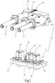
- the Fig. 3 shows a perspective view of a third embodiment of a connector system 201 with a two-pole first connector part 202 and a two-pole second connector part 204, wherein the first connector part 202 is an angled connector, in which the wiring runs perpendicular to the direction of insertion.
- the Fig. 4 shows a side view of the connector system 201 of Fig. 3
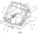
- the Fig. 5 shows in a opposite the 3 and 4 enlarged view of a perspective view of the connector system 201 in a partially separated state.
- the first connector part 202 has a bow-shaped actuating element 242, with which the two connector parts 202, 204 from the in the 3 and 4 fully assembled state in one in the Fig. 5 illustrated state in which the pilot contact 218 is either already separated, or at least in a complete transfer of the actuating element 242 in a relation to the representation in the 3 and 4 is rotated by 90 ° position, the load contacts 212, 214 but still electrically connected.
- the actuating element 242 is pivotable about a preferably integrally formed by the first connector part 202 axle journal 244, whereupon a introduced in the actuator 242, for example, by a groove cam 246 is moved along a arranged on the second connector part 204 guide pin 250 such that the first connector part 202th lifts from the second connector part 204.
- the actuator 242 can in his in the 3 and 4 shown first end position and / or in a contrast rotated by 90 ° second end position releasably be locked. Due to the lever action of the actuating element 242, only a small actuating force is required both when opening and when closing the connection between the first and the second plug connection part 202, 204. This is particularly advantageous at high temperatures and / or soiling environmental conditions.
- the first plug connection part 202 and the second plug connection part 204 have mutually corresponding latching means 252, 254, wherein in the exemplary embodiment the latching means 252 of the first plug connection part 202 is formed by a recess in a housing wall, in which engages the corresponding latching means 254 of the second plug connection part 204 when plugging while locked with the opening.
- the locking means 254 of the second connector part 204 has a run-on slope, by means of which the locking means 254 is deflected during mating and snaps back as soon as the locking means 254 engages in the opening in the first connector part 202.
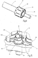
- the Fig. 6 shows a perspective view of an enlarged detail in the region of the locking means 252, 254 in a state in which the first connector part 202 are completely mated with the second connector part 204 and both the load contacts 212, 214 and the pilot contact 218 are closed.
- the Fig. 7 shows an enlarged section in the region of the latching elements 252, 254 in a state in which the first connector part 202 so far from the second connector part 204 is released that the pilot contact 218 is disconnected, the load contacts 212, 214 but still connected.
- the latching element 252 of the first plug connection part has a first opening section 256 which is slightly larger than a first section 258 of the second latching element 254 but smaller than a second section 260 of the second latching element 254 Fig. 7
- the second portion 260 shown in abutment against the housing 48 of the first connector part 2 and blocks a complete removal of the first connector part 202 of the second connector part 204. Only by a deflection of the second locking element 254, for example by means of a tool, the second portion 260 in Covering with a second, opposite the first opening portion larger second opening portion 262 of the first locking element 254 brought slightly larger than the second portion 260 of the second locking element 254, so that the first connector part 202 can be removed from the second connector part 204.
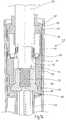
- the Fig. 8 shows a section of a section through the housing 48 of the first connector part 2 in a region in which the electrical line 6 shown in a view is connected to the first connector part 2.
- the cable 6 is a cable with an inner conductor 53, which is surrounded by an insulation 55, on the outside of a metallic conductive cable shield 57 is applied.
- the inner conductor 53 is provided with an electrical plug connection element 10 (described below). Fig. 17 . 18 ) electrically and mechanically connected.
- the connector part 2 which is a device 11 for electrically connecting the cable shield 57 of the electrical line 6 to the housing 48, further comprises a three-part fixing in the illustrated embodiment 81, 85, 87, by means of which the connecting element 78 and thus the inner conductor 53 at Occurrence of a tensile force on the line 6 is fixed immovably in the housing 48 by positive engagement.
- the connecting element 78 is at least partially sleeve-shaped and mechanically fixedly connected by clamping with the inner conductor 53, in particular with the inner conductor 53 pressed. The pressing takes place with the interposition of two contact plates 72, 74, which also form the contact member of the connector element 10 in one piece.
- the connecting element 78 has at least one end on a flange-like widening 84, which forms a form of a positive connection in the direction of the tensile force and preferably annular contact surface 79 for a first part 81 of the fixing.
- the first part 81 of the fixing element is sleeve-shaped and surrounds the Connecting element 78 and extends in the direction of an end facing away from the contact element of the connector element 10 beyond the connecting element 78 addition.
- the first part 81 of the fixing element with the interposition of a radially outwardly extending connecting line 83 for the cable shield 57 in contact with a second part 85 of the fixing, which is also sleeve-shaped and the line 6 receives in itself.
- the second part 85 has a contact surface for a third part 87 of the fixing element, which forms a positive connection with the housing 48 in the direction of the tensile force.
- the third part 87 of the fixing element is clamp-shaped in the exemplary embodiment, wherein the associated clip in a designated opening 89 (FIG. Fig. 1 ) is inserted into the housing 48 in a direction obliquely and in particular transversely to the direction of insertion or to the longitudinal direction of the line 6 and thereby locks the fixing element in the housing 48.
- this tensile force is transmitted via the inner conductor 53 to the connecting element 78, which in positive engagement with the first part 81 of the fixing, this in turn in positive engagement with the second part 85, and this in turn in positive engagement on the third part 87, wherein the third part 87 is in positive engagement with the housing 48.
- a firm connection between the conduit 6 and the housing 48 is provided, which is based only on positive engagement and is independent of frictional forces.
- the device 11 is part of a receiving chamber associated with each pole for each load contact 12, 14, 16, 212, 214 in each embodiment of the housing 48 of the first connector part 2.
- the device 11 may be formed the same for both straight connector and angled connectors except for the formation of the contact members.
- the device 11 also has an intermediate element 91, which may be made of a plastic.
- the intermediate element 91 can also be referred to as insulating sleeve.
- the intermediate element 91 comprises the connecting element 78 at least in sections and projects in the direction of the contact element of the plug connection element 10 beyond the connecting element 78.
- the intermediate member 91 integrally forms a sleeve-shaped guide portion 75 which upon mating of the first and second connector part 2, 4 in abutment against the sleeve-shaped portion 32 (FIGS. Fig. 1 ) of the second connector part 4 comes and is guided.
- the device 11 has a spring element 93, with which the connecting element 78 is biased in the housing 48 in the direction of the positive engagement with the fixing element, in the exemplary embodiment, it is biased in the direction of the first part 81 of the fixing.
- the spring element 93 is in this case on the one hand in contact with a radially outwardly projecting shoulder of the intermediate element 91 and on the other hand in contact with a radially inwardly projecting shoulder of the housing 48.
- the first part 81 of the fixing element has in a section between the positive engagement with the connecting element 78 and the positive engagement with the second part 85 or the connection line 83 for the cable shield 57, a locking means 95, with which the first part 81 during assembly of the device 11 with the intermediate element 91 can be latched.
- the latching means 95 is formed in the embodiment by a portion with a larger radial dimension, which can engage in a correspondingly shaped recess in the intermediate element 91 latching.
- the intermediate element 91 may have a slotted section at its end pointing away from the contact element of the plug connection element 10, and at the end thereof a run-on bevel 97 may be arranged for engagement of the first part 81.
- the second part 85 of the fixing projecting beyond the end of the housing 48 at its end facing away from the contact member of the connector element 10, whereby a guide of the electrical line 6 is given.
- a sealing element 99 is arranged, which forms a plurality of sealing surfaces in the axial direction and in the exemplary embodiment has the cross-sectional shape of a corrugated tube.
- the sealing element 99 also provides guidance of the line 6 in the housing 48.
- the third part 87 of the fixing element is radially outwardly in contact with the inner surface of the housing 48 by a further sealing element 77; the third part 87 may also be referred to as a lock.
- the Fig. 9 2 shows a perspective view of a section of the line 6 with the insulation 55 deposited at the conductor end and the inner conductor 53 exposed thereby.
- the cable shield 57 (FIG. Fig. 8 ) electrically contacted by a substantially annular shield member 59.
- the shielding element 59 may be formed from a flat and punched sheet metal part and has in the molded State an annular portion with which the shield member 59 can be brought into abutment against the line 6 to be connected.
- the shielding element 59 in the circumferential direction preferably distributed evenly radially projecting contact tongues 61 which can be brought into abutment against the housing 48 and thereby contact the housing 48 electrically.
- the shielding element 59 has slots 63 extending in the direction of the inner conductor 53 and preferably distributed uniformly in the circumferential direction, by means of which the eddy currents occurring in the shielding element 59 are reduced.
- the Fig. 10 shows a perspective view of a portion of the conduit 6 with an alternative embodiment of a shield member 159 which is formed in several parts.
- a first part 131 of the shielding element 159 may be formed as a stamped / bent part and have a continuous axial slot 133 through which the first part 131 is resiliently deformable; the first part 131 may also be referred to as a shield contact.
- the Fig. 11 shows a top view of the first part 131 and the Fig. 12 a side view of a section through the first part 131.
- the first part 131 forms a contact element for the cable shield 57 of the line 6. Die Fig.
- FIG. 13 shows a section through a second part 135 of the shield member 159, with the cable shield 57 is electrically contacted and in particular an electrically conductive connection between the cable shield 57 and the first part 131 can be produced; the second part 135 may also be called a screen crimp.
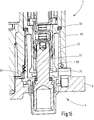
- the Fig. 14 shows a section of a section through a second embodiment of a housing 148 of the first connector part 2. As far as compared to the embodiment of Fig. 8 are designated matching features, reference numerals are used to the Amount 100 compared to in the Fig. 8 used reference numerals are increased.
- a shield member 159 is inserted, as shown in the FIGS. 10 to 13 is shown.
- the shield element 159 comprises a third part 137, with which the cable shield 157 of the line 106 is mechanically fixed, in particular crimped; the third part 137 may also be referred to as Stützcrimp.
- the third part 137 firmly encloses both the cable screen 157 on the insulation 155 and the cable outer jacket of the line 106.
- the portion of the third part 137, which encloses the insulation 155 or the cable shield 157, is axially spaced from the portion of the third part 137, which encloses the outer cable sheath.
- the embodiment of the housing 148 of Fig. 14 is like the embodiment of the Fig. 8 inside conical. Unlike the Fig. 8 is at the housing 148 of the Fig. 14 also the outer shape conical, since the wall thickness is approximately constant.
- the protruding and cut to a suitable length end of the cable shield 157 is folded over and is enclosed by the second part 135 of the shield member 159.
- the second part 135 is shaped such that its outer edge reaches almost to the inner surface of the housing 148.
- this has a stiffening means 139, which is formed in the embodiment by an annular recess.
- the second part 135 has a preferably circumferential and at right angles to the longitudinal axis extending edge portion 141, which is set back in the embodiment of the axial ends of the second part 135, wherein the distance to one axial end is smaller than the opposite other axial end ,
- the second part 185 of the fixing element is supported positively in the axial direction; the second part 185 may also be referred to as a sealing sleeve.
- the first part 181 of the fixing element is positively supported in the axial direction, wherein the support of the first part 181 is radially inward of the support of the second part 185 of the fixing element; the first part 181 may also be referred to as a spacer sleeve.
- the second part 135 is rotationally symmetrical to its longitudinal axis. By turning over the cable shield 157, this has a defined distance from the main contact.
- the first part 131 of the shield member 159 is arranged.
- it consists of a slotted sleeve which, in the undeformed state, has a shape which deviates from the cylindrical shape, in particular is conical.
- the first part 131 on its outer surface preferably integrally formed by embossing and circumferentially preferably uniformly distributed contact tongues 161 or contact tabs, with which the housing 148 is electrically contacted.
- the first part 131 on its inside preferably integrally formed by embossing and circumferentially preferably uniformly distributed second contact tongues 143 or contact lugs with which the second part 135 of the shield member 159 is electrically contacted.
- the first part 131 is brought approximately in a cylindrical shape, since during assembly, the cable of the line 106 with the parts mounted thereon in the housing 148 is inserted. By the restoring force of the first part 131 this is in safe electrical contact on the one hand on the inner surface of the housing 148 and on the other hand on the second part 135 of the shield member 159.
- integrally formed stop means for abutment on the second part 135 are arranged in particular for bearing on the edge portion 141 of the second part 135, by which it is ensured that the first part 131 is axially in a defined position in the housing 148, in particular in a defined position relative to the second part 135 and thus with respect to the line 106
- the stop means may be formed by the second contact tongues 143.
- a defined contact of the first part 131 is ensured both radially outward on the housing 148 and radially inward.
- a radially inner second contact tongue 143 is arranged, wherein the connecting line between mutually associated contact tongues 161, 143 extends parallel to the longitudinal axis of the line 106 in order to ensure a corresponding current flow direction for the cable shield current. Due to the small distance of the sleeve-shaped first part 131 from the housing 148, a good capacitive coupling of the shield contact is ensured.
- the outer diameter of the second part 135 in the region of the edge portion 141 is only slightly smaller than the clear width of the housing 148 minus the thickness of the first part 131, so that in this area a clearance of less than 2 mm, in particular less than 1.2 mm and preferably less than 0.8 mm; in the embodiment, the distance is about 0.5 mm.
- a Radial movement of the line 106, in particular of the cable with the parts mounted thereon, ie also with the second part 135, moves the first part 131 at that axial position at which the first part 131 electrically contacts the second part 135, likewise the movement through the abutment of the first part 131 on the inside of the housing 148 experiences a stop.
- the first part 131 does not undergo any movement in the radial direction, because the first part 131 is centered by the abutment of the contact tongues 161 within the housing 148. This results in a pivoting movement of the first part 131, which has the advantage that thereby takes place a relative movement at the contact points, thereby cleaning the contact surfaces.
- the end portion of the first part 131, with which the first part 131 is in communication with the second part 135, is at an angle of more than 0.2 ° and less than 6 °, in particular more than 0.5 °, with respect to the adjacent part and bent less than 4 ° and preferably more than 0.5 ° and less than 2.5 ° inward so that this end portion undergoes no bending stress in a pivoting movement of the first part 131, which would be detrimental to the occurrence of vibration.
- the length of the bent portion is less than 30% of the length of the first part 131, in particular less than 20% and preferably less than 15%. In the exemplary embodiment, the length of the bent portion is up to +/- 25% equal to the length of the second contact tongues 143.
- the Fig. 15 shows a perspective view of a section of the second connector part 4 in the region of the pilot contact 18.
- An electrically conductive, loosely applied sleeve-shaped portion 64 on the plug-in unit for the pilot contact 18 has at its the terminal block 30th facing the end of a flange-like widening 66, on which one of the terminal block 30 preferably integrally formed contact nose 65 can be brought into abutting contact, wherein the contact nose 65 resiliently relative to the terminal block 30 can be deflected and fixed the sleeve-shaped portion 64 to the housing wall 8 and the Screen connection ensures.
- the contact tabs 65 are down holders for the conductive and end-bent sleeve with flange-like widening 66, which places the shield connection on the potential of the unit.
- the Fig. 16 shows a section of a section through the housing 48 of the first connector part 2 and the housing wall 8 of the unit with the second connector element 4 in the assembled state.
- a seal 69 is arranged, in particular in contact with the annular portion 38 (FIGS. Fig. 1 ) of the sleeve-shaped portion 32 on the one hand and the housing 48 on the other.
- the guide section 75 of the first plug connection element 2 projects in the direction of the second plug connection element 4 beyond the contact elements of the first plug connection element 2, so that these are disposed in the first plug connection element 2 in a touch-proof manner.
- One of the terminal block 30 preferably integrally formed dome 67 is in contact-bearing contact with the housing 48 of the first connector element 2.
- the terminal block 30 in the region of the passage of the load contacts 12, 14, 16 thereby form-locking counter-holding the housing 48th
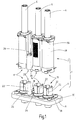
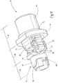
- the Fig. 17 shows a perspective view of a first embodiment of a connector element 10 for use in the above-described first connector part 2.
- the connector element 10 has two formed by shaped electrically conductive sheet metal strips contact plates 72, 74, each having a connection portion 76, which in the illustration of Fig. 17 is concealed by the sleeve-shaped connecting element 78, for the electrical connection of the connector element 10 to the electrical line 6.
- the contact plates 72, 74 a contact portion 82, for a releasable electrical connection of the connector element 10 with a contact member of the second connector element 4.
- the contact plates 72, 74 have a compensation section 80 arranged between the connection section 76 and the contact section 82 for elastic deflection of the contact section 82 relative to the connection section 76.
- the two contact plates 72, 74 are bent partially circular, in particular each approximately semicircular, and are fixed by the sleeve 78 in the position shown.
- the connecting element 78 has, at its end facing the contact section 82, a support element 84 formed by a flange-like widening, by means of which the connecting element 78 can be supported on a counter element.
- the connecting element and thus the line 6 can be fixed in the housing 48 of the first connector element 2 when a tensile force occurs by positive engagement. Tensile forces or, for example, vibrations are thereby not forwarded to the contact section 82, as a result of which the electrical connection is particularly reliable.
- connection section 76 to be connected line 6 is permanently connected by crimping the sleeve 78, in particular by the molding of a hexagon, securely connected to the connector element 10.
- the support member 84 causes the forces and / or deformations occurring during crimping to be kept away from the compensating section 80.
- the support element 84 is preceded by a first spreading portion 73, so that the connecting element 78 has a two- or multi-stage widening.
- the two contact plates 72, 74 are each meandering bent, starting first from the terminal portion 76, the first contact plate 72 forms a U-shaped loop and in the axial direction then the second contact plate 74 is a substantially equal sized U-shaped loop forms. Subsequently, the two contact plates 72, 74 extend further into the contact section 82. At the bending points of the meander-shaped loops, the two contact plates 72, 74 each have at least one recess 86, through which the strip width of the contact plate 72, 74 is reduced and thereby the flexural rigidity is reduced.
- the two contact plates 72, 74 tool engagement surfaces 90 which are formed in the embodiment by holes, by means of which the contact plates 72, 74 can be fixed during bending of the loops; alternatively or additionally, the holes may also be provided to reduce the flexural rigidity.
- the contact plates 72, 74 in the region of the parallel legs 88 stop means 92 which in Embodiment formed by the contact plates 72, 74 integrally formed and bent by 90 ° lugs.
- the two contact plates 72, 74 are bent in a V-shape and enclose an angle between 60 and 150 °, preferably between 75 and 120 °.
- the contact plates 72, 74 have a bending shape which deviates from the cross-sectional contour of the contact element of the second plug connection part 4, resulting in one or preferably two line contacts per contact plate 72, 74.
- a foreign spring 94 is placed, with the contact plates 72, 74 in contact-bearing contact with the contact member of the associated second connector part 4 are preserved.
- the foreign spring 94 has an annular portion 96, which limits the maximum expansion of the contact plates 72, 74 in the contact portion 82.
- the annular portion 96 are in the axial direction spring arms 98 from which are bent or bent in the undeformed initial state inwardly and apply the contact force.
- two spring arms 98 are arranged on opposite sides.
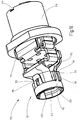
- the Fig. 18 shows a perspective view of a second embodiment of a connector element 110 for use in the first connector part described above 2.
- the first and second contact plates 172, 174 outwardly projecting lugs 111, 113, which together a guide and a stop for form the attachment of the foreign spring 194.
- the annular portion 115 of the foreign spring 194 is disposed on a second plug connection part 4 facing the end. From the annular portion 115 are on opposite sides guide means 117 out, which are introduced when attaching the foreign spring 194 between the two lugs 111, 113.
- the guide means 117 have a rounded or bevelled end portion.
- the guide means 117 alternatively or additionally form spacers which prevent excessive compression of the two contact plates 172, 174.
- the annular portion 115 are on opposite sides locking means 119, which cooperate with corresponding locking means 121 of the contact plates 172, 174.
- the latching means 119 of the foreign spring 194 have an opening or depression, into which engage the locking means 121, for example, a knob, formed integrally, for example by embossing of the contact plates 172, 174 integrally.
- the annular portion 115 terminates at the end substantially flush with the contact plates 172, 174 from.
- the contact plates 172, 174 form at the end an insertion bevel 125 for the contact pin 22 (FIG. Fig. 1 ).
- Each of the contact sheets 172, 174 has two by its shape Line contacts 123 for the contact-making system on the contact pin 22.
- the connecting element 178 has, in the region of the connection section, in particular at its connection section-side end, an adjusting means 127, by means of which the position of the connection element with respect to the contact plates 172, 174 is adjustable.
- the adjusting means 127 may be formed by a recess, in which immediately after the insertion of the contact plates 172, 174 a corresponding position fixing is impressed, so that the connecting element 178 is held only in a predetermined angular position on the contact plates 172, 174 and in the further assembly a twist protection is guaranteed.
- the Fig. 19 shows an embodiment of a connector element 210 for an angle plug.
- one of the contact plates 274 is only cranked and does not form a complete meander loop.
- the insertion of a contact pin 22 takes place transversely to the longitudinal direction of the plug connection element 210 determined by the succession of connection section 276, compensation section 280 and contact section 282.
- the foreign spring 294 is produced as a stamped / bent part and placed on the contact section 282.
- the Fig. 20 shows a further embodiment of a connector element 310 for an angle plug.
- the foreign spring 394 has two legs, each with at least one latching means 319, which cooperate with corresponding latching means 321 of the contact plates 372, 374.
- the locking means 319 of the Foreign spring 394 an opening or depression, in which engage integrally formed, for example, by embossing of the contact plates 372, 374 locking means 321 latching.
- the contact plates 372, 374 form at the end an insertion bevel 325 for the contact pin 22 of the second connector part 4.
- Each of the contact plates 372, 374 has by its shape two line contacts 323 for the contact-bearing system on the contact pin 22.
- At least one of the contact plates 372, 374 has a preferably integrally formed stop means 329, by means of which the contact plates 372, 374 are insertable only up to a corresponding stop in the connecting element 378; the corresponding stop can be formed by the transition from the support element 384 to the first widened portion 373 on the inside of the connecting element 378.
- a secure electrical connection is provided by the provision of a total of four line-shaped electrical contacts.
- the compensating section 80, 280 ensures a secure contact of the contact section 82, 282 with all four contact lines, in particular a compensation of a parallel offset or an inclined position of the contact member to be contacted is ensured.
- the high current carrying capacity is due to the direct contact of a large cross-sectional area having contact plates 72, 74 on the Contact pin 22 provided; the required flexibility of the contact sheets 72, 74 is provided by the balancing section 80, 280, which is formed separately from the contact point and the connection with the line 6.
Landscapes
- Details Of Connecting Devices For Male And Female Coupling (AREA)
- Coupling Device And Connection With Printed Circuit (AREA)
Description
- Die Erfindung betrifft ein elektrisches Steckverbindungselement sowie ein Steckverbindungsteil mit mehreren derartigen Steckverbindungselementen.
- Üblicherweise wird bei elektrischen Steckverbindern ein Steckerelement und ein Buchsenelement zusammengesteckt, wobei die Kontaktorgane des Steckerelements und des Buchsenelements in elektrischen Kontakt miteinander kommen und über die so hergestellten Kontaktflächen der elektrische Strom geführt wird. Bekannte Steckverbinder sehen geschlitzte Kontakte vor, bei denen durch einen Schlitz zwei Kontaktflächen zwischen Stift und Buchse gebildet sind. Bekannt ist auch die Ausführung mit zwei Schlitzen, durch die vier Kontaktflächen gebildet sind. Eine höhere Anzahl von Kontaktflächen ergibt sich durch die Verwendung von sogenannten Lamellenkontakten. Dabei werden beispielsweise gestanzte Lamellen in einem Kontaktträger montiert. Durch die große Anzahl der Kontaktflächen ergibt sich eine hohe Kontaktsicherheit.
- Aus der
DE 10 2007 042 194 A1 ist ein Steckverbindungselement mit einem Kontaktorgan bekannt, das mindestens einen Linienkontakt aufweist, mittels dem das Kontaktorgan beim Zusammenstecken mit einem zugeordneten Verbindungselement elektrisch verbindbar ist. Die damit erreichbaren Kontakt- und Stromtrageigenschaften sind bereits sehr gut. - Aus der
US 2009/0088028 A1 ist ein Steckverbindungselement mit den Merkmalen des Oberbegriffs des Anspruchs 1 bekannt. - Der Erfindung liegt die Aufgabe zugrunde, ein Steckverbindungselement und ein Steckverbindungsteil mit mehreren derartigen Steckverbindungselementen bereitzustellen, die gegenüber den bekannten Steckverbindungselementen bzw. Steckverbindungsteilen noch weiter verbesserte Gebrauchseigenschaften aufweisen. In einer Ausführungsart soll eine hohe Kontaktsicherheit und hohe Stromtragfähigkeit bei einfacher Steckbarkeit gewährleistet sein, insbesondere soll das Steckverbindungselement und das Steckverbindungsteil unempfindlich gegenüber mechanische und/oder thermische Belastungen sein.
- Diese Aufgabe ist durch das im Anspruch 1 bestimmte Steckverbindungselement und das im nebengeordneten Anspruch bestimmte Steckverbindungsteil gelöst. Besondere Ausführungsarten der Erfindung sind in den Unteransprüchen bestimmt.
- In einer Ausführungsart weist das Steckverbindungselement mindestens zwei durch geformte elektrisch leitfähige Blechstreifen gebildete Kontaktbleche auf, die jeweils einen Anschlussabschnitt für den elektrischen Anschluss des Steckverbindungselements an eine anzuschließende elektrische Leitung aufweisen sowie einen Kontaktabschnitt für ein lösbares elektrisches Verbinden des Steckverbindungselements mit einem zugeordneten Verbindungselement und einen zwischen dem Anschlussabschnitt und dem Kontaktabschnitt angeordneten Ausgleichsabschnitt für eine elastische Auslenkung des Kontaktabschnitts gegenüber dem Anschlussabschnitt, wobei der Anschlussabschnitt, der Ausgleichsabschnitt und der Kontaktabschnitt jeweils einstückig von den Blechstreifen ausgebildet sind.
- Die durch den Ausgleichsabschnitt bereitgestellte elastische Auslenkung ist im zusammengesteckten Zustand der beiden Steckverbindungsteile vorteilhaft, weil dadurch Abweichungen in der Lage der Kontaktstifte im montierten Stecksystem aufgefangen werden und nicht zu einer verminderten Kontaktgabe und damit zu einer verminderten Stromtragfähigkeit führen. Auftretende Vibrationen können durch die nachstehend beschriebende Zugentlastung aufgefangen werden. Durch die vorgesehenen Einführschrägen und/oder Kontaktoberflächen und/oder die Überfeder sind die zum Stecken und Lösen erforderlichen Kräfte einstellbar.
- In einer Ausführungsart sind die drei Abschnitte in einer Längsrichtung des Steckverbindungselements hintereinander angeordnet und können die ihnen jeweils zugeordnete Funktion bereitstellen ohne sich gegenseitig negativ zu beeinflussen. Alle drei Abschnitte sind einstückig von jeweils einem oder mehreren Kontaktblechen ausgebildet, so dass Kontaktstellen beispielsweise zwischen dem Anschlussabschnitt und dem Kontaktabschnitt vermieden sind.
- Die Kontaktbleche bilden das Kontaktorgan des Steckverbinderelements. Durch den Ausgleichsabschnitt weisen die Kontaktbleche trotz einer vergleichsweise großen Querschnittsfläche, die eine hohe Stromtragfähigkeit bietet, eine ausreichende Flexibilität auf. Daher können die Kontaktbleche unmittelbar, d.h. ohne Zwischenlage eines kontaktgebenden Organs, in Anlage an das Kontaktorgan des zugeordneten Steckverbindungsteils gebracht werden. Es entfällt damit eine im Stand der Technik bei hohe Stromtragfähigkeit erforderliche zusätzlich Kontaktstelle am Übergang des Kontaktorgans zu einem weiterführenden Abschnitts innerhalb des Steckverbindungselements. Das erfindungsgemäße Steckverbindungselement weist daher nicht nur eine hohe Stromtragfähigkeit auf, sondern besitzt auch eine verbesserte Vibrationsfestigkeit.
- Der Werkstoff für die Kontaktbleche ist vorzugsweise reines Kupfer, um den Gesamtwiderstand des Steckverbindungselements zu minimieren. Vorzugsweise wird als Werkstoff sauerstoffarmes oder sauerstofffreies Kupfer verwendet. Dadurch lässt sich auch bei höheren Temperaturen, wie sie beispielsweise beim Einsatz erfindungsgemäßer Steckverbindungselemente in der Kraftfahrzeugtechnik, insbesondere bei wasserstoffbetriebenen Fahrzeugen, einstellen können, eine Versprödung der Kontaktbleche verhindern. Der Kontaktabschnitt oder vorzugsweise das gesamte Kontaktblech kann eine Oberflächenbeschichtung beispielsweise aus Silber oder einem anderen Edelmetall aufweisen, um die Übergangswiderstände auch bei hohen Steckzyklen zu reduzieren.
- Die Kontaktbleche sind im Anschlussabschnitt von einem mindestens abschnittsweise hülsenförmigen Verbindungselement umschlossen, mittels dem in einem Ausgangszustand die Kontaktbleche in ihrer Position zueinander fixiert sind. Die Kontaktbleche können hierzu im Anschlussabschnitt teilkreisförmig, insbesondere annähernd halbkreisförmig bei der Verwendung von zwei Kontaktblechen, gebogen sein, so dass sich allein durch das Einstecken des Anschlussabschnitts der beiden Kontaktbleche in das Verbindungselement eine Fixierung der Kontaktbleche ergibt.
- Beim Anschließen der elektrischen Leitung wird mittels des Verbindungselements eine Crimpverbindung der Kontaktbleche mit der elektrischen Leitung hergestellt. Durch die Verwendung einer Hülse wird eine dauerhafte und alterungsbeständige Kontaktierung gewährleistet. An ihrem der anzuschließenden elektrischen Leitung zugewandten Ende weist das Verbindungselement vorzugsweise eine Einführschräge auf. Das Verbindungselement besteht vorzugsweise ebenfalls aus vergleichsweise weichem Kupfer. Vorzugsweise wird eine Sechskantverpressung vorgenommen, um die Kontakteigenschaften zu verbessern und eine dauerhaft sichere mechanische Verbindung zwischen dem Steckverbindungselement und der elektrischen Leitung bereitzustellen.
- In einer Ausführungsart erstreckt sich die Hülse über den Crimpbereich hinaus. Dadurch wirkt sich die Verformung der Kontaktbleche im Anschlussabschnitt nicht auf den sich anschließenden Ausgleichsabschnitt aus. Um diese mechanische Abschirmwirkung noch weiter zu verbessern, weist das Verbindungselement in einer Ausführungsart ein Stützelement auf, beispielsweise einen ein- oder mehrstufigen, insbesondere zweistufigen, ringförmigen Flansch, mit dem das Verbindungselement alternativ oder ergänzend auch an einem Gehäuse des zugehörigen Steckverbindungsteils abstützbar ist. Dadurch werden Bewegungen und/oder Vibrationen der angeschlossenen Leitung, bei der es sich beispielsweise um ein Kabel handeln kann, von dem zugeordneten Verbindungselement aufgenommen und nicht in den Kontaktabschnitt übertragen.
- In einer Ausführungsart weist mindestens eines der Kontaktbleche im Ausgleichsabschnitt eine herabgesetzte Biegesteifigkeit auf. Dies kann beispielsweise durch eine oder mehrere Aussparungen in der Wandstärke und/oder durch einen oder mehrere laterale Einschnitte in die Streifenbreite der Kontaktbleche bereitgestellt werden. Dadurch wird eine Soll-Gelenkstelle geschaffen, die eine Auslenkung des Kontaktabschnitts gegenüber dem Anschlussabschnitt mit einer vergleichsweise geringen Kraft ermöglicht. Dadurch sind in besonders vorteilhafter Weise geringe Steckkräfte realisierbar und/oder vorallem ein Ausgleich temperaturbedingter Ausdehnungszustände der zusammenwirkenden Bauteile, die aus unterschiedlichen Werkstoffen bestehen. Weil das Kontaktblech im Crimpbereich fixiert ist, kann durch den Ausgleichsbereich auch eine Elastizität des Steckverbindungselements bereitgestellt werden, die trotz fertigungsbedingten Toleranzen eine optimale Kontaktgabe im Kontaktabschnitt gewährleistet.
- In einer Ausführungsart ist mindestens ein Kontaktblech, vorzugsweise alle und insbesondere beide Kontaktbleche, des Steckverbindungselements im Ausgleichsabschnitt mäanderförmig gebogen oder jedenfalls gekröpft. Dadurch können im Kontaktabschnitt die Kontaktbleche mit verhältnismäßig geringem Kraftaufwand derart ausgelenkt werden, dass ein Zusammenstecken des Steckverbindungselements mit einem zugeordneten Verbindungselement und das Lösen einer solchen Steckverbindung mit geringem Kraftaufwand möglich sind. Im mäanderförmigen Ausgleichsabschnitt weisen die beiden abschnittsweise parallel verlaufenden Schenkel einen Abstand zueinander auf. Dadurch ist ein Bewegungsspiel beim Auslenken gewährleistet. An den Biegestellen des Ausgleichsabschnitts kann die Steifigkeit des Kontaktblechs herabgesetzt sein, beispielsweise durch eine Materialaussparung, und insbesondere durch eine lokale Reduktion der Breite des Kontaktblechs.
- In einer Ausführungsart weist mindestens ein Kontaktblech im Ausgleichsabschnitt ein vorzugsweise einstückig ausgebildetes Anschlagmittel auf, um die Auslenkung des Kontaktabschnitts gegenüber dem Anschlussabschnitt zu begrenzen. Beispielsweise kann an mindestens einem der im Mäanderbereich parallel verlaufenden Schenkel des Kontaktblechs ein seitlicher Fortsatz in Richtung auf den gegenüberliegenden Schenkel abgebogen sein. Bei einer maximalen Auslenkung kommt der abgebogene Abschnitt in Anlage an den gegenüberliegenden Schenkel, wodurch die Auslenkung begrenzt ist.
- In einer Ausführungsart weist mindestens ein Kontaktblech im Kontaktabschnitt eine Querschnittsform auf, die von der Querschnittsform eines Kontaktorgans des zugeordneten Verbindungselements abweicht; dadurch sind beim Zusammenstecken mit dem zugeordneten Verbindungselement zwei elektrische Linienkontakte gebildet. In einer Ausführungsart ist mindestens ein Kontaktblech des Kontaktabschnitts V-förmig oder U-förmig gebogen. Beim Zusammenstecken des Steckverbindungselements mit dem zugeordneten Verbindungselement werden dadurch von jedem Kontaktblech zwei elektrische Linienkontakte gebildet. In einer Ausführungsart, in der das Steckverbindungselement zwei Kontaktbleche aufweist, werden dadurch insgesamt vier elektrische Linienkontakte gebildet. Die Länge der Linienkontakte wird begrenzt durch die Länge der V-förmig oder U-förmig gebogenen Kontaktbleche im Kontaktabschnitt. In einer Ausführungsart beträgt diese Länge zwischen 2 und 20 mm, insbesondere zwischen 4 und 15 mm und vorzugsweise zwischen 6 und 10 mm. Dadurch lässt sich beispielsweise eine Kurzschlussstrombelastbarkeit von 3.000 A für die Dauer von 1 s bereitstellen.
- In einer Ausführungsart bilden die Kontaktbleche im Kontaktabschnitt eine Steckaufnahme für ein beispielsweise stiftförmiges Kontaktorgan des zugeordneten Verbindungselements. Die Längsachse der Steckaufnahme und damit die Steckrichtung kann dabei längs oder schräg und insbesondere quer zur Längsrichtung des Steckverbindungselements, in welcher der Kontaktabschnitt, der Ausgleichsabschnitt und der Anschlussabschnitt hintereinander angeordnet sind, ausgerichtet sein.
- In einer Ausführungsart ist im Kontaktabschnitt eine Fremdfeder angeordnet, mit der die Kontaktbleche in kontaktgebende Anlage an dem zugeordneten Verbindungselement haltbar sind. Die Fremdfeder kann aus einem Federstahl mit geeigneten elastischen Werkstoffen hergestellt sein, insbesondere sind keine besonderen elektrischen Eigenschaften erforderlich. Vorzugsweise ist die Fremdfeder aus einem nicht magnetisierbaren Werkstoff hergestellt. Die Fremdfeder liegt außerhalb des Strompfades, so dass ein elektrischer Kontakt nur zwischen dem Kontaktabschnitt des Kontaktblechs und dem Kontaktorgan des zugeordneten Verbindungselements erfolgt.
- In einer Ausführungsart weist die Fremdfeder einen ringförmigen Abschnitt auf, der die maximale Aufweitung der Kontaktbleche im Kontaktabschnitt begrenzt. Von dem ringförmigen Abschnitt können Federarme abstehen, insbesondere in Richtung auf das dem zugeordneten Verbindungselement zugewandte Ende des Kontaktblechs, welche die erforderliche Kontaktkraft aufbringen. Die Federarme können dabei nach radial innen gebogen sein, um in Anlage an den Kontaktblechen gehalten zu sein. Die Anzahl der Federarme kann dabei übereinstimmen mit der Anzahl der Kontaktbleche oder ein Vielfaches der Anzahl der Kontaktbleche betragen.
- In einer Ausführungsart weist die Fremdfeder Führungsmittel auf, mittels denen die Fremdfeder in einer sich in Steckrichtung erstreckenden Aussparung zwischen den Kontaktblechen geführt auf die Kontaktbleche aufsteckbar ist. Die Führungsmittel können dabei auch in Steckrichtung von dem ringförmigen Abschnitt der Fremdfeder abstehen und nach radial innen abgebogen sein.
- In einer Ausführungsart weist ein Kontaktblech ein vorzugsweise am Übergang vom Kontaktabschnitt zum Ausgleichsabschnitt angeordnetes Anschlagmittel für die Fremdfeder auf. Das Anschlagmittel kann insbesondere am Übergang von dem V-förmig oder U-förmig geformten Kontaktabschnitt zu dem Mäander des Ausgleichsabschnitts angeordnet sein. Durch das Anschlagmittel ist ein Tiefenanschlag beim Aufschieben der Fremdfeder bereitgestellt.
- Die Erfindung betrifft auch ein Steckverbindungsteil mit mehreren erfindungsgemäßen Steckverbindungselementen wie vorstehend beschrieben, wobei die Steckverbindungselemente als Gleichteile in einem gemeinsamen Gehäuse des Steckverbindungsteils angeordnet sind. Dadurch lassen sich mehrpolige Steckverbindungsteile in der Art eines Baukastensystems mit erfindungsgemäßen Steckverbindungselementen bestücken. Die einzelnen Steckverbindungselemente eines Steckverbindungsteils können dabei vollständig identisch aufgebaut sein und auch identische Abmessungen aufweisen. Alternativ hierzu kann das Steckverbindungsteil auch unterschiedlich dimensionierte Steckverbindungselemente aufnehmen, beispielsweise für unterschiedlich hohe Lastströme.
- Das erfindungsgemäße Steckverbindungselement kann für unterschiedlich hohe Nennströme skaliert werden. So kann beispielsweise für einen Nennstrom von 100 A das Kontaktblech bei einer Breite von 8 mm eine Dicke von 0,8 mm aufweisen, und im Anschlussabschnitt können Leitungen oder Kabel mit einer Querschnittsfläche von 16 bis 25 mm2 angeschlossen werden. Bei einem Nennstrom von 200 A kann das Kontaktblech bei einer Breite von 12 mm eine Dicke von 1,0 mm aufweisen, und im Anschlussabschnitt können Leitungen oder Kabel mit einer Querschnittsfläche von 35 bis 50 mm2 angeschlossen werden.
Bei einem Nennstrom von 400 A kann das Kontaktblech bei einer Breite von 16 mm eine Dicke von 1,25 mm aufweisen, und im Anschlussabschnitt können Leitungen oder Kabel mit einer Querschnittsfläche von 70 bis 95 mm2 angeschlossen werden. - In einer Ausführungsart sind die Steckverbindungselemente für elektrische Spannungen im Bereich von mehr als 12 V und weniger als 2400 V ausgelegt, insbesondere mehr als 24 V und weniger als 1000 V und vorzugsweise bis zu einer Betriebsspannung von 700 V. In einer Ausführungsart werden die Steckverbindungsteile in der Fahrzeugtechnik eingesetzt, insbesondere bei Elektro- oder Hybridfahrzeugen oder elektrischen Kraftmaschinen.
- Weitere Vorteile, Merkmale und Einzelheiten der Erfindung ergeben sich aus den Unteransprüchen und der nachfolgenden Beschreibung, in der unter Bezugnahme auf die Zeichnungen mehrere Ausführungsbeispiele im Einzelnen beschrieben sind. Dabei können die in den Ansprüchen und in der Beschreibung erwähnten Merkmale jeweils einzeln für sich oder in beliebiger Kombination erfindungswesentlich sein.
- Fig. 1
- zeigt eine perspektivische Ansicht eines ersten Ausführungsbeispiels eines Steckverbindungssystems,
- Fig. 2
- zeigt eine perspektivische Ansicht eines zweiten Ausführungsbeispiels eines Steckverbindungssystems,
- Fig. 3
- zeigt eine perspektivische Ansicht eines dritten Ausführungsbeispiels eines Steckverbindungssystems,
- Fig. 4
- zeigt eine Seitenansicht des Steckverbindungssystems der
Fig. 3 , - Fig. 5
- zeigt eine perspektivische Ansicht des Steckverbindungssystems in einem teilweise getrennten Zustand,
- Fig. 6
- zeigt in perspektivischer Ansicht einen vergrößerten Ausschnitt im Bereich der Rastmittel,
- Fig. 7
- zeigt einen vergrößerten Ausschnitt im Bereich der Rastelemente,
- Fig. 8
- zeigt einen Ausschnitt eines Schnitts durch das Gehäuse des ersten Steckverbindungsteils,
- Fig. 9
- zeigt eine perspektivische Ansicht eines Abschnitts der Leitung mit der am Leiterende abgesetzten Isolation,
- Fig. 10
- zeigt eine perspektivische Ansicht eines Abschnitts der Leitung mit einer alternativen Ausführungsform eines Schirmelements,
- Fig. 11
- zeigt eine Ansicht von oben auf das erste Teil des Schirmelements,
- Fig. 12
- zeigt eine Seitenansicht auf einen Schnitt durch das erste Teil des Schirmelements,
- Fig. 13
- zeigt einen Schnitt durch ein zweites Teil des Schirmelements,
- Fig. 14
- zeigt einen Ausschnitt eines Schnitts durch ein zweites Ausführungsbeispiel eines Gehäuses des ersten Steckverbindungsteils,
- Fig. 15
- zeigt eine perspektivische Ansicht eines Ausschnitts des zweiten Steckverbindungsteils im Bereich des Pilotkontakts,
- Fig. 16
- zeigt einen Ausschnitt eines Schnitts durch das Gehäuse des ersten Steckverbindungsteils,
- Fig. 17
- zeigt eine perspektivische Ansicht eines ersten Ausführungsbeispiels eines Steckverbindungselements,
- Fig. 18
- zeigt eine perspektivische Ansicht eines zweiten Ausführungsbeispiels eines Steckverbindungselements,
- Fig. 19
- zeigt ein Ausführungsbeispiel eines Steckverbindungselements für einen Winkelstecker, und
- Fig. 20
- zeigt ein weiteres Ausführungsbeispiel eines Steckverbindungselements für einen Winkelstecker.
- Die
Fig. 1 zeigt eine perspektivische Ansicht eines ersten Ausführungsbeispiels eines Steckverbindungssystems 1 mit einem ersten Steckverbindungsteil 2 und einem zweiten Steckverbindungsteil 4 im noch nicht zusammengesteckten Zustand. Das erste Steckverbindungsteil 2 ist als dreipoliger Stecker ausgebildet, mit dem drei jeweils einpolige elektrische Leitungen 6, die jeweils als Kabel mit einem Kabelmantel ausgebildet sind, elektrisch mit dem zweiten Steckverbindungsteil 4 verbindbar sind. Hierzu sind in einem Gehäuse 48 beispielsweise die in denFig. 17 und18 dargestellten buchsenförmigen Kontaktorgane angeordnet, die beim Zusammenstecken des ersten und zweiten Steckverbindungsteils 2, 4 mit vorzugsweise zylindrischen Kontaktstiften 22 im zweiten Steckverbindungsteil 4 in elektrischen Kontakt bringbar sind. - Das zweite Steckverbindungsteil 4 ist im Ausführungsbeispiel an einer Gehäusewand 8 eines Aggregats angeordnet, beispielsweise an einer Lichtmaschine oder an einem Elektromotor. Das erste und zweite Steckverbindungsteil 2, 4 weisen jeweils drei Lastkontakte 12, 14, 16 auf, die einer elektrischen Verbindung der elektrischen Leitungen 6 dienen, und einen Pilotkontakt 18 von dem in der
Fig. 1 nur der zugehörige Pilotkontakt des zweiten Steckverbindungsteils 4 teilweise sichtbar ist. - Die beiden Steckverbindungsteile 2, 4 weisen außerdem Komponenten 20 für eine Führung des ersten Steckverbindungsteils 2 beim Zusammenstecken mit dem zweiten Steckverbindungsteil 4 auf, wobei auf Seiten des zweiten Steckverbindungsteils 4 als Führungskomponente ein mindestens abschnittsweise zylindrischer Zapfen 24 angeordnet ist, der an seinem dem ersten Steckverbindungsteil 2 zugewandten Ende verjüngt ist, insbesondere abgerundet ist und/oder eine Kegelfläche aufweist.
- Zwischen den Komponenten 20 für die Führung und dem Pilotkontakt 18 weisen die beiden Steckverbindungsteile 2, 4 Komponenten für eine Verriegelung des ersten Steckverbindungsteils 2 am zweiten Steckverbindungsteil 4 auf, die im Ausführungsbeispiel auf der Seite des ersten Steckverbindungsteils 2 eine Verbindungsschraube 26 aufweist und auf Seiten des zweiten Steckverbindungsteils 4 eine Gewindebohrung 28. Das zweite Steckverbindungsteil 4 ist mittels einer Anschlussleiste 30 an der Gehäusewand 8 vorzugsweise lösbar festlegbar, im Ausführungsbeispiel angeschraubt.
- Im ersten Ausführungsbeispiel der
Fig. 1 weist das erste Steckverbindungsteil 2 eine parallel zur Steckrichtung verlaufende Leitungsführung auf. DieFig. 2 zeigt ein zweites Ausführungsbeispiel eines Steckverbindungssystems 1, bei dem das erste Steckverbindungsteil 102 eine abgewinkelt zur Steckrichtung verlaufende Leitungsführung der elektrischen Leitungen 6 aufweist, insbesondere eine um 90° abgewinkelte Leitungsführung. Das zweite Steckverbindungsteil 4 ist dabei identisch zu dem zweiten Steckverbindungsteil 4 des ersten Ausführungsbeispiels derFig. 1 aufgebaut, insbesondere ist sowohl ein erstes Steckverbindungsteil 2 mit parallel zur Steckrichtung verlaufender Leitungsführung, wie in derFig. 1 dargestellt, als auch ein erstes Steckverbindungsteil 102 mit abgewinkelt zur Steckrichtung verlaufender Leitungsführung mit demselben zweiten Steckverbindungsteil 4 zusammensteckbar. - Die Komponenten einer ersten Komponentengruppe mit Komponenten für den Pilotkontakt 18, und die Komponenten für die drei Lastkontakte 12, 14, 16 sind unabhängig von einer durch die Anzahl der Lastkontakte 12, 14, 16 bestimmten Polzahl des ersten Steckverbindungsteils 102, insbesondere ist der Pilotkontakt 18 stets identisch ausgebildet, unabhängig davon, ob es sich um eine ein-, zwei- oder n-polige Steckverbindung handelt; entsprechendes gilt für die Lastkontakte 12, 14, 16 in der geraden Ausführung und die Lastkontakte 212, 214 in der gewinkelten Ausführung (
Fig. 3 ). Auch die Komponenten 20 für eine Führung beim Zusammenstecken und die Komponenten 26 für die Festlegung des ersten Steckverbindungsteils 2 an dem zweiten Steckverbindungsteil 4 sind unabhängig von der Anzahl der Pole ausgebildet. - Das Gehäuse 48 des ersten Steckverbindungsteils 2 weist eine der durch die Anzahl der Lastkontakte 12, 14, 16 bestimmten Polzahl entsprechende Anzahl von Aufnahmekammern für die Komponenten der Lastkontakte 12, 14, 16 auf. Die innerhalb des Gehäuses 48 angeordneten Komponenten der Lastkontakte 12, 14, 16 sind identisch aufgebaut. Die Komponenten 20 für die Führung beim Zusammenstecken, sowie die Komponenten des Pilotkontaktes 18 und der Festlegung 26 sind zwischen dem in den
Fig. 1 und2 links angeordneten ersten Lastkontakt 12 und dem mittleren Lastkontakt 14 angeordnet. In einer Ausführungsart ist diese Anordnung auch bei zwei- oder mehrpoligen Steckverbindungen beibehalten, insbesondere ist die Anordnung der Komponenten 20 für die Führung, des Pilotkontaktes 18 und des Verbindungsmittels 26 unabhängig von der Anzahl der Pole des Steckverbindungssystems 1 immer zwischen zwei benachbarten Lastkontakten 12, 14 angeordnet. - Das zweite Steckverbindungsteil 4 weist einen den Kontaktstift 22 in Axialrichtung überragenden hülsenförmigen Abschnitt 32 auf, der einer weiteren Führung des ersten Steckverbindungsteils 2, 102 beim Zusammenstecken mit dem zweiten Steckverbindungsteil 4 dienen kann. Der hülsenförmige Abschnitt 32 weist eine sich in Steckrichtung erstreckende Öffnung 34 auf, die in Richtung des ersten Steckverbindungsteils 2, 102 offen ist und im Ausführungsbeispiel durch einen Schlitz gebildet ist. Im zusammengesteckten Zustand ragt das erste Steckverbindungsteil 2, 102 mit seinem Gehäuse 48 über ein dem zweiten Steckverbindungsteil 4 zugewandtes Ende 36 der Öffnung 34 hinaus. Daran schließt sich ein ringförmiger und vorzugsweise zylindrischer oder kegelförmiger Abschnitt 38 an, an den im zusammengesteckten Zustand ein Dichtmittel in Anlage bringbar ist und dadurch die Kontaktorgane des Steckverbindungssystems 1 abdichtet. Auf seiner Innenseite weist der hülsenförmige Abschnitt 32 vorzugsweise einstückig ausgebildete Führungsmittel 40 auf, die sich im Ausführungsbeispiel in Axialrichtung erstrecken und als Stege ausgebildet sind, und durch die beim Zusammenstecken eine weitere Führung und/oder Verpolungssicherheit gewährleistet ist. In einer Ausführungsart können die Führungsmittel bzw. Stege sowie die zugehörigen Aussparungen eine kundenspezifisch wählbare Codierung des Steckverbindungssystems 1 bilden.
- Die
Fig. 3 zeigt eine perspektivische Ansicht eines dritten Ausführungsbeispiels eines Steckverbindungssystems 201 mit einem zweipoligen ersten Steckverbindungsteil 202 und einem zweipoligen zweiten Steckverbindungsteil 204, wobei es sich bei dem ersten Steckverbindungsteil 202 um einen Winkelstecker handelt, bei dem die Leitungsführung rechtwinklig zur Steckrichtung verläuft. - Die
Fig. 4 zeigt eine Seitenansicht des Steckverbindungssystems 201 derFig. 3 . DieFig. 5 zeigt in einer gegenüber denFig. 3 und 4 vergrößerten Darstellung eine perspektivische Ansicht des Steckverbindungssystems 201 in einem teilweise getrennten Zustand. - Das erste Steckverbindungsteil 202 weist ein bügelförmiges Betätigungselement 242 auf, mit dem die beiden Steckverbindungsteile 202, 204 aus dem in den
Fig. 3 und 4 vollständig zusammengesteckten Zustand in einen in derFig. 5 dargestellten Zustand überführbar sind, in dem der Pilotkontakt 218 entweder bereits getrennt ist, oder jedenfalls bei einer vollständigen Überführung des Betätigungselements 242 in eine gegenüber der Darstellung in denFig. 3 und 4 um 90° gedrehten Position getrennt ist, die Lastkontakte 212, 214 aber noch elektrisch verbunden sind. Das Betätigungselement 242 ist um einen vorzugsweise einstückig von dem ersten Steckverbindungsteil 202 ausgebildeten Achszapfen 244 schwenkbar, woraufhin eine in dem Betätigungselement 242 beispielsweise durch eine Nut eingebrachte Steuerkurve 246 derart entlang einem an dem zweiten Steckverbindungsteil 204 angeordneten Führungszapfen 250 bewegt wird, dass das erste Steckverbindungsteil 202 von dem zweiten Steckverbindungsteil 204 abhebt. - Wenn das Betätigungselement 242 eine gegenüber der Position in der
Fig. 3 um 90° gedrehte Position einnimmt, ist der Pilotkontakt 218 des ersten Steckverbindungselements 202 nicht mehr in elektrischer Verbindung mit dem Pilotkontakt des zweiten Steckverbindungselements 204, wohingegen die Lastkontakte 212, 214 des ersten Steckverbindungselements 202 noch in elektrischer Verbindung mit den Lastkontakten des zweiten Steckverbindungselements 204 sind. - Das Betätigungselement 242 kann in seiner in den
Fig. 3 und 4 dargestellten ersten Endposition und/oder in einer demgegenüber um 90° gedrehten zweiten Endposition lösbar rastbar sein. Durch die Hebelwirkung des Betätigungselements 242 ist sowohl beim Öffnen als auch beim Schließen der Verbindung zwischen dem ersten und dem zweiten Steckverbindungsteil 202, 204 nur eine geringe Betätigungskraft erforderlich. Dies ist insbesondere bei hohen Temperaturen und/oder schmutzenden Umgebungsbedingungen vorteilhaft. - Das erste Steckverbindungsteil 202 und das zweite Steckverbindungsteil 204 weisen miteinander korrespondierende Rastmittel 252, 254 auf, wobei im Ausführungsbeispiel das Rastmittel 252 des ersten Steckverbindungsteils 202 durch eine Aussparung in einer Gehäusewand gebildet ist, in welche das zugehörige Rastmittel 254 des zweiten Steckverbindungsteils 204 beim Aufstecken eingreift und dabei mit der Öffnung verrastet. Hierzu weist das Rastmittel 254 des zweiten Steckverbindungsteils 204 eine Anlaufschräge auf, mittels welcher das Rastmittel 254 beim Zusammenstecken ausgelenkt wird und zurückschnappt, sobald das Rastmittel 254 in die Öffnung im ersten Steckverbindungsteil 202 eingreift.
- Nach einem Überführen des ersten Steckverbindungsteils 202 aus der in den
Fig. 3 und 4 dargestellten Position in die in derFig. 5 dargestellte Position oder darüber hinaus in eine Position, in welcher das Betätigungselement 242 um 90° geschwenkt wurde, ist das Rastmittel 254 des zweiten Steckverbindungsteil 204 in Anlage an dem Rand der das Rastmittel 252 bildenden Öffnung des ersten Steckverbindungsteils 202. Dadurch ist ein vollständiges Abziehen des ersten Steckverbindungsteils 202 verhindert. Erst nachdem, beispielsweise mittels eines Schraubendrehers oder eines sonstigen geeigneten Werkzeugs, das beispielsweise in die Öffnung einführbar und anschließend drehbar ist, das Rastmittel 254 außer Eingriff mit dem Rastmittel 252 gebracht wird, kann das erste Steckverbindungsteil 202 vollständig abgezogen werden. - Dadurch, dass zunächst das Betätigungselement 242 betätigt werden muss, und dadurch der Pilotkontakt 218 getrennt wird, während die Lastkontakte 212, 214 noch in Verbindung sind, und anschließend die Rastmittel 252, 254 beispielsweise mittels eines Werkzeuges, alternativ auch werkzeuglos von Hand, außer Eingriff gebracht werden müssen, bevor das erste Steckverbindungsteil 202 vollständig abgezogen werden kann, ergibt sich in der Praxis eine Zeitverzögerung von beispielsweise mindestens 0,5 oder 1 Sekunde. Dies ermöglicht einer übergeordneten Steuerung die Lastkontakte 212, 214 stromlos zu schalten, nachdem durch das Trennen des Pilotkontaktes 218 signalisiert wird, dass die Verbindung getrennt werden soll.
- Auch beim Zusammenstecken ergibt sich die Möglichkeit, dass zunächst durch das Aufstecken des ersten Steckverbindungsteils 202 eine Verbindung der Lastkontakte 212, 214 hergestellt wird, und erst durch das anschließende Schwenken des Betätigungselements 242 auch der Pilotkontakt 218 geschlossen wird, woraufhin eine übergeordnete Steuerleitung die Lastleitungen unter Strom setzen kann. Somit kann sowohl das Stecken als auch das Lösen der elektrischen Verbindung der Lastkontakte 212, 214 stromlos erfolgen, wodurch die elektrischen Kontakte geschont werden und eine dauerhaft zuverlässige elektrische Verbindung bereitgestellt werden kann.
- Die
Fig. 6 zeigt in perspektivischer Ansicht einen vergrößerten Ausschnitt im Bereich der Rastmittel 252, 254 in einem Zustand, in dem das erste Steckverbindungsteil 202 vollständig mit dem zweiten Steckverbindungsteil 204 zusammengesteckt sind und sowohl die Lastkontakte 212, 214 als auch der Pilotkontakt 218 geschlossen sind. DieFig. 7 zeigt einen vergrößerten Ausschnitt im Bereich der Rastelemente 252, 254 in einem Zustand, in dem das erste Steckverbindungsteil 202 so weit vom zweiten Steckverbindungsteil 204 gelöst ist, dass der Pilotkontakt 218 getrennt ist, die Lastkontakte 212, 214 aber noch verbunden sind. - Das Rastelement 252 des ersten Steckverbindungsteils weist einen ersten Öffnungsabschnitt 256 auf, der geringfügig größer ist als ein erster Abschnitt 258 des zweiten Rastelements 254, aber kleiner als ein zweiter Abschnitt 260 des zweiten Rastelements 254. Dadurch kommt in der in der
Fig. 7 dargestellten Position der zweite Abschnitt 260 in Anlage an das Gehäuse 48 des ersten Steckverbindungsteils 2 und sperrt ein vollständiges Abziehen des ersten Steckverbindungsteils 202 vom zweiten Steckverbindungsteil 204. Erst durch ein Auslenken des zweiten Rastelements 254, beispielsweise mittels eines Werkzeuges, wird der zweite Abschnitt 260 in Deckung mit einem zweiten, gegenüber dem ersten Öffnungsabschnitt größeren zweiten Öffnungsabschnitt 262 des ersten Rastelements 254 gebracht, der geringfügig größer ist als der zweite Abschnitt 260 des zweiten Rastelements 254, so dass das erste Steckverbindungsteils 202 von dem zweiten Steckverbindungsteil 204 abgenommen werden kann. - Die
Fig. 8 zeigt einen Ausschnitt eines Schnitts durch das Gehäuse 48 des ersten Steckverbindungsteils 2 in einem Bereich, in dem die in einer Ansicht dargestellte elektrische Leitung 6 mit dem ersten Steckverbindungsteil 2 verbunden ist. Bei der Leitung 6 handelt es sich um ein Kabel mit einem Innenleiter 53, der von einer Isolation 55 umgeben ist, auf die außen ein metallisch leitfähiger Kabelschirm 57 aufgebracht ist. An seinem durch ein hülsenförmiges Verbindungselement 78 verdeckten Ende ist der Innenleiter 53 mit einem nachstehend noch beschriebenen elektrischen Steckverbindungselement 10 (Fig. 17 ,18 ) elektrisch und mechanisch verbunden. - Das Steckverbindungsteil 2, das eine Vorrichtung 11 zum elektrischen Verbinden des Kabelschirms 57 der elektrischen Leitung 6 mit dem Gehäuse 48 ist, weist weiterhin ein im dargestellten Ausführungsbeispiel dreiteiliges Fixierelement 81, 85, 87 auf, mittels dem das Verbindungselement 78 und damit der Innenleiter 53 beim Auftreten einer Zugkraft auf der Leitung 6 durch Formschluss unverrückbar in dem Gehäuse 48 fixiert ist. Das Verbindungselement 78 ist mindestens abschnittsweise hülsenförmig und durch Klemmen mit dem Innenleiter 53 mechanisch fest verbunden, insbesondere mit dem Innenleiter 53 verpresst. Das Verpressen erfolgt dabei unter Zwischenlage von zwei Kontaktblechen 72, 74, die auch das Kontaktorgan des Steckverbindungselements 10 einstückig ausbilden.
- Das Verbindungselement 78 weist an mindestens einem Ende eine flanschartige Verbreiterung 84 auf, die eine in Richtung der Zugkraft einen Formschluss bildende und vorzugsweise kreisringförmige Anlagefläche 79 für ein erstes Teil 81 des Fixierelements bildet. Das erste Teil 81 des Fixierelements ist dabei hülsenförmig und umgreift das Verbindungselement 78 und erstreckt sich in Richtung zu einem von dem Kontaktelement des Steckverbindungselements 10 weg weisenden Ende über das Verbindungselement 78 hinaus. An seinem stirnseitigen Ende ist das erste Teil 81 des Fixierelements unter Zwischenlage einer sich radial nach außen erstreckenden Anschlussleitung 83 für den Kabelschirm 57 in Anlage an einem zweiten Teil 85 des Fixierelements, das ebenfalls hülsenförmig ausgebildet ist und die Leitung 6 in sich aufnimmt. An seinem dem ersten Teil 81 gegenüberliegenden Ende weist das zweite Teil 85 eine Anlagefläche für ein drittes Teil 87 des Fixierelements auf, das in Richtung der Zugkraft einen Formschluss mit dem Gehäuse 48 bildet.
- Das dritte Teil 87 des Fixierelements ist im Ausführungsbeispiel klammerförmig ausgebildet, wobei die zugehörige Klammer in eine dafür vorgesehene Öffnung 89 (
Fig. 1 ) in das Gehäuse 48 in einer Richtung schräg und insbesondere quer zur Steckrichtung oder zur Längsrichtung der Leitung 6 einsteckbar ist und dadurch das Fixierelement in dem Gehäuse 48 verriegelt. Beim Auftreten einer Zugkraft auf dem Kabel 6 wird diese Zugkraft über den Innenleiter 53 auf das Verbindungselement 78 übertragen, das in formschlüssiger Anlage an dem ersten Teil 81 des Fixierelements, dieser wiederum in formschlüssiger Anlage an dem zweiten Teil 85, und dieser wiederum in formschlüssiger Anlage an dem dritten Teil 87 ist, wobei der dritte Teil 87 in formschlüssiger Anlage an dem Gehäuse 48 ist. Dadurch ist eine feste Verbindung zwischen der Leitung 6 und dem Gehäuse 48 bereitgestellt, die lediglich auf formschlüssiger Anlage beruht und unabhängig von Reibungskräften ist. - Die Vorrichtung 11 ist Bestandteil einer jedem Pol zugeordneten Aufnahmekammer für jeweils einen Lastkontakt 12, 14, 16, 212, 214 in jeder Ausführungsform des Gehäuses 48 des ersten Steckverbindungsteils 2.
- Die Vorrichtung 11 kann bis auf die Ausbildung der Kontaktorgane sowohl für gerade Steckverbinder als auch für gewinkelte Steckverbinder gleich ausgebildet sein.
- Die Vorrichtung 11 weist außerdem ein Zwischenelement 91 auf, das aus einem Kunststoff hergestellt sein kann. Das Zwischenelement 91 kann auch als Isolierhülse bezeichnet werden. Das Zwischenelement 91 umfasst das Verbindungselement 78 mindestens abschnittsweise und ragt in Richtung auf das Kontaktorgan des Steckverbindungselements 10 über das Verbindungselement 78 hinaus. Im dargestellten Ausführungsbeispiel bildet das Zwischenelement 91 einstückig einen hülsenförmigen Führungsabschnitt 75, der beim Zusammenstecken des ersten und zweiten Steckverbindungsteils 2, 4 in Anlage an den hülsenförmigen Abschnitt 32 (
Fig. 1 ) des zweiten Steckverbindungsteils 4 kommt und geführt wird. - Die Vorrichtung 11 weist ein Federelement 93 auf, mit dem das Verbindungselement 78 im Gehäuse 48 in Richtung auf die formschlüssige Anlage an dem Fixierelement vorgespannt ist, im Ausführungsbeispiel ist es in Richtung auf das erste Teil 81 des Fixierelements vorgespannt. Das Federelement 93 ist dabei einerseits in Anlage an einem radial nach außen abstehenden Absatz des Zwischenelements 91 und andererseits in Anlage an einem radial nach innen vorstehenden Absatz des Gehäuses 48. Durch Anschlagmittel ist gewährleistet, dass das Federelement 93 nur bis zu einem vorgebbaren Wert auf Druck beansprucht werden kann, beispielsweise bis zu 30% Pressung.
- Das erste Teil 81 des Fixierelements weist in einem Abschnitt zwischen der formschlüssigen Anlage an dem Verbindungselement 78 und der formschlüssigen Anlage an dem zweiten Teil 85 bzw. der Anschlussleitung 83 für den Kabelschirm 57 ein Rastmittel 95 auf, mit dem das erste Teil 81 bei der Montage der Vorrichtung 11 mit dem Zwischenelement 91 verrastbar ist. Das Rastmittel 95 ist im Ausführungsbeispiel durch einen Abschnitt mit größerer radialer Abmessung gebildet, der in eine entsprechend geformte Aussparung in dem Zwischenelement 91 verrastend eingreifen kann. Das Zwischenelement 91 kann an seinem von dem Kontaktorgan des Steckverbindungselements 10 wegweisenden Ende einen geschlitzten Abschnitt aufweisen, und an dessen Ende kann eine Anlaufschräge 97 angeordnet sein zum Einrasten des ersten Teils 81.
- Das zweite Teil 85 des Fixierelements ragt an seinem dem Kontaktorgan des Steckverbindungselements 10 wegweisenden Ende über das Ende des Gehäuses 48 hinaus, wodurch eine Führung der elektrischen Leitung 6 gegeben ist. Innenseitig ist nahe diesem axialen Ende zwischen dem zweiten Teil 85 und der Leitung 6 ein Dichtelement 99 angeordnet, das in Axialrichtung mehrere Dichtflächen ausbildet und im Ausführungsbeispiel die Querschnittsform eines Wellschlauches aufweist. Durch das Dichtelement 99 ist auch eine Führung der Leitung 6 in dem Gehäuse 48 bereitgestellt. Im Bereich des Dichtelements 99 ist radial außen das dritte Teil 87 des Fixierelements durch ein weiteres Dichtelement 77 in Anlage an der Innenfläche des Gehäuses 48; das dritte Teil 87 kann auch als Verriegelung bezeichnet werden.
- Die
Fig. 9 zeigt eine perspektivische Ansicht eines Abschnitts der Leitung 6 mit der am Leiterende abgesetzten Isolation 55 und dem dadurch frei liegenden Innenleiter 53. Im Bereich der Isolation 55 ist der Kabelschirm 57 (Fig. 8 ) von einem im Wesentlichen ringförmigen Schirmelement 59 elektrisch kontaktiert. Das Schirmelement 59 kann aus einem flachen und durch Stanzen hergestellten Blechteil gebildet sein und weist im geformten Zustand einen ringförmigen Abschnitt auf, mit dem das Schirmelement 59 in Anlage an die anzuschließende Leitung 6 bringbar ist. Außerdem weist das Schirmelement 59 in Umfangsrichtung vorzugsweise gleich verteilt radial abstehende Kontaktzungen 61 auf, die in Anlage an das Gehäuse 48 bringbar sind und dadurch das Gehäuse 48 elektrisch kontaktieren.
Das Schirmelement 59 weist in Richtung des Innenleiters 53 sich erstreckende und in Umfangsrichtung vorzugsweise gleich verteilt angeordnete Schlitze 63 auf, durch welche die im Schirmelement 59 auftretenden Wirbelströme reduziert sind. - Die
Fig. 10 zeigt eine perspektivische Ansicht eines Abschnitts der Leitung 6 mit einer alternativen Ausführungsform eines Schirmelements 159, das mehrteilig ausgebildet ist. Ein erstes Teil 131 des Schirmelements 159 kann als Stanz-/Biegeteil ausgebildet sein und einen durchgehenden axialen Schlitz 133 aufweisen, durch den das erste Teil 131 federelastisch verformbar ist; das erste Teil 131 kann auch als Schirmkontakt bezeichnet werden. DieFig. 11 zeigt eine Ansicht von oben auf das erste Teil 131 und dieFig. 12 eine Seitenansicht auf einen Schnitt durch das erste Teil 131. Das erste Teil 131 bildet ein Kontaktelement für den Kabelschirm 57 der Leitung 6. DieFig. 13 zeigt einen Schnitt durch ein zweites Teil 135 des Schirmelements 159, mit dem der Kabelschirm 57 elektrisch kontaktierbar ist und insbesondere eine elektrisch leitende Verbindung zwischen dem Kabelschirm 57 und dem ersten Teil 131 herstellbar ist; das zweite Teil 135 kann auch als Schirmcrimp bezeichnet werden. - Die
Fig. 14 zeigt einen Ausschnitt eines Schnitts durch ein zweites Ausführungsbeispiel eines Gehäuses 148 des ersten Steckverbindungsteils 2. Soweit gegenüber dem Ausführungsbeispiel derFig. 8 übereinstimmende Merkmale bezeichnet sind, werden Bezugszeichen verwendet, die um den Betrag 100 gegenüber den in derFig. 8 verwendeten Bezugszeichen erhöht sind. In dem Ausführungsbeispiel derFig. 14 ist ein Schirmelement 159 eingesetzt, wie es in denFiguren 10 bis 13 dargestellt ist. Das Schirmelement 159 umfasst ein drittes Teil 137, mit dem der Kabelschirm 157 der Leitung 106 mechanisch fixiert ist, insbesondere gecrimpt ist; das dritte Teil 137 kann auch als Stützcrimp bezeichnet werden. Das dritte Teil 137 umschließt sowohl den Kabelschirm 157 auf der Isolation 155 als auch den Kabelaußenmantel der Leitung 106 fest. Der Abschnitt des dritten Teils 137, der die Isolation 155 bzw. den Kabelschirm 157 umschließt, ist von dem Abschnitt des dritten Teils 137, der den Kabelaußenmantel umschließt, axial beabstandet. Das Ausführungsbeispiel des Gehäuses 148 derFig. 14 ist wie das Ausführungsbeispiel derFig. 8 innen kegelförmig. Im Unterschied zu derFig. 8 ist beim Gehäuse 148 derFig. 14 auch die Außenform kegelförmig, da die Wandstärke annähernd gleichbleibend ist. - Über den Abschnitt, welcher die Isolation 155 und den Kabelschirm 157 umschließt, ist das überstehende und auf eine passende Länge gekürzte Ende des Kabelschirms 157 umgeschlagen und wird von dem zweiten Teil 135 des Schirmelements 159 umschlossen. Das zweite Teil 135 ist derart geformt, dass sein äußerer Rand fast bis zur Innenfläche des Gehäuses 148 reicht. Zur Versteifung des stirnseitigen Endes des zweiten Teils 135 weist dieses ein Versteifungsmittel 139 auf, das im Ausführungsbeispiel durch eine ringförmige Vertiefung gebildet ist. Außenseitig weist das zweite Teil 135 einen vorzugsweise umlaufenden und sich rechtwinklig zur Längsachse erstreckenden Randabschnitt 141 auf, der im Ausführungsbeispiel von den axialen Enden des zweiten Teils 135 zurückversetzt ist, wobei der Abstand zu dem einen axialen Ende kleiner ist als zu dem gegenüberliegenden anderen axialen Ende.
- Auf dem äußeren Rand stützt sich das zweite Teil 185 des Fixierelements in axialer Richtung formschlüssig ab; das zweite Teil 185 kann auch als Dichthülse bezeichnet werden. An dem stirnseitigen Ende des zweiten Teils 135 des Schirmelements 159 stützt sich das erste Teil 181 des Fixierelements in axialer Richtung formschlüssig ab, wobei die Abstützung des ersten Teils 181 radial innen liegt gegenüber der Abstützung des zweiten Teils 185 des Fixierelements; das erste Teil 181 kann auch als Distanzhülse bezeichnet werden. Im Ausführungsbeispiel ist das zweite Teil 135 rotationssymmetrisch zu seiner Längsachse. Durch das Umschlagen des Kabelschirms 157 weist dieser einen definierten Abstand vom Hauptkontakt auf.
- Zwischen dem Randabschnitt 141 des zweiten Teils 135 und dem Gehäuse 148 ist das erste Teil 131 des Schirmelements 159 angeordnet. Es besteht im Ausführungsbeispiel aus einer geschlitzten Hülse, die im unverformten Zustand eine von der Zylinderform abweichende Form aufweist, insbesondere kegelförmig ist. An oder nahe einem axialen Ende weist das erste Teil 131 auf seiner Außenfläche vorzugsweise durch Prägen einstückig gebildete und in Umfangsrichtung vorzugsweise gleichverteilt angeordnete Kontaktzungen 161 oder Kontaktnasen auf, mit denen das Gehäuse 148 elektrisch kontaktierbar ist. An oder nahe dem gegenüberliegenden Ende weist das erste Teil 131 auf seiner Innenseite vorzugsweise durch Prägen einstückig gebildete und in Umfangsrichtung vorzugsweise gleichverteilt angeordnete zweite Kontaktzungen 143 oder Kontaktnasen auf, mit denen das zweite Teil 135 des Schirmelements 159 elektrisch kontaktierbar ist.
- In dem in der
Fig. 14 dargestellten eingebauten Zustand ist das erste Teil 131 in etwa in eine zylindrische Form gebracht, da bei der Montage das Kabel der Leitung 106 mit den darauf montierten Teilen in das Gehäuse 148 eingeschoben wird. Durch die Rückstellkraft des ersten Teils 131 ist dieses in sicherer elektrischen Anlage einerseits an der Innenfläche des Gehäuses 148 und andererseits an dem zweiten Teil 135 des Schirmelements 159. Am Ende des ersten Teils 131 sind vorzugsweise einstückig ausgebildete Anschlagmittel zur Anlage an dem zweiten Teil 135 angeordnet, insbesondere zur Anlage an dem Randabschnitt 141 des zweiten Teils 135, durch welche sichergestellt ist, dass das erste Teil 131 axial in einer definierten Position in dem Gehäuse 148 ist, insbesondere in einer definierten Position gegenüber dem zweiten Teil 135 und damit gegenüber der Leitung 106. Die Anschlagmittel können durch die zweiten Kontaktzungen 143 gebildet sein. - Durch die Anordnung von jeweils drei Kontaktzungen 161 bzw. drei zweiten Kontaktzungen 143 ist eine definierte Anlage des ersten Teils 131 sowohl radial nach außen an dem Gehäuse 148 als auch radial nach innen gewährleistet. Zu jeder radial äußeren Kontaktzunge 161 ist eine radial innere zweite Kontaktzunge 143 angeordnet, wobei die Verbindungslinie zwischen einander zugeordneten Kontaktzungen 161, 143 parallel zur Längsachse der Leitung 106 verläuft, um eine entsprechende Stromflussrichtung für den Kabelschirmstrom zu gewährleisten. Durch den geringen Abstand des hülsenförmigen ersten Teils 131 vom Gehäuse 148 ist eine gute kapazitive Kopplung des Schirmkontaktes gewährleistet.
- Der Außendurchmesser des zweiten Teils 135 im Bereich des Randabschnitts 141 ist nur geringfügig geringer als die lichte Weite des Gehäuses 148 abzüglich der Dicke des ersten Teils 131, so dass sich in diesem Bereich ein Spiel von weniger als 2 mm, insbesondere weniger als 1,2 mm und vorzugsweise weniger als 0,8 mm ergibt; im Ausführungsbeispiel beträgt der Abstand etwa 0,5 mm. Bei einer Radialbewegung der Leitung 106, insbesondere des Kabels mit den auf ihm befestigten Teilen, d. h. auch mit dem zweiten Teil 135, bewegt sich das erste Teil 131 an jener axialen Position, an welcher das erste Teil 131 das zweite Teil 135 elektrisch kontaktiert, ebenfalls, wobei die Bewegung durch die Anlage des ersten Teils 131 an der Innenseite des Gehäuses 148 einen Anschlag erfährt.
- An seinem gegenüberliegenden Ende erfährt das erste Teil 131 dagegen keine Bewegung in Radialrichtung, denn das erste Teil 131 wird durch die Anlage der Kontaktzungen 161 innerhalb des Gehäuses 148 zentriert. Dadurch kommt es zu einer Schwenkbewegung des ersten Teils 131, die den Vorteil hat, dass dadurch eine Relativbewegung an den Kontaktstellen erfolgt, wodurch sich die Kontaktflächen reinigen. Der Endabschnitt des ersten Teils 131, mit welchem das erste Teil 131 in Verbindung mit dem zweiten Teil 135 ist, ist gegenüber dem angrenzenden Abschnitt um einen Winkel von mehr als 0,2° und weniger als 6°, insbesondere mehr als 0,5° und weniger als 4° und vorzugsweise mehr als 0,5° und weniger als 2,5° nach innen gebogen, damit dieser Endabschnitt bei einer Schwenkbewegung des ersten Teils 131 keine Biegebeanspruchung erfährt, die beim Auftreten von Vibrationen nachteilig wäre. Die Länge des abgebogenen Abschnitts ist kleiner als 30 % der Länge des ersten Teils 131, insbesondere kleiner als 20 % und vorzugsweise kleiner als 15 %. Im Ausführungsbeispiel ist die Länge des abgebogenen Abschnitts bis auf +/- 25% gleich der Länge der zweiten Kontaktzungen 143.
- Die
Fig. 15 zeigt eine perspektivische Ansicht eines Ausschnitts des zweiten Steckverbindungsteils 4 im Bereich des Pilotkontakts 18. Ein elektrisch leitfähiger, lose aufgelegter hülsenförmiger Abschnitt 64 an der Steckeinheit für den Pilotkontakt 18 weist an seinem der Anschlussleiste 30
zugewandten Ende eine flanschartige Verbreiterung 66 auf, auf welche eine von der Anschlussleiste 30 vorzugsweise einstückig ausgebildete Kontaktnase 65 in kontaktgebende Anlage bringbar ist, wobei die Kontaktnase 65 federelastisch gegenüber der Anschlussleiste 30 auslenkbar sein kann und den hülsenförmigen Abschnitt 64 an die Gehäusewand 8 fixiert und die Schirmanbindung sicherstellt. In einer Ausführungsart sind die Kontaktnasen 65 Niederhalter für die leitfähige und am Ende umgebogene Hülse mit flanschartiger Verbreiterung 66, welche die Schirmanbindung auf das Potential des Aggregats legt. - Die
Fig. 16 zeigt einen Ausschnitt eines Schnitts durch das Gehäuse 48 des ersten Steckverbindungsteils 2 und die Gehäusewand 8 des Aggregats mit dem zweiten Steckverbindungselement 4 im zusammengesteckten Zustand. Zwischen dem hülsenförmigen Abschnitt 32 des zweiten Steckverbindungselements 4 und dem Gehäuse 48 des ersten Steckverbindungselements 2 ist eine Dichtung 69 angeordnet, insbesondere in Anlage an dem ringförmigen Abschnitt 38 (Fig. 1 ) des hülsenförmigen Abschnitts 32 einerseits und dem Gehäuse 48 andererseits. Der Führungsabschnitt 75 des ersten Steckverbindungselements 2 steht in Richtung auf das zweite Steckverbindungselement 4 über die Kontaktorgane des ersten Steckverbindungselements 2 hinaus, so dass diese berührsicher in dem ersten Steckverbindungselement 2 angeordnet sind. Ein von der Anschlussleiste 30 vorzugsweise einstückig ausgebildeter Dom 67 ist in kontaktgebender Anlage an dem Gehäuse 48 des ersten Steckverbindungselements 2. In einer Ausführungsart bildet die Anschlussleiste 30 im Bereich des Durchtritts der Lastkontakte 12, 14, 16 dadurch eine formschlüssige Gegenhaltung für das Gehäuse 48. - Die
Fig. 17 zeigt eine perspektivische Ansicht eines ersten Ausführungsbeispiels eines Steckverbindungselements 10 für den Einsatz in dem vorstehend beschriebenen ersten Steckverbindungsteil 2. Das Steckverbindungselement 10 weist zwei durch geformte elektrisch leitfähige Blechstreifen gebildete Kontaktbleche 72, 74 auf, die jeweils einen Anschlussabschnitt 76 aufweisen, der in der Darstellung derFig. 17 durch das hülsenförmige Verbindungselement 78 verdeckt ist, für den elektrischen Anschluss des Steckverbindungselements 10 an die elektrische Leitung 6. Weiterhin weisen die Kontaktbleche 72, 74 einen Kontaktabschnitt 82 auf, für ein lösbares elektrisches Verbinden des Steckverbindungselements 10 mit einem Kontaktorgan des zweiten Steckverbindungselements 4. Weiterhin weisen die Kontaktbleche 72, 74 einen zwischen dem Anschlussabschnitt 76 und dem Kontaktabschnitt 82 angeordneten Ausgleichsabschnitt 80 für eine elastische Auslenkung des Kontaktabschnitts 82 gegenüber dem Anschlussabschnitt 76 auf. - Im Bereich des Anschlussabschnitts 76 sind die beiden Kontaktbleche 72, 74 teilkreisförmig gebogen, insbesondere jeweils annähernd halbkreisförmig, und werden von der Hülse 78 in der dargestellten Position fixiert. Das Verbindungselement 78 weist an seinem dem Kontaktabschnitt 82 zugewandten Ende ein durch eine flanschartige Verbreiterung gebildetes Stützelement 84 auf, mittels welcher sich das Verbindungselement 78 an einem Gegenelement abstützen kann. Wie vorstehend beschrieben kann damit das Verbindungselement und damit die Leitung 6 bei Auftreten einer Zugkraft durch Formschluss in dem Gehäuse 48 des ersten Steckverbindungselements 2 fixiert werden; Zugkräfte oder beispielsweise Vibrationen werden dadurch nicht an den Kontaktabschnitt 82 weitergeleitet, wodurch die elektrische Verbindung besonders zuverlässig ist.
- Die in dem Anschlussabschnitt 76 einzuführende anzuschließende Leitung 6 wird durch Crimpen der Hülse 78, insbesondere durch das Anformen eines Sechskants, dauerhaft sicher mit dem Steckverbindungselement 10 verbunden. Das Stützelement 84 bewirkt, dass die beim Crimpen auftretenden Kräfte und/oder Verformungen von dem Ausgleichsabschnitt 80 ferngehalten werden. Hierzu ist es besonders vorteilhaft, wenn dem Stützelement 84 noch ein erster verbreitender Abschnitt 73 vorgelagert ist, so dass das Verbindungselement 78 eine zwei- oder auch mehrstufige Verbreiterung aufweist.
- In dem Ausgleichsabschnitt 80 sind die beiden Kontaktbleche 72, 74 jeweils mäanderförmig gebogen, wobei ausgehend von dem Anschlussabschnitt 76 zunächst das erste Kontaktblech 72 eine U-förmige Schlaufe bildet und in axialer Richtung anschließend das zweite Kontaktblech 74 eine im Wesentlichen gleich dimensionierte U-förmige Schlaufe bildet. Anschließend erstrecken sich die beiden Kontaktbleche 72, 74 weiter in den Kontaktabschnitt 82 hinein. An den Biegestellen der mäanderförmigen Schlaufen weisen die beiden Kontaktbleche 72, 74 jeweils mindestens eine Aussparung 86 auf, durch welche die Streifenbreite des Kontaktblechs 72, 74 reduziert ist und dadurch die Biegesteifigkeit herabgesetzt ist. In den beiden parallelen Schenkeln 88 der mäanderförmigen Schlaufe weisen die beiden Kontaktbleche 72, 74 Werkzeugangriffsflächen 90 auf, die im Ausführungsbeispiel durch Löcher gebildet sind, mittels denen die Kontaktbleche 72, 74 beim Biegen der Schlaufen fixiert werden können; alternativ oder ergänzend können die Löcher auch dafür vorgesehen sein, die Biegesteifigkeit herabzusetzen. Außerdem weisen die Kontaktbleche 72, 74 im Bereich der parallel verlaufenden Schenkel 88 Anschlagmittel 92 auf, die im Ausführungsbeispiel durch von den Kontaktblechen 72, 74 einstückig ausgebildete und um 90° abgebogene Nasen gebildet sind.
- Im Kontaktabschnitt 82 sind die beiden Kontaktbleche 72, 74 V-förmig gebogen und schließen dabei einen Winkel zwischen 60 und 150° ein, vorzugsweise zwischen 75 und 120°. Alternativ zur V-Form weisen die Kontaktbleche 72, 74 eine Biegeform auf, die von der Querschnittskontur des Kontaktorgans des zweiten Steckverbindungsteils 4 abweicht, so dass sich ein oder vorzugsweise zwei Linienkontakte je Kontaktblech 72, 74 ergeben. Auf die derart gebogenen Kontaktbleche 72, 74 ist eine Fremdfeder 94 aufgesetzt, mit der die Kontaktbleche 72, 74 in kontaktgebende Anlage an dem Kontaktorgan des zugeordneten zweiten Steckverbindungsteils 4 haltbar sind. Die Fremdfeder 94 weist einen ringförmigen Abschnitt 96 auf, der die maximale Aufweitung der Kontaktbleche 72, 74 im Kontaktabschnitt 82 begrenzt. Von dem ringförmigen Abschnitt 96 stehen in axialer Richtung Federarme 98 ab, die im unverformten Ausgangszustand nach innen abgebogen oder abgeknickt sind und die Kontaktkraft aufbringen. Im Ausführungsbeispiel sind zwei Federarme 98 auf einander gegenüberliegenden Seiten angeordnet.
- Um jeweils 90° versetzt zu den Federarmen 98 weist die Fremdfeder 94 Führungsmittel 68 auf, die an oder nahe ihrem freien Ende nach radial innen abgebogen sind und dadurch in einen zwischen den beiden Kontaktblechen 72, 74 gebildeten Spalt eingreifen und dadurch die Fremdfeder 94 beim Aufstecken auf den Kontaktabschnitt 82 führen. Am Übergang von dem Kontaktabschnitt 82 zu dem Ausgleichsabschnitt 80 bilden die beiden Kontaktbleche 72, 74 durch eine radiale Aufweitung ein Anschlagmittel 70 für das Aufschieben der Fremdfeder 94 aus.
- Die
Fig. 18 zeigt eine perspektivische Ansicht eines zweiten Ausführungsbeispiels eines Steckverbindungselements 110 für den Einsatz in dem vorstehend beschriebenen ersten Steckverbindungsteil 2. Im Kontaktabschnitt weisen das erste und das zweite Kontaktblech 172, 174 nach außen abstehende Nasen 111, 113 auf, die gemeinsam eine Führung und einen Anschlag für das Aufstecken der Fremdfeder 194 bilden.
Der ringförmige Abschnitt 115 der Fremdfeder 194 ist an einem dem zweiten Steckverbindungsteil 4 zugewandten Ende angeordnet. Von dem ringförmigen Abschnitt 115 stehen auf einander gegenüberliegenden Seiten Führungsmittel 117 hervor, die beim Aufstecken der Fremdfeder 194 zwischen die beiden Nasen 111, 113 eingeführt werden. Die Führungsmittel 117 weisen einen abgerundeten oder angeschrägten Endabschnitt auf. Die Führungsmittel 117 bilden alternativ oder ergänzend Abstandshalter, die ein übermäßiges Zusammendrücken der beiden Kontaktbleche 172, 174 verhindern. - Von dem ringförmigen Abschnitt 115 stehen auf einander gegenüberliegenden Seiten Rastmittel 119 hervor, die mit korrespondierenden Rastmitteln 121 der Kontaktbleche 172, 174 zusammenwirken. Im Ausführungsbeispiel weisen die Rastmittel 119 der Fremdfeder 194 eine Öffnung oder Vertiefung auf, in welche die beispielsweise durch Prägen einstückig von den Kontaktblechen 172, 174 ausgebildeten Rastmittel 121, beispielsweise einer Noppe, verrastend eingreifen.
- Der ringförmige Abschnitt 115 schließt endseitig im Wesentlichen bündig mit den Kontaktblechen 172, 174 ab. Die Kontaktbleche 172, 174 bilden endseitig eine Einführschräge 125 für den Kontaktstift 22 (
Fig. 1 ). Jedes der Kontaktbleche 172, 174 weist durch seine Formgebung zwei Linienkontakte 123 für die kontaktgebende Anlage an dem Kontaktstift 22 auf. - Das Verbindungselement 178 weist im Bereich des Anschlussabschnitts, insbesondere an seinem Anschlussabschnitt-seitigen Ende, ein Justiermittel 127 auf, mittels dem die Position des Verbindungselements in Bezug auf die Kontaktbleche 172, 174 einstellbar ist. Das Justiermittel 127 kann durch eine Aussparung gebildet sein, in welche unmittelbar nach dem Einschieben der Kontaktbleche 172, 174 eine korrespondierende Lagefixierung angeprägt wird, so dass das Verbindungselement 178 nur in einer vorgebbaren Winkelposition auf den Kontaktblechen 172, 174 gehalten wird und bei der weiteren Montage ein Verdrehschutz gewährleistet ist.
- Die
Fig. 19 zeigt ein Ausführungsbeispiel eines Steckverbindungselements 210 für einen Winkelstecker. Im Unterschied zu dem Steckverbindungselement 10 derFig. 17 ist eines der Kontaktbleche 274 lediglich gekröpft und muss keine vollständige Mäanderschlaufe ausbilden. Das Einstecken eines Kontaktstiftes 22 (Fig. 1 ) erfolgt quer zu der durch die Hintereinanderordnung von Anschlussabschnitt 276, Ausgleichsabschnitt 280 und Kontaktabschnitt 282 bestimmten Längsrichtung des Steckverbindungselements 210. Die Fremdfeder 294 ist als Stanz-/Biegeteil hergestellt und auf den Kontaktabschnitt 282 aufgesetzt. - Die
Fig. 20 zeigt ein weiteres Ausführungsbeispiel eines Steckverbindungselements 310 für einen Winkelstecker. Die Fremdfeder 394 weist zwei Schenkel mit jeweils mindestens einem Rastmittel 319 auf, die mit korrespondierenden Rastmitteln 321 der Kontaktbleche 372, 374 zusammenwirken. Im Ausführungsbeispiel weisen die Rastmittel 319 der Fremdfeder 394 eine Öffnung oder Vertiefung auf, in welche die beispielsweise durch Prägen einstückig von den Kontaktblechen 372, 374 ausgebildeten Rastmittel 321 verrastend eingreifen. - Die Kontaktbleche 372, 374 bilden endseitig eine Einführschräge 325 für den Kontaktstift 22 des zweiten Steckverbindungsteils 4. Jedes der Kontaktbleche 372, 374 weist durch seine Formgebung zwei Linienkontakte 323 für die kontaktgebende Anlage an dem Kontaktstift 22 auf.
- Mindestens eines der Kontaktbleche 372, 374 weist ein vorzugsweise einstückig ausgebildetes Anschlagmittel 329 auf, mittels dem die Kontaktbleche 372, 374 nur bis zu einem korrespondierenden Anschlag im Verbindungselement 378 einführbarsind; der korrespondierende Anschlag kann durch den Übergang vom Stützelement 384 zum ersten verbreiterten Abschnitt 373 auf der Innenseite des Verbindungselements 378 gebildet sein.
- Für alle dargestellten Steckverbindungselemente gilt, dass durch die Bereitstellung von insgesamt vier linienförmigen elektrischen Kontakten eine sichere elektrische Verbindung bereitgestellt wird. Durch die Fremdfeder 94, 194, 294, 394 wird eine kraftschlüssige Anlage an dem korrespondierenden Kontaktorgan des zugeordneten zweiten Steckverbindungsteils 4 gewährleistet. Der Ausgleichsabschnitt 80, 280 gewährleistet eine sichere Anlage des Kontaktabschnitts 82, 282 mit allen vier Kontaktlinien, insbesondere ist ein Ausgleich eines Parallelversatzes oder einer Schräglage des zu kontaktierenden Kontaktorgans gewährleistet. Die hohe Stromtragfähigkeit ist durch die unmittelbare Anlage der eine große Querschnittsfläche aufweisenden Kontaktbleche 72, 74 an dem Kontaktstift 22 bereitgestellt; die erforderliche Flexibilität der Kontaktbleche 72, 74 wird durch den Ausgleichsabschnitt 80, 280 bereitgestellt, der getrennt von der Kontaktstelle und der Verbindung mit der Leitung 6 ausgebildet ist.
Claims (15)
- Steckverbindungselement (10) mit mindestens zwei durch geformte elektrisch leitfähige Blechstreifen gebildeten Kontaktblechen (72, 74), die jeweils aufweisen einen Anschlussabschnitt (76) für den elektrischen Anschluss des Steckverbindungselements (10) an eine elektrische Leitung (6) und einen einstückig mit dem Anschlussabschnitt (76) ausgebildeten Kontaktabschnitt (82) für ein lösbares elektrisches Verbinden des Steckverbindungselements (10) mit einem zugeordneten Verbindungselement, dadurch gekennzeichnet, dass die mindestens zwei Kontaktbleche (72, 74) einen zwischen dem Anschlussabschnitt (76) und dem Kontaktabschnitt (82) angeordneten Ausgleichsabschnitt (80) für eine elastische Auslenkung des Kontaktabschnitts (82) gegenüber dem Anschlussabschnitt (76) aufweisen, dass der Anschlussabschnitt (76), der Ausgleichsabschnitt (80) und der Kontaktabschnitt (82) einstückig von den Blechstreifen (72, 74) ausgebildet sind, und dass die Kontaktbleche (72, 74) im Anschlussabschnitt (76) von einem hülsenförmigen Verbindungselement (78) umschlossen sind, mittels dem in einem Ausgangszustand die Kontaktbleche (72, 74) in Ihrer Position zueinander fixiert sind.
- Steckverbindungselement (10) nach Anspruch 1, dadurch gekennzeichnet, dass beim Anschließen der elektrischen Leitung (6) mittels des Verbindungselements (78) eine Crimpverbindung der Kontaktbleche (72, 74) mit der elektrischen Leitung (6) herstellbar ist.
- Steckverbindungselement (10) nach Anspruch 2, dadurch gekennzeichnet, dass das Verbindungselement (78) sich über den Crimpbereich hinaus erstreckt.
- Steckverbindungselement (10) nach einem der Ansprüche 1 bis 3, dadurch gekennzeichnet, dass das Verbindungselement (78) ein Stützelement (84) aufweist, mit dem die beim Verbinden des Steckverbindungselements (10) mit der Leitung (6) auftretenden Kräfte von dem Kontaktabschnitt (82) fernhaltbar sind.
- Steckverbindungselement (10) nach Anspruch 1 oder einem der vorgenannten Ansprüche, dadurch gekennzeichnet, dass mindestens eines der Kontaktbleche (72, 74) im Ausgleichsabschnitt (80) eine herabgesetzte Biegesteifigkeit aufweist.
- Steckverbindungselement (10) nach Anspruch 1 oder einem der vorgenannten Ansprüche, dadurch gekennzeichnet, dass mindestens ein Kontaktblech (72, 74) im Ausgleichsabschnitt (80) mäanderförmig gebogen ist.
- Steckverbindungselement (10) nach Anspruch 1 oder einem der vorgenannten Ansprüche, dadurch gekennzeichnet, dass mindestens ein Kontaktblech (72, 74) im Ausgleichsabschnitt (80) ein vorzugsweise einstückig ausgebildetes Anschlagmittel (92) aufweist, um die Auslenkung des Kontaktabschnitts (82) gegenüber dem Anschlussabschnitt (76) zu begrenzen.
- Steckverbindungselement (10) nach Anspruch 1 oder einem der vorgenannten Ansprüche, dadurch gekennzeichnet, dass mindestens ein Kontaktblech (72, 74) im Kontaktabschnitt (82) eine Querschnittsform aufweist, die von der Querschnittsform eines Kontaktorgans des zugeordneten Verbindungselements abweicht, insbesondere V-förmig oder U-förmig gebogen ist, und dadurch beim Zusammenstecken mit dem zugeordneten Verbindungselement zwei elektrische Linienkontakte gebildet sind.
- Steckverbindungselement (10) nach Anspruch 1 oder einem der vorgenannten Ansprüche, dadurch gekennzeichnet, dass die Kontaktbleche (72, 74) im Kontaktabschnitt (82) eine Steckaufnahme für ein Kontaktorgan des zugeordneten Verbindungselements bilden.
- Steckverbindungselement (10) nach Anspruch 1 oder einem der vorgenannten Ansprüche, dadurch gekennzeichnet, dass im Kontaktabschnitt (82) eine Fremdfeder (94) angeordnet ist, mit der die Kontaktbleche (72, 74) in unmittelbarer kontaktgebende Anlage an dem zugeordneten Verbindungselement haltbar sind.
- Steckverbindungselement (10) nach Anspruch 10, dadurch gekennzeichnet, dass die Fremdfeder (94) einen ringförmigen Abschnitt (96) aufweist, der die maximale Aufweitung der Kontaktbleche (72, 74) begrenzt, und mindestens einen von dem ringförmigen Abschnitt (96) abstehenden Federarm (98) aufweist, der die Kontaktkraft aufbringt.
- Steckverbindungselement (10) nach Anspruch 10 oder 11, dadurch gekennzeichnet, dass die Fremdfeder (94) Führungsmittel (68) aufweist, mittels denen die Fremdfeder (94) in einer Aussparung zwischen den Kontaktblechen (72, 74) geführt auf die Kontaktbleche (72, 74) aufsteckbar ist.
- Steckverbindungselement (10) nach einem der Ansprüche 10 bis 12, dadurch gekennzeichnet, dass mindestens ein Kontaktblech (72, 74) ein vorzugsweise am Übergang vom Kontaktabschnitt (82) zu dem Ausgleichsabschnitt (80) angeordnetes Anschlagmittel (70) für die Fremdfeder (94) aufweist.
- Steckverbindungselement (110) nach einem der Ansprüche 10 bis 13, dadurch gekennzeichnet, dass mindestens ein Kontaktblech (172, 174) ein Rastmittel (121) aufweist, das mit einem Rastmittel (119) der Fremdfeder (194) rastend zusammenwirkt.
- Steckverbindungsteil (2) mit mehreren Steckverbindungselementen (10) nach Anspruch 1 oder einem der vorgenannten Ansprüche, dadurch gekennzeichnet, dass die Steckverbindungselemente (10) als Gleichteile in einem gemeinsamen Gehäuse (48) angeordnet sind.
Applications Claiming Priority (2)
| Application Number | Priority Date | Filing Date | Title |
|---|---|---|---|
| DE201010014980 DE102010014980A1 (de) | 2010-04-14 | 2010-04-14 | Elektrisches Steckverbindungselement und Steckverbindungsteil mit mehreren Steckverbindungselementen |
| PCT/EP2011/001838 WO2011128075A1 (de) | 2010-04-14 | 2011-04-13 | Elektrisches steckverbindungselement und steckverbindungsteil mit mehreren steckverbindungselementen |
Publications (2)
| Publication Number | Publication Date |
|---|---|
| EP2559112A1 EP2559112A1 (de) | 2013-02-20 |
| EP2559112B1 true EP2559112B1 (de) | 2018-09-05 |
Family
ID=44063979
Family Applications (1)
| Application Number | Title | Priority Date | Filing Date |
|---|---|---|---|
| EP11714943.5A Active EP2559112B1 (de) | 2010-04-14 | 2011-04-13 | Elektrisches steckverbindungselement und steckverbindungsteil mit mehreren steckverbindungselementen |
Country Status (5)
| Country | Link |
|---|---|
| US (1) | US9004955B2 (de) |
| EP (1) | EP2559112B1 (de) |
| CA (1) | CA2796069C (de) |
| DE (1) | DE102010014980A1 (de) |
| WO (1) | WO2011128075A1 (de) |
Families Citing this family (9)
| Publication number | Priority date | Publication date | Assignee | Title |
|---|---|---|---|---|
| DE102010014981A1 (de) * | 2010-04-14 | 2011-10-20 | Pfisterer Kontaktsysteme Gmbh | Vorrichtung zum elektrischen Verbinden eines Kabels, insbesondere Steckverbindungsteil |
| DE102010045780A1 (de) * | 2010-09-17 | 2012-03-22 | Rohde & Schwarz Gmbh & Co. Kg | Kalibriereinheit für ein Messgerät |
| JP6750540B2 (ja) * | 2017-03-10 | 2020-09-02 | 株式会社オートネットワーク技術研究所 | シールド端子及びシールドコネクタ |
| TWI657632B (zh) * | 2018-03-19 | 2019-04-21 | 戴健郎 | 連接器 |
| EP3567681B1 (de) * | 2018-05-08 | 2023-04-19 | Amphenol Corporation | Kabelverbinder und verfahren zum abschliessen eines kabels |
| JP1622367S (de) * | 2018-06-21 | 2019-01-21 | ||
| CN115803972A (zh) * | 2020-06-18 | 2023-03-14 | 史陶比尔电子连接器股份公司 | 模块化插头连接器 |
| CN112769000B (zh) * | 2021-02-05 | 2025-01-28 | 广东丽丝智能科技有限公司 | 一种便携卷发器的电源线便捷型可拆装结构 |
| EP4184723A1 (de) * | 2021-11-17 | 2023-05-24 | KNORR-BREMSE Systeme für Nutzfahrzeuge GmbH | Elektrischer anschluss, anschlussanordnung, verbinderanordnung und verfahren zur herstellung der anschlussanordnung |
Family Cites Families (80)
| Publication number | Priority date | Publication date | Assignee | Title |
|---|---|---|---|---|
| US2175583A (en) * | 1938-04-02 | 1939-10-10 | Jesse M White | Terminal for electrical conductors |
| US2297336A (en) * | 1940-05-15 | 1942-09-29 | Jesse M White | Electrical connector |
| US2644145A (en) * | 1950-06-27 | 1953-06-30 | American Phenolic Corp | Pressure contact |
| US2727219A (en) * | 1951-09-17 | 1955-12-13 | Thomas & Betts Corp | Electric spade terminal receptacle |
| US3242458A (en) * | 1963-11-19 | 1966-03-22 | Triple A Specialty Co | Flexible ignition cable terminal connector |
| US3335392A (en) * | 1965-07-19 | 1967-08-08 | Essex Wire Corp | Terminal construction |
| US3573718A (en) * | 1968-09-16 | 1971-04-06 | Amp Inc | Miniature electrical connector |
| US3539954A (en) * | 1969-07-29 | 1970-11-10 | Itt | Removable electrical connector filter assembly |
| NL7001611A (de) * | 1970-02-05 | 1971-08-09 | ||
| US3697931A (en) * | 1971-01-04 | 1972-10-10 | Illinois Tool Works | Electrical plug contact |
| US3771113A (en) * | 1971-10-28 | 1973-11-06 | Eltra Corp | Spring action terminal with locked barrel |
| US3918789A (en) * | 1973-11-30 | 1975-11-11 | Neal R Davis | Bendable plug wire-to-spark plug connector |
| US4010538A (en) * | 1975-07-01 | 1977-03-08 | Amp Incorporated | Phono plug |
| US4334732A (en) | 1979-04-12 | 1982-06-15 | Nixdorf Computer Ag | Electrical connector unit |
| CH653178A5 (de) * | 1981-02-10 | 1985-12-13 | Cdm Connectors Dev & Mfg Ag | Kontaktanordnung mit einem wickelpfosten. |
| US4846736A (en) * | 1982-04-30 | 1989-07-11 | Prestolite Wire Corporation | Ignition wire terminal |
| DE3302824A1 (de) * | 1983-01-28 | 1984-08-02 | Grote & Hartmann | Zusatzverriegelungselement fuer rundsteckkontakte |
| US4778404A (en) * | 1983-12-27 | 1988-10-18 | Amp Incorporated | Spring terminal |
| IT1179895B (it) * | 1984-12-28 | 1987-09-16 | Burndy Electra Spa | Elemento di contatto elettrico femmina con sforzo di accoppiamento relativamente ridotto e relativo complesso connettore |
| US4666232A (en) * | 1986-01-13 | 1987-05-19 | Don Shyu | Plug for a car antenna |
| US4710140A (en) * | 1987-03-03 | 1987-12-01 | Cooper Industries, Inc. | Pliers crimpable terminal |
| US4934967A (en) * | 1987-12-15 | 1990-06-19 | Amp Incorporated | Socket for pin grid array |
| US5186658A (en) * | 1988-11-30 | 1993-02-16 | Amp Incorporated | Electrical contact |
| US5041027A (en) * | 1989-07-21 | 1991-08-20 | Cooper Power Systems, Inc. | Cable splice |
| US5015195A (en) * | 1990-03-13 | 1991-05-14 | Thomas & Betts Corporation | Plug and socket electrical connection assembly |
| US5033982A (en) * | 1990-05-31 | 1991-07-23 | Sun Microstamping, Inc. | Electrical connector |
| US5035638A (en) * | 1990-08-16 | 1991-07-30 | Amp Incorporated | Electrical terminal which has means to provide a reliable electrical connection |
| US5011440A (en) * | 1990-09-10 | 1991-04-30 | Lee Chun Te | Wire connector |
| DE59108070D1 (de) * | 1990-09-28 | 1996-09-19 | Siemens Ag | Kontaktbauelement |
| USD337990S (en) * | 1991-06-17 | 1993-08-03 | Gte Products Corporation | Antenna connector |
| EP0607485B1 (de) * | 1993-01-21 | 1996-10-09 | Molex Incorporated | Modularer koaxialer Kabelverbinder |
| US5376022A (en) * | 1993-12-06 | 1994-12-27 | Safco Corporation | Electrical connector |
| FR2719163A1 (fr) * | 1994-04-22 | 1995-10-27 | Amp France | Borne anti-corrosion par usure, destinée à recevoir une borne complémentaire. |
| US5575694A (en) * | 1995-04-19 | 1996-11-19 | Boston Scientific Corporation | Electrical connector for attachment to a medical device |
| US5634829A (en) * | 1995-04-20 | 1997-06-03 | Interlock Corporation | Low engagement force terminal with easy off-axis disengagement |
| US5562506A (en) * | 1995-06-05 | 1996-10-08 | Osram Sylvania Inc. | Radio connector |
| US6261134B1 (en) * | 1995-10-20 | 2001-07-17 | Itt Manufacturing Enterprises, Inc. | One-piece hooded socket contact and method of producing same |
| US5658175A (en) * | 1995-10-05 | 1997-08-19 | Itt Corporation | One-piece hooded socket contact and method of producing same |
| US5967856A (en) * | 1995-12-20 | 1999-10-19 | Berg Technology, Inc. | Connector with spring contact member and shorting means |
| DE19548168C2 (de) * | 1995-12-22 | 1997-10-16 | Delphi Automotive Systems Gmbh | Einteiliges Kontaktelement |
| JPH09185970A (ja) * | 1995-12-28 | 1997-07-15 | Yazaki Corp | 雌端子 |
| WO1997049145A1 (de) * | 1996-06-17 | 1997-12-24 | Framatome Connectors International | Steckverbinderhülse |
| US5911603A (en) * | 1996-07-22 | 1999-06-15 | The Whitaker Corporation | Single piece electrical receptacle terminal for mating with a pin contact |
| FR2758214B1 (fr) | 1997-01-08 | 1999-01-29 | Cinch Connecteurs Sa | Organe de contact electrique femelle |
| JPH10241807A (ja) | 1997-02-14 | 1998-09-11 | Molex Inc | 電気コネクタ |
| DE19734524C2 (de) * | 1997-08-08 | 1999-07-29 | Framatome Connectors Int | Zylinderförmiger Buchsenkontakt |
| US5980335A (en) * | 1998-03-27 | 1999-11-09 | Molex Incorporated | Electrical terminal |
| SE517582C2 (sv) * | 1999-03-31 | 2002-06-25 | Berg Connectors Sweden Ab | Kontakthylsa |
| DE19918326A1 (de) | 1999-04-22 | 2000-10-26 | Delphi Tech Inc | Elektrische Anschlußbuchse |
| US6083059A (en) * | 1999-05-28 | 2000-07-04 | Ant Precision Industry Co., Ltd. | Structure of a terminal |
| DE19943045A1 (de) * | 1999-09-09 | 2001-04-05 | Pfisterer Kontaktsyst Gmbh | Vorrichtung zum Steckverbinden elektrischer Leiter |
| US6296525B1 (en) * | 2000-01-07 | 2001-10-02 | J. D'addario & Company, Inc. | Electrical plug and jack connectors |
| US6533617B1 (en) * | 2000-01-07 | 2003-03-18 | J. D'addario & Company, Inc. | Electrical plug connectors |
| US6626708B2 (en) * | 2001-03-30 | 2003-09-30 | Tyco Electronics Corporation | Single piece spring contact |
| US6629865B2 (en) * | 2001-12-07 | 2003-10-07 | Delphi Technologies, Inc. | Zero terminal insertion force electrical connection assembly |
| DE10202637C1 (de) | 2002-01-24 | 2003-08-14 | Ims Connector Systems Gmbh | Steckverbinder |
| JP4278129B2 (ja) * | 2002-06-20 | 2009-06-10 | 日本圧着端子製造株式会社 | ソケットコネクタ |
| US6848954B2 (en) * | 2003-01-20 | 2005-02-01 | Tyco Electronics Amp Gmbh | Electrical contact element |
| US6955561B2 (en) * | 2003-02-26 | 2005-10-18 | Osram Sylvania Inc. | Inline connector |
| DE20304748U1 (de) * | 2003-03-24 | 2004-07-29 | Ghw Grote & Hartmann Gmbh | Elektrisches Hochstromkontaktelement |
| DE102004015344A1 (de) * | 2004-03-30 | 2005-10-20 | Kostal Kontakt Systeme Gmbh | Elektrisches Nullkraftsteckverbindungsteil |
| EP1612892B1 (de) * | 2004-06-30 | 2008-03-19 | Tyco Electronics Nederland B.V. | Verbinder für elektronische Bauteile |
| JP2008508689A (ja) * | 2004-08-03 | 2008-03-21 | タイコ エレクトロニクス アンプ ゲゼルシャフト ミット ベシュレンクテル ハウツンク | 電気プラグ及びその取付け方法 |
| DE102004062879A1 (de) * | 2004-12-27 | 2006-07-06 | Lear Corp., Southfield | Elektrisches Kontaktelement sowie Kontaktierungseinrichtung mit Kontaktelement |
| CA2573845C (en) * | 2006-04-20 | 2009-11-24 | Thomas & Betts International, Inc. | Electrical connector components |
| DE102006020955B4 (de) * | 2006-05-05 | 2010-12-02 | Lumberg Connect Gmbh | Andruckkontakt und Andruckverbinder |
| US7347741B1 (en) * | 2007-01-16 | 2008-03-25 | Tyco Electronics Corporation | Contact with locking lances |
| US8007314B2 (en) * | 2007-05-02 | 2011-08-30 | John Mezzalingua Associates, Inc. | Compression connector for coaxial cable |
| US7607952B2 (en) * | 2007-05-15 | 2009-10-27 | Fci Americas Technology, Inc. | Battery contact |
| US7527532B2 (en) * | 2007-05-15 | 2009-05-05 | Fci Americas Technology, Inc. | Battery contact |
| DE102007042194A1 (de) | 2007-08-29 | 2009-03-05 | Pfisterer Kontaktsysteme Gmbh & Co. Kg | Elektrisches Steckverbinderelement |
| US7762857B2 (en) * | 2007-10-01 | 2010-07-27 | Fci Americas Technology, Inc. | Power connectors with contact-retention features |
| US7575439B2 (en) * | 2007-12-03 | 2009-08-18 | Cheng Uei Precision Industry Co., Ltd. | Speaker connector |
| US7963782B2 (en) * | 2008-02-25 | 2011-06-21 | Cooper Technologies Company | Separable connector system with a position indicator |
| US7942697B2 (en) * | 2008-04-25 | 2011-05-17 | Times Microwave Systems, Inc. | Electrical interconnection systems and methods of assembling the same |
| US8079875B2 (en) * | 2009-06-08 | 2011-12-20 | Cheng Uei Precision Industry Co., Ltd. | Battery connector with serpentine contacts |
| JP5215472B2 (ja) * | 2009-08-20 | 2013-06-19 | 行田電線株式会社 | 防水コネクタ |
| EP2339696A1 (de) * | 2009-12-22 | 2011-06-29 | General Electric Company | Elektrische Verbinderbaugruppe |
| DE102010014981A1 (de) * | 2010-04-14 | 2011-10-20 | Pfisterer Kontaktsysteme Gmbh | Vorrichtung zum elektrischen Verbinden eines Kabels, insbesondere Steckverbindungsteil |
| US7980894B1 (en) * | 2010-08-23 | 2011-07-19 | Tyco Electronics Corporation | Coaxial connector with a cable receptor with an outer contact |
-
2010
- 2010-04-14 DE DE201010014980 patent/DE102010014980A1/de not_active Withdrawn
-
2011
- 2011-04-13 EP EP11714943.5A patent/EP2559112B1/de active Active
- 2011-04-13 WO PCT/EP2011/001838 patent/WO2011128075A1/de not_active Ceased
- 2011-04-13 US US13/261,453 patent/US9004955B2/en active Active
- 2011-04-13 CA CA2796069A patent/CA2796069C/en active Active
Also Published As
| Publication number | Publication date |
|---|---|
| CA2796069C (en) | 2017-02-07 |
| EP2559112A1 (de) | 2013-02-20 |
| US20130035003A1 (en) | 2013-02-07 |
| DE102010014980A1 (de) | 2011-10-20 |
| WO2011128075A1 (de) | 2011-10-20 |
| US9004955B2 (en) | 2015-04-14 |
| CA2796069A1 (en) | 2011-10-20 |
| WO2011128075A9 (de) | 2011-12-22 |
Similar Documents
| Publication | Publication Date | Title |
|---|---|---|
| EP2559112B1 (de) | Elektrisches steckverbindungselement und steckverbindungsteil mit mehreren steckverbindungselementen | |
| EP2843764B1 (de) | Federkraftklemme für Leiter | |
| EP2442403B1 (de) | Schraubenlose Anschlussklemme | |
| EP3396793B1 (de) | Kontaktkörper für einen steckverbinder | |
| EP2559105B1 (de) | Vorrichtung zum elektrischen verbinden eines kabels, insbesondere steckverbindungsteil | |
| EP2810341B1 (de) | Hülsenkontakt für einen elektrischen nullkraftsteckverbinder | |
| EP2559110B1 (de) | Vorrichtung zum elektrischen verbinden eines kabels, insbesondere steckverbindungsteil mit einem schirmkontaktelement | |
| WO2016062476A2 (de) | Anordnung zur verbindung zweier elektrischer leiter | |
| BE1026171B1 (de) | Anschlusseinrichtung zum Anschließen eines Schirmleiters einer elektrischen Leitung an einen Erdungsabschnitt | |
| EP2243198B1 (de) | Koaxialwinkelsteckverbinder | |
| EP4000139B1 (de) | Kontaktelement | |
| WO2012080083A1 (de) | Anschlussvorrichtung mit beweglichem betätigungsmittel | |
| DE102007042194A1 (de) | Elektrisches Steckverbinderelement | |
| DE102015106058B4 (de) | Steckverbindersystem | |
| WO2023186209A1 (de) | Erdungsmodul zur aufnahme in einen metallischen steckverbindermodularrahmen und zur erdung desselben | |
| EP4430707A1 (de) | Kontaktträgereinrichtung, anschlussvorrichtung, betätiger, steckverbindereinsatz und montageverfahren sowie kabelanschlusssystem | |
| EP2467904B1 (de) | Kontaktelement | |
| DE102016000384B4 (de) | Mehrpoliger elektrischer Verbinder | |
| DE102011103738B4 (de) | Kupplungsverbinder und Set aus Steckverbindern | |
| DE202017107625U1 (de) | Elektrischer Steckverbinder | |
| DE102010039317B4 (de) | Kontaktelement und System umfassend ein Kontaktelement und ein Gegenkontaktelement | |
| EP1720222B1 (de) | Steckverbinder, insbesondere für Airbag-Zündsysteme | |
| DE19750250A1 (de) | Lösbare elektrische Klemme | |
| DE102010014979A1 (de) | Elektrisches Steckverbindungssystem | |
| DE202010007145U1 (de) | Elektrischer Steckverbinder |
Legal Events
| Date | Code | Title | Description |
|---|---|---|---|
| PUAI | Public reference made under article 153(3) epc to a published international application that has entered the european phase |
Free format text: ORIGINAL CODE: 0009012 |
|
| 17P | Request for examination filed |
Effective date: 20121002 |
|
| AK | Designated contracting states |
Kind code of ref document: A1 Designated state(s): AL AT BE BG CH CY CZ DE DK EE ES FI FR GB GR HR HU IE IS IT LI LT LU LV MC MK MT NL NO PL PT RO RS SE SI SK SM TR |
|
| DAX | Request for extension of the european patent (deleted) | ||
| GRAP | Despatch of communication of intention to grant a patent |
Free format text: ORIGINAL CODE: EPIDOSNIGR1 |
|
| STAA | Information on the status of an ep patent application or granted ep patent |
Free format text: STATUS: GRANT OF PATENT IS INTENDED |
|
| INTG | Intention to grant announced |
Effective date: 20180511 |
|
| GRAS | Grant fee paid |
Free format text: ORIGINAL CODE: EPIDOSNIGR3 |
|
| GRAA | (expected) grant |
Free format text: ORIGINAL CODE: 0009210 |
|
| STAA | Information on the status of an ep patent application or granted ep patent |
Free format text: STATUS: THE PATENT HAS BEEN GRANTED |
|
| AK | Designated contracting states |
Kind code of ref document: B1 Designated state(s): AL AT BE BG CH CY CZ DE DK EE ES FI FR GB GR HR HU IE IS IT LI LT LU LV MC MK MT NL NO PL PT RO RS SE SI SK SM TR |
|
| REG | Reference to a national code |
Ref country code: GB Ref legal event code: FG4D Free format text: NOT ENGLISH |
|
| REG | Reference to a national code |
Ref country code: CH Ref legal event code: EP |
|
| REG | Reference to a national code |
Ref country code: AT Ref legal event code: REF Ref document number: 1038942 Country of ref document: AT Kind code of ref document: T Effective date: 20180915 |
|
| REG | Reference to a national code |
Ref country code: DE Ref legal event code: R096 Ref document number: 502011014693 Country of ref document: DE |
|
| REG | Reference to a national code |
Ref country code: IE Ref legal event code: FG4D Free format text: LANGUAGE OF EP DOCUMENT: GERMAN |
|
| REG | Reference to a national code |
Ref country code: NL Ref legal event code: FP |
|
| REG | Reference to a national code |
Ref country code: SE Ref legal event code: TRGR |
|
| REG | Reference to a national code |
Ref country code: NO Ref legal event code: T2 Effective date: 20180905 |
|
| REG | Reference to a national code |
Ref country code: LT Ref legal event code: MG4D |
|
| PG25 | Lapsed in a contracting state [announced via postgrant information from national office to epo] |
Ref country code: BG Free format text: LAPSE BECAUSE OF FAILURE TO SUBMIT A TRANSLATION OF THE DESCRIPTION OR TO PAY THE FEE WITHIN THE PRESCRIBED TIME-LIMIT Effective date: 20181205 Ref country code: LT Free format text: LAPSE BECAUSE OF FAILURE TO SUBMIT A TRANSLATION OF THE DESCRIPTION OR TO PAY THE FEE WITHIN THE PRESCRIBED TIME-LIMIT Effective date: 20180905 Ref country code: GR Free format text: LAPSE BECAUSE OF FAILURE TO SUBMIT A TRANSLATION OF THE DESCRIPTION OR TO PAY THE FEE WITHIN THE PRESCRIBED TIME-LIMIT Effective date: 20181206 Ref country code: RS Free format text: LAPSE BECAUSE OF FAILURE TO SUBMIT A TRANSLATION OF THE DESCRIPTION OR TO PAY THE FEE WITHIN THE PRESCRIBED TIME-LIMIT Effective date: 20180905 Ref country code: FI Free format text: LAPSE BECAUSE OF FAILURE TO SUBMIT A TRANSLATION OF THE DESCRIPTION OR TO PAY THE FEE WITHIN THE PRESCRIBED TIME-LIMIT Effective date: 20180905 |
|
| PG25 | Lapsed in a contracting state [announced via postgrant information from national office to epo] |
Ref country code: AL Free format text: LAPSE BECAUSE OF FAILURE TO SUBMIT A TRANSLATION OF THE DESCRIPTION OR TO PAY THE FEE WITHIN THE PRESCRIBED TIME-LIMIT Effective date: 20180905 Ref country code: LV Free format text: LAPSE BECAUSE OF FAILURE TO SUBMIT A TRANSLATION OF THE DESCRIPTION OR TO PAY THE FEE WITHIN THE PRESCRIBED TIME-LIMIT Effective date: 20180905 Ref country code: HR Free format text: LAPSE BECAUSE OF FAILURE TO SUBMIT A TRANSLATION OF THE DESCRIPTION OR TO PAY THE FEE WITHIN THE PRESCRIBED TIME-LIMIT Effective date: 20180905 |
|
| PG25 | Lapsed in a contracting state [announced via postgrant information from national office to epo] |
Ref country code: EE Free format text: LAPSE BECAUSE OF FAILURE TO SUBMIT A TRANSLATION OF THE DESCRIPTION OR TO PAY THE FEE WITHIN THE PRESCRIBED TIME-LIMIT Effective date: 20180905 Ref country code: PL Free format text: LAPSE BECAUSE OF FAILURE TO SUBMIT A TRANSLATION OF THE DESCRIPTION OR TO PAY THE FEE WITHIN THE PRESCRIBED TIME-LIMIT Effective date: 20180905 Ref country code: CZ Free format text: LAPSE BECAUSE OF FAILURE TO SUBMIT A TRANSLATION OF THE DESCRIPTION OR TO PAY THE FEE WITHIN THE PRESCRIBED TIME-LIMIT Effective date: 20180905 Ref country code: RO Free format text: LAPSE BECAUSE OF FAILURE TO SUBMIT A TRANSLATION OF THE DESCRIPTION OR TO PAY THE FEE WITHIN THE PRESCRIBED TIME-LIMIT Effective date: 20180905 Ref country code: ES Free format text: LAPSE BECAUSE OF FAILURE TO SUBMIT A TRANSLATION OF THE DESCRIPTION OR TO PAY THE FEE WITHIN THE PRESCRIBED TIME-LIMIT Effective date: 20180905 Ref country code: IS Free format text: LAPSE BECAUSE OF FAILURE TO SUBMIT A TRANSLATION OF THE DESCRIPTION OR TO PAY THE FEE WITHIN THE PRESCRIBED TIME-LIMIT Effective date: 20190105 |
|
| PG25 | Lapsed in a contracting state [announced via postgrant information from national office to epo] |
Ref country code: PT Free format text: LAPSE BECAUSE OF FAILURE TO SUBMIT A TRANSLATION OF THE DESCRIPTION OR TO PAY THE FEE WITHIN THE PRESCRIBED TIME-LIMIT Effective date: 20190105 Ref country code: SK Free format text: LAPSE BECAUSE OF FAILURE TO SUBMIT A TRANSLATION OF THE DESCRIPTION OR TO PAY THE FEE WITHIN THE PRESCRIBED TIME-LIMIT Effective date: 20180905 Ref country code: SM Free format text: LAPSE BECAUSE OF FAILURE TO SUBMIT A TRANSLATION OF THE DESCRIPTION OR TO PAY THE FEE WITHIN THE PRESCRIBED TIME-LIMIT Effective date: 20180905 |
|
| REG | Reference to a national code |
Ref country code: DE Ref legal event code: R097 Ref document number: 502011014693 Country of ref document: DE |
|
| PLBE | No opposition filed within time limit |
Free format text: ORIGINAL CODE: 0009261 |
|
| STAA | Information on the status of an ep patent application or granted ep patent |
Free format text: STATUS: NO OPPOSITION FILED WITHIN TIME LIMIT |
|
| PG25 | Lapsed in a contracting state [announced via postgrant information from national office to epo] |
Ref country code: DK Free format text: LAPSE BECAUSE OF FAILURE TO SUBMIT A TRANSLATION OF THE DESCRIPTION OR TO PAY THE FEE WITHIN THE PRESCRIBED TIME-LIMIT Effective date: 20180905 |
|
| 26N | No opposition filed |
Effective date: 20190606 |
|
| PG25 | Lapsed in a contracting state [announced via postgrant information from national office to epo] |
Ref country code: SI Free format text: LAPSE BECAUSE OF FAILURE TO SUBMIT A TRANSLATION OF THE DESCRIPTION OR TO PAY THE FEE WITHIN THE PRESCRIBED TIME-LIMIT Effective date: 20180905 |
|
| REG | Reference to a national code |
Ref country code: CH Ref legal event code: PL |
|
| REG | Reference to a national code |
Ref country code: BE Ref legal event code: MM Effective date: 20190430 |
|
| PG25 | Lapsed in a contracting state [announced via postgrant information from national office to epo] |
Ref country code: MC Free format text: LAPSE BECAUSE OF FAILURE TO SUBMIT A TRANSLATION OF THE DESCRIPTION OR TO PAY THE FEE WITHIN THE PRESCRIBED TIME-LIMIT Effective date: 20180905 Ref country code: LU Free format text: LAPSE BECAUSE OF NON-PAYMENT OF DUE FEES Effective date: 20190413 |
|
| PG25 | Lapsed in a contracting state [announced via postgrant information from national office to epo] |
Ref country code: CH Free format text: LAPSE BECAUSE OF NON-PAYMENT OF DUE FEES Effective date: 20190430 Ref country code: LI Free format text: LAPSE BECAUSE OF NON-PAYMENT OF DUE FEES Effective date: 20190430 |
|
| PG25 | Lapsed in a contracting state [announced via postgrant information from national office to epo] |
Ref country code: BE Free format text: LAPSE BECAUSE OF NON-PAYMENT OF DUE FEES Effective date: 20190430 |
|
| PG25 | Lapsed in a contracting state [announced via postgrant information from national office to epo] |
Ref country code: TR Free format text: LAPSE BECAUSE OF FAILURE TO SUBMIT A TRANSLATION OF THE DESCRIPTION OR TO PAY THE FEE WITHIN THE PRESCRIBED TIME-LIMIT Effective date: 20180905 |
|
| PG25 | Lapsed in a contracting state [announced via postgrant information from national office to epo] |
Ref country code: IE Free format text: LAPSE BECAUSE OF NON-PAYMENT OF DUE FEES Effective date: 20190413 |
|
| PG25 | Lapsed in a contracting state [announced via postgrant information from national office to epo] |
Ref country code: CY Free format text: LAPSE BECAUSE OF FAILURE TO SUBMIT A TRANSLATION OF THE DESCRIPTION OR TO PAY THE FEE WITHIN THE PRESCRIBED TIME-LIMIT Effective date: 20180905 |
|
| PG25 | Lapsed in a contracting state [announced via postgrant information from national office to epo] |
Ref country code: HU Free format text: LAPSE BECAUSE OF FAILURE TO SUBMIT A TRANSLATION OF THE DESCRIPTION OR TO PAY THE FEE WITHIN THE PRESCRIBED TIME-LIMIT; INVALID AB INITIO Effective date: 20110413 Ref country code: MT Free format text: LAPSE BECAUSE OF FAILURE TO SUBMIT A TRANSLATION OF THE DESCRIPTION OR TO PAY THE FEE WITHIN THE PRESCRIBED TIME-LIMIT Effective date: 20180905 |
|
| PG25 | Lapsed in a contracting state [announced via postgrant information from national office to epo] |
Ref country code: MK Free format text: LAPSE BECAUSE OF FAILURE TO SUBMIT A TRANSLATION OF THE DESCRIPTION OR TO PAY THE FEE WITHIN THE PRESCRIBED TIME-LIMIT Effective date: 20180905 |
|
| PGFP | Annual fee paid to national office [announced via postgrant information from national office to epo] |
Ref country code: SE Payment date: 20250307 Year of fee payment: 15 |
|
| PGFP | Annual fee paid to national office [announced via postgrant information from national office to epo] |
Ref country code: NL Payment date: 20250426 Year of fee payment: 15 |
|
| PGFP | Annual fee paid to national office [announced via postgrant information from national office to epo] |
Ref country code: DE Payment date: 20250430 Year of fee payment: 15 |
|
| PGFP | Annual fee paid to national office [announced via postgrant information from national office to epo] |
Ref country code: GB Payment date: 20250426 Year of fee payment: 15 |
|
| PGFP | Annual fee paid to national office [announced via postgrant information from national office to epo] |
Ref country code: NO Payment date: 20250428 Year of fee payment: 15 |
|
| PGFP | Annual fee paid to national office [announced via postgrant information from national office to epo] |
Ref country code: IT Payment date: 20250428 Year of fee payment: 15 |
|
| PGFP | Annual fee paid to national office [announced via postgrant information from national office to epo] |
Ref country code: FR Payment date: 20250426 Year of fee payment: 15 |
|
| PGFP | Annual fee paid to national office [announced via postgrant information from national office to epo] |
Ref country code: AT Payment date: 20250424 Year of fee payment: 15 |