EP2559112B1 - Élément de connexion enfichable électrique et pièce de connexion enfichable comportant plusieurs éléments de connexion enfichable - Google Patents
Élément de connexion enfichable électrique et pièce de connexion enfichable comportant plusieurs éléments de connexion enfichable Download PDFInfo
- Publication number
- EP2559112B1 EP2559112B1 EP11714943.5A EP11714943A EP2559112B1 EP 2559112 B1 EP2559112 B1 EP 2559112B1 EP 11714943 A EP11714943 A EP 11714943A EP 2559112 B1 EP2559112 B1 EP 2559112B1
- Authority
- EP
- European Patent Office
- Prior art keywords
- contact
- plug
- section
- connection element
- connection
- Prior art date
- Legal status (The legal status is an assumption and is not a legal conclusion. Google has not performed a legal analysis and makes no representation as to the accuracy of the status listed.)
- Active
Links
Images


Classifications
-
- H—ELECTRICITY
- H01—ELECTRIC ELEMENTS
- H01R—ELECTRICALLY-CONDUCTIVE CONNECTIONS; STRUCTURAL ASSOCIATIONS OF A PLURALITY OF MUTUALLY-INSULATED ELECTRICAL CONNECTING ELEMENTS; COUPLING DEVICES; CURRENT COLLECTORS
- H01R13/00—Details of coupling devices of the kinds covered by groups H01R12/70 or H01R24/00 - H01R33/00
- H01R13/02—Contact members
- H01R13/10—Sockets for co-operation with pins or blades
- H01R13/11—Resilient sockets
- H01R13/112—Resilient sockets forked sockets having two legs
-
- H—ELECTRICITY
- H01—ELECTRIC ELEMENTS
- H01R—ELECTRICALLY-CONDUCTIVE CONNECTIONS; STRUCTURAL ASSOCIATIONS OF A PLURALITY OF MUTUALLY-INSULATED ELECTRICAL CONNECTING ELEMENTS; COUPLING DEVICES; CURRENT COLLECTORS
- H01R13/00—Details of coupling devices of the kinds covered by groups H01R12/70 or H01R24/00 - H01R33/00
- H01R13/02—Contact members
- H01R13/10—Sockets for co-operation with pins or blades
- H01R13/14—Resiliently-mounted rigid sockets
Definitions
- the invention relates to an electrical plug connection element and a plug connection part with a plurality of such plug connection elements.
- a plug element and a socket element is plugged together in electrical connectors, wherein the contact elements of the plug element and the socket element come into electrical contact with each other and is guided over the contact surfaces thus produced the electric current.
- Known connectors provide slotted contacts in which two contact surfaces between pin and socket are formed by a slot. Also known is the embodiment with two slots, are formed by the four contact surfaces. A higher number of contact surfaces results from the use of so-called lamellar contacts. In this case, for example, punched fins are mounted in a contact carrier. Due to the large number of contact surfaces results in a high contact reliability.
- a plug connection element with a contact member which has at least one line contact, by means of which the contact member when mating with a associated connecting element is electrically connected.
- the achievable contact and current carrying properties are already very good.
- the invention has for its object to provide a connector element and a connector part with a plurality of such connector elements, which have even further improved performance characteristics over the known connector elements or connector parts.
- a high contact reliability and high current carrying capacity is to be ensured with simple plug-in, in particular, the connector element and the connector part should be insensitive to mechanical and / or thermal stress.
- the connector element has at least two contact plates formed by shaped electrically conductive sheet metal strips, each having a connection portion for the electrical connection of the connector element to an electrical line to be connected and a contact portion for releasably connecting the electrical connector element with an associated connecting element and between the terminal portion and the contact portion arranged compensating portion for an elastic deflection of the contact portion relative to the terminal portion, wherein the terminal portion, the compensation portion and the contact portion are each formed integrally of the metal strips.
- the elastic deflection provided by the compensating section is advantageous in the assembled state of the two plug connection parts, because this compensates for deviations in the position of the contact pins in the assembled plug-in system and does not lead to a reduced contact input and thus to a reduced current carrying capacity. Occurring vibrations can be absorbed by the strain relief described below. Due to the provided insertion bevels and / or contact surfaces and / or the over-spring the forces required for insertion and removal are adjustable.
- the three sections are arranged one behind the other in a longitudinal direction of the plug connection element and can provide the respectively assigned function without negatively influencing each other. All three sections are integrally formed by one or more contact plates, so that contact points are avoided, for example between the terminal portion and the contact portion.
- the contact plates form the contact element of the connector element. Due to the compensating section, the contact sheets have sufficient flexibility despite a comparatively large cross-sectional area which offers high current carrying capacity. Therefore, the contact plates directly, ie without interposition of a contact-making body, in contact with the contact organ of the associated Plug connection part are brought. It thus eliminates a required in the prior art at high current carrying capacity additional contact point at the transition of the contact member to a continuing section within the connector element. Therefore, the connector element according to the invention not only has a high current carrying capacity, but also has an improved vibration resistance.
- the material for the contact sheets is preferably pure copper to minimize the total resistance of the connector element.
- the material used is preferably oxygen-poor or oxygen-free copper.
- embrittlement of the contact sheets can be prevented even at relatively high temperatures, as can be achieved, for example, when using connector elements according to the invention in motor vehicle technology, in particular in hydrogen-powered vehicles.
- the contact portion or preferably the entire contact plate may have a surface coating, for example made of silver or another noble metal, in order to reduce the contact resistance even at high mating cycles.
- the contact plates are enclosed in the connection section by an at least partially sleeve-shaped connecting element, by means of which the contact plates are fixed in their position relative to one another in an initial state.
- the contact sheets can be bent partially circularly in the connection section, in particular approximately semicircular, when two contact plates are used, so that a fixation of the contact plates results solely in the insertion of the connection section of the two contact plates into the connection element.
- the connecting element When connecting the electrical line, a crimped connection of the contact plates to the electrical line is produced by means of the connecting element.
- the connecting element preferably has an insertion bevel.
- the connecting element preferably also consists of comparatively soft copper.
- a hexagonal crimping is performed to improve the contact characteristics and to provide a permanently secure mechanical connection between the male connector and the electrical lead.
- the sleeve extends beyond the crimp area.
- the connecting element in one embodiment has a supporting element, for example a one-stage or multi-stage, in particular two-stage, annular flange with which the connecting element can alternatively or additionally also be supported on a housing of the associated plug connection part.
- At least one of the contact plates in the compensating section has a reduced flexural rigidity. This can for example by one or more recesses in the wall thickness and / or provided by one or more lateral cuts in the stripe width of the contact sheets. As a result, a desired articulation point is created, which enables a deflection of the contact section with respect to the connection section with a comparatively small force. As a result, low insertion forces can be realized in a particularly advantageous manner and / or, above all, a compensation of temperature-induced expansion states of the interacting components, which consist of different materials. Because the contact plate is fixed in the crimp region, an elasticity of the plug connection element can be provided by the compensation region, which ensures optimal contact in the contact section despite manufacturing tolerances.
- At least one contact plate, preferably all, and in particular both contact plates, of the plug connection element are bent meandering in the compensating section or in any case are bent.
- the contact sheets can be deflected with relatively little effort such that mating of the connector element with an associated connecting element and the release of such a connector with little effort are possible.
- the meandering compensating section the two sections running parallel to each other legs at a distance from each other. This ensures a movement play when deflecting.
- the rigidity of the contact plate may be reduced, for example by a material recess, and in particular by a local reduction of the width of the contact plate.
- At least one contact plate in the compensation section has a preferably integrally formed stop means in order to limit the deflection of the contact section with respect to the connection section.
- a lateral extension may be bent in the direction of the opposite leg. At a maximum deflection of the bent portion comes into contact with the opposite leg, whereby the deflection is limited.
- At least one contact plate in the contact portion has a cross-sectional shape that deviates from the cross-sectional shape of a contact member of the associated connecting element; As a result, two electrical line contacts are formed when mating with the associated connecting element.
- at least one contact plate of the contact portion is bent in a V-shape or U-shape. When mating the connector element with the associated connecting element thereby two electrical line contacts are formed by each contact plate. In one embodiment, in which the connector element has two contact plates, thereby a total of four electrical line contacts are formed.
- the length of the line contacts is limited by the length of the V-shaped or U-shaped bent contact sheets in the contact portion. In one embodiment, this length is between 2 and 20 mm, in particular between 4 and 15 mm and preferably between 6 and 10 mm. This makes it possible, for example, to provide a short-circuit current carrying capacity of 3,000 A for the duration of 1 s.
- the contact plates in the contact section form a plug-in receptacle for a pin-shaped contact element of the associated connecting element, for example.
- the longitudinal axis of the plug-in receptacle and thus the plug-in direction can be aligned longitudinally or obliquely and in particular transversely to the longitudinal direction of the plug connection element, in which the contact section, the compensating section and the connection section are arranged one behind the other.
- a foreign spring is arranged in the contact portion, with which the contact plates are durable in contact-bearing contact with the associated connecting element.
- the foreign spring may be made of a spring steel with suitable elastic materials, in particular, no special electrical properties are required.
- the foreign spring is made of a non-magnetizable material. The foreign spring is outside the current path, so that an electrical contact takes place only between the contact portion of the contact plate and the contact member of the associated connecting element.
- the foreign spring has an annular portion which limits the maximum expansion of the contact plates in the contact portion. From the annular portion spring arms can protrude, in particular in the direction of the associated connecting element facing the end of the contact plate, which apply the required contact force. The spring arms can be bent radially inward to be held in contact with the contact plates. The number of spring arms can match the number of contact plates or a multiple of the number of contact plates.
- the foreign spring on guide means by means of which the foreign spring in a extending in the insertion direction recess between the contact plates is attachable to the contact plates.
- the guide means can also protrude in the insertion direction of the annular portion of the foreign spring and be bent radially inward.
- the stop means may in particular be arranged at the transition from the V-shaped or U-shaped contact section to the meander of the compensation section.
- the invention also relates to a plug connection part with a plurality of plug connection elements according to the invention as described above, wherein the plug connection elements are arranged as identical parts in a common housing of the plug connection part.
- multi-pin plug connection parts in the manner of a modular system can be equipped with connector elements according to the invention.
- the individual plug connection elements of a plug connection part can be constructed completely identical and also have identical dimensions.
- the connector part can accommodate differently dimensioned connector elements, for example, for different high load currents.
- the connector element according to the invention can be scaled for different rated currents.
- the contact sheet at a width of 8 mm can have a thickness of 0.8 mm, and in the connection section lines or cables with a cross-sectional area of 16 to 25 mm 2 can be connected.
- the contact plate may have a thickness of 1.0 mm at a width of 12 mm, and in the connection section, lines or cables with a cross-sectional area of 35 to 50 mm 2 may be connected.
- the contact plate can have a thickness of 1.25 mm at a width of 16 mm, and cables or cables with a cross-sectional area of 70 to 95 mm 2 can be connected in the connection section.
- the connector elements are designed for electrical voltages in the range of more than 12 V and less than 2400 V, in particular more than 24 V and less than 1000 V and preferably up to an operating voltage of 700 V.
- the connector parts in used in vehicle technology, especially in electric or hybrid vehicles or electric power machines.
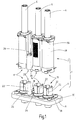
- the Fig. 1 shows a perspective view of a first embodiment of a connector system 1 with a first connector part 2 and a second connector part 4 in not yet mated condition.
- the first connector part 2 is designed as a three-pole plug, with the three each unipolar electrical lines 6, which are each designed as a cable with a cable sheath, are electrically connected to the second connector part 4.
- a housing 48 for example, in the Fig. 17 and 18 arranged socket-shaped contact members, which are brought into electrical contact upon mating of the first and second connector part 2, 4 with preferably cylindrical contact pins 22 in the second connector part 4.
- the second connector part 4 is arranged in the exemplary embodiment on a housing wall 8 of an aggregate, for example on an alternator or on an electric motor.
- the first and second connector part 2, 4 each have three load contacts 12, 14, 16, which serve for an electrical connection of the electrical lines 6, and a pilot contact 18 of the in the Fig. 1 only the associated pilot contact of the second connector part 4 is partially visible.
- the two connector parts 2, 4 also have components 20 for a guide of the first connector part 2 when mating with the second connector part 4, wherein on the part of the second connector part 4 as a guide component at least partially cylindrical pin 24 is arranged, at its the first connector part 2 facing end is tapered, in particular rounded and / or has a conical surface.
- the two connector parts 2, 4 components for locking the first connector part 2 on the second connector part 4 which has a connecting screw 26 in the embodiment on the side of the first connector part 2 and on the part of second connector part 4 a threaded bore 28.
- the second connector part 4 is preferably releasably secured by means of a terminal block 30 on the housing wall 8, screwed in the embodiment.
- the first connector part 2 has a wiring running parallel to the plug-in direction.
- the Fig. 2 shows a second embodiment of a connector system 1, wherein the first connector part 102 has an angled to the direction of insertion extending wiring of the electrical lines 6, in particular an angled 90 ° cable routing.
- the second connector part 4 is identical to the second connector part 4 of the first embodiment of the Fig. 1 constructed, in particular, both a first connector part 2 extending parallel to the plug direction wiring, as in the Fig. 1 shown, as well as a first connector part 102 with angled to the direction of insertion extending wiring with the same second connector part 4 can be plugged together.
- the components of a first component group with components for the pilot contact 18, and the components for the three load contacts 12, 14, 16 are independent of a number of load contacts 12, 14, 16 determined pole number of the first connector part 102, in particular, the pilot contact 18th always identical, regardless of whether it is a one-, two- or n-pin connector; the same applies to the load contacts 12, 14, 16 in the straight version and the load contacts 212, 214 in the angled design ( Fig. 3 ).
- the components 20 for a guide during mating and the components 26 for fixing the first connector part 2 to the second connector part 4 are formed independently of the number of poles.
- the housing 48 of the first connector part 2 has one of the number of load contacts 12, 14, 16 certain number of poles determined number of receiving chambers for the components of the load contacts 12, 14, 16.
- the arranged within the housing 48 components of the load contacts 12, 14, 16 are constructed identically.
- the components 20 for guiding the mating, as well as the components of the pilot contact 18 and the attachment 26 are between the in the Fig. 1 and 2 arranged on the left arranged first load contact 12 and the middle load contact 14. In one embodiment, this arrangement is maintained even with two- or multi-pin connectors, In particular, the arrangement of the components 20 for the guide, the pilot contact 18 and the connecting means 26 is always independent of the number of poles of the connector system 1 between two adjacent load contacts 12, 14 are arranged.
- the second connector part 4 has a contact pin 22 in the axial direction superior sleeve-shaped portion 32 which can serve for further guidance of the first connector part 2, 102 when mating with the second connector part 4.
- the sleeve-shaped portion 32 has an opening 34 extending in the plug-in direction, which is open in the direction of the first plug connection part 2, 102 and in the exemplary embodiment is formed by a slot.
- the first connector part 2, 102 projects with its housing 48 beyond an end 36 of the opening 34 facing the second connector part 4. This is followed by an annular and preferably cylindrical or conical section 38, to which a sealing means can be brought into abutment in the assembled state and thereby seals the contact elements of the connector system 1.
- the sleeve-shaped portion 32 preferably integrally formed guide means 40, which extend in the embodiment in the axial direction and are formed as webs, and by the mating a further guidance and / or reverse polarity is guaranteed.
- the guide means or webs and the associated recesses may form a customizable coding of the connector system 1.
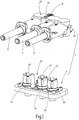
- the Fig. 3 shows a perspective view of a third embodiment of a connector system 201 with a two-pole first connector part 202 and a two-pole second connector part 204, wherein the first connector part 202 is an angled connector, in which the wiring runs perpendicular to the direction of insertion.
- the Fig. 4 shows a side view of the connector system 201 of Fig. 3
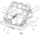
- the Fig. 5 shows in a opposite the 3 and 4 enlarged view of a perspective view of the connector system 201 in a partially separated state.
- the first connector part 202 has a bow-shaped actuating element 242, with which the two connector parts 202, 204 from the in the 3 and 4 fully assembled state in one in the Fig. 5 illustrated state in which the pilot contact 218 is either already separated, or at least in a complete transfer of the actuating element 242 in a relation to the representation in the 3 and 4 is rotated by 90 ° position, the load contacts 212, 214 but still electrically connected.
- the actuating element 242 is pivotable about a preferably integrally formed by the first connector part 202 axle journal 244, whereupon a introduced in the actuator 242, for example, by a groove cam 246 is moved along a arranged on the second connector part 204 guide pin 250 such that the first connector part 202th lifts from the second connector part 204.
- the actuator 242 can in his in the 3 and 4 shown first end position and / or in a contrast rotated by 90 ° second end position releasably be locked. Due to the lever action of the actuating element 242, only a small actuating force is required both when opening and when closing the connection between the first and the second plug connection part 202, 204. This is particularly advantageous at high temperatures and / or soiling environmental conditions.
- the first plug connection part 202 and the second plug connection part 204 have mutually corresponding latching means 252, 254, wherein in the exemplary embodiment the latching means 252 of the first plug connection part 202 is formed by a recess in a housing wall, in which engages the corresponding latching means 254 of the second plug connection part 204 when plugging while locked with the opening.
- the locking means 254 of the second connector part 204 has a run-on slope, by means of which the locking means 254 is deflected during mating and snaps back as soon as the locking means 254 engages in the opening in the first connector part 202.
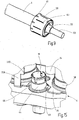
- the Fig. 6 shows a perspective view of an enlarged detail in the region of the locking means 252, 254 in a state in which the first connector part 202 are completely mated with the second connector part 204 and both the load contacts 212, 214 and the pilot contact 218 are closed.
- the Fig. 7 shows an enlarged section in the region of the latching elements 252, 254 in a state in which the first connector part 202 so far from the second connector part 204 is released that the pilot contact 218 is disconnected, the load contacts 212, 214 but still connected.
- the latching element 252 of the first plug connection part has a first opening section 256 which is slightly larger than a first section 258 of the second latching element 254 but smaller than a second section 260 of the second latching element 254 Fig. 7
- the second portion 260 shown in abutment against the housing 48 of the first connector part 2 and blocks a complete removal of the first connector part 202 of the second connector part 204. Only by a deflection of the second locking element 254, for example by means of a tool, the second portion 260 in Covering with a second, opposite the first opening portion larger second opening portion 262 of the first locking element 254 brought slightly larger than the second portion 260 of the second locking element 254, so that the first connector part 202 can be removed from the second connector part 204.
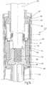
- the Fig. 8 shows a section of a section through the housing 48 of the first connector part 2 in a region in which the electrical line 6 shown in a view is connected to the first connector part 2.
- the cable 6 is a cable with an inner conductor 53, which is surrounded by an insulation 55, on the outside of a metallic conductive cable shield 57 is applied.
- the inner conductor 53 is provided with an electrical plug connection element 10 (described below). Fig. 17 . 18 ) electrically and mechanically connected.
- the connector part 2 which is a device 11 for electrically connecting the cable shield 57 of the electrical line 6 to the housing 48, further comprises a three-part fixing in the illustrated embodiment 81, 85, 87, by means of which the connecting element 78 and thus the inner conductor 53 at Occurrence of a tensile force on the line 6 is fixed immovably in the housing 48 by positive engagement.
- the connecting element 78 is at least partially sleeve-shaped and mechanically fixedly connected by clamping with the inner conductor 53, in particular with the inner conductor 53 pressed. The pressing takes place with the interposition of two contact plates 72, 74, which also form the contact member of the connector element 10 in one piece.
- the connecting element 78 has at least one end on a flange-like widening 84, which forms a form of a positive connection in the direction of the tensile force and preferably annular contact surface 79 for a first part 81 of the fixing.
- the first part 81 of the fixing element is sleeve-shaped and surrounds the Connecting element 78 and extends in the direction of an end facing away from the contact element of the connector element 10 beyond the connecting element 78 addition.
- the first part 81 of the fixing element with the interposition of a radially outwardly extending connecting line 83 for the cable shield 57 in contact with a second part 85 of the fixing, which is also sleeve-shaped and the line 6 receives in itself.
- the second part 85 has a contact surface for a third part 87 of the fixing element, which forms a positive connection with the housing 48 in the direction of the tensile force.
- the third part 87 of the fixing element is clamp-shaped in the exemplary embodiment, wherein the associated clip in a designated opening 89 (FIG. Fig. 1 ) is inserted into the housing 48 in a direction obliquely and in particular transversely to the direction of insertion or to the longitudinal direction of the line 6 and thereby locks the fixing element in the housing 48.
- this tensile force is transmitted via the inner conductor 53 to the connecting element 78, which in positive engagement with the first part 81 of the fixing, this in turn in positive engagement with the second part 85, and this in turn in positive engagement on the third part 87, wherein the third part 87 is in positive engagement with the housing 48.
- a firm connection between the conduit 6 and the housing 48 is provided, which is based only on positive engagement and is independent of frictional forces.
- the device 11 is part of a receiving chamber associated with each pole for each load contact 12, 14, 16, 212, 214 in each embodiment of the housing 48 of the first connector part 2.
- the device 11 may be formed the same for both straight connector and angled connectors except for the formation of the contact members.
- the device 11 also has an intermediate element 91, which may be made of a plastic.
- the intermediate element 91 can also be referred to as insulating sleeve.
- the intermediate element 91 comprises the connecting element 78 at least in sections and projects in the direction of the contact element of the plug connection element 10 beyond the connecting element 78.
- the intermediate member 91 integrally forms a sleeve-shaped guide portion 75 which upon mating of the first and second connector part 2, 4 in abutment against the sleeve-shaped portion 32 (FIGS. Fig. 1 ) of the second connector part 4 comes and is guided.
- the device 11 has a spring element 93, with which the connecting element 78 is biased in the housing 48 in the direction of the positive engagement with the fixing element, in the exemplary embodiment, it is biased in the direction of the first part 81 of the fixing.
- the spring element 93 is in this case on the one hand in contact with a radially outwardly projecting shoulder of the intermediate element 91 and on the other hand in contact with a radially inwardly projecting shoulder of the housing 48.
- the first part 81 of the fixing element has in a section between the positive engagement with the connecting element 78 and the positive engagement with the second part 85 or the connection line 83 for the cable shield 57, a locking means 95, with which the first part 81 during assembly of the device 11 with the intermediate element 91 can be latched.
- the latching means 95 is formed in the embodiment by a portion with a larger radial dimension, which can engage in a correspondingly shaped recess in the intermediate element 91 latching.
- the intermediate element 91 may have a slotted section at its end pointing away from the contact element of the plug connection element 10, and at the end thereof a run-on bevel 97 may be arranged for engagement of the first part 81.
- the second part 85 of the fixing projecting beyond the end of the housing 48 at its end facing away from the contact member of the connector element 10, whereby a guide of the electrical line 6 is given.
- a sealing element 99 is arranged, which forms a plurality of sealing surfaces in the axial direction and in the exemplary embodiment has the cross-sectional shape of a corrugated tube.
- the sealing element 99 also provides guidance of the line 6 in the housing 48.
- the third part 87 of the fixing element is radially outwardly in contact with the inner surface of the housing 48 by a further sealing element 77; the third part 87 may also be referred to as a lock.
- the Fig. 9 2 shows a perspective view of a section of the line 6 with the insulation 55 deposited at the conductor end and the inner conductor 53 exposed thereby.
- the cable shield 57 (FIG. Fig. 8 ) electrically contacted by a substantially annular shield member 59.
- the shielding element 59 may be formed from a flat and punched sheet metal part and has in the molded State an annular portion with which the shield member 59 can be brought into abutment against the line 6 to be connected.
- the shielding element 59 in the circumferential direction preferably distributed evenly radially projecting contact tongues 61 which can be brought into abutment against the housing 48 and thereby contact the housing 48 electrically.
- the shielding element 59 has slots 63 extending in the direction of the inner conductor 53 and preferably distributed uniformly in the circumferential direction, by means of which the eddy currents occurring in the shielding element 59 are reduced.
- the Fig. 10 shows a perspective view of a portion of the conduit 6 with an alternative embodiment of a shield member 159 which is formed in several parts.
- a first part 131 of the shielding element 159 may be formed as a stamped / bent part and have a continuous axial slot 133 through which the first part 131 is resiliently deformable; the first part 131 may also be referred to as a shield contact.
- the Fig. 11 shows a top view of the first part 131 and the Fig. 12 a side view of a section through the first part 131.
- the first part 131 forms a contact element for the cable shield 57 of the line 6. Die Fig.
- FIG. 13 shows a section through a second part 135 of the shield member 159, with the cable shield 57 is electrically contacted and in particular an electrically conductive connection between the cable shield 57 and the first part 131 can be produced; the second part 135 may also be called a screen crimp.
- the Fig. 14 shows a section of a section through a second embodiment of a housing 148 of the first connector part 2. As far as compared to the embodiment of Fig. 8 are designated matching features, reference numerals are used to the Amount 100 compared to in the Fig. 8 used reference numerals are increased.
- a shield member 159 is inserted, as shown in the FIGS. 10 to 13 is shown.
- the shield element 159 comprises a third part 137, with which the cable shield 157 of the line 106 is mechanically fixed, in particular crimped; the third part 137 may also be referred to as Stützcrimp.
- the third part 137 firmly encloses both the cable screen 157 on the insulation 155 and the cable outer jacket of the line 106.
- the portion of the third part 137, which encloses the insulation 155 or the cable shield 157, is axially spaced from the portion of the third part 137, which encloses the outer cable sheath.
- the embodiment of the housing 148 of Fig. 14 is like the embodiment of the Fig. 8 inside conical. Unlike the Fig. 8 is at the housing 148 of the Fig. 14 also the outer shape conical, since the wall thickness is approximately constant.
- the protruding and cut to a suitable length end of the cable shield 157 is folded over and is enclosed by the second part 135 of the shield member 159.
- the second part 135 is shaped such that its outer edge reaches almost to the inner surface of the housing 148.
- this has a stiffening means 139, which is formed in the embodiment by an annular recess.
- the second part 135 has a preferably circumferential and at right angles to the longitudinal axis extending edge portion 141, which is set back in the embodiment of the axial ends of the second part 135, wherein the distance to one axial end is smaller than the opposite other axial end ,
- the second part 185 of the fixing element is supported positively in the axial direction; the second part 185 may also be referred to as a sealing sleeve.
- the first part 181 of the fixing element is positively supported in the axial direction, wherein the support of the first part 181 is radially inward of the support of the second part 185 of the fixing element; the first part 181 may also be referred to as a spacer sleeve.
- the second part 135 is rotationally symmetrical to its longitudinal axis. By turning over the cable shield 157, this has a defined distance from the main contact.
- the first part 131 of the shield member 159 is arranged.
- it consists of a slotted sleeve which, in the undeformed state, has a shape which deviates from the cylindrical shape, in particular is conical.
- the first part 131 on its outer surface preferably integrally formed by embossing and circumferentially preferably uniformly distributed contact tongues 161 or contact tabs, with which the housing 148 is electrically contacted.
- the first part 131 on its inside preferably integrally formed by embossing and circumferentially preferably uniformly distributed second contact tongues 143 or contact lugs with which the second part 135 of the shield member 159 is electrically contacted.
- the first part 131 is brought approximately in a cylindrical shape, since during assembly, the cable of the line 106 with the parts mounted thereon in the housing 148 is inserted. By the restoring force of the first part 131 this is in safe electrical contact on the one hand on the inner surface of the housing 148 and on the other hand on the second part 135 of the shield member 159.
- integrally formed stop means for abutment on the second part 135 are arranged in particular for bearing on the edge portion 141 of the second part 135, by which it is ensured that the first part 131 is axially in a defined position in the housing 148, in particular in a defined position relative to the second part 135 and thus with respect to the line 106
- the stop means may be formed by the second contact tongues 143.
- a defined contact of the first part 131 is ensured both radially outward on the housing 148 and radially inward.
- a radially inner second contact tongue 143 is arranged, wherein the connecting line between mutually associated contact tongues 161, 143 extends parallel to the longitudinal axis of the line 106 in order to ensure a corresponding current flow direction for the cable shield current. Due to the small distance of the sleeve-shaped first part 131 from the housing 148, a good capacitive coupling of the shield contact is ensured.
- the outer diameter of the second part 135 in the region of the edge portion 141 is only slightly smaller than the clear width of the housing 148 minus the thickness of the first part 131, so that in this area a clearance of less than 2 mm, in particular less than 1.2 mm and preferably less than 0.8 mm; in the embodiment, the distance is about 0.5 mm.
- a Radial movement of the line 106, in particular of the cable with the parts mounted thereon, ie also with the second part 135, moves the first part 131 at that axial position at which the first part 131 electrically contacts the second part 135, likewise the movement through the abutment of the first part 131 on the inside of the housing 148 experiences a stop.
- the first part 131 does not undergo any movement in the radial direction, because the first part 131 is centered by the abutment of the contact tongues 161 within the housing 148. This results in a pivoting movement of the first part 131, which has the advantage that thereby takes place a relative movement at the contact points, thereby cleaning the contact surfaces.
- the end portion of the first part 131, with which the first part 131 is in communication with the second part 135, is at an angle of more than 0.2 ° and less than 6 °, in particular more than 0.5 °, with respect to the adjacent part and bent less than 4 ° and preferably more than 0.5 ° and less than 2.5 ° inward so that this end portion undergoes no bending stress in a pivoting movement of the first part 131, which would be detrimental to the occurrence of vibration.
- the length of the bent portion is less than 30% of the length of the first part 131, in particular less than 20% and preferably less than 15%. In the exemplary embodiment, the length of the bent portion is up to +/- 25% equal to the length of the second contact tongues 143.
- the Fig. 15 shows a perspective view of a section of the second connector part 4 in the region of the pilot contact 18.
- An electrically conductive, loosely applied sleeve-shaped portion 64 on the plug-in unit for the pilot contact 18 has at its the terminal block 30th facing the end of a flange-like widening 66, on which one of the terminal block 30 preferably integrally formed contact nose 65 can be brought into abutting contact, wherein the contact nose 65 resiliently relative to the terminal block 30 can be deflected and fixed the sleeve-shaped portion 64 to the housing wall 8 and the Screen connection ensures.
- the contact tabs 65 are down holders for the conductive and end-bent sleeve with flange-like widening 66, which places the shield connection on the potential of the unit.
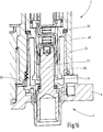
- the Fig. 16 shows a section of a section through the housing 48 of the first connector part 2 and the housing wall 8 of the unit with the second connector element 4 in the assembled state.
- a seal 69 is arranged, in particular in contact with the annular portion 38 (FIGS. Fig. 1 ) of the sleeve-shaped portion 32 on the one hand and the housing 48 on the other.
- the guide section 75 of the first plug connection element 2 projects in the direction of the second plug connection element 4 beyond the contact elements of the first plug connection element 2, so that these are disposed in the first plug connection element 2 in a touch-proof manner.
- One of the terminal block 30 preferably integrally formed dome 67 is in contact-bearing contact with the housing 48 of the first connector element 2.
- the terminal block 30 in the region of the passage of the load contacts 12, 14, 16 thereby form-locking counter-holding the housing 48th
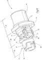
- the Fig. 17 shows a perspective view of a first embodiment of a connector element 10 for use in the above-described first connector part 2.
- the connector element 10 has two formed by shaped electrically conductive sheet metal strips contact plates 72, 74, each having a connection portion 76, which in the illustration of Fig. 17 is concealed by the sleeve-shaped connecting element 78, for the electrical connection of the connector element 10 to the electrical line 6.
- the contact plates 72, 74 a contact portion 82, for a releasable electrical connection of the connector element 10 with a contact member of the second connector element 4.
- the contact plates 72, 74 have a compensation section 80 arranged between the connection section 76 and the contact section 82 for elastic deflection of the contact section 82 relative to the connection section 76.
- the two contact plates 72, 74 are bent partially circular, in particular each approximately semicircular, and are fixed by the sleeve 78 in the position shown.
- the connecting element 78 has, at its end facing the contact section 82, a support element 84 formed by a flange-like widening, by means of which the connecting element 78 can be supported on a counter element.
- the connecting element and thus the line 6 can be fixed in the housing 48 of the first connector element 2 when a tensile force occurs by positive engagement. Tensile forces or, for example, vibrations are thereby not forwarded to the contact section 82, as a result of which the electrical connection is particularly reliable.
- connection section 76 to be connected line 6 is permanently connected by crimping the sleeve 78, in particular by the molding of a hexagon, securely connected to the connector element 10.
- the support member 84 causes the forces and / or deformations occurring during crimping to be kept away from the compensating section 80.
- the support element 84 is preceded by a first spreading portion 73, so that the connecting element 78 has a two- or multi-stage widening.
- the two contact plates 72, 74 are each meandering bent, starting first from the terminal portion 76, the first contact plate 72 forms a U-shaped loop and in the axial direction then the second contact plate 74 is a substantially equal sized U-shaped loop forms. Subsequently, the two contact plates 72, 74 extend further into the contact section 82. At the bending points of the meander-shaped loops, the two contact plates 72, 74 each have at least one recess 86, through which the strip width of the contact plate 72, 74 is reduced and thereby the flexural rigidity is reduced.
- the two contact plates 72, 74 tool engagement surfaces 90 which are formed in the embodiment by holes, by means of which the contact plates 72, 74 can be fixed during bending of the loops; alternatively or additionally, the holes may also be provided to reduce the flexural rigidity.
- the contact plates 72, 74 in the region of the parallel legs 88 stop means 92 which in Embodiment formed by the contact plates 72, 74 integrally formed and bent by 90 ° lugs.
- the two contact plates 72, 74 are bent in a V-shape and enclose an angle between 60 and 150 °, preferably between 75 and 120 °.
- the contact plates 72, 74 have a bending shape which deviates from the cross-sectional contour of the contact element of the second plug connection part 4, resulting in one or preferably two line contacts per contact plate 72, 74.
- a foreign spring 94 is placed, with the contact plates 72, 74 in contact-bearing contact with the contact member of the associated second connector part 4 are preserved.
- the foreign spring 94 has an annular portion 96, which limits the maximum expansion of the contact plates 72, 74 in the contact portion 82.
- the annular portion 96 are in the axial direction spring arms 98 from which are bent or bent in the undeformed initial state inwardly and apply the contact force.
- two spring arms 98 are arranged on opposite sides.
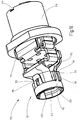
- the Fig. 18 shows a perspective view of a second embodiment of a connector element 110 for use in the first connector part described above 2.
- the first and second contact plates 172, 174 outwardly projecting lugs 111, 113, which together a guide and a stop for form the attachment of the foreign spring 194.
- the annular portion 115 of the foreign spring 194 is disposed on a second plug connection part 4 facing the end. From the annular portion 115 are on opposite sides guide means 117 out, which are introduced when attaching the foreign spring 194 between the two lugs 111, 113.
- the guide means 117 have a rounded or bevelled end portion.
- the guide means 117 alternatively or additionally form spacers which prevent excessive compression of the two contact plates 172, 174.
- the annular portion 115 are on opposite sides locking means 119, which cooperate with corresponding locking means 121 of the contact plates 172, 174.
- the latching means 119 of the foreign spring 194 have an opening or depression, into which engage the locking means 121, for example, a knob, formed integrally, for example by embossing of the contact plates 172, 174 integrally.
- the annular portion 115 terminates at the end substantially flush with the contact plates 172, 174 from.
- the contact plates 172, 174 form at the end an insertion bevel 125 for the contact pin 22 (FIG. Fig. 1 ).
- Each of the contact sheets 172, 174 has two by its shape Line contacts 123 for the contact-making system on the contact pin 22.
- the connecting element 178 has, in the region of the connection section, in particular at its connection section-side end, an adjusting means 127, by means of which the position of the connection element with respect to the contact plates 172, 174 is adjustable.
- the adjusting means 127 may be formed by a recess, in which immediately after the insertion of the contact plates 172, 174 a corresponding position fixing is impressed, so that the connecting element 178 is held only in a predetermined angular position on the contact plates 172, 174 and in the further assembly a twist protection is guaranteed.
- the Fig. 19 shows an embodiment of a connector element 210 for an angle plug.
- one of the contact plates 274 is only cranked and does not form a complete meander loop.
- the insertion of a contact pin 22 takes place transversely to the longitudinal direction of the plug connection element 210 determined by the succession of connection section 276, compensation section 280 and contact section 282.
- the foreign spring 294 is produced as a stamped / bent part and placed on the contact section 282.
- the Fig. 20 shows a further embodiment of a connector element 310 for an angle plug.
- the foreign spring 394 has two legs, each with at least one latching means 319, which cooperate with corresponding latching means 321 of the contact plates 372, 374.
- the locking means 319 of the Foreign spring 394 an opening or depression, in which engage integrally formed, for example, by embossing of the contact plates 372, 374 locking means 321 latching.
- the contact plates 372, 374 form at the end an insertion bevel 325 for the contact pin 22 of the second connector part 4.
- Each of the contact plates 372, 374 has by its shape two line contacts 323 for the contact-bearing system on the contact pin 22.
- At least one of the contact plates 372, 374 has a preferably integrally formed stop means 329, by means of which the contact plates 372, 374 are insertable only up to a corresponding stop in the connecting element 378; the corresponding stop can be formed by the transition from the support element 384 to the first widened portion 373 on the inside of the connecting element 378.
- a secure electrical connection is provided by the provision of a total of four line-shaped electrical contacts.
- the compensating section 80, 280 ensures a secure contact of the contact section 82, 282 with all four contact lines, in particular a compensation of a parallel offset or an inclined position of the contact member to be contacted is ensured.
- the high current carrying capacity is due to the direct contact of a large cross-sectional area having contact plates 72, 74 on the Contact pin 22 provided; the required flexibility of the contact sheets 72, 74 is provided by the balancing section 80, 280, which is formed separately from the contact point and the connection with the line 6.
Claims (15)
- Elément (10) de connexion enfichable, comprenant au moins deux tôles (72, 74) de contact, formées de bandes de tôle conformées conductrices de l'électricité, qui ont chacune une partie (76) de raccordement pour le raccordement électrique de l'élément (10) de connexion enfichable à une ligne (6) électrique et une partie (82) de contact, constituée d'une pièce avec la partie (76) de raccordement pour une liaison électrique, pouvant être défaite, de l'élément (10) de connexion enfichable à un élément de connexion associé, caractérisé en ce que les au moins deux tôles (72, 74) de contact ont, disposée entre la partie (76) de raccordement et la partie (82) de contact, une partie (80) de compensation pour une déviation élastique de la partie (82) de contact par rapport à la partie (76) de raccordement, en ce que la partie (76) de raccordement, la partie (80) de compensation et la partie (82) de contact sont constituées d'une seule pièce par les bandes (72, 74) de tôle et en ce que les tôles (72, 74) de contact sont, dans la partie (76) de raccordement, entourées d'un élément (78) de connexion en forme de manchon au moyen duquel, dans un état initial, les tôles (72, 74) de contact sont immobilisées l'une par rapport à l'autre en leur position.
- Elément (10) de connexion enfichable suivant la revendication 1, caractérisé en ce que, lors du raccordement de la ligne (6) électrique au moyen de l'élément (78) de connexion, un sertissage des tôles (72, 74) de contact avec la ligne (6) électrique peut être produit.
- Elément (10) de connexion enfichable suivant la revendication 2, caractérisé en ce que l'élément (78) de connexion s'étend au-delà de la région de sertissage.
- Elément (10) de connexion enfichable suivant l'une des revendications 1 à 3, caractérisé en ce que l'élément (78) de connexion a un élément (84) d'appui, par lequel les forces, se produisant lors de la liaison de l'élément (10) de connexion enfichable à la ligne (6), peuvent être tenues éloignées de la partie (82) de contact.
- Elément (10) de connexion enfichable suivant la revendication 1 ou l'une des revendications précédentes, caractérisé en ce qu'au moins l'une des tôles (72, 74) de contact, dans la partie (80) de compensation, a une rigidité à la flexion réduite.
- Elément (10) de connexion enfichable suivant la revendication 1 ou l'une des revendications précédentes, caractérisé en ce qu'au moins l'une des tôles (72, 74) de contact est sinueuse dans la partie (80) de compensation.
- Elément (10) de connexion enfichable suivant la revendication 1 ou l'une des revendications précédentes, caractérisé en ce qu'au moins l'une des tôles (72, 74) de contact a, dans la partie (80) de compensation, un moyen (92) de butée, constitué de préférence d'une seule pièce, pour limiter la déviation de la partie (82) de contact par rapport à la partie (76) de raccordement.
- Elément (10) de connexion enfichable suivant la revendication 1 ou l'une des revendications précédentes, caractérisé en ce qu'au moins une tôle (72, 74) de contact a, dans la partie (82) de contact, une forme de section transversale, qui s'écarte de la forme de section transversale d'un organe de contact de l'élément de connexion associé, en étant notamment en forme de V ou en forme de U, et en formant ainsi, lors de l'enfichage avec l'élément de connexion associé, deux contacts électriques linéaires.
- Elément (10) de connexion enfichable suivant la revendication 1 ou l'une des revendications précédentes, caractérisé en ce que les tôles (72, 74) de contact forment, dans la partie (82) de contact, un logement d'enfichage d'un organe de contact de l'élément de connexion associé.
- Elément (10) de connexion enfichable suivant la revendication 1 ou l'une des revendications précédentes, caractérisé en ce qu'il est disposé, dans la partie (82) de contact, un ressort (94) indépendant, par lequel les tôles (72, 74) de contact peuvent être maintenues, en application directe donnant un contact, sur l'élément de connexion associé.
- Elément (10) de connexion enfichable suivant la revendication 10, caractérisé en ce que le ressort (94) indépendant a une partie (96) annulaire, qui délimite la largeur maximum des tôles (72, 74) de contact, et a au moins un bras (98), qui fait saillie de la partie (96) annulaire et qui applique la force de contact.
- Elément (10) de connexion enfichable suivant la revendication 10 ou 11, caractérisé en ce que le ressort (94) indépendant a des moyens (68) de guidage, au moyen desquels le ressort (94) indépendant peut, en étant guidé sur les tôles (72, 74) de contact, être enfiché dans un évidement entre les tôles (72, 74) de contact.
- Elément (10) de connexion enfichable suivant l'une des revendications 10 à 12, caractérisé en ce qu'au moins une tôle (72, 74) de contact a un moyen (70) de butée pour le ressort (94) indépendant, moyen qui est disposé de préférence à la transition de la partie (82) de contact à la partie (80) de compensation.
- Elément (110) de connexion enfichable suivant l'une des revendications 10 à 13, caractérisé en ce qu'au moins une tôle (172, 174) de contact a un moyen (121) d'encliquetage, qui coopère à encliquetage avec un moyen (119) d'encliquetage du ressort (194) indépendant.
- Partie (2) de connexion enfichable, ayant plusieurs éléments (10) de connexion enfichables suivant la revendication 1 ou l'une des revendications précédentes, caractérisé en ce que les éléments (10) de connexion enfichables sont disposés sous la forme de parties identiques dans une enveloppe (48) commune.
Applications Claiming Priority (2)
| Application Number | Priority Date | Filing Date | Title |
|---|---|---|---|
| DE201010014980 DE102010014980A1 (de) | 2010-04-14 | 2010-04-14 | Elektrisches Steckverbindungselement und Steckverbindungsteil mit mehreren Steckverbindungselementen |
| PCT/EP2011/001838 WO2011128075A1 (fr) | 2010-04-14 | 2011-04-13 | Élément de connexion enfichable électrique et pièce de connexion enfichable comportant plusieurs éléments de connexion enfichable |
Publications (2)
| Publication Number | Publication Date |
|---|---|
| EP2559112A1 EP2559112A1 (fr) | 2013-02-20 |
| EP2559112B1 true EP2559112B1 (fr) | 2018-09-05 |
Family
ID=44063979
Family Applications (1)
| Application Number | Title | Priority Date | Filing Date |
|---|---|---|---|
| EP11714943.5A Active EP2559112B1 (fr) | 2010-04-14 | 2011-04-13 | Élément de connexion enfichable électrique et pièce de connexion enfichable comportant plusieurs éléments de connexion enfichable |
Country Status (5)
| Country | Link |
|---|---|
| US (1) | US9004955B2 (fr) |
| EP (1) | EP2559112B1 (fr) |
| CA (1) | CA2796069C (fr) |
| DE (1) | DE102010014980A1 (fr) |
| WO (1) | WO2011128075A1 (fr) |
Families Citing this family (6)
| Publication number | Priority date | Publication date | Assignee | Title |
|---|---|---|---|---|
| DE102010014981A1 (de) * | 2010-04-14 | 2011-10-20 | Pfisterer Kontaktsysteme Gmbh | Vorrichtung zum elektrischen Verbinden eines Kabels, insbesondere Steckverbindungsteil |
| DE102010045780A1 (de) * | 2010-09-17 | 2012-03-22 | Rohde & Schwarz Gmbh & Co. Kg | Kalibriereinheit für ein Messgerät |
| JP6750540B2 (ja) * | 2017-03-10 | 2020-09-02 | 株式会社オートネットワーク技術研究所 | シールド端子及びシールドコネクタ |
| TWI657632B (zh) * | 2018-03-19 | 2019-04-21 | 戴健郎 | 連接器 |
| US10862228B2 (en) * | 2018-05-08 | 2020-12-08 | Amphenol Corporation | Cable connector and method of terminating a cable |
| JP1622367S (fr) * | 2018-06-21 | 2019-01-21 |
Family Cites Families (80)
| Publication number | Priority date | Publication date | Assignee | Title |
|---|---|---|---|---|
| US2175583A (en) * | 1938-04-02 | 1939-10-10 | Jesse M White | Terminal for electrical conductors |
| US2297336A (en) * | 1940-05-15 | 1942-09-29 | Jesse M White | Electrical connector |
| US2644145A (en) * | 1950-06-27 | 1953-06-30 | American Phenolic Corp | Pressure contact |
| US2727219A (en) * | 1951-09-17 | 1955-12-13 | Thomas & Betts Corp | Electric spade terminal receptacle |
| US3242458A (en) * | 1963-11-19 | 1966-03-22 | Triple A Specialty Co | Flexible ignition cable terminal connector |
| US3335392A (en) * | 1965-07-19 | 1967-08-08 | Essex Wire Corp | Terminal construction |
| US3573718A (en) * | 1968-09-16 | 1971-04-06 | Amp Inc | Miniature electrical connector |
| US3539954A (en) * | 1969-07-29 | 1970-11-10 | Itt | Removable electrical connector filter assembly |
| NL7001611A (fr) * | 1970-02-05 | 1971-08-09 | ||
| US3697931A (en) * | 1971-01-04 | 1972-10-10 | Illinois Tool Works | Electrical plug contact |
| US3771113A (en) * | 1971-10-28 | 1973-11-06 | Eltra Corp | Spring action terminal with locked barrel |
| US3918789A (en) * | 1973-11-30 | 1975-11-11 | Neal R Davis | Bendable plug wire-to-spark plug connector |
| US4010538A (en) * | 1975-07-01 | 1977-03-08 | Amp Incorporated | Phono plug |
| US4334732A (en) | 1979-04-12 | 1982-06-15 | Nixdorf Computer Ag | Electrical connector unit |
| CH653178A5 (de) * | 1981-02-10 | 1985-12-13 | Cdm Connectors Dev & Mfg Ag | Kontaktanordnung mit einem wickelpfosten. |
| US4846736A (en) * | 1982-04-30 | 1989-07-11 | Prestolite Wire Corporation | Ignition wire terminal |
| DE3302824A1 (de) * | 1983-01-28 | 1984-08-02 | Grote & Hartmann | Zusatzverriegelungselement fuer rundsteckkontakte |
| US4778404A (en) * | 1983-12-27 | 1988-10-18 | Amp Incorporated | Spring terminal |
| IT1179895B (it) * | 1984-12-28 | 1987-09-16 | Burndy Electra Spa | Elemento di contatto elettrico femmina con sforzo di accoppiamento relativamente ridotto e relativo complesso connettore |
| US4666232A (en) * | 1986-01-13 | 1987-05-19 | Don Shyu | Plug for a car antenna |
| US4710140A (en) * | 1987-03-03 | 1987-12-01 | Cooper Industries, Inc. | Pliers crimpable terminal |
| US4934967A (en) * | 1987-12-15 | 1990-06-19 | Amp Incorporated | Socket for pin grid array |
| US5186658A (en) * | 1988-11-30 | 1993-02-16 | Amp Incorporated | Electrical contact |
| US5041027A (en) * | 1989-07-21 | 1991-08-20 | Cooper Power Systems, Inc. | Cable splice |
| US5015195A (en) * | 1990-03-13 | 1991-05-14 | Thomas & Betts Corporation | Plug and socket electrical connection assembly |
| US5033982A (en) * | 1990-05-31 | 1991-07-23 | Sun Microstamping, Inc. | Electrical connector |
| US5035638A (en) * | 1990-08-16 | 1991-07-30 | Amp Incorporated | Electrical terminal which has means to provide a reliable electrical connection |
| US5011440A (en) * | 1990-09-10 | 1991-04-30 | Lee Chun Te | Wire connector |
| EP0477663B1 (fr) * | 1990-09-28 | 1996-08-14 | Siemens Aktiengesellschaft | Pièce de contact |
| USD337990S (en) * | 1991-06-17 | 1993-08-03 | Gte Products Corporation | Antenna connector |
| EP0607485B1 (fr) * | 1993-01-21 | 1996-10-09 | Molex Incorporated | Connecteur de câble coaxial modulaire |
| US5376022A (en) * | 1993-12-06 | 1994-12-27 | Safco Corporation | Electrical connector |
| FR2719163A1 (fr) * | 1994-04-22 | 1995-10-27 | Amp France | Borne anti-corrosion par usure, destinée à recevoir une borne complémentaire. |
| US5575694A (en) * | 1995-04-19 | 1996-11-19 | Boston Scientific Corporation | Electrical connector for attachment to a medical device |
| US5634829A (en) * | 1995-04-20 | 1997-06-03 | Interlock Corporation | Low engagement force terminal with easy off-axis disengagement |
| US5562506A (en) * | 1995-06-05 | 1996-10-08 | Osram Sylvania Inc. | Radio connector |
| US6261134B1 (en) * | 1995-10-20 | 2001-07-17 | Itt Manufacturing Enterprises, Inc. | One-piece hooded socket contact and method of producing same |
| US5658175A (en) * | 1995-10-05 | 1997-08-19 | Itt Corporation | One-piece hooded socket contact and method of producing same |
| US5967856A (en) * | 1995-12-20 | 1999-10-19 | Berg Technology, Inc. | Connector with spring contact member and shorting means |
| DE19548168C2 (de) * | 1995-12-22 | 1997-10-16 | Delphi Automotive Systems Gmbh | Einteiliges Kontaktelement |
| JPH09185970A (ja) * | 1995-12-28 | 1997-07-15 | Yazaki Corp | 雌端子 |
| ES2144869T3 (es) * | 1996-06-17 | 2000-06-16 | Framatome Connectors Int | Casquillo de conector de enchufe. |
| US5911603A (en) * | 1996-07-22 | 1999-06-15 | The Whitaker Corporation | Single piece electrical receptacle terminal for mating with a pin contact |
| FR2758214B1 (fr) | 1997-01-08 | 1999-01-29 | Cinch Connecteurs Sa | Organe de contact electrique femelle |
| JPH10241807A (ja) | 1997-02-14 | 1998-09-11 | Molex Inc | 電気コネクタ |
| DE19734524C2 (de) * | 1997-08-08 | 1999-07-29 | Framatome Connectors Int | Zylinderförmiger Buchsenkontakt |
| US5980335A (en) * | 1998-03-27 | 1999-11-09 | Molex Incorporated | Electrical terminal |
| SE517582C2 (sv) * | 1999-03-31 | 2002-06-25 | Berg Connectors Sweden Ab | Kontakthylsa |
| DE19918326A1 (de) | 1999-04-22 | 2000-10-26 | Delphi Tech Inc | Elektrische Anschlußbuchse |
| US6083059A (en) * | 1999-05-28 | 2000-07-04 | Ant Precision Industry Co., Ltd. | Structure of a terminal |
| DE19943045A1 (de) * | 1999-09-09 | 2001-04-05 | Pfisterer Kontaktsyst Gmbh | Vorrichtung zum Steckverbinden elektrischer Leiter |
| US6296525B1 (en) * | 2000-01-07 | 2001-10-02 | J. D'addario & Company, Inc. | Electrical plug and jack connectors |
| US6533617B1 (en) * | 2000-01-07 | 2003-03-18 | J. D'addario & Company, Inc. | Electrical plug connectors |
| US6626708B2 (en) * | 2001-03-30 | 2003-09-30 | Tyco Electronics Corporation | Single piece spring contact |
| US6629865B2 (en) * | 2001-12-07 | 2003-10-07 | Delphi Technologies, Inc. | Zero terminal insertion force electrical connection assembly |
| DE10202637C1 (de) | 2002-01-24 | 2003-08-14 | Ims Connector Systems Gmbh | Steckverbinder |
| JP4278129B2 (ja) * | 2002-06-20 | 2009-06-10 | 日本圧着端子製造株式会社 | ソケットコネクタ |
| US6848954B2 (en) * | 2003-01-20 | 2005-02-01 | Tyco Electronics Amp Gmbh | Electrical contact element |
| US6955561B2 (en) * | 2003-02-26 | 2005-10-18 | Osram Sylvania Inc. | Inline connector |
| DE20304748U1 (de) * | 2003-03-24 | 2004-07-29 | Ghw Grote & Hartmann Gmbh | Elektrisches Hochstromkontaktelement |
| DE102004015344A1 (de) * | 2004-03-30 | 2005-10-20 | Kostal Kontakt Systeme Gmbh | Elektrisches Nullkraftsteckverbindungsteil |
| ATE389960T1 (de) * | 2004-06-30 | 2008-04-15 | Tyco Electronics Nederland Bv | Verbinder für elektronische bauteile |
| BRPI0513887A (pt) * | 2004-08-03 | 2008-05-20 | Tyco Electronics Amp Gmbh | tomada elétrica e método de encaixe da tomada |
| DE102004062879A1 (de) * | 2004-12-27 | 2006-07-06 | Lear Corp., Southfield | Elektrisches Kontaktelement sowie Kontaktierungseinrichtung mit Kontaktelement |
| CA2573845C (fr) * | 2006-04-20 | 2009-11-24 | Thomas & Betts International, Inc. | Elements de connecteur electrique |
| DE102006020955B4 (de) * | 2006-05-05 | 2010-12-02 | Lumberg Connect Gmbh | Andruckkontakt und Andruckverbinder |
| US7347741B1 (en) * | 2007-01-16 | 2008-03-25 | Tyco Electronics Corporation | Contact with locking lances |
| US8007314B2 (en) * | 2007-05-02 | 2011-08-30 | John Mezzalingua Associates, Inc. | Compression connector for coaxial cable |
| US7527532B2 (en) * | 2007-05-15 | 2009-05-05 | Fci Americas Technology, Inc. | Battery contact |
| US7607952B2 (en) * | 2007-05-15 | 2009-10-27 | Fci Americas Technology, Inc. | Battery contact |
| DE102007042194A1 (de) | 2007-08-29 | 2009-03-05 | Pfisterer Kontaktsysteme Gmbh & Co. Kg | Elektrisches Steckverbinderelement |
| US7762857B2 (en) * | 2007-10-01 | 2010-07-27 | Fci Americas Technology, Inc. | Power connectors with contact-retention features |
| US7575439B2 (en) * | 2007-12-03 | 2009-08-18 | Cheng Uei Precision Industry Co., Ltd. | Speaker connector |
| US7963782B2 (en) * | 2008-02-25 | 2011-06-21 | Cooper Technologies Company | Separable connector system with a position indicator |
| US7942697B2 (en) * | 2008-04-25 | 2011-05-17 | Times Microwave Systems, Inc. | Electrical interconnection systems and methods of assembling the same |
| US8079875B2 (en) * | 2009-06-08 | 2011-12-20 | Cheng Uei Precision Industry Co., Ltd. | Battery connector with serpentine contacts |
| JP5215472B2 (ja) * | 2009-08-20 | 2013-06-19 | 行田電線株式会社 | 防水コネクタ |
| EP2339696A1 (fr) * | 2009-12-22 | 2011-06-29 | General Electric Company | Assemblage de connecteur électrique |
| DE102010014981A1 (de) * | 2010-04-14 | 2011-10-20 | Pfisterer Kontaktsysteme Gmbh | Vorrichtung zum elektrischen Verbinden eines Kabels, insbesondere Steckverbindungsteil |
| US7980894B1 (en) * | 2010-08-23 | 2011-07-19 | Tyco Electronics Corporation | Coaxial connector with a cable receptor with an outer contact |
-
2010
- 2010-04-14 DE DE201010014980 patent/DE102010014980A1/de not_active Withdrawn
-
2011
- 2011-04-13 US US13/261,453 patent/US9004955B2/en active Active
- 2011-04-13 WO PCT/EP2011/001838 patent/WO2011128075A1/fr active Application Filing
- 2011-04-13 EP EP11714943.5A patent/EP2559112B1/fr active Active
- 2011-04-13 CA CA2796069A patent/CA2796069C/fr active Active
Also Published As
| Publication number | Publication date |
|---|---|
| WO2011128075A9 (fr) | 2011-12-22 |
| WO2011128075A1 (fr) | 2011-10-20 |
| EP2559112A1 (fr) | 2013-02-20 |
| US9004955B2 (en) | 2015-04-14 |
| DE102010014980A1 (de) | 2011-10-20 |
| US20130035003A1 (en) | 2013-02-07 |
| CA2796069C (fr) | 2017-02-07 |
| CA2796069A1 (fr) | 2011-10-20 |
Similar Documents
| Publication | Publication Date | Title |
|---|---|---|
| EP2843764B1 (fr) | Borne de connexion électrique à ressort | |
| EP2810341B1 (fr) | Contact tubulaire pour un connecteur électrique à force d'insertion nulle | |
| EP2559112B1 (fr) | Élément de connexion enfichable électrique et pièce de connexion enfichable comportant plusieurs éléments de connexion enfichable | |
| EP3396793B1 (fr) | Corps de contact pour connecteur à fiche | |
| EP2442403B1 (fr) | Borne de connexion sans vis | |
| EP3394936B1 (fr) | Connecteur enfichable | |
| EP2559105B1 (fr) | Dispositif de connexion électrique d'un câble, en particulier pièce de connexion enfichable | |
| WO2016062476A2 (fr) | Ensemble servant à connecter deux conducteurs électriques | |
| EP2577805A1 (fr) | Élément de contact pour ensemble connecteur | |
| BE1026171B1 (de) | Anschlusseinrichtung zum Anschließen eines Schirmleiters einer elektrischen Leitung an einen Erdungsabschnitt | |
| EP2559110B1 (fr) | Dispositif de connexion électrique d'un câble, en particulier pièce de connexion enfichable avec un élément de contact au blindage | |
| DE102007042194A1 (de) | Elektrisches Steckverbinderelement | |
| EP2243198B1 (fr) | Connecteur enfichable coaxial coudé | |
| WO2012080083A1 (fr) | Dispositif de raccordement à un moyen d'actionnement mobile | |
| EP2467904B1 (fr) | Élément de contact | |
| WO2023186209A1 (fr) | Module de mise à la terre destiné à être reçu dans un cadre modulaire de connecteur à fiche métallique et qui met à la terre ledit cadre modulaire | |
| WO2023078502A1 (fr) | Appareil de support de contact, dispositif de connexion, actionneur, insert de connecteur enfichable et procédé d'installation, et système de connexion de câble | |
| DE102011103738B4 (de) | Kupplungsverbinder und Set aus Steckverbindern | |
| EP1720222B1 (fr) | Connecteur électrique, notamment pour des systèmes d' allumage d' airbag | |
| EP4000139A1 (fr) | Élément de contact | |
| DE102015106058B4 (de) | Steckverbindersystem | |
| DE102016000384B4 (de) | Mehrpoliger elektrischer Verbinder | |
| DE102010014979A1 (de) | Elektrisches Steckverbindungssystem | |
| DE19750250A1 (de) | Lösbare elektrische Klemme | |
| DE202010007145U1 (de) | Elektrischer Steckverbinder |
Legal Events
| Date | Code | Title | Description |
|---|---|---|---|
| PUAI | Public reference made under article 153(3) epc to a published international application that has entered the european phase |
Free format text: ORIGINAL CODE: 0009012 |
|
| 17P | Request for examination filed |
Effective date: 20121002 |
|
| AK | Designated contracting states |
Kind code of ref document: A1 Designated state(s): AL AT BE BG CH CY CZ DE DK EE ES FI FR GB GR HR HU IE IS IT LI LT LU LV MC MK MT NL NO PL PT RO RS SE SI SK SM TR |
|
| DAX | Request for extension of the european patent (deleted) | ||
| GRAP | Despatch of communication of intention to grant a patent |
Free format text: ORIGINAL CODE: EPIDOSNIGR1 |
|
| STAA | Information on the status of an ep patent application or granted ep patent |
Free format text: STATUS: GRANT OF PATENT IS INTENDED |
|
| INTG | Intention to grant announced |
Effective date: 20180511 |
|
| GRAS | Grant fee paid |
Free format text: ORIGINAL CODE: EPIDOSNIGR3 |
|
| GRAA | (expected) grant |
Free format text: ORIGINAL CODE: 0009210 |
|
| STAA | Information on the status of an ep patent application or granted ep patent |
Free format text: STATUS: THE PATENT HAS BEEN GRANTED |
|
| AK | Designated contracting states |
Kind code of ref document: B1 Designated state(s): AL AT BE BG CH CY CZ DE DK EE ES FI FR GB GR HR HU IE IS IT LI LT LU LV MC MK MT NL NO PL PT RO RS SE SI SK SM TR |
|
| REG | Reference to a national code |
Ref country code: GB Ref legal event code: FG4D Free format text: NOT ENGLISH |
|
| REG | Reference to a national code |
Ref country code: CH Ref legal event code: EP |
|
| REG | Reference to a national code |
Ref country code: AT Ref legal event code: REF Ref document number: 1038942 Country of ref document: AT Kind code of ref document: T Effective date: 20180915 |
|
| REG | Reference to a national code |
Ref country code: DE Ref legal event code: R096 Ref document number: 502011014693 Country of ref document: DE |
|
| REG | Reference to a national code |
Ref country code: IE Ref legal event code: FG4D Free format text: LANGUAGE OF EP DOCUMENT: GERMAN |
|
| REG | Reference to a national code |
Ref country code: NL Ref legal event code: FP |
|
| REG | Reference to a national code |
Ref country code: SE Ref legal event code: TRGR |
|
| REG | Reference to a national code |
Ref country code: NO Ref legal event code: T2 Effective date: 20180905 |
|
| REG | Reference to a national code |
Ref country code: LT Ref legal event code: MG4D |
|
| PG25 | Lapsed in a contracting state [announced via postgrant information from national office to epo] |
Ref country code: BG Free format text: LAPSE BECAUSE OF FAILURE TO SUBMIT A TRANSLATION OF THE DESCRIPTION OR TO PAY THE FEE WITHIN THE PRESCRIBED TIME-LIMIT Effective date: 20181205 Ref country code: LT Free format text: LAPSE BECAUSE OF FAILURE TO SUBMIT A TRANSLATION OF THE DESCRIPTION OR TO PAY THE FEE WITHIN THE PRESCRIBED TIME-LIMIT Effective date: 20180905 Ref country code: GR Free format text: LAPSE BECAUSE OF FAILURE TO SUBMIT A TRANSLATION OF THE DESCRIPTION OR TO PAY THE FEE WITHIN THE PRESCRIBED TIME-LIMIT Effective date: 20181206 Ref country code: RS Free format text: LAPSE BECAUSE OF FAILURE TO SUBMIT A TRANSLATION OF THE DESCRIPTION OR TO PAY THE FEE WITHIN THE PRESCRIBED TIME-LIMIT Effective date: 20180905 Ref country code: FI Free format text: LAPSE BECAUSE OF FAILURE TO SUBMIT A TRANSLATION OF THE DESCRIPTION OR TO PAY THE FEE WITHIN THE PRESCRIBED TIME-LIMIT Effective date: 20180905 |
|
| PG25 | Lapsed in a contracting state [announced via postgrant information from national office to epo] |
Ref country code: AL Free format text: LAPSE BECAUSE OF FAILURE TO SUBMIT A TRANSLATION OF THE DESCRIPTION OR TO PAY THE FEE WITHIN THE PRESCRIBED TIME-LIMIT Effective date: 20180905 Ref country code: LV Free format text: LAPSE BECAUSE OF FAILURE TO SUBMIT A TRANSLATION OF THE DESCRIPTION OR TO PAY THE FEE WITHIN THE PRESCRIBED TIME-LIMIT Effective date: 20180905 Ref country code: HR Free format text: LAPSE BECAUSE OF FAILURE TO SUBMIT A TRANSLATION OF THE DESCRIPTION OR TO PAY THE FEE WITHIN THE PRESCRIBED TIME-LIMIT Effective date: 20180905 |
|
| PG25 | Lapsed in a contracting state [announced via postgrant information from national office to epo] |
Ref country code: EE Free format text: LAPSE BECAUSE OF FAILURE TO SUBMIT A TRANSLATION OF THE DESCRIPTION OR TO PAY THE FEE WITHIN THE PRESCRIBED TIME-LIMIT Effective date: 20180905 Ref country code: PL Free format text: LAPSE BECAUSE OF FAILURE TO SUBMIT A TRANSLATION OF THE DESCRIPTION OR TO PAY THE FEE WITHIN THE PRESCRIBED TIME-LIMIT Effective date: 20180905 Ref country code: CZ Free format text: LAPSE BECAUSE OF FAILURE TO SUBMIT A TRANSLATION OF THE DESCRIPTION OR TO PAY THE FEE WITHIN THE PRESCRIBED TIME-LIMIT Effective date: 20180905 Ref country code: RO Free format text: LAPSE BECAUSE OF FAILURE TO SUBMIT A TRANSLATION OF THE DESCRIPTION OR TO PAY THE FEE WITHIN THE PRESCRIBED TIME-LIMIT Effective date: 20180905 Ref country code: ES Free format text: LAPSE BECAUSE OF FAILURE TO SUBMIT A TRANSLATION OF THE DESCRIPTION OR TO PAY THE FEE WITHIN THE PRESCRIBED TIME-LIMIT Effective date: 20180905 Ref country code: IS Free format text: LAPSE BECAUSE OF FAILURE TO SUBMIT A TRANSLATION OF THE DESCRIPTION OR TO PAY THE FEE WITHIN THE PRESCRIBED TIME-LIMIT Effective date: 20190105 |
|
| PG25 | Lapsed in a contracting state [announced via postgrant information from national office to epo] |
Ref country code: PT Free format text: LAPSE BECAUSE OF FAILURE TO SUBMIT A TRANSLATION OF THE DESCRIPTION OR TO PAY THE FEE WITHIN THE PRESCRIBED TIME-LIMIT Effective date: 20190105 Ref country code: SK Free format text: LAPSE BECAUSE OF FAILURE TO SUBMIT A TRANSLATION OF THE DESCRIPTION OR TO PAY THE FEE WITHIN THE PRESCRIBED TIME-LIMIT Effective date: 20180905 Ref country code: SM Free format text: LAPSE BECAUSE OF FAILURE TO SUBMIT A TRANSLATION OF THE DESCRIPTION OR TO PAY THE FEE WITHIN THE PRESCRIBED TIME-LIMIT Effective date: 20180905 |
|
| REG | Reference to a national code |
Ref country code: DE Ref legal event code: R097 Ref document number: 502011014693 Country of ref document: DE |
|
| PLBE | No opposition filed within time limit |
Free format text: ORIGINAL CODE: 0009261 |
|
| STAA | Information on the status of an ep patent application or granted ep patent |
Free format text: STATUS: NO OPPOSITION FILED WITHIN TIME LIMIT |
|
| PG25 | Lapsed in a contracting state [announced via postgrant information from national office to epo] |
Ref country code: DK Free format text: LAPSE BECAUSE OF FAILURE TO SUBMIT A TRANSLATION OF THE DESCRIPTION OR TO PAY THE FEE WITHIN THE PRESCRIBED TIME-LIMIT Effective date: 20180905 |
|
| 26N | No opposition filed |
Effective date: 20190606 |
|
| PG25 | Lapsed in a contracting state [announced via postgrant information from national office to epo] |
Ref country code: SI Free format text: LAPSE BECAUSE OF FAILURE TO SUBMIT A TRANSLATION OF THE DESCRIPTION OR TO PAY THE FEE WITHIN THE PRESCRIBED TIME-LIMIT Effective date: 20180905 |
|
| REG | Reference to a national code |
Ref country code: CH Ref legal event code: PL |
|
| REG | Reference to a national code |
Ref country code: BE Ref legal event code: MM Effective date: 20190430 |
|
| PG25 | Lapsed in a contracting state [announced via postgrant information from national office to epo] |
Ref country code: MC Free format text: LAPSE BECAUSE OF FAILURE TO SUBMIT A TRANSLATION OF THE DESCRIPTION OR TO PAY THE FEE WITHIN THE PRESCRIBED TIME-LIMIT Effective date: 20180905 Ref country code: LU Free format text: LAPSE BECAUSE OF NON-PAYMENT OF DUE FEES Effective date: 20190413 |
|
| PG25 | Lapsed in a contracting state [announced via postgrant information from national office to epo] |
Ref country code: CH Free format text: LAPSE BECAUSE OF NON-PAYMENT OF DUE FEES Effective date: 20190430 Ref country code: LI Free format text: LAPSE BECAUSE OF NON-PAYMENT OF DUE FEES Effective date: 20190430 |
|
| PG25 | Lapsed in a contracting state [announced via postgrant information from national office to epo] |
Ref country code: BE Free format text: LAPSE BECAUSE OF NON-PAYMENT OF DUE FEES Effective date: 20190430 |
|
| PG25 | Lapsed in a contracting state [announced via postgrant information from national office to epo] |
Ref country code: TR Free format text: LAPSE BECAUSE OF FAILURE TO SUBMIT A TRANSLATION OF THE DESCRIPTION OR TO PAY THE FEE WITHIN THE PRESCRIBED TIME-LIMIT Effective date: 20180905 |
|
| PG25 | Lapsed in a contracting state [announced via postgrant information from national office to epo] |
Ref country code: IE Free format text: LAPSE BECAUSE OF NON-PAYMENT OF DUE FEES Effective date: 20190413 |
|
| PG25 | Lapsed in a contracting state [announced via postgrant information from national office to epo] |
Ref country code: CY Free format text: LAPSE BECAUSE OF FAILURE TO SUBMIT A TRANSLATION OF THE DESCRIPTION OR TO PAY THE FEE WITHIN THE PRESCRIBED TIME-LIMIT Effective date: 20180905 |
|
| PG25 | Lapsed in a contracting state [announced via postgrant information from national office to epo] |
Ref country code: HU Free format text: LAPSE BECAUSE OF FAILURE TO SUBMIT A TRANSLATION OF THE DESCRIPTION OR TO PAY THE FEE WITHIN THE PRESCRIBED TIME-LIMIT; INVALID AB INITIO Effective date: 20110413 Ref country code: MT Free format text: LAPSE BECAUSE OF FAILURE TO SUBMIT A TRANSLATION OF THE DESCRIPTION OR TO PAY THE FEE WITHIN THE PRESCRIBED TIME-LIMIT Effective date: 20180905 |
|
| PG25 | Lapsed in a contracting state [announced via postgrant information from national office to epo] |
Ref country code: MK Free format text: LAPSE BECAUSE OF FAILURE TO SUBMIT A TRANSLATION OF THE DESCRIPTION OR TO PAY THE FEE WITHIN THE PRESCRIBED TIME-LIMIT Effective date: 20180905 |
|
| PGFP | Annual fee paid to national office [announced via postgrant information from national office to epo] |
Ref country code: NL Payment date: 20230422 Year of fee payment: 13 |
|
| PGFP | Annual fee paid to national office [announced via postgrant information from national office to epo] |
Ref country code: NO Payment date: 20230421 Year of fee payment: 13 Ref country code: IT Payment date: 20230428 Year of fee payment: 13 Ref country code: FR Payment date: 20230425 Year of fee payment: 13 Ref country code: DE Payment date: 20230426 Year of fee payment: 13 |
|
| PGFP | Annual fee paid to national office [announced via postgrant information from national office to epo] |
Ref country code: SE Payment date: 20230421 Year of fee payment: 13 Ref country code: AT Payment date: 20230426 Year of fee payment: 13 |
|
| PGFP | Annual fee paid to national office [announced via postgrant information from national office to epo] |
Ref country code: GB Payment date: 20230420 Year of fee payment: 13 |