EP2467904B1 - Kontaktelement - Google Patents
Kontaktelement Download PDFInfo
- Publication number
- EP2467904B1 EP2467904B1 EP10739869.5A EP10739869A EP2467904B1 EP 2467904 B1 EP2467904 B1 EP 2467904B1 EP 10739869 A EP10739869 A EP 10739869A EP 2467904 B1 EP2467904 B1 EP 2467904B1
- Authority
- EP
- European Patent Office
- Prior art keywords
- contact
- cover
- cylindrical
- sleeve
- female
- Prior art date
- Legal status (The legal status is an assumption and is not a legal conclusion. Google has not performed a legal analysis and makes no representation as to the accuracy of the status listed.)
- Active
Links
Images
Classifications
-
- H—ELECTRICITY
- H01—ELECTRIC ELEMENTS
- H01R—ELECTRICALLY-CONDUCTIVE CONNECTIONS; STRUCTURAL ASSOCIATIONS OF A PLURALITY OF MUTUALLY-INSULATED ELECTRICAL CONNECTING ELEMENTS; COUPLING DEVICES; CURRENT COLLECTORS
- H01R13/00—Details of coupling devices of the kinds covered by groups H01R12/70 or H01R24/00 - H01R33/00
- H01R13/02—Contact members
- H01R13/15—Pins, blades or sockets having separate spring member for producing or increasing contact pressure
- H01R13/187—Pins, blades or sockets having separate spring member for producing or increasing contact pressure with spring member in the socket
-
- H—ELECTRICITY
- H01—ELECTRIC ELEMENTS
- H01R—ELECTRICALLY-CONDUCTIVE CONNECTIONS; STRUCTURAL ASSOCIATIONS OF A PLURALITY OF MUTUALLY-INSULATED ELECTRICAL CONNECTING ELEMENTS; COUPLING DEVICES; CURRENT COLLECTORS
- H01R13/00—Details of coupling devices of the kinds covered by groups H01R12/70 or H01R24/00 - H01R33/00
- H01R13/46—Bases; Cases
- H01R13/53—Bases or cases for heavy duty; Bases or cases for high voltage with means for preventing corona or arcing
Definitions
- the invention relates to an electrical contact element according to the preamble of patent claim 1.
- the invention therefore relates to a cylindrical socket contact element comprising a hyperbolic contact cage, which is also referred to as RADSOK connector.
- RADSOK connectors are particularly characterized in that their contact area is cage-like and is designed as a cylindrical hyperbolic hollow body, which preferably has contact blades in the longitudinal direction or contact spring arms for contacting with a plug pin.
- the hyperbolic contact cages are usually formed as a stamped / bent part of a sheet and then introduced into a cylindrical tube sleeve.
- cylindrical socket contact elements which are also stamped from a metal sheet, wherein the cylindrical bushing body is generated by rolling or bending and rolling of the punching plate.
- Such a connector is for example from the DE 197 34 524 C2 known.
- a cylindrical socket contact consisting of a contact part and a connector, shown, wherein the contact part has a cylinder jacket and the cylinder jacket has at least one stamped from the jacket contact spring tongue, which dips into the receiving area of the cylinder, so that a pin contact with this spring contact elements can, as soon as this is plugged into the cylindrical socket contact.
- the cylindrical high current contact socket is thereby introduced into an opening of a conductor track element and pressed between two pressing elements with a corresponding contour with the planar conductor track element. This creates a relatively flat-fitting socket contact, which however has a socket contact element open on both sides.
- the electrical contact element relates to a cylindrical socket contact, which is non-positively and positively connected to a contact holder on the outer jacket of the cylindrical socket contact by means of thermal shrinkage.
- the aforementioned contact systems are all such that they can find applications in technical applications in which a limited space is available with respect to the plugging direction of the socket contact.
- the length of the socket contact determines the required contact coverage, as well as the connector housing (if any) the overall size of the connector system.
- a further embodiment of a female contact element, the preamble of the main claim, is from the WO 00/70713 known.
- Another object of the present invention is to further develop a contact system such that at the same time there is the possibility to connect a suitable for the application cable.
- a cylindrical high-current contact socket in which a flat housing cover simultaneously fulfill the function for the housing seal and the function for the electrical connection to a cable.
- the heat can be removed via this housing cover.
- the cylindrical high-current contact socket has a metallic, the female member closing contact cap, which has a connection region for contacting with an electrical line.
- the metallic contact cover is fixed by means of a butt weld at one end of the cylindrical socket contact.
- the contact cover is formed as a substantially rectangular, thin metal sheet.
- the metal sheet thus has a sealing portion and a connection portion.
- the sealing portion is formed by the fact that the butt weld between the cylindrical socket contact and the contact cover is formed without interruption.
- the weld is externally mounted circumferentially on the cylindrical socket contact.
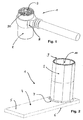
- Fig. 1 a known female contact element 1 is shown.
- the socket contact element 1 consists essentially of a cylindrical metallic contact sleeve 2, in which a hyperbolic contact grid 3 is introduced with contact blades 30.
- a contact holder 8 is attached on the outer jacket of the cylindrical socket contact 1.
- This known from the prior art socket contact element 1 is open on both sides and therefore not sealed against environmental conditions such as dirt, dust and moisture.
- FIG. 2 A first embodiment of the present invention is disclosed in Fig. 2 shown.
- a socket contact element 1 with a cylindrical contact sleeve 2 is shown.
- the female contact member 1 is open on the side of the contact hole 9 so as to be electrically connected to a pin connector.
- the contact cover 4 has a connection section 5 and a sealing section 6.
- the sealing section 6 is in direct contact with the cylindrical contact sleeve 2 and is connected thereto by means of a Weld 7 connected. It is essential that the weld 7 is arranged without interruption at the junction between the cylindrical contact sleeve 2 and the contact cover 4.
- the weld 7 is formed as an uninterrupted butt weld and can be welded directly to the contact cover 4 without changing the contours of the cylindrical contact sleeve 2.
- electrical cables of different geometry and with different cross sections can be welded in a freely scalable manner.
- the contact cover 4 is made of a highly conductive metallic material, which is also well weldable.
Landscapes
- Connector Housings Or Holding Contact Members (AREA)
Description
- Die Erfindung betrifft ein elektrisches Kontaktelement gemäß dem Oberbegriff des Patentanspruch 1.
- Die Erfindung betrifft daher ein zylinderförmiges Buchsenkontaktelement, umfassend einen hyperbolischen Kontaktkäfig, welche auch als RADSOK-Steckverbinder bezeichnet wird. Solche RADSOK-Steckverbinder sind insbesondere dadurch gekennzeichnet, dass ihr Kontaktbereich käfigartig ausgebildet ist und als zylindrischer hyperbolischer Hohlkörper gestaltet ist, der vorzugsweise in Längsrichtung Kontaktlamellen besitzt oder Kontaktfederarme zur Kontaktierung mit einem Steckerstift.
- Aus Kostengründen werden die hyperbolischen Kontaktkäfige üblicherweise als Stanz/-Biegeteil aus einem Blech geformt und anschließend in eine zylinderförmige Rohrhülse eingebracht.
- Im Stand der Technik sind verschiedene zylinderförmige Buchsenkontaktelemente bekannt, die ebenfalls aus einem Blech gestanzt sind, wobei der zylinderförmige Buchsenkörper durch Rollen beziehungsweise Biegen und Rollen des Stanzbleches erzeugt wird.
- Eine solche Steckverbindung ist beispielsweise aus der
DE 197 34 524 C2 bekannt. Hier wird ein zylinderförmiger Buchsenkontakt, bestehend aus einem Kontaktteil und einem Anschlussteil, gezeigt, wobei das Kontaktteil einen Zylindermantel aufweist und der Zylindermantel mindestens eine aus dem Mantel gestanzten Kontaktfederzunge aufweist, welche in den Aufnahmebereich des Zylinders eintaucht, so dass ein Steckerstift mit diesem Federkontaktelementen kontaktieren kann, sobald dieser in den zylinderförmigen Buchsenkontakt gesteckt wird. - Im Stand der Technik offenbart die
DE 10 2005 062 709 A1 ein Kontaktsystem, welches zwischen einer zylinderförmigen Hochstromkontaktbuchse und einem planaren Leiterbahnelement mit zwei gegenüberliegenden Flachseiten angeordnet ist. - Die zylinderförmige Hochstromkontaktbuchse wird dabei in eine Öffnung eines Leiterbahnelementes eingebracht und zwischen zwei Anpresselementen mit einer entsprechenden Kontur mit dem planaren Leiterbahnelement verpresst. Hierdurch entsteht ein relativ flachbauender Buchsenkontakt, welcher allerdings über ein beidseitig offenes Buchsenkontaktelement verfügt.
- Ein weiteres im Stand der Technik bekanntes Steckverbindersystem mit einer zylinderförmigen Hochstromkontaktbuchse ist aus der
DE 10 2007 055 040 A1 bekannt. Hier betrifft das elektrische Kontaktelement einen zylinderförmigen Buchsenkontakt, welcher mit einem Kontakthalter kraft- und formschlüssig am Außenmantel des zylinderförmigen Buchsenkontaktes mittels thermischen Aufschrumpfens verbunden ist. - Die zuvor genannten Kontaktsysteme sind alle derart beschaffen, dass diese in technischen Applikationen Anwendungen finden können, bei denen ein begrenzter Bauraum in Bezug auf die Steckrichtung des Buchsenkontaktes zur Verfügung steht. Im Prinzip bestimmt die Länge des Buchsenkontaktes die notwenige Kontaktüberdeckung, sowie das Steckverbindergehäuse (sofern vorhanden) die Gesamtgröße des Steckverbindersystems.
- Zunehmend werden gattungsgemäße Steckverbinder der zuvor genannten Art in Anwendungen eingesetzt, bei denen die klimatischen Umgebungsbedingungen hohe Anforderungen an das Steckverbindersystem stellen. Insbesondere im Bereich von elektrischen Antrieben und Hybridfahrzeugen werden Hochstromkontaktbuchsen im Motorraum oder an exponierten Stellen eingesetzt, bei denen Schmutz und Flüssigkeiten das Steckverbindersystem belasten.
- Hierzu sind im Stand der Technik umfangreiche Lösungen für Steckverbindergehäuse bekannt, welche einerseits die Funktion der Berührsicherheit und andererseits die Funktion der Dichtung übernehmen. Insbesondere bei wasserdichten Anforderungen muss sicher gestellt sein, dass keine Feuchtigkeit in die Steckverbinderbuchse eindringen kann. Andererseits werden Hochstromkontaktbuchsen bei der Anwendung im Hochstrombereich erheblich thermisch belastet und es können Temperaturen oberhalb von 150° Celsius auftreten.
- Daraus ergeben sich Schwierigkeiten bezüglich der Auswahl der Kunststoffe, welche die Dichtfunktion des Steckverbindersystems bei solchen Temperaturen noch ausreichend erfüllen. Andererseits besteht die Problematik mit der Abführung von entstehender Wärme aus Wärmeverlusten im Steckverbindersystem. In beiden Problemfällen führt dies dazu, dass die im Stand der Technik bekannten Lösungen zum Abdichten des Steckverbinders einerseits und zur Erfüllung der Bauraumbedingungen andererseits nicht ausreichend erfüllt sind.
- Eine weitere Ausführung eines Buchsenkontaktelements, dem Oberbegriff des Hauptanspruchs entsprechend, ist aus der
WO 00/70713 - Es ist somit Aufgabe der vorliegenden Erfindung, ein zylinderförmiges Hochstromkontaktelement der gattungsgemäßen Art bereit zu stellen, welches gegenüber der Umgebung abgedichtet ist und gleichzeitig die thermische Wärme gut abführen kann.
- Weitere Aufgabe der vorliegenden Erfindung ist es, ein Kontaktsystem derart weiter zu entwickeln, dass gleichzeitig die Möglichkeit besteht, ein für die Applikation passendes Kabel anzuschließen.
- Da es insbesondere im Bereich der Automobilindustrie und damit der Elektromotorentechnik zunehmend von erheblicher Bedeutung ist, unter welchen wirtschaftlichen Bedingungen ein Steckverbindersystem herzustellen ist, muss darüber hinaus das Steckverbindersystem kostengünstig und auf einfachste Art und Weise herstellbar sein.
- Die zuvor genannten Aufgaben werden gelöst durch die Merkmale des Anspruch 1.
- In den Unteransprüchen sind bevorzugte Ausführungsformen der Erfindung gekennzeichnet.
- Erfindungsgemäß wird eine zylindrische Hochstromkontaktbuchse bereitgestellt, bei der ein flachbauender Gehäusedeckel gleichzeitig die Funktion für die Gehäusedichtung und die Funktion für die elektrische Anbindung zu einem Kabel erfüllen. Darüber hinaus kann die Wärme über diesen Gehäusedeckel abtransportiert werden.
- Anders ausgedrückt wurde ein solches Kontaktsystem gemäß der vorliegenden Erfindung bereitgestellt, bei dem die zylinderförmige Hochstromkontaktbuchse einen metallischen, das Buchsenelement verschließenden Kontaktdeckel aufweist, welcher über einen Anschlussbereich zum Kontaktieren mit einer elektrischen Leitung verfügt.
- Mit Vorteil wird der metallische Kontaktdeckel mittels einer Stumpfschweißnaht an einem Ende des zylindrischen Buchsenkontaktes befestigt.
- Ebenfalls mit Vorteil wird der Kontaktdeckel als ein im wesentlichen rechteckiges, dünnes Metallblech ausgebildet. Das Metallblech verfügt somit über einen Dichtabschnitt und einen Anschlussabschnitt. Der Dichtabschnitt wird dadurch gebildet, dass die Stumpfschweißnaht zwischen dem zylindrischen Buchsenkontakt und dem Kontaktdeckel unterbrechungsfrei ausgebildet ist.
- Hierdurch wird gewährleistet, dass das Kontaktsystem, also der zylindrische Buchsenkontakt wasserdicht durch den Kontaktdeckel verschlossen wird. Die Schweißnaht ersetzt dabei ein weiteres sonst notwendiges Dichtelement und macht daneben weitere Gehäusebauteile entbehrlich.
- Mit Vorteil wird die Schweißnaht außen umlaufend am zylindrischen Buchsenkontakt angebracht.
- Im folgenden wir die Erfindung anhand der Beschreibung eines Ausführungsbeispiels unter Bezugnahme auf die Zeichnungen näher erläutert. Dabei zeigen:
-
Fig. 1 einen im Stand der Technik bekannten zylinderförmigen Buchsenkontakt mit eingebrachten hyperbolischen Kontaktgitter; -
Fig. 2 eine erfindungsgemäße Ausführungsform eines zylindrischen Buchsenkontaktes. - In
Fig. 1 ist ein bekanntes Buchsenkontaktelement 1 dargestellt. Das Buchsenkontaktelement 1 besteht im wesentlichen aus einer zylinderförmigen metallischen Kontakthülse 2, in welche ein hyperbolisches Kontaktgitter 3 mit Kontaktlamellen 30 eingebracht ist. - Am Außenmantel des zylinderförmigen Buchsenkontaktes 1 ist ein Kontakthalter 8 angebracht. Dieses aus dem Stand der Technik bekannte Buchsenkontaktelement 1 ist beidseitig offen und daher gegenüber Umweltbedingungen wie Schmutz, Staub und Feuchtigkeit nicht abgedichtet.
- Ein erstes Ausführungsbeispiel der vorliegenden Erfindung ist in
Fig. 2 gezeigt. Hier ist ein Buchsenkontaktelement 1 mit einer zylinderförmigen Kontakthülse 2 dargestellt. - In die zylinderförmige Kontakthülse 2 wird ein hier nicht gezeigtes hyperbolisches Kontaktgitter 3 eingebracht.
- Das Buchsenkontaktelement 1 ist auf der Seite der Kontaktöffnung 9 offen, um mit einem Steckerstift elektrisch verbunden zu werden. Auf der der Kontaktöffnung 9 gegenüberliegenden Seite des Buchsenkontaktelementes 1 befindet sich ein im wesentlichen flacher Kontaktdeckel 4. Der Kontaktdeckel 4 verfügt über einen Anschlussabschnitt 5 und einen Dichtabschnitt 6. Der Dichtabschnitt 6 befindet sich in unmittelbarem Kontakt zur zylinderförmigen Kontakthülse 2 und ist mit dieser mittels einer Schweißnaht 7 verbunden. Wesentlich ist dabei, dass die Schweißnaht 7 unterbrechungsfrei an der Stoßstelle zwischen der zylinderförmigen Kontakthülse 2 und dem Kontaktdeckel 4 angeordnet ist. Vorzugsweise ist die Schweißnaht 7 als eine unterbrechungsfreie Stumpfschweißnaht ausgebildet und kann ohne Veränderung der Konturen an der zylinderförmigen Kontakthülse 2 unmittelbar am Kontaktdeckel 4 angeschweißt werden. Im Bereich des Anschlussabschnittes 5 können elektrische Kabel unterschiedlicher Geometrie und mit unterschiedlichem Querschnitt frei skalierbar angeschweißt werden. Es besteht darüber hinaus die Möglichkeit, mehrere voneinander getrennte Kabel am Anschlussabschnitt 5 des Kontaktdeckels 4 anzubringen. Mit Vorteil ist der Kontaktdeckel 4 aus einem hochleitfähigen metallischen Material hergestellt, welches darüber hinaus gut schweißbar ist.
-
- 1
- Buchsenkontaktelement
- 2
- zylinderförmige Kontakthülse
- 3
- hyperbolisches Kontaktgitter
- 4
- Kontaktdeckel
- 5
- Anschlussabschnitt
- 6
- Dichtabschnitt
- 7
- Schweißnaht
- 8
- Kontakthalter
- 9
- Kontaktöffnung
- 10
- Aufnahmeraum
- 30
- Kontaktlamellen
Claims (6)
- Buchsenkontaktelement (1) mit einem Aufnahmeraum (10) für einen Gegenkontakt umfassend eine zylinderförmige metallische Kontakthülse (2) sowie ein in einem Aufnahmemantel (10) der Kontakthülse (2) angeordnetes Kontaktgitter (3) zur elektrischen Kontaktierung des Gegenkontaktes, wobei die zylinderförmige Kontakthülse (2) an einem ihrer Enden durch einen metallischen Kontaktdeckel (4) vollständig gegenüber der Umgebung abgedichtet ist, dadurch gekennzeichnet, dass der Kontaktdeckel (4) im Bereich seines Dichtabschnittes (6) mittels einer unterbrechungsfreien, vollständig geschlossenen Schweißnaht (7) mit der zylinderförmigen Kontakthülse (2) verbunden ist.
- Buchsenkontaktelement (1) nach Anspruch 1, dadurch gekennzeichnet, dass der Kontaktdeckel (4) als ein im wesentlichen flaches Metallblech ausgebildet ist.
- Buchsenkontaktelement (1) gemäß Anspruch 1 oder 2, dadurch gekennzeichnet, dass der Kontaktdeckel (4) über einen elektrischen Anschlussabschnitt (5) und über einen Dichtabschnitt (6) verfügt.
- Buchsenkontaktelement (1) gemäß einem der vorhergehenden Ansprüche, dadurch gekennzeichnet, dass die Schweißnaht (7) außen umlaufend zwischen der Kontakthülse (2) und dem Kontaktdeckel (4) als Stumpfschweißnaht ausgebildet ist.
- Buchsenkontaktelement (1) gemäß einem der vorhergehenden Ansprüche, dadurch gekennzeichnet, dass das Kontaktgitter (3) als ein zylinderförmiges hyperbolisches Kontaktgitter mit einer Vielzahl von paarweise beabstandeten Kontaktlamellen (30) ausgebildet ist.
- Buchsenkontaktelement (1) gemäß einem der vorhergehenden Ansprüche, dadurch gekennzeichnet, dass der Kontaktdeckel (4) im Bereich seines Dichtabschnittes (6) die Kontakthülse (2) lückenlos verschließt.
Applications Claiming Priority (2)
| Application Number | Priority Date | Filing Date | Title |
|---|---|---|---|
| DE102009038092A DE102009038092B3 (de) | 2009-08-19 | 2009-08-19 | Buchsenkontaktelement |
| PCT/EP2010/004692 WO2011020549A1 (de) | 2009-08-19 | 2010-07-31 | Kontaktelement |
Publications (2)
| Publication Number | Publication Date |
|---|---|
| EP2467904A1 EP2467904A1 (de) | 2012-06-27 |
| EP2467904B1 true EP2467904B1 (de) | 2016-03-02 |
Family
ID=41667947
Family Applications (1)
| Application Number | Title | Priority Date | Filing Date |
|---|---|---|---|
| EP10739869.5A Active EP2467904B1 (de) | 2009-08-19 | 2010-07-31 | Kontaktelement |
Country Status (4)
| Country | Link |
|---|---|
| US (1) | US8529304B2 (de) |
| EP (1) | EP2467904B1 (de) |
| DE (2) | DE102009038092B3 (de) |
| WO (1) | WO2011020549A1 (de) |
Families Citing this family (4)
| Publication number | Priority date | Publication date | Assignee | Title |
|---|---|---|---|---|
| DE102009041919A1 (de) * | 2009-09-17 | 2011-03-31 | Tyco Electronics Amp Gmbh | Elektrisches Kontaktelement für Hochstromsteckverbinder und Herstellungsverfahren |
| DE102013004708A1 (de) * | 2013-03-19 | 2014-09-25 | Amphenol-Tuchel Electronics Gmbh | Elektrischer Litzenleiter mit Rundsteckkontaktbuchse |
| DE102013008497A1 (de) | 2013-05-18 | 2014-03-20 | Daimler Ag | Elektrischer Steckverbinder |
| DE102013217256B3 (de) * | 2013-08-29 | 2015-03-05 | Robert Bosch Gmbh | Buchse sowie Hochstromsteckverbindung, die eine solche Buchse aufweist |
Family Cites Families (15)
| Publication number | Priority date | Publication date | Assignee | Title |
|---|---|---|---|---|
| US2643319A (en) * | 1948-02-09 | 1953-06-23 | Hartford Nat Bank & Trust Co | Method of electric arc welding |
| US3218606A (en) * | 1964-01-20 | 1965-11-16 | Lockheed Aircraft Corp | Socket assembly for printed circuits |
| US3557428A (en) * | 1965-06-23 | 1971-01-26 | Connectronics Corp | Machines for manufacturing electric connector sockets |
| DE2359429B2 (de) * | 1973-08-29 | 1976-02-05 | Multi-Contact Ag, Basel (Schweiz) | Polanschluss |
| DE3817803C3 (de) * | 1988-05-26 | 1995-04-20 | Reinshagen Kabelwerk Gmbh | Elektrische Flachsteckverbindung |
| US5147229A (en) * | 1989-12-11 | 1992-09-15 | General Motors Corporation | High current electrical connector |
| DE19734524C2 (de) | 1997-08-08 | 1999-07-29 | Framatome Connectors Int | Zylinderförmiger Buchsenkontakt |
| US6268079B1 (en) * | 1998-11-25 | 2001-07-31 | Japan Storage Battery Co., Ltd. | Nonaqueous-electrolyte battery |
| WO2000070713A2 (en) * | 1999-05-12 | 2000-11-23 | K & K Stamping Company | Electrical connector and method of making the same |
| US6482049B1 (en) * | 1999-07-16 | 2002-11-19 | Amphenol Corporation | Radially resilient electrical connector |
| US7143779B2 (en) * | 2001-05-29 | 2006-12-05 | Parker Philip A | Pedestal hydrant |
| US6696199B2 (en) * | 2002-01-30 | 2004-02-24 | Japan Storage Battery Co., Ltd. | Battery |
| DE102005062709B4 (de) * | 2005-12-28 | 2009-04-23 | Amphenol-Tuchel Electronics Gmbh | Elektrische Verbindung |
| DE102006012434A1 (de) * | 2006-03-17 | 2007-09-20 | Amphenol-Tuchel Electronics Gmbh | Rastbarer Radsok-Steckverbinder |
| DE102007055040B4 (de) * | 2007-11-17 | 2013-08-29 | Amphenol-Tuchel Electronics Gmbh | Kontaktelement und Verfahren zur Herstellung eines Kontaktelementes |
-
2009
- 2009-08-19 DE DE102009038092A patent/DE102009038092B3/de active Active
- 2009-09-01 DE DE202009011839U patent/DE202009011839U1/de not_active Expired - Lifetime
-
2010
- 2010-07-31 EP EP10739869.5A patent/EP2467904B1/de active Active
- 2010-07-31 US US13/390,088 patent/US8529304B2/en active Active
- 2010-07-31 WO PCT/EP2010/004692 patent/WO2011020549A1/de not_active Ceased
Also Published As
| Publication number | Publication date |
|---|---|
| EP2467904A1 (de) | 2012-06-27 |
| DE202009011839U1 (de) | 2010-02-11 |
| US20120142234A1 (en) | 2012-06-07 |
| US8529304B2 (en) | 2013-09-10 |
| DE102009038092B3 (de) | 2010-12-09 |
| WO2011020549A1 (de) | 2011-02-24 |
Similar Documents
| Publication | Publication Date | Title |
|---|---|---|
| DE102012201123B3 (de) | Gewinkelter Hochvolt-Stecker | |
| DE202017101060U1 (de) | Steckverbinder, insbesondere für eine Hochstromanwendung | |
| EP2599163B1 (de) | Elektrische verbindung | |
| DE102011085700A1 (de) | Hochstrom-Steckverbinder für Kraftfahrzeuganwendungen | |
| EP2061119B1 (de) | Kontaktelement und Verfahren zur Herstellung eines Kontaktelementes | |
| EP2559112B1 (de) | Elektrisches steckverbindungselement und steckverbindungsteil mit mehreren steckverbindungselementen | |
| EP2559105B1 (de) | Vorrichtung zum elektrischen verbinden eines kabels, insbesondere steckverbindungsteil | |
| DE102013201125B4 (de) | Steckverbinder, Verwendung eines solchen Steckverbinders sowie Verfahren zur Herstellung einer elektrischen Verbindung in einem solchen Steckverbinder | |
| EP2559110B1 (de) | Vorrichtung zum elektrischen verbinden eines kabels, insbesondere steckverbindungsteil mit einem schirmkontaktelement | |
| DE102013013151A1 (de) | Vefahren zum elektrischen Verbinden der Litze eines elektrischen Leiters mit einem Leiteranschlusselement sowie konfektionierte elektrische Leitung | |
| EP2467904B1 (de) | Kontaktelement | |
| EP3662543A1 (de) | Elektrischer steckkontakt für hochstromanwendungen und steckverbindersystem für hochstromanwendungen | |
| EP2345110B1 (de) | Steckverbinder für ein sternvierer-kabel | |
| DE102012009877A1 (de) | Steckverbindergehäuse und Steckverbinder | |
| DE102013013368B4 (de) | Verfahren zur Herstellung einer elektrischen Verbindung sowie elektrische Verbindung | |
| EP1837955B1 (de) | Halteschutzbuchse für einen Steckverbinder | |
| DE102007057501A1 (de) | Vorrichtung zur elektrischen Kontaktierung eines Steuergeräts | |
| EP3477777B1 (de) | Elektrische leitung mit schirmausleitung | |
| DE102020111765B4 (de) | Elektrische Sicherungsvorrichtung, Verfahren zur Herstellung einer Sicherungsvorrichtung und ein Verfahren zum Betrieb einer elektrischen Sicherungsvorrichtung | |
| DE102009041919A1 (de) | Elektrisches Kontaktelement für Hochstromsteckverbinder und Herstellungsverfahren | |
| DE102009038091B3 (de) | Hochstromkontaktbuchse | |
| WO2019115026A1 (de) | Kontaktierungsvorrichtung und gekühlter steckbverbinder | |
| DE102023202154A1 (de) | Gehäusebaugruppe für einen Steckverbinder, Steckverbinder, Steckverbinderanordnung und Verfahren zum Montieren eines Steckverbinders | |
| DE102008031686A1 (de) | Verbesserte Halteschutzbuchse eines Steckverbinders | |
| DE102023202155B3 (de) | Gehäusebaugruppe für einen Steckverbinder, Steckverbinder, Steckverbinderanordnung und Verfahren zum Montieren eines Steckverbinders |
Legal Events
| Date | Code | Title | Description |
|---|---|---|---|
| PUAI | Public reference made under article 153(3) epc to a published international application that has entered the european phase |
Free format text: ORIGINAL CODE: 0009012 |
|
| 17P | Request for examination filed |
Effective date: 20120125 |
|
| AK | Designated contracting states |
Kind code of ref document: A1 Designated state(s): AL AT BE BG CH CY CZ DE DK EE ES FI FR GB GR HR HU IE IS IT LI LT LU LV MC MK MT NL NO PL PT RO SE SI SK SM TR |
|
| DAX | Request for extension of the european patent (deleted) | ||
| REG | Reference to a national code |
Ref country code: DE Ref legal event code: R079 Ref document number: 502010011140 Country of ref document: DE Free format text: PREVIOUS MAIN CLASS: H01R0013530000 Ipc: H01R0013187000 |
|
| GRAP | Despatch of communication of intention to grant a patent |
Free format text: ORIGINAL CODE: EPIDOSNIGR1 |
|
| RIC1 | Information provided on ipc code assigned before grant |
Ipc: H01R 13/187 20060101AFI20150708BHEP Ipc: H01R 13/53 20060101ALI20150708BHEP |
|
| INTG | Intention to grant announced |
Effective date: 20150813 |
|
| GRAS | Grant fee paid |
Free format text: ORIGINAL CODE: EPIDOSNIGR3 |
|
| GRAA | (expected) grant |
Free format text: ORIGINAL CODE: 0009210 |
|
| AK | Designated contracting states |
Kind code of ref document: B1 Designated state(s): AL AT BE BG CH CY CZ DE DK EE ES FI FR GB GR HR HU IE IS IT LI LT LU LV MC MK MT NL NO PL PT RO SE SI SK SM TR |
|
| REG | Reference to a national code |
Ref country code: GB Ref legal event code: FG4D Free format text: NOT ENGLISH |
|
| REG | Reference to a national code |
Ref country code: AT Ref legal event code: REF Ref document number: 778586 Country of ref document: AT Kind code of ref document: T Effective date: 20160315 Ref country code: CH Ref legal event code: EP |
|
| REG | Reference to a national code |
Ref country code: IE Ref legal event code: FG4D Free format text: LANGUAGE OF EP DOCUMENT: GERMAN |
|
| REG | Reference to a national code |
Ref country code: DE Ref legal event code: R096 Ref document number: 502010011140 Country of ref document: DE |
|
| REG | Reference to a national code |
Ref country code: NL Ref legal event code: MP Effective date: 20160302 |
|
| REG | Reference to a national code |
Ref country code: LT Ref legal event code: MG4D |
|
| REG | Reference to a national code |
Ref country code: FR Ref legal event code: PLFP Year of fee payment: 7 |
|
| PG25 | Lapsed in a contracting state [announced via postgrant information from national office to epo] |
Ref country code: NO Free format text: LAPSE BECAUSE OF FAILURE TO SUBMIT A TRANSLATION OF THE DESCRIPTION OR TO PAY THE FEE WITHIN THE PRESCRIBED TIME-LIMIT Effective date: 20160602 Ref country code: GR Free format text: LAPSE BECAUSE OF FAILURE TO SUBMIT A TRANSLATION OF THE DESCRIPTION OR TO PAY THE FEE WITHIN THE PRESCRIBED TIME-LIMIT Effective date: 20160603 Ref country code: FI Free format text: LAPSE BECAUSE OF FAILURE TO SUBMIT A TRANSLATION OF THE DESCRIPTION OR TO PAY THE FEE WITHIN THE PRESCRIBED TIME-LIMIT Effective date: 20160302 Ref country code: ES Free format text: LAPSE BECAUSE OF FAILURE TO SUBMIT A TRANSLATION OF THE DESCRIPTION OR TO PAY THE FEE WITHIN THE PRESCRIBED TIME-LIMIT Effective date: 20160302 Ref country code: HR Free format text: LAPSE BECAUSE OF FAILURE TO SUBMIT A TRANSLATION OF THE DESCRIPTION OR TO PAY THE FEE WITHIN THE PRESCRIBED TIME-LIMIT Effective date: 20160302 |
|
| PG25 | Lapsed in a contracting state [announced via postgrant information from national office to epo] |
Ref country code: SE Free format text: LAPSE BECAUSE OF FAILURE TO SUBMIT A TRANSLATION OF THE DESCRIPTION OR TO PAY THE FEE WITHIN THE PRESCRIBED TIME-LIMIT Effective date: 20160302 Ref country code: LV Free format text: LAPSE BECAUSE OF FAILURE TO SUBMIT A TRANSLATION OF THE DESCRIPTION OR TO PAY THE FEE WITHIN THE PRESCRIBED TIME-LIMIT Effective date: 20160302 Ref country code: PL Free format text: LAPSE BECAUSE OF FAILURE TO SUBMIT A TRANSLATION OF THE DESCRIPTION OR TO PAY THE FEE WITHIN THE PRESCRIBED TIME-LIMIT Effective date: 20160302 Ref country code: NL Free format text: LAPSE BECAUSE OF FAILURE TO SUBMIT A TRANSLATION OF THE DESCRIPTION OR TO PAY THE FEE WITHIN THE PRESCRIBED TIME-LIMIT Effective date: 20160302 Ref country code: LT Free format text: LAPSE BECAUSE OF FAILURE TO SUBMIT A TRANSLATION OF THE DESCRIPTION OR TO PAY THE FEE WITHIN THE PRESCRIBED TIME-LIMIT Effective date: 20160302 |
|
| PGFP | Annual fee paid to national office [announced via postgrant information from national office to epo] |
Ref country code: BE Payment date: 20160531 Year of fee payment: 7 |
|
| PG25 | Lapsed in a contracting state [announced via postgrant information from national office to epo] |
Ref country code: EE Free format text: LAPSE BECAUSE OF FAILURE TO SUBMIT A TRANSLATION OF THE DESCRIPTION OR TO PAY THE FEE WITHIN THE PRESCRIBED TIME-LIMIT Effective date: 20160302 Ref country code: IS Free format text: LAPSE BECAUSE OF FAILURE TO SUBMIT A TRANSLATION OF THE DESCRIPTION OR TO PAY THE FEE WITHIN THE PRESCRIBED TIME-LIMIT Effective date: 20160702 |
|
| PG25 | Lapsed in a contracting state [announced via postgrant information from national office to epo] |
Ref country code: RO Free format text: LAPSE BECAUSE OF FAILURE TO SUBMIT A TRANSLATION OF THE DESCRIPTION OR TO PAY THE FEE WITHIN THE PRESCRIBED TIME-LIMIT Effective date: 20160302 Ref country code: SK Free format text: LAPSE BECAUSE OF FAILURE TO SUBMIT A TRANSLATION OF THE DESCRIPTION OR TO PAY THE FEE WITHIN THE PRESCRIBED TIME-LIMIT Effective date: 20160302 Ref country code: SM Free format text: LAPSE BECAUSE OF FAILURE TO SUBMIT A TRANSLATION OF THE DESCRIPTION OR TO PAY THE FEE WITHIN THE PRESCRIBED TIME-LIMIT Effective date: 20160302 Ref country code: CZ Free format text: LAPSE BECAUSE OF FAILURE TO SUBMIT A TRANSLATION OF THE DESCRIPTION OR TO PAY THE FEE WITHIN THE PRESCRIBED TIME-LIMIT Effective date: 20160302 Ref country code: PT Free format text: LAPSE BECAUSE OF FAILURE TO SUBMIT A TRANSLATION OF THE DESCRIPTION OR TO PAY THE FEE WITHIN THE PRESCRIBED TIME-LIMIT Effective date: 20160704 |
|
| REG | Reference to a national code |
Ref country code: DE Ref legal event code: R097 Ref document number: 502010011140 Country of ref document: DE |
|
| PG25 | Lapsed in a contracting state [announced via postgrant information from national office to epo] |
Ref country code: IT Free format text: LAPSE BECAUSE OF FAILURE TO SUBMIT A TRANSLATION OF THE DESCRIPTION OR TO PAY THE FEE WITHIN THE PRESCRIBED TIME-LIMIT Effective date: 20160302 |
|
| PLBE | No opposition filed within time limit |
Free format text: ORIGINAL CODE: 0009261 |
|
| STAA | Information on the status of an ep patent application or granted ep patent |
Free format text: STATUS: NO OPPOSITION FILED WITHIN TIME LIMIT |
|
| PG25 | Lapsed in a contracting state [announced via postgrant information from national office to epo] |
Ref country code: DK Free format text: LAPSE BECAUSE OF FAILURE TO SUBMIT A TRANSLATION OF THE DESCRIPTION OR TO PAY THE FEE WITHIN THE PRESCRIBED TIME-LIMIT Effective date: 20160302 |
|
| 26N | No opposition filed |
Effective date: 20161205 |
|
| PG25 | Lapsed in a contracting state [announced via postgrant information from national office to epo] |
Ref country code: SI Free format text: LAPSE BECAUSE OF FAILURE TO SUBMIT A TRANSLATION OF THE DESCRIPTION OR TO PAY THE FEE WITHIN THE PRESCRIBED TIME-LIMIT Effective date: 20160302 Ref country code: BG Free format text: LAPSE BECAUSE OF FAILURE TO SUBMIT A TRANSLATION OF THE DESCRIPTION OR TO PAY THE FEE WITHIN THE PRESCRIBED TIME-LIMIT Effective date: 20160602 |
|
| REG | Reference to a national code |
Ref country code: CH Ref legal event code: PL |
|
| PG25 | Lapsed in a contracting state [announced via postgrant information from national office to epo] |
Ref country code: MC Free format text: LAPSE BECAUSE OF FAILURE TO SUBMIT A TRANSLATION OF THE DESCRIPTION OR TO PAY THE FEE WITHIN THE PRESCRIBED TIME-LIMIT Effective date: 20160302 |
|
| PG25 | Lapsed in a contracting state [announced via postgrant information from national office to epo] |
Ref country code: CH Free format text: LAPSE BECAUSE OF NON-PAYMENT OF DUE FEES Effective date: 20160731 Ref country code: LI Free format text: LAPSE BECAUSE OF NON-PAYMENT OF DUE FEES Effective date: 20160731 |
|
| REG | Reference to a national code |
Ref country code: IE Ref legal event code: MM4A |
|
| REG | Reference to a national code |
Ref country code: FR Ref legal event code: PLFP Year of fee payment: 8 |
|
| PG25 | Lapsed in a contracting state [announced via postgrant information from national office to epo] |
Ref country code: IE Free format text: LAPSE BECAUSE OF NON-PAYMENT OF DUE FEES Effective date: 20160731 |
|
| PG25 | Lapsed in a contracting state [announced via postgrant information from national office to epo] |
Ref country code: LU Free format text: LAPSE BECAUSE OF NON-PAYMENT OF DUE FEES Effective date: 20160731 |
|
| REG | Reference to a national code |
Ref country code: AT Ref legal event code: MM01 Ref document number: 778586 Country of ref document: AT Kind code of ref document: T Effective date: 20160731 |
|
| PG25 | Lapsed in a contracting state [announced via postgrant information from national office to epo] |
Ref country code: AT Free format text: LAPSE BECAUSE OF NON-PAYMENT OF DUE FEES Effective date: 20160731 |
|
| REG | Reference to a national code |
Ref country code: BE Ref legal event code: MM Effective date: 20170731 |
|
| PG25 | Lapsed in a contracting state [announced via postgrant information from national office to epo] |
Ref country code: CY Free format text: LAPSE BECAUSE OF FAILURE TO SUBMIT A TRANSLATION OF THE DESCRIPTION OR TO PAY THE FEE WITHIN THE PRESCRIBED TIME-LIMIT Effective date: 20160302 Ref country code: HU Free format text: LAPSE BECAUSE OF FAILURE TO SUBMIT A TRANSLATION OF THE DESCRIPTION OR TO PAY THE FEE WITHIN THE PRESCRIBED TIME-LIMIT; INVALID AB INITIO Effective date: 20100731 |
|
| PG25 | Lapsed in a contracting state [announced via postgrant information from national office to epo] |
Ref country code: MT Free format text: LAPSE BECAUSE OF FAILURE TO SUBMIT A TRANSLATION OF THE DESCRIPTION OR TO PAY THE FEE WITHIN THE PRESCRIBED TIME-LIMIT Effective date: 20160302 Ref country code: TR Free format text: LAPSE BECAUSE OF FAILURE TO SUBMIT A TRANSLATION OF THE DESCRIPTION OR TO PAY THE FEE WITHIN THE PRESCRIBED TIME-LIMIT Effective date: 20160302 Ref country code: MK Free format text: LAPSE BECAUSE OF FAILURE TO SUBMIT A TRANSLATION OF THE DESCRIPTION OR TO PAY THE FEE WITHIN THE PRESCRIBED TIME-LIMIT Effective date: 20160302 |
|
| REG | Reference to a national code |
Ref country code: FR Ref legal event code: PLFP Year of fee payment: 9 |
|
| PG25 | Lapsed in a contracting state [announced via postgrant information from national office to epo] |
Ref country code: BE Free format text: LAPSE BECAUSE OF NON-PAYMENT OF DUE FEES Effective date: 20170731 |
|
| PG25 | Lapsed in a contracting state [announced via postgrant information from national office to epo] |
Ref country code: AL Free format text: LAPSE BECAUSE OF FAILURE TO SUBMIT A TRANSLATION OF THE DESCRIPTION OR TO PAY THE FEE WITHIN THE PRESCRIBED TIME-LIMIT Effective date: 20160302 |
|
| P01 | Opt-out of the competence of the unified patent court (upc) registered |
Effective date: 20230613 |
|
| PGFP | Annual fee paid to national office [announced via postgrant information from national office to epo] |
Ref country code: GB Payment date: 20230724 Year of fee payment: 14 |
|
| PGFP | Annual fee paid to national office [announced via postgrant information from national office to epo] |
Ref country code: FR Payment date: 20230724 Year of fee payment: 14 |
|
| GBPC | Gb: european patent ceased through non-payment of renewal fee |
Effective date: 20240731 |
|
| PG25 | Lapsed in a contracting state [announced via postgrant information from national office to epo] |
Ref country code: FR Free format text: LAPSE BECAUSE OF NON-PAYMENT OF DUE FEES Effective date: 20240731 |
|
| PG25 | Lapsed in a contracting state [announced via postgrant information from national office to epo] |
Ref country code: GB Free format text: LAPSE BECAUSE OF NON-PAYMENT OF DUE FEES Effective date: 20240731 |
|
| PGFP | Annual fee paid to national office [announced via postgrant information from national office to epo] |
Ref country code: DE Payment date: 20250722 Year of fee payment: 16 |