EP2553343B2 - Ofentüre, sowie verfahren zum befestigen eines türabdeckteils an einer derartigen ofentüre - Google Patents
Ofentüre, sowie verfahren zum befestigen eines türabdeckteils an einer derartigen ofentüre Download PDFInfo
- Publication number
- EP2553343B2 EP2553343B2 EP11711785.3A EP11711785A EP2553343B2 EP 2553343 B2 EP2553343 B2 EP 2553343B2 EP 11711785 A EP11711785 A EP 11711785A EP 2553343 B2 EP2553343 B2 EP 2553343B2
- Authority
- EP
- European Patent Office
- Prior art keywords
- door
- covering part
- oven
- projection
- snap
- Prior art date
- Legal status (The legal status is an assumption and is not a legal conclusion. Google has not performed a legal analysis and makes no representation as to the accuracy of the status listed.)
- Active
Links
Images


Classifications
-
- F—MECHANICAL ENGINEERING; LIGHTING; HEATING; WEAPONS; BLASTING
- F24—HEATING; RANGES; VENTILATING
- F24C—DOMESTIC STOVES OR RANGES ; DETAILS OF DOMESTIC STOVES OR RANGES, OF GENERAL APPLICATION
- F24C15/00—Details
- F24C15/02—Doors specially adapted for stoves or ranges
- F24C15/04—Doors specially adapted for stoves or ranges with transparent panels
Definitions
- the invention relates to an oven door. Furthermore, the invention is based on a method for fastening a door cover part to such an oven door according to the preamble of claim 10.
- oven doors are used in a front arrangement. These are usually rotatably mounted on the appliance housing, with a large number of baking and roasting ovens being mounted on the lower edge of the oven door, so that when the oven door is opened, a pivoting movement occurs and this moves from a vertical arrangement when it is closed to a horizontal arrangement when it is open state passes.
- baking and roasting ovens are also known in which the door hinge is arranged in the area of a side edge of the oven door, so that the door executes a rotary movement about a horizontal axis when it is opened and closed.
- Oven doors of this type with a lateral hinge are used in particular in so-called double roasting ovens, i.e. those devices which comprise two oven muffles which are separate from one another and arranged one on top of the other.
- Such oven doors generally have a vertically arranged door panel, with a door glass being used in particular for this purpose.
- This door panel or this door glass regularly has two vertically arranged door frame or door pillar parts, which are arranged on the door panel in its right and left side areas or edges, in particular by means of an adhesive connection.
- a door covering part which covers at least the door panel at its upper edge, but in particular also the upper end faces of the vertically arranged door frame or door pillar parts from above.
- Such an oven door is in particular from EP 0 811 806 B2 famous.
- This document discloses an oven door of the aforementioned type, in which the door cover part is designed in a one-piece design with an actuating handle and this combination part is placed from above onto the door panel and the door frame parts or door pillar parts and is either screwed or latched to them.
- EP 1 867 927 A2 an oven door with a door cover part, wherein the door cover part is fastened to a door frame part or door pillar part by means of a snap connection.
- the door cover part comprises a spike or projection which is arranged on a first side area of the door cover part, with this spike or projection being designed in such a way that it fits into a corresponding recess which is on the first Door frame part or door pillar part is arranged, can engage.
- the means for producing the snap connection is also provided in the side area of the door covering part facing away from the pin or projection, with this means being designed in such a way that it engages in a recess on the second door frame part or door pillar part by means of a snap connection.
- a door covering part is created that can be built into any oven door, regardless of whether it is a door that can be pivoted about a horizontal axis or a door that can be pivoted about a vertical axis.
- the oven door can also be in the installed state on the device.
- the hinge area for installing the door covering part is not directly accessible from above.
- the mandrel or projection has an insertion bevel or point. This can also be an oblique flattening in the lower area of the mandrel or projection.
- the snap means which is arranged at the end region of the door covering part, which lies opposite the end region with the spike or projection, is preferably rigidly connected to the door covering part end region, in particular to a side wall located there.
- the snapping means and/or the side wall is/are designed flexibly in such a way that the snapping means and/or the side wall deviate from the rest position when snapping in can or can.
- the more flexible configuration is preferably directed towards the side wall. In this case, namely a slight expansion of mitabdeckmaschines, z. B.
- the snap means can be disengaged from the recess on the door frame or door pillar part.
- the snap-in means which is rigidly connected to the side wall of the door cover part, follows the evasive movement that follows the manual pressure, so that the snap-in means, in particular a snap-in hook, emerges from the recess.
- a support point is provided on the underside in the first side area of the door cover part.
- this bearing point interacts with the door frame or door pillar part in such a way that when the side area on which the snap-in means is located is pressed down, the mandrel or projection is moved upwards according to the principle of a seesaw, and at the end of the installation process, i . H. ie in the installed state, the upper side of the mandrel or projection is supported on an upper edge of the recess into which the mandrel or projection is inserted.
- the mandrel or projection is therefore under tension when installed, caused by the interaction of the recess and mandrel or projection at one end and snapped-in snap means at the other end, both of which hold the door covering part down, and the bearing point, which introduces a force component upwards at this point.
- This pretension ensures that the door cover part is coupled to the oven door without play, so that this part does not rattle when the oven is in use.
- the door covering part In the direction parallel to the upper edge of the door panel, the door covering part is held in position in particular by the latched snap-in means and by a positioning tongue which is supported on a stop wall or edge on the second door frame part or door pillar part. As already described above, it can be fixed in the direction parallel to the door panel by the pin or projection supported on the upper edge of the recess and by the engaged snap-in means. Finally, it can also be provided that the door covering part is held in the direction perpendicular to the upper edge of the door panel and perpendicular to the surface of the door panel by the spike or projection engaging in the recess and the second stop wall or edge arranged on the second door frame or door pillar part supporting positioning tongue is positioned. In realizing all of the aforementioned positioning measures, the door cover part is restricted in all three degrees of freedom and is therefore securely connected to the oven door.
- a pin or projection arranged on a first side region of the door cover part is inserted into a recess arranged on the first vertical door frame or door pillar part by parallel displacement relative to the upper edge of the door panel, the door cover part being under a pointed Angle aligned to the upper edge of the door panel and attached to the recess, and in that the door cover part is lowered after the insertion of the mandrel or projection by a rotary movement about a support point in the area of the first end section of the door cover part while reducing the acute angle and finally with help is snapped onto the second vertical door frame or door pillar part by snap means which are arranged on the second end region of the door covering part remote from the spike or projection.
- the mandrel or projection is preferably introduced into the recess at an angle in a range of approximately 5 to approximately 50 degrees between the upper edge of the door panel and the door covering part.
- the mandrel or projection inserted into the recess is preferably moved upwards during the installation process with final snapping, due to the rotary movement about the support point, and it is supported against the upper edge of the recess when the door cover part is installed.
- Removal of the door cover member may be accomplished by initially disengaging the snap means and then performing the removal movement in the reverse order of the installation movement.
- the snap means is rigidly connected to a side wall of the door cover part and can be disengaged by manual pressure on the side wall.
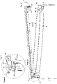
- An oven door 1 for closing a baking or roasting chamber of an oven comprises an outwardly directed front pane 3 and an inner pane 15 which adjoins the baking or roasting chamber.
- a door handle 5 is provided to open the door 1 .
- a left 7 and a right 9 door pillar are glued to the side edges of the windscreen 3 .
- the door is a door that can be rotated about a vertical axis, so that for this purpose door hinges 11 are arranged on the top and bottom of the left-hand door pillar 7 .
- the oven door 1 also has a door cover 13 which covers the front pane 3 and inner pane 15 at their upper edges. While figure 1 showing the door cover 13 installed is in figure 2 an arrangement of the door cover 13 reproduced as it is at the beginning of an installation process.
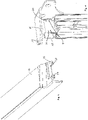
- the left door pillar comprises a metal hinge arm 17 which is covered by a door pillar cover 19.
- the hinge arm 17 is U-shaped in its central region, with only the central part of this U-shape remaining at least at its upper end.
- the door cover 13 is coupled in this end area of the hinge arm 17 .
- the end of the hinge arm has U-shaped recesses 21 on its side edges.
- FIG. 4 and 5 each shown an individual representation of the hinge arm end and the associated end of the door cover 13. Like in particular figure 5 As can be seen, a mandrel 23 and a projection 25 are arranged at the end of the door cover 13 and are accommodated by the two recesses 21 when the door cover 13 is installed.
- the door cover 13 is installed by initially threading the mandrel 23 and the projection 25 into the two recesses 21 .
- the door cover 13 is brought up to the hinge arm 17 at an acute angle of about 10 degrees in a horizontal movement parallel to the upper edges of the front pane 3 and inner pane 15 until the mandrel 23 and projection 25 are inserted into the recesses 21 .
- the mandrel 23 has an insertion bevel 27 on the underside. Following this insertion process, the door cover 13 is pressed down at its right end until it comes to rest on the top edges of the panes.
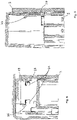
- the door cover 13 rotates about its bearing point 29 at its left end. Since the support point 29 is located between the mandrel 23 or projection 25 and the right-hand end of the door cover 13, the mandrel 23 and the projection 25 are simultaneously moved upwards while the right-hand end of the door cover 13 is being pressed down until their upper edges touch the respective upper edges of the recesses 21 concerns come.
- mandrel 23 and projection 25 rest against the upper edges 31 of the recesses 21 without play, with the upper edges 31 of the recesses 21 advantageously exerting pressure on the mandrel 23 and projection 25 so that they are under tension.
- a means 33 is provided in the form of a snap hook, which engages in a rear handle 35 on the right door pillar 9 .
- the door cover 13 is securely fastened to the oven door 1 with no play.
- a vertical tongue 37 is arranged on the door cover 13 at its right end as a stop part.
- This tongue 39 strikes a stop wall 43 (see in particular figure 7 ) and is delimited in its opposite direction by the windshield 3.
- the stop wall 43 is curved in the upper area in order to provide an insertion bevel.
- tongue 37 is also provided to limit movement in a direction parallel to the upper edge of front pane 3 and inner pane 15 .
- a stop edge 39 on the right-hand door pillar which corresponds to the side edge of tongue 37 .
- Another insertion bevel 41 is provided on the tongue 37 so that the tongue 37 does not get caught on the stop edge 39 when the door cover 13 is installed.
Landscapes
- Engineering & Computer Science (AREA)
- Chemical & Material Sciences (AREA)
- Combustion & Propulsion (AREA)
- Mechanical Engineering (AREA)
- General Engineering & Computer Science (AREA)
- Electric Ovens (AREA)
Description
- Die Erfindung betrifft eine Ofentüre. Ferner geht die Erfindung aus von einem Verfahren zum Befestigen eines Türabdeckteils an einer derartigen Ofentüre nach dem Oberbegriff des Anspruchs 10.
- Zum Verschließen der Ofenmuffel eines Back- und Bratofens werden in einer frontseitigen Anordnung Ofentüren eingesetzt. Diese sind üblicherweise am Gerätegehäuse drehbar gelagert, wobei bei einer Vielzahl von Back- und Bratöfen eine Lagerung an der Unterkante der Ofentüre bekannt ist, sodass sich beim Öffnen der Ofentüre eine Schwenkbewegung einstellt und diese von einer vertikalen Anordnung im Schließzustand in eine horizontale Anordnung im geöffneten Zustand übergeht. Es sind aber auch Back- und Bratöfen bekannt, bei denen das Türscharnier im Bereich einer Seitenkante der Ofentüre angeordnet ist, sodass die Türe beim Öffnen und Schließen eine Drehbewegung um eine horizontale Achse ausführt. Solche Ofentüren mit einem seitlichen Scharnier kommen insbesondere bei so genannten Doppelbratöfen zum Einsatz, also solchen Geräten, die zwei von einander getrennte und übereinander angeordnete Ofenmuffeln umfassen.
- Solche Ofentüren weisen in der Regel eine senkrecht angeordnete Türplatte auf, wobei hierfür insbesondere ein Türglas zum Einsatz kommt. Diese Türplatte bzw. dieses Türglas weist regelmäßig zwei vertikal angeordnete Türrahmen- oder Türsäulenteile auf, welche an die Türplatte in deren rechten und linken Seitenbereichen oder -kanten, insbesondere im Wege einer Klebeverbindung, angeordnet sind. Schließlich ist es noch bekannt, ein Türabdeckungsteil vorzusehen, welches wenigstens die Türplatte an deren Oberkante, insbesondere aber auch die oberen Stirnseiten der vertikal angeordneten Türrahmen- oder Türsäulenteile, von oben abdeckt.
- Eine derartige Ofentüre ist insbesondere aus der
EP 0 811 806 B2 bekannt. Dieses Dokument offenbart eine Ofentüre der vorgenannten Art, wobei darin das Türabdeckungsteil in einteiliger Ausführung mit einem Betätigungshandgriff ausgestaltet ist und dieses Kombinationsteil von oben auf die Türplatte und die Türrahmenteile bzw. Türsäulenteile aufgesteckt und mit diesen entweder verschraubt oder verrastet wird. - Insbesondere im Falle der vorgenannten Doppelbacköfen mit einer untenliegenden Muffel, die von einer seitlich gelagerten Türe verschlossen wird, ist jedoch ein derartiger Montageschritt senkrecht von oben wegen der seitlichen Anlenkung nicht durchführbar.
- Des Weiteren offenbart
EP 1 867 927 A2 eine Ofentüre mit einem Türabdeckungsteil, wobei das Türabdeckungsteil mittels einer Schnappverbindung an einem Türrahmenteil bzw. Türsäulenteil befestigt wird. - Es ist daher eine Aufgabe der Erfindung, eine Ofentüre gemäß dem Oberbegriff des Anspruchs 1, welche ein Türabdeckteil umfasst, sowie ein Verfahren nach dem Oberbegriff des Anspruchs 10 anzugeben, welche einen Ein- und Ausbau eines Türabdeckteiles in eine Ofentüre ermöglichen, ohne dass die Ofentüre hierzu ausgebaut werden muss, unabhängig davon, ob es sich um eine unten oder seitlich angelenkte Türe handelt. Die Lösung dieser Aufgabe gemäß der Ofentüre erfolgt erfindungsgemäß dadurch, dass das Türabdeckungsteil einen Dorn oder Vorsprung umfasst, der an einem ersten Seitenbereich des Türabdeckteiles angeordnet ist, wobei dieser Dorn oder Vorsprung derart ausgebildet ist, dass er in eine entsprechende Aussparung, welche an dem ersten Türrahmenteil oder Türsäulenteil angeordnet ist, eingreifen kann. Im Rahmen der Erfindung ist weiterhin das Mittel zum Herstellen der Schnappverbindung in dem dem Dorn oder Vorsprung abgewandten Seitenbereich des Türabdeckteiles vorgesehen, wobei dieses Mittel derart ausgestaltet ist, dass es in eine Aussparung am zweiten Türrahmenteil oder Türsäulenteil im Wege einer Schnappverbindung eingreift. Auf diese Weise ist ein Türabdeckteil geschaffen, das in eine beliebige Ofentüre eingebaut werden kann, unabhängig davon, ob es sich um eine um eine horizontale Achse schwenkbare Türe oder um eine um eine vertikale Achse schwenkbare Türe handelt. Zum Ein- und Ausbauen des Türabdeckteiles kann die Ofentüre dabei auch im am Gerät angebauten Zustand sein.
- Bei einer an einer Seitenkante angelenkten Ofentüre ist der Scharnierbereich für einen Einbau des Türabdeckteils von oben nicht direkt zugänglich. In diesem Fall ist es günstig, den Dorn bzw. den Vorsprung erfindungsgemäß mittels einer Horizontalverschiebung entlang der Oberkante der Türplatte in die Aussparung einzuschieben, wobei das Türabdeckteil in einem spitzen Winkel zur Türplattenoberkante angesetzt wird.
- Um ein Einführen des Dornes bzw. Stiftes in die Aussparung des Türabdeckteils im spitzen Winkel zur Türplattenoberkante zu ermöglichen, weist der Dorn bzw. Vorsprung eine Einführschräge oder- spitze auf. Hierbei kann es sich auch um eine schräg angesetzte Abflachung im unteren Bereich des Dornes bzw. Vorsprungs handeln.
- Das Schnappmittel, das am Endbereich des Türabdeckteiles angeordnet ist, welcher dem Endbereich mit dem Dorn bzw. Vorsprung gegenüber liegt, ist vorzugsweise mit dem Türabdeckteil-Endbereich, insbesondere mit einer dort befindlichen Seitenwand, starr verbunden. Um das Einschnappen mit einem am zweiten Türrahmen- oder Türsäulenteil vorgesehenen Hintergriff zu erleichtern, ist es günstig, wenn das Schnappmittel und/oder die Seitenwand derart flexibel ausgestaltet ist bzw. sind, dass das Schnappmittel und/oder die Seitenwand beim Einschnappen aus der Ruheposition ausweichen kann bzw. können. Vorzugsweise ist jedoch die flexiblere Ausgestaltung auf die Seitenwand gerichtet. In diesem Fall ist nämlich ein leichter Ausbau des Türabdeckteiles, z. B. für eine bessere Reinigung desselben, dadurch ermöglicht, dass durch einen manuellen Druck auf die Seitenwand das Schnappmittel gegenüber der Aussparung am Türrahmen- oder Türsäulenteil außer Eingriff gebracht werden kann. Das starr mit der Seitenwand des Türabdeckteiles in Verbindung stehende Schnappmittel folgt in diesem Fall der dem manuellen Druck folgenden Ausweichbewegung, sodass das Schnappmittel, insbesondere ein Schnapphaken, aus der Aussparung austritt.
- Gemäß der Erfindung ist im ersten Seitenbereich des Türabdeckteiles unterseitig ein Auflagerpunkt vorgesehen. Dieser Auflagerpunkt wirkt während des Einbauvorganges mit dem Türrahmen- oder Türsäulenteil derart zusammen, das der Dorn bzw. Vorsprung beim Niederdrücken des Seitenbereiches, an dem sich das Schnappmittel befindet, nach dem Prinzip einer Wippe nach oben bewegt wird, und am Ende des Einbauvorganges, d. h. also im eingebauten Zustand, stützt sich die Oberseite des Dorns bzw. Vorsprung an einer Oberkante der Aussparung, in die der Dorn bzw. Vorsprung eingeführt ist, ab. Der Dorn bzw. Vorsprung befindet sich somit im eingebauten Zustand unter einer Spannung, verursacht durch das Zusammenwirken von einerseits Aussparung und Dorn bzw. Vorsprung an einem Ende sowie eingerastetes Schnappmittel am anderen Ende, welche beide das Türabdeckteil nach unten halten, und andererseits dem Auflagerpunkt, der an dieser Stelle eine Kraftkomponente nach oben einbringt. Aufgrund dieser Vorspannung ist sichergestellt, dass das Türabdeckteil spielfrei an der Ofentüre angekoppelt ist, sodass dieses Teil im Gebrauch des Ofens nicht klappert.
- In Richtung parallel zur Oberkante der Türplatte ist das Türabdeckteil insbesondere durch das eingerastete Schnappmittel und durch eine Positionierzunge, die sich an einer Anschlagwand oder -kante am zweiten Türrahmen- bzw. Türsäulenteil abstützt, in Position gehalten. In Richtung parallel zur Türplatte kann es, wie vorstehend bereits beschrieben, durch den an der Oberkante der Aussparung sich abstützenden Dorn bzw. Vorsprung und das eingerastete Schnappmittel fixiert sein. Schließlich kann noch vorgesehen sein, dass das Türabdeckteil in Richtung senkrecht zur Oberkante der Türplatte und senkrecht zur Oberfläche der Türplatte durch den in die Aussparung eingreifenden Dorn bzw. Vorsprung und die sich an einer am zweiten Türrahmen- bzw. Türsäulenteil angeordneten zweiten Anschlagwand oder -kante abstützende Positionierzunge positioniert ist. In Realisierung aller vorgenannten Positioniermaßnahmen ist das Türabdeckteil in allen drei Freiheitsgraden eingeschränkt und somit sicher mit der Ofentüre verbunden.
- Die Lösung der vorstehenden Aufgabe gemäß dem Verfahren erfolgt erfindungsgemäß dadurch, dass ein an einem ersten Seitenbereich des Türabdeckteils angeordneter Dorn oder Vorsprung in eine am ersten vertikalen Türrahmen- bzw. Türsäulenteil angeordnete Aussparung durch Parallelverschiebung gegenüber der Türplattenoberkante eingeführt wird, wobei das Türabdeckteil unter einem spitzen Winkel zur Türplattenoberkante ausgerichtet und an der Aussparung angesetzt wird, sowie dadurch, dass das Türabdeckteil im Anschluss an das Einführen des Dornes bzw. Vorsprungs durch eine Drehbewegung um einen Auflagerpunkt im Bereich des ersten Endabschnitts des Türabdeckteils unter Verkleinerung des spitzen Winkels abgesenkt und schließlich mit Hilfe von Schnappmitteln, die am zweiten, dem Dorn oder Vorsprung abgewandten Endbereich des Türabdeckteils angeordnet sind, mit dem zweiten vertikalen Türrahmen- bzw. Türsäulenteil verschnappt wird. Das Einführen des Dorns bzw. Vorsprungs in die Aussparung erfolgt vorzugsweise unter einem Winkel in einem Bereich von ca. 5 - ca. 50 Grad zwischen Türplattenoberkante und Türabdeckteil.
- Zur spielfreien Halterung des Türabdeckteils wird der in die Aussparung eingeführte Dorn bzw. Vorsprung während des Einbauvorgangs mit abschließendem Einschnappen vorzugsweise nach oben bewegt, bedingt durch die Drehbewegung um den Auflagerpunkt, und er stützt sich im eingebauten Zustands des Türabdeckteils gegen die Oberkante der Aussparung ab.
- Der Ausbau des Türabdeckteils kann durch anfängliches außer Eingriff bringen des Schnappmittels und nachfolgendes Durchführen der Ausbaubewegung in umgekehrter Reihenfolge zu Einbaubewegung geschehen. Um die Schnappverbindung ohne irgendwelche Hilfsmittel zu lösen, kann vorgesehen sein, dass das Schnappmittel mit einer Seitenwand des Türabdeckteils starr verbunden ist und durch manuellen Druck auf die Seitenwand außer Eingriff gebracht werden kann.
- Die Erfindung wird im Folgenden anhand der Zeichnungen eines Ausführungsbeispiels näher erläutert. Dabei zeigen:
- Figur 1
- einen oberen Ausschnitt einer Ofentüre mit einer Türabdeckung
- Figur 2
- den Ofentürausschnitt gemäß
Figur 1 mit abgehobener Türabdeckung, - Figur 3
- eine Detailansicht A von
Figur 2 , - Figur 4, Figur 5
- die getrennten Einzelteile aus
Figur 3 , - Figur 6
- die Detailansicht gemäß
Figur 3 in der Seitenansicht mit einer Türabdeckung im Einbauzustand, - Figur 7
- eine stirnseitige Ansicht der Detailansicht von
Figur 6 - Figur 8
- eine Detailansicht des rechten Endabschnitts der Türabdeckung gemäß
Figur 1 , in Seitenansicht; und - Figur 9
- die Detailansicht gemäß
Figur 8 in Seitenansicht IX - IX. - Eine Ofentüre 1 zum Verschließen eines Back- bzw. Bratraumes eines Ofens umfasst eine nach außen gerichtete Frontscheibe 3 und eine Innenscheibe 15, die an den Back- bzw. Bratraum angrenzt. Zum Öffnen der Türe 1 ist ein Türgriff 5 vorgesehen. An die Seitenkanten der Frontscheibe 3 sind eine linke 7 und eine rechte 9 Türsäule angeklebt. Bei der Tür handelt es sich um eine um eine vertikale Achse drehbare Türe, sodass zu diesem Zweck an der linken Türsäule 7 oberseitig und unterseitig Türscharniere 11 angeordnet sind.
- Die Ofentüre 1 weist ferner eine Türabdeckung 13 auf, die Frontscheibe 3 und Innenscheibe 15 an deren Oberkanten abdeckt. Während
Figur 1 die Türabdeckung 13 im eingebauten Zustand zeigt, ist inFigur 2 eine Anordnung der Türabdeckung 13 wiedergegeben, wie sie sich zu Beginn eines Einbauvorganges darstellt. - Wie insbesondere in der Detailansicht gemäß
Figur 3 zu erkennen ist, umfasst die linke Türsäule einen metallenen Scharnierarm 17, der von einer Türsäulenabdeckung 19 bedeckt ist. Der Scharnierarm 17 ist in seinem Mittelbereich U-förmig ausgebildet, wobei wenigstens an seinem oberen Ende von dieser U-form lediglich der Mittelteil stehen bleibt. In diesem Endbereich des Scharnierarmes 17 wird die Türabdeckung 13 angekoppelt. Zu diesem Zweck weist das Scharnierarmende an seinen Seitenkanten U-förmige Aussparungen 21 auf. - Zur besseren Darstellung ist gemäß
Figuren 4 und 5 je eine Einzeldarstellung des Scharnierarmendes sowie das dazugehörige Ende der Türabdeckung 13 gezeigt. Wie insbesondere ausFigur 5 ersichtlich sind am Ende der Türabdeckung 13 ein Dorn 23 sowie ein Vorsprung 25 angeordnet, welche im eingebauten Zustand der Türabdeckung 13 von den beiden Aussparungen 21 aufgenommen werden. - Wie aus
Figur 2 ersichtlich erfolgt der Einbau der Türabdeckung 13 dadurch, dass anfänglich der Dorn 23 und der Vorsprung 25 in die beiden Aussparungen 21 eingefädelt werden. Hierzu wird die Türabdeckung 13 unter einem spitzen Winkel von ca. 10 Grad an den Scharnierarm 17 in einer Horizontalbewegung parallel zu den Oberkanten von Frontscheibe 3 und Innenscheibe 15 herangeführt bis Dorn 23 und Vorsprung 25 in die Aussparungen 21 eingeführt sind. Für ein leichtes Einführen des Dornes 23 in der Schrägstellung der Türabdeckung 13 weist Dorn 23 unterseitig eine Einführschräge 27 auf. Im Anschluss an diesen Einführvorgang wird die Türabdeckung 13 an ihrem rechten Ende heruntergedrückt bis sie auf den Scheibenoberkanten zum Aufliegen kommt. Während des Niederdrückens vollzieht die Türabdeckung 13 um ihren Auflagerpunkt 29 an ihrem linken Ende eine Drehbewegung. Da der Auflagerpunkt 29 sich zwischen Dorn 23 bzw. Vorsprung 25 und rechtem Ende der Türabdeckung 13 befindet, werden gleichzeitig während des Niederdrückens des rechten Endes der Türabdeckung 13 Dorn 23 und Vorsprung 25 nach oben bewegt bis deren Oberkanten an den jeweiligen Oberkanten der Aussparungen 21 zum Anliegen kommen. Im eingebauten Zustand liegen Dorn 23 und Vorsprung 25 an den Oberkanten 31 der Aussparungen 21 spielfrei an, wobei günstigenfalls von den Oberkanten 31 der Aussparungen 21 auf Dorn 23 und Vorsprung 25 ein Druck ausgeübt wird, sodass diese unter Spannung stehen. Zur Fixierung der Türabdeckung 13 an der rechten Seite ist ein Mittel 33 in Form eines Schnapphakens vorgesehen, der in einem Hintergriff 35 an der rechten Türsäule 9 zum Eingriff kommt. Sobald die Schnappverbindung hergestellt ist, ist die Türabdeckung 13 sicher und spielfrei an der Ofentüre 1 befestigt. Damit die Türabdeckung im Bereich der rechten Türsäule 9 keinen Freiraum in horizontaler Richtung senkrecht zur Oberkante der Scheiben 3, 15 hat, ist an die Türabdeckung 13 an seinem rechten Ende eine senkrechte Zunge 37 als Anschlagteil angeordnet. Diese Zunge 39 schlägt an eine Anschlagwand 43 (vergleiche insbesondereFigur 7 ) an und wird in ihrer entgegengesetzten Richtung von der Frontscheibe 3 begrenzt. Für ein erleichtertes Einbauen ist die Anschlagswand 43 im oberen Bereich bogenförmig ausgestaltet um eine Einführschräge zu liefern. - Schließlich ist Zunge 37 auch für eine Bewegungsbegrenzung in Richtung parallel zur Oberkante von Frontscheibe 3 und Innenscheibe 15 vorgesehen. Hierzu befindet sich eine Anschlagkante 39 an der rechten Türsäule, welche mit der Seitenkante der Zunge 37 korrespondiert. Damit beim Einbau der Türabdeckung 13 die Zunge 37 nicht an der Anschlagkante 39 hängen bleibt, ist eine weitere Einführschräge 41 an der Zunge 37 vorgesehen.
- Für einen einfachen Ausbau der Türabdeckung 13 muss lediglich auf ihre mit einer Riffelung 45 versehende Seitenwand ein manueller Druck ausgeübt werden. Dadurch löst sich die Schnappverbindung und das Mittel 33 in Form eines Schnapphakens kommt außer Eingriff. In umgekehrter Reihenfolge zur Einbaubewegung kann dann der Ausbau erfolgen.
Claims (14)
- Ofentüre (1), insbesondere mit seitlich angeordnetem Türscharnier (11), umfassend(a) wenigstens eine in einem geschlossenen Zustand der Ofentüre (1) senkrecht angeordnete Türplatte (3, 15), insbesondere Türglas,(b) ein erstes und ein zweites im geschlossenen Zustand der Ofentüre (1) vertikal angeordnetes Türrahmenteil oder Türsäulenteil (7, 9), welche an der Türplatte (3) in deren im geschlossenen Zustand der Ofentüre (1) rechten und linken Seitenbereichen oder -kanten angeordnet sind; und(c) ein Türabdeckteil (13), welches wenigstens die Türplatte (3, 15) im geschlossenen Zustand der Ofentüre (1) von oben an deren Oberkante abdeckt und ein Mittel (33) zum Herstellen einer Schnappverbindung umfasst,
wobei das Türabdeckteil (13) weiterhin folgendes umfasst:(d) einen Dorn (23) oder Vorsprung (25), angeordnet an einem ersten Seitenbereich des Türabdeckteiles (13), wobei dieser Dorn (23) oder Vorsprung (25) derart ausgebildet ist, dass er durch Parallelverschiebung gegenüber der Türplattenoberkante bei unter einem spitzen Winkel zur Türplattenoberkante ausgerichtetem Türabdeckteil (13) in eine entsprechende Aussparung (21), welche an dem ersten Türrahmenteil oder Türsäulenteil (7) angeordnet ist, einführbar ist und in diese eingreifen kann; wobei(e) das Mittel (33) zum Herstellen der Schnappverbindung in einem dem Dorn (23) oder Vorsprung (25) abgewandten Seitenbereich des Türabdeckteiles (13) ausgebildet ist, und wobei dieses Mittel (33) derart ausgestaltet ist, dass es nach dem Einführen des Dorns (23) bzw. Vorsprungs (25) in die Aussparung (21) und einer Dreh- oder Kippbewegung des Türabdeckteils (13) um einen Auflagerpunkt (29) im ersten Seitenbereich des Türabdeckteils (13) in eine Aussparung oder einen Hintergriff (35) am zweiten Türrahmenteil oder Türsäulenteil (9) im Wege einer Schnappverbindung eingreifen kann. - Ofentüre (1) nach Anspruch 1, dadurch gekennzeichnet, dass der Dorn (23) bzw. Vorsprung (25) eine Einführschräge (27) oder -spitze aufweist, um sein Einführen in die Aussparung des Türrahmenteils (7) in einem spitzen Winkel zur Türplattenoberkante zu ermöglichen.
- Ofentüre (1) gemäß Anspruch 1 oder 2, dadurch gekennzeichnet, dass das Schnappmittel (33) mit einer Seitenwand (45) des Türabdeckteils (13) starr verbunden ist.
- Ofentüre (1) nach Anspruch 3, dadurch gekennzeichnet, dass das Schnappmittel (33) und/oder die Seitenwand (45) derart flexibel ausgestaltet ist bzw. sind, dass Schnappmittel (33) und/oder Seitenwand (45) beim Einschnappen aus der Ruheposition ausweichen kann bzw. können.
- Ofentüre (1) nach Anspruch 3 oder 4, dadurch gekennzeichnet, dass das Schnappmittel (33) für ein Entnehmen des Türabdeckteiles (13) durch einen manuellen Druck auf die Seitenwand (45) außer Eingriff bringbar ist.
- Ofentüre (1) nach einem der Ansprüche 1 bis 5, dadurch gekennzeichnet, dass der Auflagerpunkt (29) im ersten Seitenbereich des Türabdeckteils (13) unterseitig vorgesehen ist, und dass der Auflagerpunkt (29) mit dem Türrahmen- oder Türsäulenteil (7) derart zusammenwirkt, dass im Sinne einer Wippe während des Einbauvorgangs beim Niederdrücken des zweiten Seitenbereiches der Dorn (23) bzw. Vorsprung (25) nach oben bewegt wird und sich im eingebauten Zustand gegen eine Oberkante (31) der Aussparung (21) abstützt.
- Ofentüre (1) nach einem der Ansprüche 1 bis 6, dadurch gekennzeichnet, dass das eingebaute Türabdeckteil (13) in Richtung parallel zur Oberkante der Türplatte (3, 15) durch das eingerastete Schnappmittel (33) und durch eine Positionierzunge (37), die sich an einer Anschlagwand oder -kante (39) am zweiten Türrahmenteil bzw. Türsäulenteil (9) abstützt, in Position gehalten ist.
- Ofentüre (1) nach einem der Ansprüche 1 bis 7, dadurch gekennzeichnet, dass das eingebaute Türabdeckteil (13) in Richtung parallel zur Oberfläche der Türplatte (3, 15) durch den sich an der Oberkante (31) der Aussparung (21) abstützenden Dorn (23) bzw. Vorsprung (25) und das in eine Rastverbindung gebrachte Schnappmittel (33) in Position gehalten ist.
- Ofentüre (1) nach einem der Ansprüche 1 bis 8, dadurch gekennzeichnet, dass das eingebaute Türabdeckteil (13) in Richtung senkrecht zur Oberkante der Türplatte (3, 15) und senkrecht zur Oberfläche der Türplatte (3, 15) durch den in die Aussparung (21) eingreifenden Dorn (23) bzw. Vorsprung (25) und die sich an einer am zweiten Türrahmenteil bzw. Türsäulenteil (9) angeordneten zweiten Anschlagwand (43) oder -kante abstützende Positionierzunge (37) in Position gehalten ist.
- Verfahren zum Befestigen eines Türabdeckteils (13) einer Ofentüre (1) nach einem der vorhergehenden Ansprüche an einem ersten und einem zweiten in einem geschlossenen Zustand der Ofentüre (1) vertikalen Türrahmenteil oder Türsäulenteil (7, 9) der Ofentüre (1) zur Abdeckung einer im geschlossenen Zustand der Ofentüre (1) vertikal ausgerichteten Türplatte (3, 15) der Ofentüre (1) auf deren Oberseite, dadurch gekennzeichnet, dass ein Dorn (23) oder Vorsprung (25), welcher an einem ersten Seitenbereich des Türabdeckteils (13) angeordnet ist, bei unter einem spitzen Winkel zur Türplattenoberkante ausgerichtetem Türabdeckteil (13) in eine am ersten vertikalen Türrahmenteil bzw. Türsäulenteil (7) angeordnete Aussparung (21) durch Parallelverschiebung gegenüber der Türplattenoberkante eingeführt wird und dass das Türabdeckteil (13) danach durch eine Dreh- oder Kippbewegung um einen Auflagerpunkt (29) im Bereich des ersten Endabschnitts des Türabdeckteils (13) abgesenkt und abschließend mit Hilfe von Schnappmitteln (33), die am zweiten, dem Dorn (23) oder Vorsprung (25) abgewandten Endbereich des Türabdeckteils (13) angeordnet sind, mit dem zweiten vertikalen Türrahmenteil bzw. Türsäulenteil (9) verschnappt wird.
- Verfahren nach Anspruch 10, dadurch gekennzeichnet, dass das Einführen des Dorns (23) bzw. Vorsprungs (25) in die Aussparung (21) unter einem Winkel in einem Bereich von ca. 5 bis ca. 50 Grad zwischen Türplattenoberkante und Türabdeckteil (13) erfolgt.
- Verfahren nach Anspruch 10 oder 11, dadurch gekennzeichnet, dass während des Einschnappens der in die Aussparung (21) eingeführte Dorn (23) bzw. Vorsprung (25) nach oben bewegt wird und sich im eingebauten Zustand des Türabdeckteils (13) gegen die Oberkante (31) der Aussparung (21) abstützt.
- Verfahren nach einem der Ansprüche 10 bis 12, dadurch gekennzeichnet, dass ein Ausbau des Türabdeckteiles (13) dadurch erfolgt, dass zunächst das Schnappmittel (33) außer Eingriff gebracht wird und die Ausbaubewegung nachfolgend in umgekehrter Reihenfolge zur Einbaubewegung durchgeführt wird.
- Verfahren nach Anspruch 13, dadurch gekennzeichnet, dass das Schnappmittel (33) mit einer Seitenwand (45) des Türabdeckteils (13) starr verbunden ist und durch Druck auf die Seitenwand (45) außer Eingriff gebracht wird.
Applications Claiming Priority (2)
| Application Number | Priority Date | Filing Date | Title |
|---|---|---|---|
| DE102010013903A DE102010013903A1 (de) | 2010-04-01 | 2010-04-01 | Ofentüre, sowie Verfahren zum Befestigen eines Türabdeckteils |
| PCT/EP2011/001588 WO2011120678A1 (de) | 2010-04-01 | 2011-03-30 | Ofentüre, sowie verfahren zum befestigen eines türabdeckteils |
Publications (3)
| Publication Number | Publication Date |
|---|---|
| EP2553343A1 EP2553343A1 (de) | 2013-02-06 |
| EP2553343B1 EP2553343B1 (de) | 2018-05-30 |
| EP2553343B2 true EP2553343B2 (de) | 2022-03-30 |
Family
ID=44279759
Family Applications (1)
| Application Number | Title | Priority Date | Filing Date |
|---|---|---|---|
| EP11711785.3A Active EP2553343B2 (de) | 2010-04-01 | 2011-03-30 | Ofentüre, sowie verfahren zum befestigen eines türabdeckteils an einer derartigen ofentüre |
Country Status (3)
| Country | Link |
|---|---|
| EP (1) | EP2553343B2 (de) |
| DE (1) | DE102010013903A1 (de) |
| WO (1) | WO2011120678A1 (de) |
Families Citing this family (7)
| Publication number | Priority date | Publication date | Assignee | Title |
|---|---|---|---|---|
| DE102012203009A1 (de) * | 2012-02-28 | 2013-08-29 | BSH Bosch und Siemens Hausgeräte GmbH | Trägerteil für eine Türscheibe einer Backofentür sowie Tür für ein Haushaltsgerät zum Zubereiten von Lebensmitteln mit einem derartigen Trägerteil |
| DE102012213126B4 (de) * | 2012-07-26 | 2022-11-10 | BSH Hausgeräte GmbH | Tür für ein Haushaltsgerät mit einem Rastelement und einem Vorspannelement sowie Backofen mit einer derartigen Tür |
| DE102012217355A1 (de) * | 2012-09-26 | 2014-03-27 | BSH Bosch und Siemens Hausgeräte GmbH | Tür für ein Haushaltsgerät und Haushaltsgerät zum Zubereiten von Lebensmitteln mit einer Tür |
| ITPR20120085A1 (it) | 2012-12-20 | 2014-06-21 | Indesit Co Spa | Forno per la cottura di pietanze. |
| DE102016224743A1 (de) | 2016-12-12 | 2018-06-14 | BSH Hausgeräte GmbH | Haushaltsgargerät |
| DE102018221069A1 (de) * | 2018-12-05 | 2020-06-10 | BSH Hausgeräte GmbH | Tür für ein Haushaltsgerät mit mechanisch gekippter Blende, sowie Haushaltsgerät und Verfahren zur Montage einer Blende für ein Scheibenpaket der Tür |
| KR20240041482A (ko) * | 2022-09-23 | 2024-04-01 | 엘지전자 주식회사 | 조리기기 |
Citations (7)
| Publication number | Priority date | Publication date | Assignee | Title |
|---|---|---|---|---|
| EP1030116A2 (de) † | 1999-02-17 | 2000-08-23 | Imperial-Werke GmbH & Co. | Backofen |
| DE10163150C2 (de) † | 2000-12-22 | 2003-10-30 | Miele & Cie | Gerätetür, vorzugsweise für einen Backofen |
| EP1122500B1 (de) † | 2000-02-03 | 2006-03-29 | MIWE Michael Wenz GmbH | Backofen mit Dunstfang |
| US20060265960A1 (en) † | 2005-05-27 | 2006-11-30 | Maytag Corporation | Refrigerator door with end cap |
| EP1867927A2 (de) † | 2006-06-13 | 2007-12-19 | Electrolux Home Products Corporation N.V. | Tür eines Garofens, insbesondere eines Haushaltsgarofens, sowie Verfahren zur Herstellung |
| EP2090832A1 (de) † | 2008-02-15 | 2009-08-19 | Electrolux Home Products Corporation N.V. | Türensystem zur Schließung einer Zufuhrvorrichtung zum Garraum eines Backofens |
| EP1901006B1 (de) † | 2006-09-08 | 2017-12-13 | BSH Hausgeräte GmbH | Backofen |
Family Cites Families (3)
| Publication number | Priority date | Publication date | Assignee | Title |
|---|---|---|---|---|
| DE3238441A1 (de) * | 1982-10-16 | 1984-04-19 | Licentia Patent-Verwaltungs-Gmbh, 6000 Frankfurt | Back- und bratofen |
| DE59702655D1 (de) | 1996-06-05 | 2000-12-28 | Aeg Hausgeraete Gmbh | Tür zum Verschliessen der Ofenmuffel eines Back- und Bratofens |
| DE102005037020A1 (de) * | 2004-09-09 | 2006-03-16 | BSH Bosch und Siemens Hausgeräte GmbH | Vorrichtung mit einer Haushaltsgerätetürträgereinheit |
-
2010
- 2010-04-01 DE DE102010013903A patent/DE102010013903A1/de not_active Withdrawn
-
2011
- 2011-03-30 EP EP11711785.3A patent/EP2553343B2/de active Active
- 2011-03-30 WO PCT/EP2011/001588 patent/WO2011120678A1/de not_active Ceased
Patent Citations (7)
| Publication number | Priority date | Publication date | Assignee | Title |
|---|---|---|---|---|
| EP1030116A2 (de) † | 1999-02-17 | 2000-08-23 | Imperial-Werke GmbH & Co. | Backofen |
| EP1122500B1 (de) † | 2000-02-03 | 2006-03-29 | MIWE Michael Wenz GmbH | Backofen mit Dunstfang |
| DE10163150C2 (de) † | 2000-12-22 | 2003-10-30 | Miele & Cie | Gerätetür, vorzugsweise für einen Backofen |
| US20060265960A1 (en) † | 2005-05-27 | 2006-11-30 | Maytag Corporation | Refrigerator door with end cap |
| EP1867927A2 (de) † | 2006-06-13 | 2007-12-19 | Electrolux Home Products Corporation N.V. | Tür eines Garofens, insbesondere eines Haushaltsgarofens, sowie Verfahren zur Herstellung |
| EP1901006B1 (de) † | 2006-09-08 | 2017-12-13 | BSH Hausgeräte GmbH | Backofen |
| EP2090832A1 (de) † | 2008-02-15 | 2009-08-19 | Electrolux Home Products Corporation N.V. | Türensystem zur Schließung einer Zufuhrvorrichtung zum Garraum eines Backofens |
Also Published As
| Publication number | Publication date |
|---|---|
| DE102010013903A1 (de) | 2011-10-06 |
| EP2553343A1 (de) | 2013-02-06 |
| EP2553343B1 (de) | 2018-05-30 |
| WO2011120678A1 (de) | 2011-10-06 |
Similar Documents
| Publication | Publication Date | Title |
|---|---|---|
| EP2553343B2 (de) | Ofentüre, sowie verfahren zum befestigen eines türabdeckteils an einer derartigen ofentüre | |
| DE112013007355B4 (de) | Scharnier für eine Falttür | |
| EP2379794A1 (de) | Haushaltsgerät, insbesondere geschirrspülmaschine | |
| AT513033B1 (de) | Montageplatte für Möbelstellantriebe | |
| DE10352236A1 (de) | Kraftfahrzeugtür und Trägerplatte einer Kraftfahrzeugtür | |
| DE10163150A1 (de) | Gerätetür, vorzugsweise für einen Backofen | |
| EP3865777B1 (de) | Dunstabzugsvorrichtung mit frontklappe | |
| EP3676468B1 (de) | Schliesseinrichtung für einen schaltschrank und ein entsprechender schaltschrank | |
| EP4185810A1 (de) | Gargerät mit falttür mit versetzten scharnieren | |
| EP2949842B1 (de) | Türgriffanordnung für ein kraftfahrzeug | |
| DE102008041494B4 (de) | Hausgerät, insbesondere Backofen | |
| EP2014847B2 (de) | Revisionsabdeckung | |
| EP2741015A2 (de) | Tür für ein Haushaltsgerät mit einem plattenartigen Greifteil und einem Greifteilöffner, Haushaltsgerät mit einer derartigen Tür sowie Verfahren zum Öffnen einer Tür eines Haushaltsgeräts | |
| WO2020169245A1 (de) | Fenster für ein fahrzeug oder einen container mit einem verriegelungsmechanismus | |
| EP2853675B1 (de) | Tür für Rauchschutzzwecke | |
| EP1548367B1 (de) | Vorrichtung zum Verschliessen der Zugangsöffnung eines Innenraums eines Haushaltsgeräts | |
| EP3688260A1 (de) | IN DER KIPPSTELLUNG VERRASTBARER UND DENNOCH BEIM SCHIEB-SCHLIEßEN LEICHT BEWEGBARER BESCHLAG FÜR EIN FENSTER ODER EINE TÜR | |
| DE102005059274B4 (de) | Verblendungsvorrichtung für Fahrzeugdachsysteme mit öffnungsfähigem Deckel | |
| EP2365165B1 (de) | Beschlag und Duschabtrennung | |
| DE3205417C2 (de) | Dachfenster für Kraftfahrzeuge | |
| EP1889333A1 (de) | Steckscharnier | |
| DE102010029331B4 (de) | Gargerätetür | |
| CH695353A5 (de) | Insektenschutzgitter für ein Fenster oder eine Tür. | |
| EP2740871A2 (de) | Vorrichtung für ein Haushaltsgerät mit einem Scharnier und einer Koppeleinrichtung sowie Haushaltsgerät mit einer derartigen Vorrichtung | |
| EP3981942A1 (de) | Anordnung mit einer bodendichtung für eine tür, bei der zwischen einem türblatt und einer zarge ein zwischenraum vorgesehen ist, in dem eine drehachse des türblatts verläuft |
Legal Events
| Date | Code | Title | Description |
|---|---|---|---|
| PUAI | Public reference made under article 153(3) epc to a published international application that has entered the european phase |
Free format text: ORIGINAL CODE: 0009012 |
|
| 17P | Request for examination filed |
Effective date: 20120926 |
|
| AK | Designated contracting states |
Kind code of ref document: A1 Designated state(s): AL AT BE BG CH CY CZ DE DK EE ES FI FR GB GR HR HU IE IS IT LI LT LU LV MC MK MT NL NO PL PT RO RS SE SI SK SM TR |
|
| DAX | Request for extension of the european patent (deleted) | ||
| 17Q | First examination report despatched |
Effective date: 20151222 |
|
| GRAP | Despatch of communication of intention to grant a patent |
Free format text: ORIGINAL CODE: EPIDOSNIGR1 |
|
| STAA | Information on the status of an ep patent application or granted ep patent |
Free format text: STATUS: GRANT OF PATENT IS INTENDED |
|
| INTG | Intention to grant announced |
Effective date: 20170912 |
|
| GRAJ | Information related to disapproval of communication of intention to grant by the applicant or resumption of examination proceedings by the epo deleted |
Free format text: ORIGINAL CODE: EPIDOSDIGR1 |
|
| STAA | Information on the status of an ep patent application or granted ep patent |
Free format text: STATUS: EXAMINATION IS IN PROGRESS |
|
| GRAP | Despatch of communication of intention to grant a patent |
Free format text: ORIGINAL CODE: EPIDOSNIGR1 |
|
| STAA | Information on the status of an ep patent application or granted ep patent |
Free format text: STATUS: GRANT OF PATENT IS INTENDED |
|
| INTC | Intention to grant announced (deleted) | ||
| INTG | Intention to grant announced |
Effective date: 20180118 |
|
| GRAS | Grant fee paid |
Free format text: ORIGINAL CODE: EPIDOSNIGR3 |
|
| GRAA | (expected) grant |
Free format text: ORIGINAL CODE: 0009210 |
|
| STAA | Information on the status of an ep patent application or granted ep patent |
Free format text: STATUS: THE PATENT HAS BEEN GRANTED |
|
| AK | Designated contracting states |
Kind code of ref document: B1 Designated state(s): AL AT BE BG CH CY CZ DE DK EE ES FI FR GB GR HR HU IE IS IT LI LT LU LV MC MK MT NL NO PL PT RO RS SE SI SK SM TR |
|
| REG | Reference to a national code |
Ref country code: GB Ref legal event code: FG4D Free format text: NOT ENGLISH |
|
| REG | Reference to a national code |
Ref country code: CH Ref legal event code: EP |
|
| REG | Reference to a national code |
Ref country code: AT Ref legal event code: REF Ref document number: 1003986 Country of ref document: AT Kind code of ref document: T Effective date: 20180615 |
|
| REG | Reference to a national code |
Ref country code: IE Ref legal event code: FG4D Free format text: LANGUAGE OF EP DOCUMENT: GERMAN |
|
| REG | Reference to a national code |
Ref country code: DE Ref legal event code: R096 Ref document number: 502011014243 Country of ref document: DE |
|
| REG | Reference to a national code |
Ref country code: RO Ref legal event code: EPE |
|
| REG | Reference to a national code |
Ref country code: NL Ref legal event code: MP Effective date: 20180530 |
|
| REG | Reference to a national code |
Ref country code: LT Ref legal event code: MG4D |
|
| PG25 | Lapsed in a contracting state [announced via postgrant information from national office to epo] |
Ref country code: SE Free format text: LAPSE BECAUSE OF FAILURE TO SUBMIT A TRANSLATION OF THE DESCRIPTION OR TO PAY THE FEE WITHIN THE PRESCRIBED TIME-LIMIT Effective date: 20180530 Ref country code: FI Free format text: LAPSE BECAUSE OF FAILURE TO SUBMIT A TRANSLATION OF THE DESCRIPTION OR TO PAY THE FEE WITHIN THE PRESCRIBED TIME-LIMIT Effective date: 20180530 Ref country code: BG Free format text: LAPSE BECAUSE OF FAILURE TO SUBMIT A TRANSLATION OF THE DESCRIPTION OR TO PAY THE FEE WITHIN THE PRESCRIBED TIME-LIMIT Effective date: 20180830 Ref country code: LT Free format text: LAPSE BECAUSE OF FAILURE TO SUBMIT A TRANSLATION OF THE DESCRIPTION OR TO PAY THE FEE WITHIN THE PRESCRIBED TIME-LIMIT Effective date: 20180530 Ref country code: CY Free format text: LAPSE BECAUSE OF FAILURE TO SUBMIT A TRANSLATION OF THE DESCRIPTION OR TO PAY THE FEE WITHIN THE PRESCRIBED TIME-LIMIT Effective date: 20180530 Ref country code: NO Free format text: LAPSE BECAUSE OF FAILURE TO SUBMIT A TRANSLATION OF THE DESCRIPTION OR TO PAY THE FEE WITHIN THE PRESCRIBED TIME-LIMIT Effective date: 20180830 Ref country code: ES Free format text: LAPSE BECAUSE OF FAILURE TO SUBMIT A TRANSLATION OF THE DESCRIPTION OR TO PAY THE FEE WITHIN THE PRESCRIBED TIME-LIMIT Effective date: 20180530 |
|
| PG25 | Lapsed in a contracting state [announced via postgrant information from national office to epo] |
Ref country code: GR Free format text: LAPSE BECAUSE OF FAILURE TO SUBMIT A TRANSLATION OF THE DESCRIPTION OR TO PAY THE FEE WITHIN THE PRESCRIBED TIME-LIMIT Effective date: 20180831 Ref country code: HR Free format text: LAPSE BECAUSE OF FAILURE TO SUBMIT A TRANSLATION OF THE DESCRIPTION OR TO PAY THE FEE WITHIN THE PRESCRIBED TIME-LIMIT Effective date: 20180530 Ref country code: LV Free format text: LAPSE BECAUSE OF FAILURE TO SUBMIT A TRANSLATION OF THE DESCRIPTION OR TO PAY THE FEE WITHIN THE PRESCRIBED TIME-LIMIT Effective date: 20180530 Ref country code: RS Free format text: LAPSE BECAUSE OF FAILURE TO SUBMIT A TRANSLATION OF THE DESCRIPTION OR TO PAY THE FEE WITHIN THE PRESCRIBED TIME-LIMIT Effective date: 20180530 |
|
| PG25 | Lapsed in a contracting state [announced via postgrant information from national office to epo] |
Ref country code: NL Free format text: LAPSE BECAUSE OF FAILURE TO SUBMIT A TRANSLATION OF THE DESCRIPTION OR TO PAY THE FEE WITHIN THE PRESCRIBED TIME-LIMIT Effective date: 20180530 |
|
| PG25 | Lapsed in a contracting state [announced via postgrant information from national office to epo] |
Ref country code: CZ Free format text: LAPSE BECAUSE OF FAILURE TO SUBMIT A TRANSLATION OF THE DESCRIPTION OR TO PAY THE FEE WITHIN THE PRESCRIBED TIME-LIMIT Effective date: 20180530 Ref country code: DK Free format text: LAPSE BECAUSE OF FAILURE TO SUBMIT A TRANSLATION OF THE DESCRIPTION OR TO PAY THE FEE WITHIN THE PRESCRIBED TIME-LIMIT Effective date: 20180530 Ref country code: EE Free format text: LAPSE BECAUSE OF FAILURE TO SUBMIT A TRANSLATION OF THE DESCRIPTION OR TO PAY THE FEE WITHIN THE PRESCRIBED TIME-LIMIT Effective date: 20180530 Ref country code: PL Free format text: LAPSE BECAUSE OF FAILURE TO SUBMIT A TRANSLATION OF THE DESCRIPTION OR TO PAY THE FEE WITHIN THE PRESCRIBED TIME-LIMIT Effective date: 20180530 Ref country code: SK Free format text: LAPSE BECAUSE OF FAILURE TO SUBMIT A TRANSLATION OF THE DESCRIPTION OR TO PAY THE FEE WITHIN THE PRESCRIBED TIME-LIMIT Effective date: 20180530 |
|
| REG | Reference to a national code |
Ref country code: DE Ref legal event code: R026 Ref document number: 502011014243 Country of ref document: DE |
|
| PLBI | Opposition filed |
Free format text: ORIGINAL CODE: 0009260 |
|
| PG25 | Lapsed in a contracting state [announced via postgrant information from national office to epo] |
Ref country code: IT Free format text: LAPSE BECAUSE OF FAILURE TO SUBMIT A TRANSLATION OF THE DESCRIPTION OR TO PAY THE FEE WITHIN THE PRESCRIBED TIME-LIMIT Effective date: 20180530 Ref country code: SM Free format text: LAPSE BECAUSE OF FAILURE TO SUBMIT A TRANSLATION OF THE DESCRIPTION OR TO PAY THE FEE WITHIN THE PRESCRIBED TIME-LIMIT Effective date: 20180530 |
|
| PLAX | Notice of opposition and request to file observation + time limit sent |
Free format text: ORIGINAL CODE: EPIDOSNOBS2 |
|
| 26 | Opposition filed |
Opponent name: BSH HAUSGERAETE GMBH Effective date: 20190208 |
|
| PG25 | Lapsed in a contracting state [announced via postgrant information from national office to epo] |
Ref country code: SI Free format text: LAPSE BECAUSE OF FAILURE TO SUBMIT A TRANSLATION OF THE DESCRIPTION OR TO PAY THE FEE WITHIN THE PRESCRIBED TIME-LIMIT Effective date: 20180530 |
|
| PLAF | Information modified related to communication of a notice of opposition and request to file observations + time limit |
Free format text: ORIGINAL CODE: EPIDOSCOBS2 |
|
| PLBB | Reply of patent proprietor to notice(s) of opposition received |
Free format text: ORIGINAL CODE: EPIDOSNOBS3 |
|
| REG | Reference to a national code |
Ref country code: DE Ref legal event code: R119 Ref document number: 502011014243 Country of ref document: DE |
|
| PG25 | Lapsed in a contracting state [announced via postgrant information from national office to epo] |
Ref country code: MC Free format text: LAPSE BECAUSE OF FAILURE TO SUBMIT A TRANSLATION OF THE DESCRIPTION OR TO PAY THE FEE WITHIN THE PRESCRIBED TIME-LIMIT Effective date: 20180530 |
|
| REG | Reference to a national code |
Ref country code: CH Ref legal event code: PL |
|
| PG25 | Lapsed in a contracting state [announced via postgrant information from national office to epo] |
Ref country code: AL Free format text: LAPSE BECAUSE OF FAILURE TO SUBMIT A TRANSLATION OF THE DESCRIPTION OR TO PAY THE FEE WITHIN THE PRESCRIBED TIME-LIMIT Effective date: 20180530 Ref country code: LU Free format text: LAPSE BECAUSE OF NON-PAYMENT OF DUE FEES Effective date: 20190330 |
|
| REG | Reference to a national code |
Ref country code: BE Ref legal event code: MM Effective date: 20190331 |
|
| PG25 | Lapsed in a contracting state [announced via postgrant information from national office to epo] |
Ref country code: DE Free format text: LAPSE BECAUSE OF NON-PAYMENT OF DUE FEES Effective date: 20191001 Ref country code: LI Free format text: LAPSE BECAUSE OF NON-PAYMENT OF DUE FEES Effective date: 20190331 Ref country code: CH Free format text: LAPSE BECAUSE OF NON-PAYMENT OF DUE FEES Effective date: 20190331 Ref country code: IE Free format text: LAPSE BECAUSE OF NON-PAYMENT OF DUE FEES Effective date: 20190330 |
|
| PG25 | Lapsed in a contracting state [announced via postgrant information from national office to epo] |
Ref country code: BE Free format text: LAPSE BECAUSE OF NON-PAYMENT OF DUE FEES Effective date: 20190331 Ref country code: FR Free format text: LAPSE BECAUSE OF NON-PAYMENT OF DUE FEES Effective date: 20190331 |
|
| PG25 | Lapsed in a contracting state [announced via postgrant information from national office to epo] |
Ref country code: TR Free format text: LAPSE BECAUSE OF FAILURE TO SUBMIT A TRANSLATION OF THE DESCRIPTION OR TO PAY THE FEE WITHIN THE PRESCRIBED TIME-LIMIT Effective date: 20180530 |
|
| PG25 | Lapsed in a contracting state [announced via postgrant information from national office to epo] |
Ref country code: PT Free format text: LAPSE BECAUSE OF FAILURE TO SUBMIT A TRANSLATION OF THE DESCRIPTION OR TO PAY THE FEE WITHIN THE PRESCRIBED TIME-LIMIT Effective date: 20181001 Ref country code: MT Free format text: LAPSE BECAUSE OF FAILURE TO SUBMIT A TRANSLATION OF THE DESCRIPTION OR TO PAY THE FEE WITHIN THE PRESCRIBED TIME-LIMIT Effective date: 20180530 |
|
| REG | Reference to a national code |
Ref country code: AT Ref legal event code: MM01 Ref document number: 1003986 Country of ref document: AT Kind code of ref document: T Effective date: 20190330 |
|
| PG25 | Lapsed in a contracting state [announced via postgrant information from national office to epo] |
Ref country code: AT Free format text: LAPSE BECAUSE OF NON-PAYMENT OF DUE FEES Effective date: 20190330 |
|
| PG25 | Lapsed in a contracting state [announced via postgrant information from national office to epo] |
Ref country code: IS Free format text: LAPSE BECAUSE OF FAILURE TO SUBMIT A TRANSLATION OF THE DESCRIPTION OR TO PAY THE FEE WITHIN THE PRESCRIBED TIME-LIMIT Effective date: 20180930 |
|
| PG25 | Lapsed in a contracting state [announced via postgrant information from national office to epo] |
Ref country code: HU Free format text: LAPSE BECAUSE OF FAILURE TO SUBMIT A TRANSLATION OF THE DESCRIPTION OR TO PAY THE FEE WITHIN THE PRESCRIBED TIME-LIMIT; INVALID AB INITIO Effective date: 20110330 |
|
| PUAH | Patent maintained in amended form |
Free format text: ORIGINAL CODE: 0009272 |
|
| STAA | Information on the status of an ep patent application or granted ep patent |
Free format text: STATUS: PATENT MAINTAINED AS AMENDED |
|
| 27A | Patent maintained in amended form |
Effective date: 20220330 |
|
| AK | Designated contracting states |
Kind code of ref document: B2 Designated state(s): AL AT BE BG CH CY CZ DE DK EE ES FI FR GB GR HR HU IE IS IT LI LT LU LV MC MK MT NL NO PL PT RO RS SE SI SK SM TR |
|
| REG | Reference to a national code |
Ref country code: DE Ref legal event code: R102 Ref document number: 502011014243 Country of ref document: DE |
|
| PG25 | Lapsed in a contracting state [announced via postgrant information from national office to epo] |
Ref country code: MK Free format text: LAPSE BECAUSE OF FAILURE TO SUBMIT A TRANSLATION OF THE DESCRIPTION OR TO PAY THE FEE WITHIN THE PRESCRIBED TIME-LIMIT Effective date: 20180530 |
|
| P01 | Opt-out of the competence of the unified patent court (upc) registered |
Effective date: 20230625 |
|
| PGFP | Annual fee paid to national office [announced via postgrant information from national office to epo] |
Ref country code: RO Payment date: 20250321 Year of fee payment: 15 |
|
| PGFP | Annual fee paid to national office [announced via postgrant information from national office to epo] |
Ref country code: GB Payment date: 20250325 Year of fee payment: 15 |