EP2525999B2 - Befestigung einer längsträgerverkleidung an einem längsträger eines kraftfahrzeugs - Google Patents
Befestigung einer längsträgerverkleidung an einem längsträger eines kraftfahrzeugs Download PDFInfo
- Publication number
- EP2525999B2 EP2525999B2 EP11700830.0A EP11700830A EP2525999B2 EP 2525999 B2 EP2525999 B2 EP 2525999B2 EP 11700830 A EP11700830 A EP 11700830A EP 2525999 B2 EP2525999 B2 EP 2525999B2
- Authority
- EP
- European Patent Office
- Prior art keywords
- lining
- longitudinal beam
- slope
- retaining
- side rail
- Prior art date
- Legal status (The legal status is an assumption and is not a legal conclusion. Google has not performed a legal analysis and makes no representation as to the accuracy of the status listed.)
- Active
Links
Images
Classifications
-
- B—PERFORMING OPERATIONS; TRANSPORTING
- B60—VEHICLES IN GENERAL
- B60R—VEHICLES, VEHICLE FITTINGS, OR VEHICLE PARTS, NOT OTHERWISE PROVIDED FOR
- B60R13/00—Elements for body-finishing, identifying, or decorating; Arrangements or adaptations for advertising purposes
- B60R13/04—External Ornamental or guard strips; Ornamental inscriptive devices thereon
-
- B—PERFORMING OPERATIONS; TRANSPORTING
- B60—VEHICLES IN GENERAL
- B60R—VEHICLES, VEHICLE FITTINGS, OR VEHICLE PARTS, NOT OTHERWISE PROVIDED FOR
- B60R13/00—Elements for body-finishing, identifying, or decorating; Arrangements or adaptations for advertising purposes
- B60R13/04—External Ornamental or guard strips; Ornamental inscriptive devices thereon
- B60R2013/046—Foot boards
Definitions
- the invention relates to an attachment of a side rail panel to a side rail of a motor vehicle with a holding element which is fastened to the side rail and the side rail panel has at its end facing the retaining element a latching element, with which the side rail panel is latched to the support member.
- Side member panels are usually attached to the side member or the body with a variety of fastening materials.
- the side rail panels are fastened with a latch, wherein the Verrastungstechniken are integrally formed on the side rail panel to save additional mounting material.
- the invention has for its object to improve a fastening of a side rail panel to a side rail of a motor vehicle according to the preamble of claim 1 so that the volume of the mounting is reduced compared to the prior art.
- a simple assembly and disassembly in a mounting direction to be achieved and a secure abglasbind optics can be achieved without additional mounting material.
- this object is achieved by claim 1.
- the overall volume of the mounting is reduced compared to the prior art.
- the reduction is at least the height of the indentation.
- the holding element has a U-shaped Verrastungsschlitz consisting of a holding leg and a Verrastungsschenkel and is arranged in the Verrastungsschenkel a recess for receiving the latching hook on the locking element of the side rail panel.
- This type of locking slot requires an extremely low overall height with good locking. In addition, the locking in the case of repair is again solvable.
- the latching hook has a triangular cross-section, starting from the arranged at the top of the locking element nose of the latching hook has an insertion bevel, which merges at its end facing away from the nose in a support slope.
- the chamfer or slope determines the indentation force, i. the force that needs to be expended to allow latching.
- the support slope or its slope determines the holding force, i. the force with which the latching hook is locked in the recess.
- the insertion bevel at an angle 20 ° ⁇ ⁇ 55 °, preferably 30 ° ⁇ ⁇ 45 °, particularly preferably 35 ° ⁇ ⁇ 40 ° to invisible in the installed state of the side rail panel surface the side rail panel runs.
- the retaining bevel of the latching hook at an angle 40 ° ⁇ ⁇ 80 °, preferably 50 ° ⁇ ⁇ 70 °, particularly preferably 55 ° ⁇ ⁇ 65 ° to in the installed state of the side rail panel invisible surface of the side rail panel runs.
- the insertion bevel on the nose merges into an impact bevel, which is arranged at an angle 60 ° ⁇ ⁇ 120 °, preferably 80 ° ⁇ ⁇ 100 ° to the insertion bevel.
- This impact bevel is a centering element during the latching process.
- the retaining slope facing wall of the recess in the Verrastungsschenkel adapted to the contour of the retaining bevel, resulting in the VerrastungsSullivan the latching hook in the recess a flat surface.
- Flat overlays distribute the occurring forces.
- the latching hooks are mounted so that they can not deform during assembly and give no surface marks on the invisible in the installed state of the side rail panel surface of the side rail panel.
- the side rail panel has molded locking hooks, which retracts and latches in a retaining strip fastened to the side rail 2.
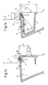
- FIGS. 1a, 1b an attachment according to the invention of a side rail panel 1 is shown on a side member 2 of a motor vehicle in two sections.
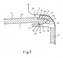
- FIG. 2 shows the area of the catch in an enlarged section FIG. 1 b.
- the longitudinal member 2 has in the region of the attachment to a depression in which a holding element 3 is fixed.
- a breakthrough is introduced in the side member, in which a retaining pin 18 is inserted on the holding element 3.
- the holding element 3 has a U-shaped latching slot 9 consisting of a holding leg 10 and a Verrastungsschenkel 11 on.
- Verrastungsschenkel 11 a recess 12 for receiving the latching hook 8 on the locking element 4 of the side rail panel 1 is arranged.
- the side rail panel 1 has at its edge a locking element 4 for latching with the latching hook 8.
- Induction 5 is understood as meaning a step with which the surface 6 merges into a surface 6a drawn in at the level of the step.
- the surfaces 6, 6a are arranged substantially parallel to one another, and the thickness of the side rail panel 1 outside of the latching element 4 is thereby smaller than the thickness on the latching element 4.
- a latching hook 8 is arranged at the indentation 5 opposite in the installed state of the side rail panel 1 invisible surface 7 of the side rail panel 1.
- This latching hook 8 is triangular in cross-section, starting from the arranged at the top of the locking element 4 nose 13 of the locking hooks 8 has an insertion bevel 14, which merges at its nose 13 remote from the end into a retaining bevel 15.
- the insertion bevel 14, or their angle ⁇ the force is set with the side rail panel 1 must be pressed until it locks.
- the support bevel 15, and their angle ⁇ the holding force of the latch is set.
- the mentioned angles are in the FIG. 1b located.
- FIG. 1b also shows that the insertion bevel 14 on the nose 13 at an angle ⁇ merges into a bump 16. This area with the angle ⁇ serves as a centering aid when pressed in.
- the retaining slope 15 facing wall 17 of the recess 12 is adapted in the Verrastungsschenkel 11 to the contour of the retaining bevel 15, resulting in the VerrastungsSullivan the latching hook 8 in the recess 12, a flat support or investment.
- the attachment of the side rail panel 1 to the side rail by means of a holding element 3 has thermal expansion compensating integrated elements without the use of additional fasteners.
- the arrangement of the latching hooks 8, which serve for the fastening, are integrated in the molded part or the side rail panel 1 in such a way that they can be produced without marking, ie. are on the invisible surface. This represents an essential quality feature.
- the arrangement of the components 1, 2, 3 is a so-called shadow gap 19, the separation edges, latching hooks, connections of sprues appear invisible.
- the attachment of the side rail panel 1 in the support member 3 is designed so that a thermal expansion in the longitudinal direction without deformation of the side rail panel 1 is possible.
- the longitudinal member 2 is designed with simple, preferably round recesses in recording quality. Then the holding elements 3 are attached with retaining pins 18 with integrated heat balance system. A simple assembly and disassembly is also feasible here.
- the recording quality of the recesses in the side member 2 ensure accurate positioning of the trim components or the side rail panel 1. Thereafter, the side rail panel 1 is simply brought by means of abutment 16 and insertion bevel 14 in the mounting position and locked.
- the latching forces are designed so that the latching forces ⁇ 50 N and the pull-off forces> 150 N reach.
- the integrated heat elements ensure a temperature compensation between the usual test temperatures of -30 ° / + 90 ° Celsius, without visible deformation on the side rail panel 1 occur.
- F 15 mm
Landscapes
- Engineering & Computer Science (AREA)
- Mechanical Engineering (AREA)
- Connection Of Plates (AREA)
- Vehicle Interior And Exterior Ornaments, Soundproofing, And Insulation (AREA)
- Slide Fasteners, Snap Fasteners, And Hook Fasteners (AREA)
- Insertion Pins And Rivets (AREA)
- Road Paving Structures (AREA)
- Clamps And Clips (AREA)
Description
- Die Erfindung betrifft eine Befestigung einer Längsträgerverkleidung an einem Längsträger eines Kraftfahrzeugs mit einem Halteelement, welches am Längsträger befestigt ist und die Längsträgerverkleidung an ihrem zum Halteelement gewandten Endbereich ein Rastelement aufweist, mit dem die Längsträgerverkleidung am Halteelement verrastet ist.
- Längsträgerverkleidungen (auch als Schweller bezeichnet) werden gewöhnlich mit unterschiedlichsten Befestigungsmaterialien am Längsträger bzw. der Karosserie befestigt. Bevorzugt werden die Längsträgerverkleidungen mit einer Verrastung befestigt, wobei die Verrastungseinheiten an der Längsträgerverkleidung angeformt sind, um zusätzliches Befestigungsmaterial zu sparen.
- In den meisten Fällen werden die angeformten Verrastungen an der Längsträgerverkleidung so ausgebildet, dass sichtbare Einfallstellen entstehen und die Längsträgerverkleidung oft in unterschiedlichen Richtungen montiert werden muss. Die montierende Person kann in den meisten Fällen auch nicht genau feststellen, ob die Verrastung in Ordnung ist oder die Rastelemente verformt und somit wirkungslos sind. Eine Befestigung einer Längsträgerverkleidung an einem Längsträger eines Kraftfahrzeug nach dem Oberbegriff des Anspruchs 1 ist aus dem Dokument
DE 102006001028 A bekannt. - Der Erfindung liegt die Aufgabe zugrunde, eine Befestigung einer Längsträger-verkleidung an einem Längsträger eines Kraftfahrzeugs nach dem Oberbegriff des Anspruchs 1 so zu verbessern, dass das Bauvolumen der Befestigung im Vergleich zum Stand der Technik verringert ist. Außerdem soll eine einfache Montage und Demontage in einer Montagerichtung erreicht werden und eine sichere abzeichnungsfreie Optik ohne zusätzliches Befestigungsmaterial erreicht werden.
- Erfindungsgemäß wird diese Aufgabe durch den Anspruch 1 gelöst. Hierdurch ist das Bauvolumen der Befestigung im Vergleich zum Stand der Technik verringert. Die Verringerung beträgt mindestens die Höhe des Einzuges.
- In bevorzugter Ausführungsform weist das Halteelement einen U-förmigen Verrastungsschlitz bestehend aus einem Halteschenkel und einem Verrastungsschenkel auf und ist im Verrastungsschenkel eine Ausnehmung zur Aufnahme des Rasthakens am Rastelement der Längsträgerverkleidung angeordnet. Diese Art Verrastungsschlitz benötigt eine extrem geringe Bauhöhe bei gleichzeitiger guter Verrastung. Außerdem ist die Verrastung im Falle einer Reparatur wieder lösbar.
- In bevorzugter Ausführungsform weist der Rasthaken einen dreieckigen Querschnitt auf, wobei ausgehend von der an der Spitze des Rastelements angeordneten Nase der Rasthaken eine Einführschräge aufweist, die an ihrem der Nase abgewandten Ende in eine Halteschräge übergeht. Die Einführschräge bzw. deren Schräge bestimmt die Eindrückkraft, d.h. die Kraft die aufgewendet werden muss, damit die Verrastung ermöglicht wird. Die Halteschräge bzw. deren Schräge bestimmt die Haltekraft, d.h. die Kraft mit der der Rasthaken in der Ausnehmung verrastet ist.
- Es hat sich als vorteilhaft herausgestellt, wenn ausgehend von der Nase die Einführschräge in einem Winkel 20° < α < 55°, bevorzugt 30° < α < 45°, besonders bevorzugt 35° < α < 40° zur im Einbauzustand der Längsträgerverkleidung unsichtbaren Oberfläche der Längsträgerverkleidung verläuft.
- Es hat sich weiterhin als vorteilhaft herausgestellt, wenn ausgehend von dem der Nase abgewandten Ende die Halteschräge des Rasthakens in einem Winkel 40° < β < 80°, bevorzugt 50° < β < 70°, besonders bevorzugt 55° < β < 65° zur im Einbauzustand der Längsträgerverkleidung unsichtbaren Oberfläche der Längsträgerverkleidung verläuft.
- Bevorzugt geht die Einführschräge an der Nase in eine Stoßschräge über, die in einem Winkel 60° < γ < 120°, bevorzugt 80° < γ < 100° zur Einführschräge angeordnet ist. Diese Stoßschräge ist ein Zentrierelement beim Einrastvorgang.
- In bevorzugter Weiterbildung ist die der Halteschräge zugewandte Wand der Ausnehmung im Verrastungsschenkel an die Kontur der Halteschräge angepasst, wodurch sich im Verrastungszustand des Rasthakens in der Ausnehmung eine flächige Auflage ergibt. Flächige Auflagen verteilen die auftretenden Kräfte.
- Bevorzugt sind die Rasthaken so angebracht, dass sie sich bei der Montage nicht verformen können und keine Oberflächenabzeichnungen auf der im Einbauzustand der Längsträgerverkleidung unsichtbaren Oberfläche der Längsträgerverkleidung ergeben.
- Zur dauerhaften Befestigung und unter Einhaltung von Spaltvorgaben wird somit vorgeschlagen, dass die Längsträgerverkleidung angeformte Rasthaken aufweist, die in einer am Längsträger 2 befestigten Halteleiste einfährt und verrastet.
- Nachfolgend wird die Erfindung anhand von Figuren weiter erläutert.
- In den
Figuren 1a, 1b ist eine erfindungsgemäße Befestigung einer Längsträgerverkleidung 1 an einem Längsträger 2 eines Kraftfahrzeugs in zwei Schnitten gezeigt.Figur 2 zeigt den Bereich der Verrastung in einem vergrößerten Ausschnitt ausFigur 1 b. - Der Längsträger 2 weist im Bereich der Befestigung eine Senke auf, in der ein Halteelement 3 befestigt ist. Hierzu ist im Längsträger ein Durchbruch eingebracht, in den ein Haltestift 18 am Halteelement 3 eingesteckt ist. Zur Befestigung der Längsträgerverkleidung 1 weist das Halteelement 3 einen U-förmigen Verrastungsschlitz 9 bestehend aus einem Halteschenkel 10 und einem Verrastungsschenkel 11 auf. Im Verrastungsschenkel 11 ist eine Ausnehmung 12 zur Aufnahme des Rasthakens 8 am Rastelement 4 der Längsträgerverkleidung 1 angeordnet.
- Die Längsträgerverkleidung 1 weist an ihrem Rand ein Rastelement 4 zur Verrastung mit dem Rasthaken 8 auf. Erfindungsgemäß geht die im Einbauzustand der Längsträgerverkleidung 1 sichtbare Oberfläche 6 der Längsträgerverkleidung 1 am Rastelement 4 in einen Einzug 5 über. Unter Einzug 5 wird eine Stufe verstanden, mit der die Oberfläche 6 in eine in Höhe der Stufe eingezogene Oberfläche 6a übergeht. Die Oberflächen 6, 6a sind im Wesentlichen parallel zueinander angeordnet und die Dicke der Längsträgerverkleidung 1 außerhalb des Rastelements 4 ist dadurch geringer als die Dicke am Rastelement 4.
- An der dem Einzug 5 gegenüberliegenden im Einbauzustand der Längsträgerverkleidung 1 unsichtbaren Oberfläche 7 der Längsträgerverkleidung 1 ist ein Rasthaken 8 angeordnet. Dieser Rasthaken 8 ist im Querschnitt dreieckförmig ausgebildet, wobei ausgehend von der an der Spitze des Rastelements 4 angeordneten Nase 13 der Rasthaken 8 eine Einführschräge 14 aufweist, die an ihrem der Nase 13 abgewandten Ende in eine Halteschräge 15 übergeht. Mit der Einführschräge 14, bzw. deren Winkel α wird die Kraft eingestellt, mit der die Längsträgerverkleidung 1 bis zur Verrastung eingedrückt werden muss. Mit der Halteschräge 15, bzw. deren Winkel β wird die Haltekraft der Verrastung eingestellt. Die genannten Winkel sind in die
Figur 1b eingezeichnet.Figur 1b zeigt auch, dass die Einführschräge 14 an der Nase 13 in einem Winkel γ in eine Stoßschräge 16 übergeht. Dieser Bereich mit dem Winkel γ dient beim Eindrücken als Zentrierhilfe. - In der hier gezeigten Ausführungsform ist die der Halteschräge 15 zugewandte Wand 17 der Ausnehmung 12 im Verrastungsschenkel 11 an die Kontur der Halteschräge 15 angepasst, wodurch sich im Verrastungszustand des Rasthakens 8 in der Ausnehmung 12 eine flächige Auflage oder Anlage ergibt.
- Die Befestigung der Längsträgerverkleidung 1 an dem Längsträger mittels eines Halteelementes 3 hat Wärmedehnung ausgleichende integrierte Elemente ohne Inanspruchnahme zusätzlicher Befestigungselemente. Die Anordnung der Rasthaken 8, die der Befestigung dienen, sind so im Formteil bzw. der Längsträgerverkleidung 1 integriert, dass diese abzeichnungsfrei herstellbar sind, d.h. befinden sich auf der nicht sichtbaren Oberfläche. Dies stellt ein wesentliches Qualitätsmerkmal dar. Zusätzlich stellt die Anordnung der Bauteile 1, 2, 3 eine so genannte Schattenfuge 19 dar, die Trennkanten, Rasthaken, Anbindungen von Angüssen nicht sichtbar erscheinen lässt.
- Die Befestigung der Längsträgerverkleidung 1 im Halteelement 3 ist so gestaltet, dass eine Wärmeausdehnung in Längsrichtung ohne Verformungen der Längsträgerverkleidung 1 möglich ist.
- Der Längsträger 2 wird mit einfachen bevorzugt runden Ausnehmungen in Aufnahmequalität ausgelegt. Darauf werden die Halteelemente 3 mit Haltestiften 18 mit integriertem Wärmeausgleichssystem aufgesteckt. Eine einfache Montage sowie Demontage ist hier ebenso durchführbar.
- Die Aufnahmequalität der Ausnehmungen im Längsträger 2 gewährleisten eine exakte Positionierung der Verkleidungsbauteile bzw. der Längsträgerverkleidung 1. Danach wird die Längsträgerverkleidung 1 einfach mittels Stoßschräge 16 und Einführschräge 14 in Montageposition gebracht und verrastet. Die Rastkräfte sind so ausgelegt, dass die Einrastkräfte < 50 N und die Abzugskräfte > 150 N erreichen.
- Da der Werker die Rastpositionen nicht einsehen kann, ist die Einführung der Längsträgerverkleidung 1 in das Halteelement 3 auch als "Blind Operation" durchführbar. Dies geschieht mittels des Zentrierelementes, d.h. der Nase 13 und der Stoßschräge 16, die in die Längsträgerverkleidung 1 integriert sind und stellen zusätzlich eine sichtbare Markierung zur Sichtprüfung des Werkers dar.
- Außerdem ist eine einfache Demontage und Montage ermöglicht. Die integrierten Wärmeelemente gewährleisten einen Temperaturausgleich zwischen den üblichen Prüftemperaturen von -30° / +90° Celsius, ohne dass sichtbare Verformungen an der Längsträgerverkleidung 1 auftreten.
- Nachfolgend einige bevorzugte Größenangaben, wie sie in den Figuren gezeigt sind.
A = 1 mm G = 6 mm B = 2 mm H = 37 mm C = 19 mm α = 37° D = 3 mm β = 63° E = 2,5 mm γ = 80° F = 15 mm
Claims (6)
- Befestigung einer Verkleidung (1) an einem Träger (2) eines Kraftfahrzeugs mit einem Halteelement (3), welches am Träger (2) befestigt ist, wobei die Verkleidung (1) an ihrem zum Halteelement (3) gewandten Endbereich ein Rastelement (4) aufweist, mit dem die Verkleidung (1) am Halteelement (3) verrastet ist, wobei das Rastelement (4) einen die Dicke reduzierenden Einzug (5) zur angrenzenden im Einbauzustand der Verkleidung (1) sichtbaren Oberfläche (6) der Verkleidung (1) aufweist und an der dem Einzug (5) gegenüberliegenden im Einbauzustand der Verkleidung (1) unsichtbaren Oberfläche (7) der Verkleidung (1) das Rastelement (4) einen Rasthaken (8) aufweist, dadurch gekennzeichnet, dass die Verkleidung eine Längsträgerverkleidung ist und der Träger ein Längsträger ist, und dass das Halteelement (3) einen U-förmigen Verrastungsschlitz (9) bestehend aus einem Halteschenkel (10) und einem Verrastungsschenkel (11) aufweist und im Verrastungsschenkel (11) eine Ausnehmung (12) zur Aufnahme des Rasthakens (8) am Rastelement (4) der Längsträgerverkleidung (1) angeordnet ist.
- Befestigung nach Anspruch 1, dadurch gekennzeichnet, dass der Rasthaken (8) einen dreieckigen Querschnitt aufweist, wobei ausgehend von der an der Spitze des Rastelements (4) angeordneten Nase (13) der Rasthaken (8) eine Einführschräge (14) aufweist, die an ihrem der Nase (13) abgewandten Ende in eine Halteschräge (15) übergeht.
- Befestigung nach Anspruch 2, dadurch gekennzeichnet, dass ausgehend von der Nase (13) die Einführschräge (14) in einem Winkel 20° < α < 55°, bevorzugt 30° < α < 45°, besonders bevorzugt 35° < α < 40° zur im Einbauzustand der Längsträgerverkleidung (1) unsichtbaren Oberfläche (7) der Längsträgerverkleidung (1) verläuft.
- Befestigung nach Anspruch 2 oder 3, dadurch gekennzeichnet, dass ausgehend von dem der Nase (13) abgewandten Ende die Halteschräge (15) des Rasthakens (8) in einem Winkel 40° < β < 80°, bevorzugt 50° < β < 70°, besonders bevorzugt 55° < β < 65° zur im Einbauzustand der Längsträgerverkleidung (1) unsichtbaren Oberfläche (7) der Längsträgerverkleidung (1) verläuft.
- Befestigung nach einem der Ansprüche 2 bis 4, dadurch gekennzeichnet, dass die Einführschräge (14) an der Nase (13) in eine Stoßschräge (16) übergeht, die in einem Winkel 60° < γ < 120°, bevorzugt 80° < γ < 100° zur Einführschräge (14) angeordnet ist.
- Befestigung nach einem der Ansprüche 1 bis 5, dadurch gekennzeichnet, dass die der Halteschräge (15) zugewandte Wand (17) der Ausnehmung (12) im Verrastungsschenkel (11) an die Kontur der Halteschräge (15) angepasst ist, wodurch sich im Verrastungszustand des Rasthakens (8) in der Ausnehmung (12) eine flächige Auflage ergibt.
Applications Claiming Priority (2)
| Application Number | Priority Date | Filing Date | Title |
|---|---|---|---|
| DE201010004978 DE102010004978A1 (de) | 2010-01-18 | 2010-01-18 | Befestigung einer Längsträgerverkleidung an einem Längsträger eines Kraftfahrzeugs |
| PCT/EP2011/050290 WO2011086072A1 (de) | 2010-01-18 | 2011-01-12 | Befestigung einer längsträgerverkleidung an einem längsträger eines kraftfahrzeugs |
Publications (3)
| Publication Number | Publication Date |
|---|---|
| EP2525999A1 EP2525999A1 (de) | 2012-11-28 |
| EP2525999B1 EP2525999B1 (de) | 2013-12-04 |
| EP2525999B2 true EP2525999B2 (de) | 2018-12-05 |
Family
ID=43806901
Family Applications (1)
| Application Number | Title | Priority Date | Filing Date |
|---|---|---|---|
| EP11700830.0A Active EP2525999B2 (de) | 2010-01-18 | 2011-01-12 | Befestigung einer längsträgerverkleidung an einem längsträger eines kraftfahrzeugs |
Country Status (6)
| Country | Link |
|---|---|
| US (1) | US8857879B2 (de) |
| EP (1) | EP2525999B2 (de) |
| CN (1) | CN102939220B (de) |
| DE (1) | DE102010004978A1 (de) |
| ES (1) | ES2440969T5 (de) |
| WO (1) | WO2011086072A1 (de) |
Families Citing this family (9)
| Publication number | Priority date | Publication date | Assignee | Title |
|---|---|---|---|---|
| DE102009038134A1 (de) * | 2009-08-13 | 2011-02-17 | Decoma (Germany) Gmbh | Verbindungsmodul |
| EP3082428A4 (de) | 2013-12-09 | 2017-08-02 | Respira Therapeutics, Inc. | Pde5-inhibitorpulverformulierungen und zugehörige verfahren |
| DE202014006302U1 (de) | 2014-09-05 | 2014-09-16 | Magna Exteriors Gmbh | Befestigung einer Kunststoffverkleidung an einer Tragstruktur eines Kraftfahrzeuges |
| US9827919B2 (en) * | 2015-10-08 | 2017-11-28 | GM Global Technology Operations LLC | Vehicle floor bracket |
| DE202015107057U1 (de) * | 2015-12-23 | 2017-03-27 | Rehau Ag + Co | Schwellerverkleidung |
| DE102016204483B4 (de) * | 2016-03-17 | 2021-06-17 | Volkswagen Aktiengesellschaft | Befestigungselement mit mindestens einem Clip zur Herstellung einer Verbindung mit einem korrespondierenden Ansteckelement und Anordnung eines Befestigungselements an einem Ansteckelement |
| DE102018009156A1 (de) | 2018-11-21 | 2019-04-25 | Daimler Ag | Befestigungsvorrichtung, Befestigungsanordnung, Montageverfahren sowie Demontageverfahren |
| JP2023003018A (ja) * | 2021-06-23 | 2023-01-11 | トヨタ自動車株式会社 | ロッカモール |
| JP7792280B2 (ja) * | 2022-03-23 | 2025-12-25 | 本田技研工業株式会社 | ドアビームのキャッチャー構造 |
Citations (2)
| Publication number | Priority date | Publication date | Assignee | Title |
|---|---|---|---|---|
| DE9420291U1 (de) † | 1994-12-19 | 1995-10-19 | Siemens AG, 80333 München | Gehäuse aus zumindest zwei mittels einer Nut-Feder-Verbindung zusammensetzbaren Gehäuseteilen |
| DE19507986A1 (de) † | 1995-03-07 | 1996-09-12 | Audi Ag | Festlegung eines Kunststoff-Formteiles an einem Absatz einer Fahrzeugkarosserie |
Family Cites Families (23)
| Publication number | Priority date | Publication date | Assignee | Title |
|---|---|---|---|---|
| DE2628233A1 (de) * | 1976-06-23 | 1978-01-05 | Paul Winiger | Tuerkantenschutz an kraftfahrzeug |
| DE2848762A1 (de) * | 1978-11-10 | 1980-05-22 | Porsche Ag | Schutzleiste fuer einen ausschwenkbaren flansch einer tuer, haube o.dgl. eines kraftfahrzeuges |
| JPH0621830Y2 (ja) * | 1988-03-11 | 1994-06-08 | 本田技研工業株式会社 | 自動車のサイドシル構造 |
| DE19636505C1 (de) | 1996-09-09 | 1998-01-22 | Daimler Benz Ag | Türeinstiegbereich für ein Kraftfahrzeug |
| DE20009877U1 (de) | 2000-05-24 | 2000-08-10 | Petri Ag, 63743 Aschaffenburg | Lenkradverkleidung |
| JP3681117B2 (ja) * | 2001-11-16 | 2005-08-10 | 本田技研工業株式会社 | 車両における長尺状樹脂部材の分割構造 |
| DE10240390A1 (de) * | 2002-09-02 | 2004-03-11 | Arvinmeritor Gmbh | Schiebehimmel für ein Kfz-Schiebe- oder -Schiebehebedach |
| DE602004022833D1 (de) * | 2003-08-28 | 2009-10-08 | Decoma Int Inc | Fahrzeugaufbauplatte mit integraler klammer |
| JP4211713B2 (ja) * | 2003-09-05 | 2009-01-21 | トヨタ紡織株式会社 | 結合構造 |
| JP3920257B2 (ja) * | 2003-10-15 | 2007-05-30 | 本田技研工業株式会社 | サイドシルガーニッシュの取付構造 |
| KR100527972B1 (ko) * | 2003-10-17 | 2005-11-09 | 현대자동차주식회사 | 자동차 도어 스카프 트림 고정 구조 |
| DE102004005963B4 (de) * | 2004-02-06 | 2007-12-06 | Decoma (Germany) Gmbh | Befestigungselement |
| DE102004015348B4 (de) * | 2004-03-30 | 2007-11-29 | Dr.Ing.H.C. F. Porsche Ag | Betätigungseinrichtung zum Entriegeln eines bewegbaren Deckels eines Kraftfahrzeugs |
| DE102005036910B4 (de) * | 2005-08-05 | 2008-04-03 | Audi Ag | Anordnung mit einem Funktionsteil-Gehäuse und einer anfügbaren Blende an einem Kraftfahrzeug |
| US20070085361A1 (en) * | 2005-10-19 | 2007-04-19 | Christian Hauser | Injection molded parts for vehicles and other devices |
| DE102006001028A1 (de) * | 2006-01-02 | 2007-07-12 | Decoma (Germany) Gmbh | Verkleidungsteil |
| DE102006034977A1 (de) * | 2006-07-28 | 2008-01-31 | Bayerische Motoren Werke Ag | Seitenschweller einer Karosserie eines Kraftfahrzeugs |
| US7644975B2 (en) * | 2007-04-03 | 2010-01-12 | Honda Motor Co., Ltd. | Mounting arrangement for mounting cladding to vehicle body |
| DE102007062254A1 (de) * | 2007-12-21 | 2009-06-25 | GM Global Technology Operations, Inc., Detroit | Abstützung einer Einstiegsverkleidung an einem Trageelement eines Kraftfahrzeugs |
| JP4688915B2 (ja) * | 2008-09-29 | 2011-05-25 | 株式会社ホンダアクセス | サイドアンダースポイラー取付構造 |
| US8322110B2 (en) * | 2009-02-25 | 2012-12-04 | Ford Global Technologies, Llc | Trim flap-like closeout edge attachment |
| US8276961B2 (en) * | 2011-01-26 | 2012-10-02 | Nissan North America, Inc. | Vehicle trim assembly |
| US8534744B2 (en) * | 2011-09-01 | 2013-09-17 | Toyota Motor Engineering & Manufacturing North America, Inc. | Pillar garnishments, interior garnishment assemblies incorporating the same, and methods for controlling alignment of interior garnishment assemblies |
-
2010
- 2010-01-18 DE DE201010004978 patent/DE102010004978A1/de active Pending
-
2011
- 2011-01-12 ES ES11700830T patent/ES2440969T5/es active Active
- 2011-01-12 CN CN201180006361.1A patent/CN102939220B/zh not_active Expired - Fee Related
- 2011-01-12 EP EP11700830.0A patent/EP2525999B2/de active Active
- 2011-01-12 US US13/522,105 patent/US8857879B2/en active Active
- 2011-01-12 WO PCT/EP2011/050290 patent/WO2011086072A1/de not_active Ceased
Patent Citations (2)
| Publication number | Priority date | Publication date | Assignee | Title |
|---|---|---|---|---|
| DE9420291U1 (de) † | 1994-12-19 | 1995-10-19 | Siemens AG, 80333 München | Gehäuse aus zumindest zwei mittels einer Nut-Feder-Verbindung zusammensetzbaren Gehäuseteilen |
| DE19507986A1 (de) † | 1995-03-07 | 1996-09-12 | Audi Ag | Festlegung eines Kunststoff-Formteiles an einem Absatz einer Fahrzeugkarosserie |
Also Published As
| Publication number | Publication date |
|---|---|
| EP2525999A1 (de) | 2012-11-28 |
| EP2525999B1 (de) | 2013-12-04 |
| CN102939220B (zh) | 2015-04-08 |
| US8857879B2 (en) | 2014-10-14 |
| DE102010004978A1 (de) | 2011-07-21 |
| US20120292938A1 (en) | 2012-11-22 |
| ES2440969T3 (es) | 2014-01-31 |
| CN102939220A (zh) | 2013-02-20 |
| ES2440969T5 (es) | 2019-05-10 |
| WO2011086072A1 (de) | 2011-07-21 |
Similar Documents
| Publication | Publication Date | Title |
|---|---|---|
| EP2525999B1 (de) | Befestigung einer längsträgerverkleidung an einem längsträger eines kraftfahrzeugs | |
| DE102014118821B4 (de) | Elastisch verformbare Moduleinbauanordnung | |
| DE102014114086B4 (de) | System zur elastisch gemittelten Ausrichtung | |
| DE10357448B4 (de) | Rastverbindungsteil zur Befestigung eines Gassackmoduls | |
| DE202009006367U1 (de) | Vorrichtung zur Befestigung einer Tragschiene an einem Dachhaken | |
| EP3452732B1 (de) | Clip zum befestigen eines ersten elements an einem zweiten element und vorrichtung mit einem derartigen clip | |
| EP3526476A1 (de) | Clip mit schwimmender lagerung | |
| EP3238569B1 (de) | Vorrichtung zur anbringung einer rückwand an ein bewegbares möbelteil | |
| WO2020120067A1 (de) | Bürstenmodul und verfahren zur montage | |
| DE102024123899A1 (de) | Befestigungsklammer | |
| WO2008077858A1 (de) | Halterung | |
| EP3563649B1 (de) | Bauteilhaltevorrichtung | |
| EP3529868B1 (de) | Verbindungsanordnung für die verbindung von zwei schaltschrankrahmengestellen | |
| DE102016204483B4 (de) | Befestigungselement mit mindestens einem Clip zur Herstellung einer Verbindung mit einem korrespondierenden Ansteckelement und Anordnung eines Befestigungselements an einem Ansteckelement | |
| DE102011051613A1 (de) | Befestigungssystem für einen Kraftfahrzeugdachträger | |
| DE102015204729A1 (de) | Verbindungsanordnung zum Ausgleich fertigungs- und/oder montagebedingter Toleranzen zwischen Bauteilen | |
| EP2418451B1 (de) | Anordnung umfassend einen Wärmeübertrager, eine weitere Komponente und eine Modulhalterung | |
| DE102015217463A1 (de) | Halter zur Befestigung an einem Strukturteil eines Kraftfahrzeuges sowie Anordnung eines Halters an einem Strukturteil eines Kraftfahrzeuges | |
| EP2512866B1 (de) | Vorrichtung zum fixieren eines gegenstandes in einer vertiefung | |
| DE102010005309A1 (de) | Verkleidungsteil mit mindestens einem Befestigungsmittel zur Befestigung an einer Fahrzeugkarosserie | |
| DE202011050843U1 (de) | Steckverbinder | |
| DE202010008544U1 (de) | Structural-Glazing-Konstruktion | |
| EP2017104B1 (de) | Befestigungseinrichtung für eine bewegbare Scheibe eines Kraftfahrzeuges | |
| DE102021133257B4 (de) | Montageschutzvorrichtung für Türdichtungen | |
| DE202014101563U1 (de) | Verbinder zur Befestigung von Pfosten und Riegeln |
Legal Events
| Date | Code | Title | Description |
|---|---|---|---|
| PUAI | Public reference made under article 153(3) epc to a published international application that has entered the european phase |
Free format text: ORIGINAL CODE: 0009012 |
|
| 17P | Request for examination filed |
Effective date: 20120820 |
|
| AK | Designated contracting states |
Kind code of ref document: A1 Designated state(s): AL AT BE BG CH CY CZ DE DK EE ES FI FR GB GR HR HU IE IS IT LI LT LU LV MC MK MT NL NO PL PT RO RS SE SI SK SM TR |
|
| DAX | Request for extension of the european patent (deleted) | ||
| GRAP | Despatch of communication of intention to grant a patent |
Free format text: ORIGINAL CODE: EPIDOSNIGR1 |
|
| INTG | Intention to grant announced |
Effective date: 20130701 |
|
| GRAS | Grant fee paid |
Free format text: ORIGINAL CODE: EPIDOSNIGR3 |
|
| GRAA | (expected) grant |
Free format text: ORIGINAL CODE: 0009210 |
|
| AK | Designated contracting states |
Kind code of ref document: B1 Designated state(s): AL AT BE BG CH CY CZ DE DK EE ES FI FR GB GR HR HU IE IS IT LI LT LU LV MC MK MT NL NO PL PT RO RS SE SI SK SM TR |
|
| REG | Reference to a national code |
Ref country code: GB Ref legal event code: FG4D Free format text: NOT ENGLISH |
|
| REG | Reference to a national code |
Ref country code: CH Ref legal event code: EP |
|
| REG | Reference to a national code |
Ref country code: IE Ref legal event code: FG4D Free format text: LANGUAGE OF EP DOCUMENT: GERMAN Ref country code: AT Ref legal event code: REF Ref document number: 643406 Country of ref document: AT Kind code of ref document: T Effective date: 20140115 |
|
| REG | Reference to a national code |
Ref country code: DE Ref legal event code: R096 Ref document number: 502011001750 Country of ref document: DE Effective date: 20140130 |
|
| REG | Reference to a national code |
Ref country code: ES Ref legal event code: FG2A Ref document number: 2440969 Country of ref document: ES Kind code of ref document: T3 Effective date: 20140131 |
|
| REG | Reference to a national code |
Ref country code: NL Ref legal event code: VDEP Effective date: 20131204 |
|
| PG25 | Lapsed in a contracting state [announced via postgrant information from national office to epo] |
Ref country code: LT Free format text: LAPSE BECAUSE OF FAILURE TO SUBMIT A TRANSLATION OF THE DESCRIPTION OR TO PAY THE FEE WITHIN THE PRESCRIBED TIME-LIMIT Effective date: 20131204 Ref country code: FI Free format text: LAPSE BECAUSE OF FAILURE TO SUBMIT A TRANSLATION OF THE DESCRIPTION OR TO PAY THE FEE WITHIN THE PRESCRIBED TIME-LIMIT Effective date: 20131204 Ref country code: NO Free format text: LAPSE BECAUSE OF FAILURE TO SUBMIT A TRANSLATION OF THE DESCRIPTION OR TO PAY THE FEE WITHIN THE PRESCRIBED TIME-LIMIT Effective date: 20140304 Ref country code: SE Free format text: LAPSE BECAUSE OF FAILURE TO SUBMIT A TRANSLATION OF THE DESCRIPTION OR TO PAY THE FEE WITHIN THE PRESCRIBED TIME-LIMIT Effective date: 20131204 Ref country code: NL Free format text: LAPSE BECAUSE OF FAILURE TO SUBMIT A TRANSLATION OF THE DESCRIPTION OR TO PAY THE FEE WITHIN THE PRESCRIBED TIME-LIMIT Effective date: 20131204 Ref country code: HR Free format text: LAPSE BECAUSE OF FAILURE TO SUBMIT A TRANSLATION OF THE DESCRIPTION OR TO PAY THE FEE WITHIN THE PRESCRIBED TIME-LIMIT Effective date: 20131204 |
|
| REG | Reference to a national code |
Ref country code: LT Ref legal event code: MG4D |
|
| PG25 | Lapsed in a contracting state [announced via postgrant information from national office to epo] |
Ref country code: CY Free format text: LAPSE BECAUSE OF FAILURE TO SUBMIT A TRANSLATION OF THE DESCRIPTION OR TO PAY THE FEE WITHIN THE PRESCRIBED TIME-LIMIT Effective date: 20131204 Ref country code: RS Free format text: LAPSE BECAUSE OF FAILURE TO SUBMIT A TRANSLATION OF THE DESCRIPTION OR TO PAY THE FEE WITHIN THE PRESCRIBED TIME-LIMIT Effective date: 20131204 Ref country code: LV Free format text: LAPSE BECAUSE OF FAILURE TO SUBMIT A TRANSLATION OF THE DESCRIPTION OR TO PAY THE FEE WITHIN THE PRESCRIBED TIME-LIMIT Effective date: 20131204 |
|
| BERE | Be: lapsed |
Owner name: FAURECIA EXTERIORS G.M.B.H. Effective date: 20140131 |
|
| PG25 | Lapsed in a contracting state [announced via postgrant information from national office to epo] |
Ref country code: EE Free format text: LAPSE BECAUSE OF FAILURE TO SUBMIT A TRANSLATION OF THE DESCRIPTION OR TO PAY THE FEE WITHIN THE PRESCRIBED TIME-LIMIT Effective date: 20131204 Ref country code: IS Free format text: LAPSE BECAUSE OF FAILURE TO SUBMIT A TRANSLATION OF THE DESCRIPTION OR TO PAY THE FEE WITHIN THE PRESCRIBED TIME-LIMIT Effective date: 20140404 |
|
| REG | Reference to a national code |
Ref country code: DE Ref legal event code: R026 Ref document number: 502011001750 Country of ref document: DE |
|
| PG25 | Lapsed in a contracting state [announced via postgrant information from national office to epo] |
Ref country code: SK Free format text: LAPSE BECAUSE OF FAILURE TO SUBMIT A TRANSLATION OF THE DESCRIPTION OR TO PAY THE FEE WITHIN THE PRESCRIBED TIME-LIMIT Effective date: 20131204 Ref country code: CZ Free format text: LAPSE BECAUSE OF FAILURE TO SUBMIT A TRANSLATION OF THE DESCRIPTION OR TO PAY THE FEE WITHIN THE PRESCRIBED TIME-LIMIT Effective date: 20131204 Ref country code: LU Free format text: LAPSE BECAUSE OF FAILURE TO SUBMIT A TRANSLATION OF THE DESCRIPTION OR TO PAY THE FEE WITHIN THE PRESCRIBED TIME-LIMIT Effective date: 20140112 Ref country code: PL Free format text: LAPSE BECAUSE OF FAILURE TO SUBMIT A TRANSLATION OF THE DESCRIPTION OR TO PAY THE FEE WITHIN THE PRESCRIBED TIME-LIMIT Effective date: 20131204 Ref country code: PT Free format text: LAPSE BECAUSE OF FAILURE TO SUBMIT A TRANSLATION OF THE DESCRIPTION OR TO PAY THE FEE WITHIN THE PRESCRIBED TIME-LIMIT Effective date: 20140404 Ref country code: RO Free format text: LAPSE BECAUSE OF FAILURE TO SUBMIT A TRANSLATION OF THE DESCRIPTION OR TO PAY THE FEE WITHIN THE PRESCRIBED TIME-LIMIT Effective date: 20131204 |
|
| PLBI | Opposition filed |
Free format text: ORIGINAL CODE: 0009260 |
|
| REG | Reference to a national code |
Ref country code: CH Ref legal event code: PL |
|
| PG25 | Lapsed in a contracting state [announced via postgrant information from national office to epo] |
Ref country code: MC Free format text: LAPSE BECAUSE OF FAILURE TO SUBMIT A TRANSLATION OF THE DESCRIPTION OR TO PAY THE FEE WITHIN THE PRESCRIBED TIME-LIMIT Effective date: 20131204 |
|
| 26 | Opposition filed |
Opponent name: MAGNA EXTERIORS & INTERIORS (GERMANY) GMBH Effective date: 20140821 |
|
| PLAX | Notice of opposition and request to file observation + time limit sent |
Free format text: ORIGINAL CODE: EPIDOSNOBS2 |
|
| PG25 | Lapsed in a contracting state [announced via postgrant information from national office to epo] |
Ref country code: DK Free format text: LAPSE BECAUSE OF FAILURE TO SUBMIT A TRANSLATION OF THE DESCRIPTION OR TO PAY THE FEE WITHIN THE PRESCRIBED TIME-LIMIT Effective date: 20131204 Ref country code: CH Free format text: LAPSE BECAUSE OF NON-PAYMENT OF DUE FEES Effective date: 20140131 Ref country code: LI Free format text: LAPSE BECAUSE OF NON-PAYMENT OF DUE FEES Effective date: 20140131 |
|
| REG | Reference to a national code |
Ref country code: IE Ref legal event code: MM4A |
|
| REG | Reference to a national code |
Ref country code: DE Ref legal event code: R026 Ref document number: 502011001750 Country of ref document: DE Effective date: 20140821 |
|
| PLBB | Reply of patent proprietor to notice(s) of opposition received |
Free format text: ORIGINAL CODE: EPIDOSNOBS3 |
|
| PG25 | Lapsed in a contracting state [announced via postgrant information from national office to epo] |
Ref country code: BE Free format text: LAPSE BECAUSE OF NON-PAYMENT OF DUE FEES Effective date: 20140131 Ref country code: IE Free format text: LAPSE BECAUSE OF NON-PAYMENT OF DUE FEES Effective date: 20140112 |
|
| PG25 | Lapsed in a contracting state [announced via postgrant information from national office to epo] |
Ref country code: SI Free format text: LAPSE BECAUSE OF FAILURE TO SUBMIT A TRANSLATION OF THE DESCRIPTION OR TO PAY THE FEE WITHIN THE PRESCRIBED TIME-LIMIT Effective date: 20131204 |
|
| REG | Reference to a national code |
Ref country code: FR Ref legal event code: PLFP Year of fee payment: 6 |
|
| PG25 | Lapsed in a contracting state [announced via postgrant information from national office to epo] |
Ref country code: MT Free format text: LAPSE BECAUSE OF FAILURE TO SUBMIT A TRANSLATION OF THE DESCRIPTION OR TO PAY THE FEE WITHIN THE PRESCRIBED TIME-LIMIT Effective date: 20131204 |
|
| PG25 | Lapsed in a contracting state [announced via postgrant information from national office to epo] |
Ref country code: SM Free format text: LAPSE BECAUSE OF FAILURE TO SUBMIT A TRANSLATION OF THE DESCRIPTION OR TO PAY THE FEE WITHIN THE PRESCRIBED TIME-LIMIT Effective date: 20131204 |
|
| PG25 | Lapsed in a contracting state [announced via postgrant information from national office to epo] |
Ref country code: BG Free format text: LAPSE BECAUSE OF FAILURE TO SUBMIT A TRANSLATION OF THE DESCRIPTION OR TO PAY THE FEE WITHIN THE PRESCRIBED TIME-LIMIT Effective date: 20131204 Ref country code: GR Free format text: LAPSE BECAUSE OF FAILURE TO SUBMIT A TRANSLATION OF THE DESCRIPTION OR TO PAY THE FEE WITHIN THE PRESCRIBED TIME-LIMIT Effective date: 20140305 |
|
| PG25 | Lapsed in a contracting state [announced via postgrant information from national office to epo] |
Ref country code: HU Free format text: LAPSE BECAUSE OF FAILURE TO SUBMIT A TRANSLATION OF THE DESCRIPTION OR TO PAY THE FEE WITHIN THE PRESCRIBED TIME-LIMIT; INVALID AB INITIO Effective date: 20110112 Ref country code: TR Free format text: LAPSE BECAUSE OF FAILURE TO SUBMIT A TRANSLATION OF THE DESCRIPTION OR TO PAY THE FEE WITHIN THE PRESCRIBED TIME-LIMIT Effective date: 20131204 |
|
| APAH | Appeal reference modified |
Free format text: ORIGINAL CODE: EPIDOSCREFNO |
|
| APBM | Appeal reference recorded |
Free format text: ORIGINAL CODE: EPIDOSNREFNO |
|
| APBP | Date of receipt of notice of appeal recorded |
Free format text: ORIGINAL CODE: EPIDOSNNOA2O |
|
| APBQ | Date of receipt of statement of grounds of appeal recorded |
Free format text: ORIGINAL CODE: EPIDOSNNOA3O |
|
| REG | Reference to a national code |
Ref country code: FR Ref legal event code: PLFP Year of fee payment: 7 |
|
| REG | Reference to a national code |
Ref country code: AT Ref legal event code: MM01 Ref document number: 643406 Country of ref document: AT Kind code of ref document: T Effective date: 20160112 |
|
| PG25 | Lapsed in a contracting state [announced via postgrant information from national office to epo] |
Ref country code: AT Free format text: LAPSE BECAUSE OF NON-PAYMENT OF DUE FEES Effective date: 20160112 |
|
| REG | Reference to a national code |
Ref country code: FR Ref legal event code: PLFP Year of fee payment: 8 |
|
| APBU | Appeal procedure closed |
Free format text: ORIGINAL CODE: EPIDOSNNOA9O |
|
| REG | Reference to a national code |
Ref country code: DE Ref legal event code: R081 Ref document number: 502011001750 Country of ref document: DE Owner name: PLASTIC OMNIUM AUTOMOTIVE EXTERIORS GMBH, DE Free format text: FORMER OWNER: FAURECIA EXTERIORS GMBH, 91781 WEISSENBURG, DE |
|
| PG25 | Lapsed in a contracting state [announced via postgrant information from national office to epo] |
Ref country code: MK Free format text: LAPSE BECAUSE OF FAILURE TO SUBMIT A TRANSLATION OF THE DESCRIPTION OR TO PAY THE FEE WITHIN THE PRESCRIBED TIME-LIMIT Effective date: 20131204 |
|
| RAP2 | Party data changed (patent owner data changed or rights of a patent transferred) |
Owner name: PLASTIC OMNIUM AUTOMOTIVE EXTERIORS GMBH |
|
| PG25 | Lapsed in a contracting state [announced via postgrant information from national office to epo] |
Ref country code: AL Free format text: LAPSE BECAUSE OF FAILURE TO SUBMIT A TRANSLATION OF THE DESCRIPTION OR TO PAY THE FEE WITHIN THE PRESCRIBED TIME-LIMIT Effective date: 20131204 |
|
| PUAH | Patent maintained in amended form |
Free format text: ORIGINAL CODE: 0009272 |
|
| STAA | Information on the status of an ep patent application or granted ep patent |
Free format text: STATUS: PATENT MAINTAINED AS AMENDED |
|
| 27A | Patent maintained in amended form |
Effective date: 20181205 |
|
| AK | Designated contracting states |
Kind code of ref document: B2 Designated state(s): AL AT BE BG CH CY CZ DE DK EE ES FI FR GB GR HR HU IE IS IT LI LT LU LV MC MK MT NL NO PL PT RO RS SE SI SK SM TR |
|
| REG | Reference to a national code |
Ref country code: DE Ref legal event code: R102 Ref document number: 502011001750 Country of ref document: DE |
|
| PGFP | Annual fee paid to national office [announced via postgrant information from national office to epo] |
Ref country code: DE Payment date: 20190227 Year of fee payment: 15 |
|
| REG | Reference to a national code |
Ref country code: ES Ref legal event code: DC2A Ref document number: 2440969 Country of ref document: ES Kind code of ref document: T5 Effective date: 20190510 |
|
| REG | Reference to a national code |
Ref country code: DE Ref legal event code: R082 Ref document number: 502011001750 Country of ref document: DE Representative=s name: STUMPF PATENTANWAELTE PARTGMBB, DE |
|
| PG25 | Lapsed in a contracting state [announced via postgrant information from national office to epo] |
Ref country code: IT Free format text: LAPSE BECAUSE OF NON-PAYMENT OF DUE FEES Effective date: 20200112 |
|
| PGFP | Annual fee paid to national office [announced via postgrant information from national office to epo] |
Ref country code: ES Payment date: 20210326 Year of fee payment: 11 |
|
| PGFP | Annual fee paid to national office [announced via postgrant information from national office to epo] |
Ref country code: GB Payment date: 20220119 Year of fee payment: 12 |
|
| REG | Reference to a national code |
Ref country code: ES Ref legal event code: FD2A Effective date: 20230303 |
|
| PG25 | Lapsed in a contracting state [announced via postgrant information from national office to epo] |
Ref country code: ES Free format text: LAPSE BECAUSE OF NON-PAYMENT OF DUE FEES Effective date: 20220113 |
|
| P01 | Opt-out of the competence of the unified patent court (upc) registered |
Effective date: 20230517 |
|
| REG | Reference to a national code |
Ref country code: DE Ref legal event code: R119 Ref document number: 502011001750 Country of ref document: DE |
|
| GBPC | Gb: european patent ceased through non-payment of renewal fee |
Effective date: 20230112 |
|
| PG25 | Lapsed in a contracting state [announced via postgrant information from national office to epo] |
Ref country code: GB Free format text: LAPSE BECAUSE OF NON-PAYMENT OF DUE FEES Effective date: 20230112 Ref country code: DE Free format text: LAPSE BECAUSE OF NON-PAYMENT OF DUE FEES Effective date: 20230801 |
|
| PGFP | Annual fee paid to national office [announced via postgrant information from national office to epo] |
Ref country code: FR Payment date: 20250130 Year of fee payment: 15 |