EP2520500A1 - Schneidstation mit Komplettschnittwerkzeug - Google Patents
Schneidstation mit Komplettschnittwerkzeug Download PDFInfo
- Publication number
- EP2520500A1 EP2520500A1 EP12003140A EP12003140A EP2520500A1 EP 2520500 A1 EP2520500 A1 EP 2520500A1 EP 12003140 A EP12003140 A EP 12003140A EP 12003140 A EP12003140 A EP 12003140A EP 2520500 A1 EP2520500 A1 EP 2520500A1
- Authority
- EP
- European Patent Office
- Prior art keywords
- packaging machine
- thermoforming packaging
- cutting tool
- cutting
- tool
- Prior art date
- Legal status (The legal status is an assumption and is not a legal conclusion. Google has not performed a legal analysis and makes no representation as to the accuracy of the status listed.)
- Granted
Links
Images



Classifications
-
- B—PERFORMING OPERATIONS; TRANSPORTING
- B65—CONVEYING; PACKING; STORING; HANDLING THIN OR FILAMENTARY MATERIAL
- B65B—MACHINES, APPARATUS OR DEVICES FOR, OR METHODS OF, PACKAGING ARTICLES OR MATERIALS; UNPACKING
- B65B9/00—Enclosing successive articles, or quantities of material, e.g. liquids or semiliquids, in flat, folded, or tubular webs of flexible sheet material; Subdividing filled flexible tubes to form packages
- B65B9/02—Enclosing successive articles, or quantities of material between opposed webs
- B65B9/04—Enclosing successive articles, or quantities of material between opposed webs one or both webs being formed with pockets for the reception of the articles, or of the quantities of material
-
- B—PERFORMING OPERATIONS; TRANSPORTING
- B26—HAND CUTTING TOOLS; CUTTING; SEVERING
- B26F—PERFORATING; PUNCHING; CUTTING-OUT; STAMPING-OUT; SEVERING BY MEANS OTHER THAN CUTTING
- B26F1/00—Perforating; Punching; Cutting-out; Stamping-out; Apparatus therefor
- B26F1/38—Cutting-out; Stamping-out
- B26F1/40—Cutting-out; Stamping-out using a press, e.g. of the ram type
-
- B—PERFORMING OPERATIONS; TRANSPORTING
- B65—CONVEYING; PACKING; STORING; HANDLING THIN OR FILAMENTARY MATERIAL
- B65B—MACHINES, APPARATUS OR DEVICES FOR, OR METHODS OF, PACKAGING ARTICLES OR MATERIALS; UNPACKING
- B65B59/00—Arrangements to enable machines to handle articles of different sizes, to produce packages of different sizes, to vary the contents of packages, to handle different types of packaging material, or to give access for cleaning or maintenance purposes
- B65B59/04—Machines constructed with readily-detachable units or assemblies, e.g. to facilitate maintenance
-
- B—PERFORMING OPERATIONS; TRANSPORTING
- B65—CONVEYING; PACKING; STORING; HANDLING THIN OR FILAMENTARY MATERIAL
- B65B—MACHINES, APPARATUS OR DEVICES FOR, OR METHODS OF, PACKAGING ARTICLES OR MATERIALS; UNPACKING
- B65B61/00—Auxiliary devices, not otherwise provided for, for operating on sheets, blanks, webs, binding material, containers or packages
- B65B61/04—Auxiliary devices, not otherwise provided for, for operating on sheets, blanks, webs, binding material, containers or packages for severing webs, or for separating joined packages
- B65B61/06—Auxiliary devices, not otherwise provided for, for operating on sheets, blanks, webs, binding material, containers or packages for severing webs, or for separating joined packages by cutting
-
- B—PERFORMING OPERATIONS; TRANSPORTING
- B26—HAND CUTTING TOOLS; CUTTING; SEVERING
- B26D—CUTTING; DETAILS COMMON TO MACHINES FOR PERFORATING, PUNCHING, CUTTING-OUT, STAMPING-OUT OR SEVERING
- B26D7/00—Details of apparatus for cutting, cutting-out, stamping-out, punching, perforating, or severing by means other than cutting
- B26D7/06—Arrangements for feeding or delivering work of other than sheet, web, or filamentary form
- B26D7/0625—Arrangements for feeding or delivering work of other than sheet, web, or filamentary form by endless conveyors, e.g. belts
- B26D7/0633—Arrangements for feeding or delivering work of other than sheet, web, or filamentary form by endless conveyors, e.g. belts by grippers
-
- B—PERFORMING OPERATIONS; TRANSPORTING
- B26—HAND CUTTING TOOLS; CUTTING; SEVERING
- B26F—PERFORATING; PUNCHING; CUTTING-OUT; STAMPING-OUT; SEVERING BY MEANS OTHER THAN CUTTING
- B26F2210/00—Perforating, punching, cutting-out, stamping-out, severing by means other than cutting of specific products
- B26F2210/06—Trimming plastic mouldings
-
- B—PERFORMING OPERATIONS; TRANSPORTING
- B65—CONVEYING; PACKING; STORING; HANDLING THIN OR FILAMENTARY MATERIAL
- B65B—MACHINES, APPARATUS OR DEVICES FOR, OR METHODS OF, PACKAGING ARTICLES OR MATERIALS; UNPACKING
- B65B31/00—Packaging articles or materials under special atmospheric or gaseous conditions; Adding propellants to aerosol containers
-
- B—PERFORMING OPERATIONS; TRANSPORTING
- B65—CONVEYING; PACKING; STORING; HANDLING THIN OR FILAMENTARY MATERIAL
- B65B—MACHINES, APPARATUS OR DEVICES FOR, OR METHODS OF, PACKAGING ARTICLES OR MATERIALS; UNPACKING
- B65B61/00—Auxiliary devices, not otherwise provided for, for operating on sheets, blanks, webs, binding material, containers or packages
- B65B61/28—Auxiliary devices, not otherwise provided for, for operating on sheets, blanks, webs, binding material, containers or packages for discharging completed packages from machines
Definitions
- the invention relates to a thermoforming packaging machine according to the preamble of claim 1.
- thermoforming packaging machines of the applicant have cutting stations with complete cutting tools.
- Characteristic of a complete cutting tool which is also referred to as a form-cutting tool, is that so that a package cut out with only one cutting movement of the film composite, wherein the cutting blade has the outer contour of the package.
- guide columns which are necessary for receiving an upper cutting tool and a movable lower cutting tool, respectively arranged on both sides between the chain guide for guiding the staple chain, the staple chain itself and the machine frame.
- the upper and lower cutting tools are removed upwardly from the thermoforming packaging machine.
- the staple chain and the chain guide must be removed on both sides in the area of the cutting station. This requires a special high and time-consuming installation effort and long downtime of thermoforming packaging machine.
- thermoforming packaging machine The object of the thermoforming packaging machine according to the invention is to simplify a change of a complete cutting tool.
- thermoforming packaging machine with the features of claim 1.
- Advantageous developments of the invention are specified in the subclaims.
- the thermoforming packaging machine comprises chain guides for the film feed chains, a forming station, a sealing station and a cutting station, wherein the cutting station has a complete cutting tool.
- the thermoforming packaging machine is designed such that the complete cutting tool can be removed from the thermoforming packaging machine in the production direction.
- the Foil feed chains and the chain guides in the area of the cutting station can not be disassembled and the complete cutting tool can be removed as a unit towards the end of the thermoforming packaging machine. This leads to minimal downtime when changing complete cutting tools.
- the complete cutting tool can also be designed as a strip punch.
- the complete cutting tool comprises a tool top part, a tool bottom part and guides on which the tool top part and the tool bottom part are moved.
- the chain guides are arranged in the region of the cutting station in the direction of production to the end of the thermoforming packaging machine out freely.
- This flying bearing means that the complete cutting tool in the production direction for moving out is not hindered by interference edges or fastening means of the chain guides provided on both sides.
- a deflection wheel is provided at the end of the chain guides provided on both sides in the direction of production, in order to enable a vertically narrow design of the chain guides and to reduce the space requirement of the chain guides within the complete cutting tool to a minimum.
- both an upper or leading chain center of the film feed chains and a lower or trailing chain center in the cutting station within the complete cutting tool are arranged to allow a structurally simple and compact design of the chain guide in the cutting station and beyond.
- a machine direction rear end of a machine frame is provided upstream of the cutting station in the direction of production, thus allowing placement of the guide columns of the complete cutting tool and the cutting station frame outside and near the chain guides.
- all vertical guide columns of the complete cutting tool are arranged outside the chain guide.
- the complete cutting tool includes a cutting tool top, a cutting tool base and at least two guide posts connecting the cutting tools, the cutting tool base performing a vertical lifting movement thereon.
- the chain guides are provided on the one hand between the lower tool part and the upper tool and on the other hand between the guide columns transversely to the production direction.
- thermoforming packaging machine is designed so that a tool changing carriage for receiving the complete cutting tool against the direction of production in the thermoforming packaging machine is retracted.
- a tool changing carriage for receiving the complete cutting tool against the direction of production in the thermoforming packaging machine is retracted.
- This is particularly advantageous for larger complete cutting tools, since the weight for removal by the operator or a service technician is too large and granted a tool trolley from an ergonomic point of view, a simple and safe handling when changing tools.
- Fixing elements are preferably provided at the cutting station in order to reposition the complete cutting tool in the cutting station in a repeatable manner in order to avoid new additional and expensive setting or aligning operations after a change.
- the cutting station preferably has adjusting elements in order to set up and / or align the cutting station independently of the machine frame.
- FIG. 1 shows a schematic view of a packaging machine 1 in the form of a thermoforming packaging machine.
- This thermoforming packaging machine 1 has a forming station 2, a sealing station 3, a cutting device 5, which are arranged in this order in a production direction P on a machine frame 6.
- a feed roller 7 On the input side is located on the machine frame 6, a feed roller 7, from which a first web-shaped material 8 is withdrawn. In the area of the sealing station 3, a material reservoir 9 is provided, from which a second web-shaped material 10 is withdrawn as a cover film. Furthermore, the packaging machine 1, a feed device, not shown, which engages the first web-shaped material 8 and transported in a main working cycle in cycles in the direction of R.
- the feed device may be, for example, by laterally arranged staple or transport chains 23 (see FIG. 2 ) be realized.
- the forming station 2 is formed as a thermoforming station in which containers 14 are formed by deep drawing in the first sheet material 8.
- the forming station 2 may be designed such that in the direction perpendicular to the working direction R a plurality of containers formed side by side become.
- an insertion path 15 is provided, in which the containers 14 formed in the first web-shaped material 8 are filled with product 16.
- the sealing station 3 has a closable chamber 17, in which the atmosphere in the container 14 before sealing can be replaced, for example, by gas purging with a replacement gas or with an exchange gas mixture and then sealed with the second web-shaped material 10.
- the cutting station 5 has a complete cutting tool 4.
- a gripping device 20 is provided for removing individual cut packs 21 from the cutting station and transferring them to a discharge conveyor (not shown in detail) next to the thermoforming packaging machine 1.
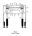
- FIG. 2 shows a cutting station 5 with a complete cutting tool 4 in the production direction P in the open position according to the prior art.
- Both an upper tool part 24 and a vertically movable lower tool part 25 are connected to guides 26.
- two guides 26 are arranged on both sides between the machine frame 6 and the transport chains 23.
- the transport chains 23 hold on both sides the first web-shaped material 8 with the shaped container 14 and the second web-shaped material 10.
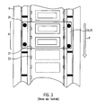
- a chain guide 27 and the transport chains 23 guided by it must be in the region A of the cutting station 5 (see FIG. 3 ) get extended. This is associated with considerable work and occurring downtime of the packaging machine 1.
- FIG. 4 shows a region B at the end of the packaging machine 1 according to the invention, in which the chain guide 27 is no longer attached to the machine frame 6, but is carried out crragend in the direction of production P.
- the machine frame 6 ends already before the region B of the cutting station 5.
- the cutting station 5 is designed in the example shown so that two packages 21 are cut simultaneously.
- Each two guides 26 are attached to both sides of a frame 29. Both the frame 29, as well as the guides 26 are located outside the chain guides 27 for the transport chains 23.
- the transport chains 23 are on End of the chain guide 27 deflected by pulleys 28, wherein the upper or leading chain center (with the clamped first web-like material) and the lower or trailing chain center (without first sheet-like material) in the region B parallel.
- FIG. 5 shows the area B as a sectional view in the production direction P.
- the frame 29 of the cutting station 5 is not connected to the machine frame 6, but stands independently on the ground and is by means of actuators 30 and independently of the machine frame 6 erectable and alignable.
- the chain guides 27 and the feed chains 23 are arranged on the one hand between the guides 26 and on the other hand between the upper tool part 24 and the lower tool part 25th
- This embodiment allows the outward movement of the complete cutting tool 4, for example, with the guides 26, in the direction of production P out of the packaging machine 1, as in FIG. 6 shown, since no fasteners of the chain guide 27 to the machine frame 6 in this area B hinder this movement.
- a tool change carriage can be pushed against the production direction P at the rear into the packaging machine 1 in order to pick up the usually very heavy complete cutting tool 4 and to drive it out of the packaging machine 1.
- Fixing elements 31 on the frame 29 ensure that after a change of the complete cutting tool 4, this can be repositioned exactly to the frame 29 and the packaging machine 1.
Landscapes
- Engineering & Computer Science (AREA)
- Mechanical Engineering (AREA)
- Life Sciences & Earth Sciences (AREA)
- Forests & Forestry (AREA)
- Auxiliary Devices For And Details Of Packaging Control (AREA)
- Containers And Plastic Fillers For Packaging (AREA)
Abstract
Description
- Die Erfindung bezieht sich auf eine Tiefziehverpackungsmaschine gemäß dem Oberbegriff des Anspruchs 1.
- Bekannte Tiefziehverpackungsmaschinen der Anmelderin weisen Schneidstationen mit Komplettschnittwerkzeugen auf. Kennzeichnend für ein Komplettschnittwerkzeug, das auch als Formschnittwerkzeug bezeichnet wird, ist, dass damit eine Verpackung mit nur einer Schneidbewegung aus dem Folienverbund ausgeschnitten, wobei das Schneidmesser die Außenkontur der Verpackung aufweist. Dabei sind Führungssäulen, die zur Aufnahme eines oberen Schneidwerkzeugs und eines bewegbaren unteren Schneidwerkzeuges notwendig sind, jeweils beidseitig zwischen der Kettenführung zur Führung der Klammerkette, der Klammerkette selbst und dem Maschinenrahmen angeordnet. Zu Wartungszecken oder zum Austausch des Komplettschnittwerkzeugs beispielsweise bei einem Formatwechsel werden das obere und das untere Schneidwerkzeug (sowie die Führungssäulen) nach oben aus der Tiefziehverpackungsmaschine entnommen. Hierzu müssen im Bereich der Schneidstation an beiden Seiten die Klammerkette und die Kettenführung entfernt werden. Dies bedingt einen besonderen hohen und zeitintensiven Montageaufwand und lange Stillstandszeiten der Tiefziehverpackungsmaschine.
- Aufgabe der erfindungsgemäßen Tiefziehverpackungsmaschine ist es, einen Wechsel eines Komplettschnittwerkzeugs zu vereinfachen.
- Diese Aufgabe wird gelöst durch eine Tiefziehverpackungsmaschine mit den Merkmalen des Anspruchs 1. Vorteilhafte Weiterbildungen der Erfindung sind in den Unteransprüchen angegeben.
- Die erfindungsgemäße Tiefziehverpackungsmaschine umfasst Kettenführungen für die Folienvorschubketten, eine Formstation, eine Siegelstation und eine Schneidstation, wobei die Schneidstation ein Komplettschnittwerkzeug aufweist. Die Tiefziehverpackungsmaschine ist so gestaltet, dass das Komplettschnittwerkzeug in Produktionsrichtung aus der Tiefziehverpackungsmaschine herausnehmbar ist. Somit müssen die Folienvorschubketten und die Kettenführungen im Bereich der Schneidstation nicht demontiert werden und das Komplettschnittwerkzeug kann als eine Einheit zum Ende der Tiefziehverpackungsmaschine hin entnommen werden. Dies führt zu minimalen Stillstandszeiten beim Wechsel von Komplettschnittwerkzeugen. Das Komplettschnittwerkzeug kann auch als eine Streifenstanze ausgebildet sein.
- Das Komplettschnittwerkzeug umfasst ein Werkzeugoberteil, ein Werkzeugunterteil und Führungen, auf denen das Werkzeugoberteil und das Werkzeugunterteil bewegt werden.
- Vorzugsweise sind die Kettenführungen im Bereich der Schneidstation in Produktionsrichtung zum Ende der Tiefziehverpackungsmaschine hin freiragend angeordnet. Diese fliegende Lagerung führt dazu, dass das Komplettschnittwerkzeug in Produktionsrichtung zum Herausbewegen nicht durch Störkanten oder Befestigungsmittel der beidseitig vorhandenen Kettenführungen behindert wird.
- Bevorzugt ist am Ende der beidseitig in Produktionsrichtung vorgesehenen Kettenführungen jeweils ein Umlenkrad vorgesehen, um eine in Vertikalrichtung schmale Bauform der Kettenführungen zu ermöglichen und den Raumbedarf der Kettenführungen innerhalb des Komplettschnittwerkzeugs auf ein Minimum zu reduzieren.
- Vorteilhaft ist, wenn sowohl ein oberes bzw. vorlaufendes Kettentrum der Folienvorschubketten als auch ein unteres bzw. nachlaufendes Kettentrum im Bereich der Schneidstation innerhalb des Komplettschnittwerkzeugs angeordnet sind, um eine konstruktiv einfache und kompakte Bauform der Kettenführung im Bereich der Schneidstation und darüber hinaus zu ermöglichen.
- Ein in Produktionsrichtung hinteres Ende eines Maschinenrahmens ist in Produktionsrichtung vor der Schneidstation vorgesehen und ermöglicht somit eine Anordnung der Führungssäulen des Komplettschnittwerkzeugs und des Gestells für die Schneidstation außerhalb und nahe der Kettenführungen.
- Vorzugsweise sind alle vertikalen Führungssäulen des Komplettschnittwerkzeugs außerhalb der Kettenführung angeordnet.
- Das Komplettschnittwerkzeug umfasst ein Schneidwerkzeugoberteil, ein Schneidwerkzeugunterteil und mindestens zwei Führungssäulen, die die Schneidwerkzeuge verbinden, wobei das Schneidwerkzeugunterteil eine vertikale Hubbewegung daran ausführt. Vorzugsweise sind die Kettenführungen einerseits zwischen dem Werkzeugunterteil und dem Werkzeugoberteil und andererseits zwischen den Führungssäulen quer zur Produktionsrichtung vorgesehen.
- Bevorzugt ist die Tiefziehverpackungsmaschine so gestaltet, dass ein Werkzeugwechselwagen zur Aufnahme des Komplettschnittwerkzeugs entgegen der Produktionsrichtung in die Tiefziehverpackungsmaschine einfahrbar ist. Dies ist besonders bei größeren Komplettschnittwerkzeugen vorteilhaft, da das Gewicht für das Herausnehmen durch das Bedienpersonal oder einen Servicetechniker zu groß ist und ein Werkzeugwagen aus ergonomischer Sicht eine einfache und sichere Handhabung beim Werkzeugwechsel gewährt.
- Bevorzugt sind Fixierelemente an der Schneidstation vorgesehen, um das Komplettschnittwerkzeug in der Schneidstation wiederholgenau zu positionieren, um nach einem Wechsel neue zusätzliche und aufwendige Einstell- bzw. Ausrichttätigkeiten zu vermeiden.
- Die Schneidstation weist vorzugsweise Stellelemente auf, um die Schneidstation unabhängig vom Maschinenrahmen aufzustellen und/oder auszurichten.
- Im Folgenden wird ein vorteilhaftes Ausführungsbeispiel der Erfindung anhand einer Zeichnung näher erläutert.
- Im Einzelnen zeigen:
- Figur 1
- eine schematische Ansicht einer Tiefziehverpackungsmaschine mit einem Komplettschnittwerkzeug,
- Figur 2
- eine Schnittansicht durch eine Schneidstation mit einem Komplettschnittwerkzeug in Produktionsrichtung nach Stand der Technik,
- Figur 3
- eine Draufsicht auf eine Schneidstation von
Figur 2 nach Stand der Technik, - Figur 4
- eine Draufsicht auf eine Schneidstation einer erfindungsgemäßen Tiefziehverpackungsmaschine,
- Figur 5
- eine Schnittansicht durch eine Schneidstation mit einem Komplettschnittwerkzeug einer erfindungsgemäßen Tiefziehverpackungsmaschine in Produktionsrichtung,
- Figur 6
- eine Draufsicht auf die Schneidstation von
Figur 4 mit herausbewegtem Komplettschnittwerkzeug. - Gleiche Komponenten sind in den Figuren durchgängig mit gleichen Bezugszeichen versehen.
-
Figur 1 zeigt in schematischer Ansicht eine Verpackungsmaschine 1 in Form einer Tiefziehverpackungsmaschine. Diese Tiefziehverpackungsmaschine 1 weist eine Formstation 2, eine Siegelstation 3, eine Schneideinrichtung 5 auf, die in dieser Reihenfolge in eine Produktionsrichtung P an einem Maschinenrahmen 6 angeordnet sind. - Eingangsseitig befindet sich an dem Maschinenrahmen 6 eine Zufuhrrolle 7, von der ein erstes bahnförmiges Material 8 abgezogen wird. Im Bereich der Siegelstation 3 ist ein Materialspeicher 9 vorgesehen, von dem ein zweites bahnförmiges Material 10 als Deckelfolie abgezogen wird. Ferner weist die Verpackungsmaschine 1 eine nicht dargestellte Vorschubeinrichtung auf, die das erste bahnförmige Material 8 ergreift und in einem Hauptarbeitstakt taktweise in der Arbeitsrichtung R weitertransportiert. Die Vorschubeinrichtung kann zum Beispiel durch seitlich angeordnete Klammer- oder Transportketten 23 (siehe
Figur 2 ) realisiert sein. - In der dargestellten Ausführungsform ist die Formstation 2 als eine Tiefziehstation ausgebildet, in der in dem ersten bahnförmigen Material 8 durch Tiefziehen Behälter 14 geformt werden. Dabei kann die Formstation 2 derart ausgebildet sein, dass in der Richtung senkrecht zur Arbeitsrichtung R mehrere Behälter nebeneinander gebildet werden. In Arbeitsrichtung R hinter der Formstation 2 ist eine Einlegestrecke 15 vorgesehen, in der die in dem ersten bahnförmigen Material 8 geformten Behälter 14 mit Produkt 16 befüllt werden. Die Siegelstation 3 verfügt über eine verschließbare Kammer 17, in der die Atmosphäre in den Behälter 14 vor dem Versiegeln zum Beispiel durch Gasspülen mit einem Austauschgas oder mit einem Austausch-Gasgemisch ersetzt werden kann und anschließend mit dem zweiten bahnförmigen Material 10 verschlossen wird. Die Schneidstation 5 weist ein Komplettschnittwerkzeug 4 auf. Eine Greifvorrichtung 20 ist dafür vorgesehen, vereinzelte geschnittene Verpackungen 21 aus der Schneidstation zu entnehmen und an ein nicht näher dargestelltes, neben der Tiefziehverpackungsmaschine 1 angeordnetes Abführband zu übergeben.
-
Figur 2 zeigt eine Schneidstation 5 mit einem Komplettschnittwerkzeug 4 in Produktionsrichtung P in geöffneter Stellung nach dem Stand der Technik. Sowohl ein Werkzeugoberteil 24, als auch ein vertikal bewegbares Werkzeugunterteil 25 sind mit Führungen 26 verbunden. Von den vier Führungen 26 sind jeweils zwei Führungen 26 beidseitig zwischen dem Maschinenrahmen 6 und den Transportketten 23 angeordnet. Die Transportketten 23 halten beidseitig das erste bahnförmige Material 8 mit dem geformten Behälter 14 und dem zweiten bahnförmigen Material 10. - Um ein Werkzeug unterteil 25 beispielsweise zur Wartung oder bei einem Formatwechsel ausbauen bzw. austauschen zu können, müssen eine Kettenführung 27 und die von ihr geführten Transportketten 23 in dem Bereich A der Schneidstation 5 (siehe
Figur 3 ) ausgebaut werden. Dies ist mit erheblichem Arbeitsaufwand und auftretenden Stillstandszeiten der Verpackungsmaschine 1 verbunden. -
Figur 4 zeigt einen Bereich B am Ende der erfindungsgemäßen Verpackungsmaschine 1, bei dem die Kettenführung 27 nicht mehr am Maschinenrahmen 6 angebracht ist, sondern freiragend in Produktionsrichtung P ausgeführt ist. Der Maschinenrahmen 6 endet bereits vor dem Bereich B der Schneidstation 5. Die Schneidstation 5 ist in dem gezeigten Beispiel so ausgestaltet, dass zwei Verpackungen 21 gleichzeitig geschnitten werden. Je zwei Führungen 26 sind beidseitig an einem Rahmen 29 befestigt. Sowohl der Rahmen 29, als auch die Führungen 26 befinden sich außerhalb der Kettenführungen 27 für die Transportketten 23. Die Transportketten 23 werden am Ende der Kettenführung 27 über Umlenkrollen 28 umgelenkt, wobei das obere bzw. vorlaufende Kettentrum (mit dem eingespannten ersten bahnförmigen Material) und das untere bzw. nachlaufende Kettentrum (ohne erstes bahnförmiges Material) in dem Bereich B parallel verlaufen. -
Figur 5 zeigt den Bereich B als Schnittansicht in Produktionsrichtung P. Der Rahmen 29 der Schneistation 5 ist dabei nicht mit dem Maschinenrahmen 6 verbunden, sondern steht eigenständig auf dem Boden und ist mittels Stellelementen 30 auch unabhängig vom Maschinenrahmen 6 aufstellbar und dazu ausrichtbar. Dabei sind die Kettenführungen 27 und die Vorschubketten 23 einerseits zwischen den Führungen 26 angeordnet und andererseits zwischen dem Werkzeugoberteil 24 und dem Werkzeugunterteil 25. - Diese Ausführung ermöglicht das Herausbewegung des Komplettschnittwerkzeugs 4, beispielsweise auch mit den Führungen 26, in Produktionsrichtung P heraus der Verpackungsmaschine 1, wie in
Figur 6 dargestellt, da keine Befestigungselemente von der Kettenführung 27 an den Maschinenrahmen 6 in diesem Bereich B diese Bewegung behindern. Als ergonomische Erleichterung kann sogar ein Werkzeugwechselwagen entgegen der Produktionsrichtung P hinten in die Verpackungsmaschine 1 eingeschoben werden, um das meist sehr schwere Komplettschnittwerkzeug 4 aufzunehmen und aus der Verpackungsmaschine 1 herauszufahren. Fixierelemente 31 am Rahmen 29 stellen sicher, dass nach einem Wechsel des Komplettschnittwerkzeugs 4 dieses wiederholgenau zum Rahmen 29 und zur Verpackungsmaschine 1 positioniert werden kann.
Claims (10)
- Tiefziehverpackungsmaschine (1) umfassend Kettenführungen (27) zum Führen einer Transportkette (23) für ein bahnförmiges Material (8) und eine Schneidstation (5), wobei die Schneidstation (5) ein Komplettschnittwerkzeug (4) aufweist, dadurch gekennzeichnet, dass das Komplettschnittwerkzeug (4) in Produktionsrichtung (P) aus der Tiefziehverpackungsmaschine (1) herausnehmbar ist.
- Tiefziehverpackungsmaschine nach Anspruch 1, dadurch gekennzeichnet, dass die Kettenführungen (27) im Bereich (B) der Schneidstation (5) in Produktionsrichtung (P) zum Ende der Tiefziehverpackungsmaschine (1) hin freiragend angeordnet sind.
- Tiefziehverpackungsmaschine nach einem der vorangehenden Ansprüche, dadurch gekennzeichnet, dass am Ende der beidseitig in Produktionsrichtung (P) vorgesehen Kettenführungen (27) jeweils ein Kettenumlenkrad (28) vorgesehen ist.
- Tiefziehverpackungsmaschine nach einem der vorangehenden Ansprüche, dadurch gekennzeichnet, dass sowohl ein oberes Kettentrum als auch ein unteres Kettentrum im Bereich (B) der Schneidstation (5) innerhalb des Komplettschnittwerkzeugs (4) angeordnet sind.
- Tiefziehverpackungsmaschine nach Anspruch 1, dadurch gekennzeichnet, dass ein in Produktionsrichtung (P) befindliches Ende eines Maschinenrahmens (6) in Produktionsrichtung (P) vor der Schneidstation (5) vorgesehen ist.
- Tiefziehverpackungsmaschine nach einem der vorangehenden Ansprüche, dadurch gekennzeichnet, dass alle vertikalen Führungssäulen (26) des Komplettschnittwerkzeugs (4) außerhalb der Kettenführungen (27) angeordnet sind.
- Tiefziehverpackungsmaschine nach einem der vorangehenden Ansprüche, dadurch gekennzeichnet, dass das Komplettschnittwerkzeug (4) ein Schneidwerkzeugoberteil (24), ein Schneidwerkzeugunterteil (25) und mindestens zwei Führungssäulen (26) umfasst, wobei die Kettenführungen (27) einerseits zwischen dem Werkzeugunterteil (25) und dem Werkzeugoberteil (24) und andererseits zwischen den Führungssäulen (26) quer zur Produktionsrichtung (P) vorgesehen sind.
- Tiefziehverpackungsmaschine nach einem der vorangehenden Ansprüche, dadurch gekennzeichnet, dass ein Werkzeugwechselwagen zur Aufnahme des Komplettschnittwerkzeugs (4) in die Tiefziehverpackungsmaschine (1) entgegen der Produktionsrichtung (P) einfahrbar ist.
- Tiefziehverpackungsmaschine nach einem der vorangehenden Ansprüche, dadurch gekennzeichnet, dass Fixierelemente (31) an der Schneidstation (5) vorgesehen sind, um das Komplettschnittwerkzeug (4) in der Schneidstation (5) wiederholgenau zu positionieren.
- Tiefziehverpackungsmaschine nach einem der vorangehenden Ansprüche, dadurch gekennzeichnet, dass die Schneidstation (5) Stellelemente (30) aufweist, um die Schneidstation (5) unabhängig vom Maschinenrahmen (6) aufzustellen und/oder auszurichten.
Applications Claiming Priority (1)
| Application Number | Priority Date | Filing Date | Title |
|---|---|---|---|
| DE102011100784A DE102011100784A1 (de) | 2011-05-06 | 2011-05-06 | Schneidstation mit Komplettschnittwerkzeug |
Publications (2)
| Publication Number | Publication Date |
|---|---|
| EP2520500A1 true EP2520500A1 (de) | 2012-11-07 |
| EP2520500B1 EP2520500B1 (de) | 2015-09-30 |
Family
ID=46149115
Family Applications (1)
| Application Number | Title | Priority Date | Filing Date |
|---|---|---|---|
| EP12003140.6A Active EP2520500B1 (de) | 2011-05-06 | 2012-05-02 | Schneidstation mit Komplettschnittwerkzeug |
Country Status (5)
| Country | Link |
|---|---|
| US (1) | US9580193B2 (de) |
| EP (1) | EP2520500B1 (de) |
| CN (1) | CN102774541A (de) |
| DE (1) | DE102011100784A1 (de) |
| ES (1) | ES2551416T3 (de) |
Families Citing this family (12)
| Publication number | Priority date | Publication date | Assignee | Title |
|---|---|---|---|---|
| DE102011115881B4 (de) * | 2011-10-12 | 2014-11-20 | Multivac Sepp Haggenmüller Gmbh & Co. Kg | Tiefziehverpackungsmaschine mit einseitiger Folienvorschubeinrichtung |
| US20230067693A1 (en) * | 2013-01-11 | 2023-03-02 | Vicon Machinery, Llc | Device and method for cutting insulation |
| CN103612418A (zh) * | 2013-11-20 | 2014-03-05 | 无锡鼎茂机械制造有限公司 | 制袋机的挡料装置 |
| DE102016103127A1 (de) * | 2015-03-02 | 2016-09-08 | Petratto S.R.L. | Verfahren zur Bearbeitung eines Blattes mittels einer automatischen Presse und automatische Presse |
| EP3428079B1 (de) * | 2017-07-14 | 2019-12-25 | MULTIVAC Sepp Haggenmüller SE & Co. KG | Tiefziehverpackungsmaschine mit flexibler packungsunterstützung |
| CN108482745B (zh) * | 2018-05-07 | 2024-03-26 | 汕头市甜甜乐糖果食品有限公司 | 一种封口膜对正准确、平整度高的包装杯封口装置 |
| JP6570699B2 (ja) * | 2018-05-25 | 2019-09-04 | マルホ発條工業株式会社 | 錠剤包装装置 |
| CN110329610B (zh) * | 2019-07-13 | 2021-05-28 | 山东叶之梦智能科技有限公司 | 一种纸尿裤自动包装机的封切包装系统 |
| EP3888863A1 (de) * | 2020-03-31 | 2021-10-06 | A O Schallinox GmbH | Schneidevorrichtung |
| DE102021126069A1 (de) | 2021-10-07 | 2023-04-13 | Multivac Sepp Haggenmüller Se & Co. Kg | Tiefziehverpackungsmaschine mit einer kettenführungsvorrichtung |
| CN114571793B (zh) * | 2022-05-05 | 2022-07-15 | 蓝海睿创科技(山东)有限责任公司 | 一种纸箱加工用的智能化水墨印刷机 |
| DE102023108015A1 (de) | 2023-03-29 | 2024-10-02 | Multivac Sepp Haggenmüller Se & Co. Kg | Tiefziehverpackungsmaschine mit einer Schneidstation und Verfahren zum Herausnehmen eines Schneidwerkzeugs einer Tiefziehverpackungsmaschine |
Citations (3)
| Publication number | Priority date | Publication date | Assignee | Title |
|---|---|---|---|---|
| DE3118946A1 (de) * | 1981-05-13 | 1982-12-16 | Krämer + Grebe GmbH & Co KG Maschinenfabrik, 3560 Biedenkopf | Vorrichtung zum austrennen von muldenfoermig tiefgezogenen, befuellten kunststoff-packungen aus den folienbahnen |
| WO2001028865A1 (en) * | 1999-10-20 | 2001-04-26 | S.P.C. Limited | Cutting assembly and seal integrity monitoring system for a filling and heat sealing line |
| WO2010064125A2 (en) * | 2008-12-03 | 2010-06-10 | Soremartec S.A. | Plant for packaging confectionary products in a sterile manner |
Family Cites Families (10)
| Publication number | Priority date | Publication date | Assignee | Title |
|---|---|---|---|---|
| US3216491A (en) * | 1963-10-28 | 1965-11-09 | Brown Machine Co Of Michigan | Plastic sheet conveying apparatus |
| US3685251A (en) * | 1970-03-26 | 1972-08-22 | Mahaffy & Harder Eng Co | Automatic packaging apparatus with improved means for cutting and contour trimming of packages |
| US4297929A (en) * | 1979-12-20 | 1981-11-03 | Liqui-Box Corporation | Separator and feeder for a strip of flexible bags |
| US5074143A (en) * | 1989-12-14 | 1991-12-24 | Alpha Industries, Inc. | Cart for removing and installing dies in a cut-off press |
| US5040403A (en) * | 1990-10-31 | 1991-08-20 | Chrysler Corporation | Method of changing stamping die sets |
| DE9113290U1 (de) * | 1991-10-25 | 1991-12-19 | Krämer + Grebe GmbH & Co KG Maschinenfabrik, 3560 Biedenkopf | Vorrichtung zum Herstellen einer Verpackung |
| IT1262791B (it) * | 1993-05-11 | 1996-07-04 | Isap Omv Group Spa | Metodo di sostituzione degli stampi in un'apparecchio di termoformatura di oggetti a partire da nastro di materiale termoplastico |
| NL1015973C2 (nl) | 2000-08-21 | 2002-02-25 | Fountain Tech Bv | Stansinrichting, in het bijzonder geschikt voor het vormen van labels en dergelijke folieelementen. |
| ATE409644T1 (de) | 2005-04-19 | 2008-10-15 | Multivac Haggenmueller Gmbh | Verpackungsmaschine |
| DE102005039673B4 (de) * | 2005-04-19 | 2013-12-19 | Gerhard Schubert Gmbh | Verfahren und Vorrichtung zum Herstellen von befüllten und dicht versiegelten Kunststoff-Tiefziehbehältern |
-
2011
- 2011-05-06 DE DE102011100784A patent/DE102011100784A1/de not_active Ceased
-
2012
- 2012-05-02 ES ES12003140.6T patent/ES2551416T3/es active Active
- 2012-05-02 EP EP12003140.6A patent/EP2520500B1/de active Active
- 2012-05-04 US US13/463,866 patent/US9580193B2/en not_active Expired - Fee Related
- 2012-05-07 CN CN2012101392129A patent/CN102774541A/zh active Pending
Patent Citations (3)
| Publication number | Priority date | Publication date | Assignee | Title |
|---|---|---|---|---|
| DE3118946A1 (de) * | 1981-05-13 | 1982-12-16 | Krämer + Grebe GmbH & Co KG Maschinenfabrik, 3560 Biedenkopf | Vorrichtung zum austrennen von muldenfoermig tiefgezogenen, befuellten kunststoff-packungen aus den folienbahnen |
| WO2001028865A1 (en) * | 1999-10-20 | 2001-04-26 | S.P.C. Limited | Cutting assembly and seal integrity monitoring system for a filling and heat sealing line |
| WO2010064125A2 (en) * | 2008-12-03 | 2010-06-10 | Soremartec S.A. | Plant for packaging confectionary products in a sterile manner |
Also Published As
| Publication number | Publication date |
|---|---|
| US9580193B2 (en) | 2017-02-28 |
| ES2551416T3 (es) | 2015-11-18 |
| EP2520500B1 (de) | 2015-09-30 |
| US20120283083A1 (en) | 2012-11-08 |
| DE102011100784A1 (de) | 2012-11-08 |
| CN102774541A (zh) | 2012-11-14 |
Similar Documents
| Publication | Publication Date | Title |
|---|---|---|
| EP2520500B1 (de) | Schneidstation mit Komplettschnittwerkzeug | |
| DE102011101053B4 (de) | Arbeitsstation für eine Verpackungsmaschine und Verfahren zum Werkzeugwechsel | |
| AT514929B1 (de) | Werkzeugrüstsystem für Biegepresse | |
| EP3468730B1 (de) | Be- und entladevorrichtung für eine maschine, maschine zum bearbeiten von plattenförmigen werkstücken sowie verfahren zum be- und entladen einer solchen maschine | |
| EP0847949A1 (de) | Einrichtung zur Bildung eines sich senkrecht zu den stehend aneinandergereihten Druckbogen erstreckenden Stapels | |
| EP0946389A1 (de) | Vorrichtung zum handhaben von gegenständen | |
| CH679219A5 (de) | ||
| EP2452790A1 (de) | Bearbeitungsstation für eine Stanzmaschine und Verfahren zur Probebogenauslage | |
| DE202013104432U1 (de) | Maschine zum Falten und Kleben von Zuschnitten für die Herstellung von Faltschachteln | |
| DE10353351A1 (de) | Roboter und Verfahren zum Umsetzen von Kartonagenstapeln | |
| DE102018113490A1 (de) | Schneidkopf und Schneidmaschine mit einem Schneidkopf | |
| EP3566985B1 (de) | Trayabstapelvorrichtung mit entlastungseinrichtung | |
| DE3716666C2 (de) | Plattenaufteilanlage mit einer Längssäge und einer Quersäge | |
| DE102015113350A1 (de) | Umreifungsvorrichtung für Packstücke und Verfahren zum Umreifen | |
| EP2146900B1 (de) | Umreifungsmaschine | |
| EP2418163B1 (de) | Ladevorrichtung für Blattstapel | |
| EP3715009B1 (de) | Verfahren zum herstellen von bewehrungsmatten | |
| EP1975074B1 (de) | Vorrichtung und Verfahren zum Be- und Entladen von einer Mehrzahl in einem oben offenen Aufnahmebehältnis angeordneter Gegenstände | |
| DE19914580A1 (de) | Verfahren zum Handhaben von Stapeln von Papier, Pappe o. dgl. an einer Schneidmaschine | |
| EP2933197A1 (de) | Vorrichtung zum abpacken von tuben oder dosen | |
| EP2711116A1 (de) | Druckbalken für eine Sägevorrichtung | |
| AT408879B (de) | Vorrichtung zum seitlichen auseinanderbewegen von plattenförmigen werkstücken | |
| DE102006045477A1 (de) | Arbeitsstation für eine Tiefziehmaschine | |
| DE3402497C2 (de) | Vorrichtung zum Kappen von Hölzern und zum anschließenden Bearbeiten der Holzabschnitte an den Seitenkanten | |
| DE202015104275U1 (de) | Umreifungsvorrichtung für Packstücke |
Legal Events
| Date | Code | Title | Description |
|---|---|---|---|
| PUAI | Public reference made under article 153(3) epc to a published international application that has entered the european phase |
Free format text: ORIGINAL CODE: 0009012 |
|
| AK | Designated contracting states |
Kind code of ref document: A1 Designated state(s): AL AT BE BG CH CY CZ DE DK EE ES FI FR GB GR HR HU IE IS IT LI LT LU LV MC MK MT NL NO PL PT RO RS SE SI SK SM TR |
|
| AX | Request for extension of the european patent |
Extension state: BA ME |
|
| 17P | Request for examination filed |
Effective date: 20121204 |
|
| GRAP | Despatch of communication of intention to grant a patent |
Free format text: ORIGINAL CODE: EPIDOSNIGR1 |
|
| RIC1 | Information provided on ipc code assigned before grant |
Ipc: B65B 61/28 20060101ALN20150518BHEP Ipc: B65B 31/00 20060101ALN20150518BHEP Ipc: B65B 9/04 20060101AFI20150518BHEP Ipc: B65B 59/04 20060101ALI20150518BHEP Ipc: B65B 61/06 20060101ALI20150518BHEP |
|
| INTG | Intention to grant announced |
Effective date: 20150619 |
|
| GRAS | Grant fee paid |
Free format text: ORIGINAL CODE: EPIDOSNIGR3 |
|
| GRAA | (expected) grant |
Free format text: ORIGINAL CODE: 0009210 |
|
| AK | Designated contracting states |
Kind code of ref document: B1 Designated state(s): AL AT BE BG CH CY CZ DE DK EE ES FI FR GB GR HR HU IE IS IT LI LT LU LV MC MK MT NL NO PL PT RO RS SE SI SK SM TR |
|
| REG | Reference to a national code |
Ref country code: CH Ref legal event code: NV Representative=s name: BOVARD AG, CH Ref country code: CH Ref legal event code: EP Ref country code: GB Ref legal event code: FG4D Free format text: NOT ENGLISH |
|
| REG | Reference to a national code |
Ref country code: AT Ref legal event code: REF Ref document number: 752234 Country of ref document: AT Kind code of ref document: T Effective date: 20151015 |
|
| REG | Reference to a national code |
Ref country code: IE Ref legal event code: FG4D Free format text: LANGUAGE OF EP DOCUMENT: GERMAN |
|
| REG | Reference to a national code |
Ref country code: DE Ref legal event code: R096 Ref document number: 502012004715 Country of ref document: DE |
|
| REG | Reference to a national code |
Ref country code: ES Ref legal event code: FG2A Ref document number: 2551416 Country of ref document: ES Kind code of ref document: T3 Effective date: 20151118 |
|
| REG | Reference to a national code |
Ref country code: NL Ref legal event code: FP |
|
| PG25 | Lapsed in a contracting state [announced via postgrant information from national office to epo] |
Ref country code: GR Free format text: LAPSE BECAUSE OF FAILURE TO SUBMIT A TRANSLATION OF THE DESCRIPTION OR TO PAY THE FEE WITHIN THE PRESCRIBED TIME-LIMIT Effective date: 20151231 Ref country code: NO Free format text: LAPSE BECAUSE OF FAILURE TO SUBMIT A TRANSLATION OF THE DESCRIPTION OR TO PAY THE FEE WITHIN THE PRESCRIBED TIME-LIMIT Effective date: 20151230 Ref country code: LV Free format text: LAPSE BECAUSE OF FAILURE TO SUBMIT A TRANSLATION OF THE DESCRIPTION OR TO PAY THE FEE WITHIN THE PRESCRIBED TIME-LIMIT Effective date: 20150930 Ref country code: LT Free format text: LAPSE BECAUSE OF FAILURE TO SUBMIT A TRANSLATION OF THE DESCRIPTION OR TO PAY THE FEE WITHIN THE PRESCRIBED TIME-LIMIT Effective date: 20150930 Ref country code: FI Free format text: LAPSE BECAUSE OF FAILURE TO SUBMIT A TRANSLATION OF THE DESCRIPTION OR TO PAY THE FEE WITHIN THE PRESCRIBED TIME-LIMIT Effective date: 20150930 |
|
| REG | Reference to a national code |
Ref country code: LT Ref legal event code: MG4D |
|
| PG25 | Lapsed in a contracting state [announced via postgrant information from national office to epo] |
Ref country code: RS Free format text: LAPSE BECAUSE OF FAILURE TO SUBMIT A TRANSLATION OF THE DESCRIPTION OR TO PAY THE FEE WITHIN THE PRESCRIBED TIME-LIMIT Effective date: 20150930 Ref country code: SE Free format text: LAPSE BECAUSE OF FAILURE TO SUBMIT A TRANSLATION OF THE DESCRIPTION OR TO PAY THE FEE WITHIN THE PRESCRIBED TIME-LIMIT Effective date: 20150930 Ref country code: HR Free format text: LAPSE BECAUSE OF FAILURE TO SUBMIT A TRANSLATION OF THE DESCRIPTION OR TO PAY THE FEE WITHIN THE PRESCRIBED TIME-LIMIT Effective date: 20150930 |
|
| REG | Reference to a national code |
Ref country code: DE Ref legal event code: R082 Ref document number: 502012004715 Country of ref document: DE Representative=s name: GRUENECKER PATENT- UND RECHTSANWAELTE PARTG MB, DE Ref country code: DE Ref legal event code: R081 Ref document number: 502012004715 Country of ref document: DE Owner name: MULTIVAC SEPP HAGGENMUELLER SE & CO. KG, DE Free format text: FORMER OWNER: MULTIVAC SEPP HAGGENMUELLER GMBH & CO. KG, 87787 WOLFERTSCHWENDEN, DE |
|
| PG25 | Lapsed in a contracting state [announced via postgrant information from national office to epo] |
Ref country code: CZ Free format text: LAPSE BECAUSE OF FAILURE TO SUBMIT A TRANSLATION OF THE DESCRIPTION OR TO PAY THE FEE WITHIN THE PRESCRIBED TIME-LIMIT Effective date: 20150930 Ref country code: EE Free format text: LAPSE BECAUSE OF FAILURE TO SUBMIT A TRANSLATION OF THE DESCRIPTION OR TO PAY THE FEE WITHIN THE PRESCRIBED TIME-LIMIT Effective date: 20150930 Ref country code: SK Free format text: LAPSE BECAUSE OF FAILURE TO SUBMIT A TRANSLATION OF THE DESCRIPTION OR TO PAY THE FEE WITHIN THE PRESCRIBED TIME-LIMIT Effective date: 20150930 Ref country code: IS Free format text: LAPSE BECAUSE OF FAILURE TO SUBMIT A TRANSLATION OF THE DESCRIPTION OR TO PAY THE FEE WITHIN THE PRESCRIBED TIME-LIMIT Effective date: 20160130 |
|
| REG | Reference to a national code |
Ref country code: FR Ref legal event code: PLFP Year of fee payment: 5 |
|
| PG25 | Lapsed in a contracting state [announced via postgrant information from national office to epo] |
Ref country code: PL Free format text: LAPSE BECAUSE OF FAILURE TO SUBMIT A TRANSLATION OF THE DESCRIPTION OR TO PAY THE FEE WITHIN THE PRESCRIBED TIME-LIMIT Effective date: 20150930 Ref country code: PT Free format text: LAPSE BECAUSE OF FAILURE TO SUBMIT A TRANSLATION OF THE DESCRIPTION OR TO PAY THE FEE WITHIN THE PRESCRIBED TIME-LIMIT Effective date: 20160201 Ref country code: RO Free format text: LAPSE BECAUSE OF FAILURE TO SUBMIT A TRANSLATION OF THE DESCRIPTION OR TO PAY THE FEE WITHIN THE PRESCRIBED TIME-LIMIT Effective date: 20150930 |
|
| REG | Reference to a national code |
Ref country code: DE Ref legal event code: R097 Ref document number: 502012004715 Country of ref document: DE |
|
| PLBE | No opposition filed within time limit |
Free format text: ORIGINAL CODE: 0009261 |
|
| STAA | Information on the status of an ep patent application or granted ep patent |
Free format text: STATUS: NO OPPOSITION FILED WITHIN TIME LIMIT |
|
| PG25 | Lapsed in a contracting state [announced via postgrant information from national office to epo] |
Ref country code: DK Free format text: LAPSE BECAUSE OF FAILURE TO SUBMIT A TRANSLATION OF THE DESCRIPTION OR TO PAY THE FEE WITHIN THE PRESCRIBED TIME-LIMIT Effective date: 20150930 Ref country code: BE Free format text: LAPSE BECAUSE OF NON-PAYMENT OF DUE FEES Effective date: 20160531 |
|
| 26N | No opposition filed |
Effective date: 20160701 |
|
| PG25 | Lapsed in a contracting state [announced via postgrant information from national office to epo] |
Ref country code: SI Free format text: LAPSE BECAUSE OF FAILURE TO SUBMIT A TRANSLATION OF THE DESCRIPTION OR TO PAY THE FEE WITHIN THE PRESCRIBED TIME-LIMIT Effective date: 20150930 |
|
| PG25 | Lapsed in a contracting state [announced via postgrant information from national office to epo] |
Ref country code: LU Free format text: LAPSE BECAUSE OF FAILURE TO SUBMIT A TRANSLATION OF THE DESCRIPTION OR TO PAY THE FEE WITHIN THE PRESCRIBED TIME-LIMIT Effective date: 20160502 |
|
| GBPC | Gb: european patent ceased through non-payment of renewal fee |
Effective date: 20160502 |
|
| REG | Reference to a national code |
Ref country code: IE Ref legal event code: MM4A |
|
| REG | Reference to a national code |
Ref country code: FR Ref legal event code: PLFP Year of fee payment: 6 |
|
| PG25 | Lapsed in a contracting state [announced via postgrant information from national office to epo] |
Ref country code: IE Free format text: LAPSE BECAUSE OF NON-PAYMENT OF DUE FEES Effective date: 20160502 Ref country code: GB Free format text: LAPSE BECAUSE OF NON-PAYMENT OF DUE FEES Effective date: 20160502 |
|
| REG | Reference to a national code |
Ref country code: FR Ref legal event code: PLFP Year of fee payment: 7 |
|
| PG25 | Lapsed in a contracting state [announced via postgrant information from national office to epo] |
Ref country code: HU Free format text: LAPSE BECAUSE OF FAILURE TO SUBMIT A TRANSLATION OF THE DESCRIPTION OR TO PAY THE FEE WITHIN THE PRESCRIBED TIME-LIMIT; INVALID AB INITIO Effective date: 20120502 Ref country code: CY Free format text: LAPSE BECAUSE OF FAILURE TO SUBMIT A TRANSLATION OF THE DESCRIPTION OR TO PAY THE FEE WITHIN THE PRESCRIBED TIME-LIMIT Effective date: 20150930 Ref country code: SM Free format text: LAPSE BECAUSE OF FAILURE TO SUBMIT A TRANSLATION OF THE DESCRIPTION OR TO PAY THE FEE WITHIN THE PRESCRIBED TIME-LIMIT Effective date: 20150930 |
|
| PG25 | Lapsed in a contracting state [announced via postgrant information from national office to epo] |
Ref country code: MK Free format text: LAPSE BECAUSE OF FAILURE TO SUBMIT A TRANSLATION OF THE DESCRIPTION OR TO PAY THE FEE WITHIN THE PRESCRIBED TIME-LIMIT Effective date: 20150930 Ref country code: TR Free format text: LAPSE BECAUSE OF FAILURE TO SUBMIT A TRANSLATION OF THE DESCRIPTION OR TO PAY THE FEE WITHIN THE PRESCRIBED TIME-LIMIT Effective date: 20150930 Ref country code: MT Free format text: LAPSE BECAUSE OF FAILURE TO SUBMIT A TRANSLATION OF THE DESCRIPTION OR TO PAY THE FEE WITHIN THE PRESCRIBED TIME-LIMIT Effective date: 20150930 Ref country code: MC Free format text: LAPSE BECAUSE OF FAILURE TO SUBMIT A TRANSLATION OF THE DESCRIPTION OR TO PAY THE FEE WITHIN THE PRESCRIBED TIME-LIMIT Effective date: 20150930 |
|
| REG | Reference to a national code |
Ref country code: AT Ref legal event code: MM01 Ref document number: 752234 Country of ref document: AT Kind code of ref document: T Effective date: 20170502 |
|
| PG25 | Lapsed in a contracting state [announced via postgrant information from national office to epo] |
Ref country code: BG Free format text: LAPSE BECAUSE OF FAILURE TO SUBMIT A TRANSLATION OF THE DESCRIPTION OR TO PAY THE FEE WITHIN THE PRESCRIBED TIME-LIMIT Effective date: 20150930 |
|
| PG25 | Lapsed in a contracting state [announced via postgrant information from national office to epo] |
Ref country code: AT Free format text: LAPSE BECAUSE OF NON-PAYMENT OF DUE FEES Effective date: 20170502 |
|
| PG25 | Lapsed in a contracting state [announced via postgrant information from national office to epo] |
Ref country code: AL Free format text: LAPSE BECAUSE OF FAILURE TO SUBMIT A TRANSLATION OF THE DESCRIPTION OR TO PAY THE FEE WITHIN THE PRESCRIBED TIME-LIMIT Effective date: 20150930 |
|
| PGFP | Annual fee paid to national office [announced via postgrant information from national office to epo] |
Ref country code: FR Payment date: 20200519 Year of fee payment: 9 Ref country code: NL Payment date: 20200518 Year of fee payment: 9 Ref country code: CH Payment date: 20200522 Year of fee payment: 9 |
|
| PGFP | Annual fee paid to national office [announced via postgrant information from national office to epo] |
Ref country code: IT Payment date: 20200528 Year of fee payment: 9 |
|
| REG | Reference to a national code |
Ref country code: CH Ref legal event code: PL |
|
| REG | Reference to a national code |
Ref country code: NL Ref legal event code: MM Effective date: 20210601 |
|
| PG25 | Lapsed in a contracting state [announced via postgrant information from national office to epo] |
Ref country code: CH Free format text: LAPSE BECAUSE OF NON-PAYMENT OF DUE FEES Effective date: 20210531 Ref country code: LI Free format text: LAPSE BECAUSE OF NON-PAYMENT OF DUE FEES Effective date: 20210531 |
|
| PG25 | Lapsed in a contracting state [announced via postgrant information from national office to epo] |
Ref country code: NL Free format text: LAPSE BECAUSE OF NON-PAYMENT OF DUE FEES Effective date: 20210601 Ref country code: FR Free format text: LAPSE BECAUSE OF NON-PAYMENT OF DUE FEES Effective date: 20210531 |
|
| PG25 | Lapsed in a contracting state [announced via postgrant information from national office to epo] |
Ref country code: IT Free format text: LAPSE BECAUSE OF NON-PAYMENT OF DUE FEES Effective date: 20200502 |
|
| P01 | Opt-out of the competence of the unified patent court (upc) registered |
Effective date: 20230404 |
|
| PGFP | Annual fee paid to national office [announced via postgrant information from national office to epo] |
Ref country code: DE Payment date: 20250519 Year of fee payment: 14 |
|
| PGFP | Annual fee paid to national office [announced via postgrant information from national office to epo] |
Ref country code: ES Payment date: 20250616 Year of fee payment: 14 |
|
| PG25 | Lapsed in a contracting state [announced via postgrant information from national office to epo] |
Ref country code: IT Free format text: LAPSE BECAUSE OF NON-PAYMENT OF DUE FEES Effective date: 20210502 |