EP2515069B1 - Messinstrument für Oberflächenstrukturen - Google Patents
Messinstrument für Oberflächenstrukturen Download PDFInfo
- Publication number
- EP2515069B1 EP2515069B1 EP12002238.9A EP12002238A EP2515069B1 EP 2515069 B1 EP2515069 B1 EP 2515069B1 EP 12002238 A EP12002238 A EP 12002238A EP 2515069 B1 EP2515069 B1 EP 2515069B1
- Authority
- EP
- European Patent Office
- Prior art keywords
- measurement arm
- measurement
- plate
- seat
- arm
- Prior art date
- Legal status (The legal status is an assumption and is not a legal conclusion. Google has not performed a legal analysis and makes no representation as to the accuracy of the status listed.)
- Active
Links
Images






Classifications
-
- G—PHYSICS
- G01—MEASURING; TESTING
- G01B—MEASURING LENGTH, THICKNESS OR SIMILAR LINEAR DIMENSIONS; MEASURING ANGLES; MEASURING AREAS; MEASURING IRREGULARITIES OF SURFACES OR CONTOURS
- G01B5/00—Measuring arrangements characterised by the use of mechanical techniques
- G01B5/0011—Arrangements for eliminating or compensation of measuring errors due to temperature or weight
- G01B5/0016—Arrangements for eliminating or compensation of measuring errors due to temperature or weight due to weight
-
- G—PHYSICS
- G01—MEASURING; TESTING
- G01B—MEASURING LENGTH, THICKNESS OR SIMILAR LINEAR DIMENSIONS; MEASURING ANGLES; MEASURING AREAS; MEASURING IRREGULARITIES OF SURFACES OR CONTOURS
- G01B3/00—Measuring instruments characterised by the use of mechanical techniques
- G01B3/002—Details
- G01B3/008—Arrangements for controlling the measuring force
-
- G—PHYSICS
- G01—MEASURING; TESTING
- G01B—MEASURING LENGTH, THICKNESS OR SIMILAR LINEAR DIMENSIONS; MEASURING ANGLES; MEASURING AREAS; MEASURING IRREGULARITIES OF SURFACES OR CONTOURS
- G01B5/00—Measuring arrangements characterised by the use of mechanical techniques
- G01B5/004—Measuring arrangements characterised by the use of mechanical techniques for measuring coordinates of points
- G01B5/008—Measuring arrangements characterised by the use of mechanical techniques for measuring coordinates of points using coordinate measuring machines
- G01B5/012—Contact-making feeler heads therefor
- G01B5/016—Constructional details of contacts
-
- G—PHYSICS
- G01—MEASURING; TESTING
- G01B—MEASURING LENGTH, THICKNESS OR SIMILAR LINEAR DIMENSIONS; MEASURING ANGLES; MEASURING AREAS; MEASURING IRREGULARITIES OF SURFACES OR CONTOURS
- G01B5/00—Measuring arrangements characterised by the use of mechanical techniques
- G01B5/28—Measuring arrangements characterised by the use of mechanical techniques for measuring roughness or irregularity of surfaces
Definitions
- the present invention relates to a surface texture measuring instrument. Specifically, the present invention relates to a surface texture measuring instrument including an exchangeable measurement arm having a stylus to be brought into contact with a surface of an object to be measured.
- a surface texture measuring instrument that measures a surface texture such as a surface profile and surface roughness of an object by moving a stylus along a surface of an object to be measured while being in contact with the surface, detecting the displacement of the stylus (in a direction perpendicular to a moving direction of the stylus) caused by the surface profile or surface roughness of the object, and measuring the surface texture based on the displacement of the stylus.
- Some of the surface texture measuring instrument include styluses (measurement arms) having various profiles prepared in advance and exchanged depending on profiles of measurement portions, so that measurement portions of an object having various profiles can be measured by the most suitable stylus for the profiles of the measurement portions.
- Patent Literature 1 ( DE 19617022C1 ) has proposed a contour measuring instrument including: a column standing upright on a base; a holder provided on the column to be vertically movable via an adjustment instrument; a housing provided to the holder; a see-saw provided in the housing to be horizontally movable via a linear motor; a measurement arm connected to the see-saw via a connecting unit outside the housing; and a stylus provided at an end of the measurement arm, in which the measurement arm is exchangeable outside the housing.
- the measurement arm is exchangeable outside the housing. Accordingly, although exchange of the measurement arm is easy, an error is likely to be caused because a detector detecting displacement of the measurement arm including the stylus to be brought into contact with an object is offset from an axis of the measurement arm and the stylus.
- the connecting unit provided with a detachable measurement arm is disposed outside the housing, when external force acts on the measurement arm and the stylus to detach the measurement arm from the connecting unit, the measurement arm is likely to fall. In such a case, the measurement arm and the stylus may be damaged. Furthermore, since the connecting unit is exposed outside the housing, the connecting unit may interfere with the object in measurement to be damaged and easily becomes dirty depending on external environment in which the connecting unit is used.
- the surface texture measuring instrument such as the aforementioned contour measuring instrument, it is required to adjust pressure (i.e., measurement force), by which the stylus is brought into contact with the surface of the object, to the most suitable measurement force for a material and a profile of the object.
- pressure i.e., measurement force
- a measuring force adjusting mechanism needs to be adjusted after the exchange of the measurement arm.
- the stylus at the end of the measurement arm is put on a measuring instrument for measuring force (e.g., an electronic scale), and while keeping this condition, the measuring force adjusting mechanism is adjusted such that a value displayed on the measuring instrument is 0.
- a measuring instrument for measuring force e.g., an electronic scale
- US 2003/0117633 A1 discloses a measuring device having a probe arm which is held, as a detachable probe-arm segment, to a carrier which is permanently mounted to the measuring device, wherein a magnetic probe-arm holder serves in seating the probe arm on the carrier.
- US 5 517 307 A discloses an apparatus for surface measurement having a grating interferometer with a curved diffraction grating carried on a pivotal support arm of a probe for contacting a surface.
- the probe is biased into contact with a surface by an electromagnetic coil acting on an armature, or a pair of such biasing arrangements.
- the probe is provided near one end of the support arm, mounted by a pivot bearing to a pickup body assembly solid with a carriage.
- US 2005/033551 A1 discloses a measuring apparatus having a measuring head, wherein the measuring head has a pair of arm members which are supported on a supporting member so as to be rotatable on the supporting member, a pair of probes which are respectively attached to ends of the corresponding arm members, and which contact a work, urging members which act on the arm members to urge the probes toward the work, and each of which is formed of a compression spring, and a pair of detectors each having a scale fixed on an end surface of the arm member opposite from the probe as seen from the supporting member, the detector also having a reading head fixed on a head body.
- US 6 295 866 B1 discloses a surface-tracking measuring machine having a frame, a probe swingably supported by the frame and having a tracer at an end thereof, a measuring force controller for controlling the measuring force applied to the probe, a displacement detector for detecting a displacement of the probe, a measuring force detector for detecting the measuring force applied to the probe, and a controller for comparing a measuring force detected value detected by the measuring force detector and a previously commanded measuring force command value and to control the measuring force controller so that the measuring force detected value is equal to the measuring force command value.
- US 6 209 217 B1 discloses a surface-following type measuring machine having a main body disposed for movement relative to an object to be measured.
- a measuring arm is supported by the main body for displacement relative thereto, and carries at one end thereof a stylus holder and a stylus in a manner permitting replacement of the stylus holder and the stylus. Displacement of the measuring arm is detected by a displacement detecting device.
- An object of the invention is to provide a surface texture measuring instrument to solve the above problem which is highly accurate and capable of reducing dirtiness and damage of a stylus, a measurement arm and the like, and is expected to improve usability and operational efficiency by automatically adjusting balance of the measurement arm even when the measurement arm is exchanged.
- a surface texture measuring instrument comprising: a measurement arm that is supported by a body movably in a circular movement around a rotary shaft; a stylus provided at an end of the measurement arm; a displacement detector that detects a circular movement amount of the measurement arm; a detector having a casing that houses the body; a stage on which an object to be measured is mounted; and a relative movement mechanism that moves the detector and the stage relatively to each other, the surface texture measuring instrument being configured to detect the circular movement amount of the measurement arm by the displacement detector while moving the detector and the stage relatively to each other by the relative movement mechanism with the stylus being in contact with a surface of the object and to measure a surface texture of the object based on the circular movement amount
- the measurement arm comprises: a first measurement arm that is supported by the body swingably around the support shaft in the casing; and a second measurement arm that is provided with the stylus at an end thereof and is detachably provided to an end of the first measurement arm via an attachment-detachment
- the displacement detector includes the scale and the detection head, and the detecting surface of the scale is on the axis of the measurement arm and on the plane of the circular movement of the measurement arm, errors caused by offset and the like can be reduced and a highly accurate measurement can be expected.
- the measurement can be performed by exchanging the second measurement arm for another second measurement arm having the most suitable stylus for the profiles of the measurement portions of the object.
- the attachment-detachment mechanism is provided in the casing. Accordingly, even when external force acts on the measurement arm and the stylus to detach the measurement arm from the attachment-detachment mechanism, the measurement arm is less likely to fall. Consequently, damage to the measurement arm and the stylus can be prevented. Since the attachment-detachment mechanism is arranged in the casing, the attachment-detachment mechanism does not collide with the object, so that the attachment-detachment mechanism is less likely to be damaged by collision with the object and is less likely to be dirty by external environments.
- the attachment-detachment mechanism is arranged in the casing, in other words, the attachment-detachment mechanism is closer to the fulcrum of the measurement arm, moment applied on the fulcrum can be reduced in the attachment/detachment of the measurement arm. Accordingly, load applied on a bearing at the fulcrum can be reduced and damage prevention effect to the bearing can be expected.
- the attachment-detachment mechanism includes: a first plate that is attached to the end of the first measurement arm; a second plate that is attached to a base end of the second measurement arm; a positioning mechanism that positions the second plate at a predetermined position relative to the first plate when placing the second plate to face the first plate; a magnet provided on one of the first plate and the second plate; and a magnetic material that is provided on the other of the first plate and the second plate and is attracted by the magnet
- the positioning mechanism includes: a first seat including a pair of cylindrical positioning members that are arranged in parallel to an axial direction of the measurement arm and are spaced from each other at a predetermined interval; a second seat including a pair of cylindrical positioning members that are arranged in parallel to the axial direction of the measurement arm and are spaced from the first seat in the axial direction of the measurement arm; a third seat including a pair of cylindrical positioning members that are perpendicular to the axial direction of the measurement arm and are spaced from
- the positioning mechanism which positions the second plate at a predetermined position relative to the first plate, includes: the first, second and third seats each including a pair of cylindrical positioning members in parallel to each other and spaced from each other at a predetermined interval; and the engagement balls corresponding to the first, second and third seats. Accordingly, each of the engagement balls is fit into a right position between the pair of cylindrical positioning members for each seat while being guided by the pair of cylindrical positioning members. Even without visual check, the measurement arm can be properly exchanged by a one-touch operation in which the second plate is placed to face the first plate such that the first plate and the second plate substantially coincide with each other.
- the third seat restricts an axial displacement of the measurement arm and the first and second seats restrict a rotary displacement of the measurement arm around the engagement ball engaged with the third seat. Accordingly, the first and second plates can accurately be positioned in a predetermined relation. Moreover, under this condition, since the first seat is spaced from the second seat in the axial direction of the measurement arm, the measurement arm can be held by a relatively compact arrangement and a small force.
- the positioning mechanism includes: at least two engagement holes formed on one of the first plate and the second plate; and at least two engagement pins provided on the other of the first plate and the second plate to be engaged with the engagement holes.
- a projecting amount of each of the engagement pins is set such that the magnetic material is attracted by the magnet after the engagement pins start to be engaged with the engagement holes.
- the projecting amount of each of the engagement pins is set such that the magnetic material becomes attracted by the magnet after the engagement pins start to be engaged with the engagement holes when the second plate is placed to face the first plate. Accordingly, even without visual check, it can be recognized by feeling through the attraction force of the magnet that the second plate is connected to the first plate at a right position.
- the pairs of cylindrical positioning members for the first, second and third seats and the engagement balls are formed of a conductive material and provide seat sensors that are closed when the pairs of cylindrical positioning members are respectively in contact with the engagement balls engageable and disengageable thereto and are opened when the pairs of cylindrical positioning members are respectively separated from the engagement balls, and a contact detection circuit that detects opening and closing of the seat sensors is provided.
- the contact detection circuit can detect the opening/closing of the seat sensors. Accordingly, it can be checked whether the measurement arm has been suitably exchanged in the exchange of the measurement arm. Moreover, since it can be judged that the measurement arm drops off during the measurement, the measurement operation can be accurately performed.
- a drive stopper that stops driving the relative movement mechanism when the contact detection circuit detects opening of any one of the seat sensors.
- driving of the relative movement mechanism is stopped by the drive stopper when the contact detection circuit detects the opening of any one of the seat sensors. For instance, even when the measurement arm is detached from the attachment-detachment mechanism, the driving of the relative movement mechanism is stopped, so that the measurement can safely be performed.
- a surface texture measuring instrument includes: a measurement arm that is supported by a body movably in a circular movement around a rotary shaft; a stylus provided at an end of the measurement arm; a displacement detector that detects an circular movement amount of the measurement arm; a detector having a measurement force applier that applies a measurement force to the stylus by biasing the measurement arm in circular movement directions; a stage on which an object to be measured is mounted; and a relative movement mechanism that moves the detector and the stage relatively to each other, the surface texture measuring instrument being configured to detect the circular movement amount of the measurement arm by the displacement detector while moving the detector and the stage relatively to each other by the relative movement mechanism with the stylus being in contact with a surface of the object and to measure a surface texture of the object based on the circular movement amount
- the measurement arm includes: a first measurement arm that is supported by the body movably in the circular movement around the support shaft; and a second measurement arm that is provided with the stylus at an end thereof and is det
- the measurement arm includes: the first measurement arm that is supported by the body movably in the circular movement around the support shaft; and the second measurement arm that is detachable to the end of the first measurement arm via the attachment-detachment mechanism and includes the stylus at the end thereof, in which the second measurement arm having the stylus is exchangeable. Accordingly, the measurement can be performed by a measurement arm having the most suitable stylus for the profiles of the measurement portions of the object.
- the balance adjuster can automatically adjust the balance of the measurement arm by adjusting the electric current passing through the voice coil. Accordingly, measurement errors caused by the exchange of the measurement arm can be decreased and improvement in usability and an operational efficiency can be expected.
- the balance adjuster adjusts the electric current passing through the voice coil while monitoring the circular movement amount of the measurement arm detected by the displacement detector and terminates the balance adjustment when the circular movement amount of the measurement arm reaches a predetermined value.
- the balance adjuster adjusts the electric current passing through the voice coil while monitoring the circular movement amount of the measurement arm detected by the displacement detector and terminates the balance adjustment when the circular movement amount reaches the predetermined value. Accordingly, the balance adjustment of the measurement arm can be accurately performed.
- the stylus includes a pair of styluses projecting from the end of the measurement arm in the circular movement directions, and the voice coil configures a measurement-arm attitude switching mechanism that switches an attitude of the measurement arm between a first attitude where the measurement arm is biased in one direction of the circular movement directions and a second attitude where the measurement arm is biased in the other direction of the circular movement directions.
- the pair of styluses are provided at the end of the measurement arm and project in the circular movement directions. Accordingly, surface textures of the upper and lower surfaces of the hole and surface textures of the upper and lower surfaces of a plate-like object can be measured by switching the biasing direction of the measurement arm by the measurement-arm attitude switching mechanism, specifically, switching the attitude of the measurement arm between one direction of the circular movement directions of the measurement arm to the other direction thereof.
- a speed control mechanism that controls a switching operation speed of the measurement arm to be a predetermined speed when the measurement-arm attitude switching mechanism switches the attitude of the measurement arm.
- the switching operation speed of the measurement arm is controlled to be a predetermined speed by the speed control mechanism, thereby being kept at a predetermined speed or lower. Accordingly, for instance, in measuring an inner surface of a hole, impact when the stylus collides with the inner surface can be suppressed, thereby decreasing damage to the stylus or the object.
- a surface texture measuring instrument includes: a base 1; a stage 10 that is mounted on the base 1 and has an upper surface on which an object to be measured is mounted; a stylus-displacement detector 20 having styluses 26A and 26B that are brought into contact with a surface of the object; and a relative movement mechanism 40 that enables relative movement between the stylus-displacement detector 20 and the stage 10.
- the relative movement mechanism 40 includes: a Y-axis driving mechanism 41 that is located between the base 1 and the stage 10 and moves the stage 10 in a horizontal direction (Y-axis direction); a column 42 that stands upright from an upper surface of the base 1; a Z-slider 43 that is provided to the column 42 movably in a vertical direction (Z-axis direction); a Z-axis driving mechanism 44 that moves the Z-slider 43 in the vertical direction; and an X-axis driving mechanism 45 that is provided to the Z-slider 43 and moves the stylus-displacement detector 20 in a direction (X-axis direction) perpendicular to the moving direction of the stage 10 (Y-axis direction) and the moving direction of the Z-slider 43 (Z-axis direction).
- the relative movement mechanism 40 is provided by a three-dimensional movement mechanism including the Y-axis driving mechanism 41 that moves the stage 10 in the Y-axis direction, the Z-axis driving mechanism 44 that moves the stylus-displacement detector 20 and the X-axis driving mechanism 45 that moves the stylus-displacement detector 20 in the X-axis direction.
- Each of the Y-axis driving mechanism 41 and the Z-axis driving mechanism 44 is provided by, for instance, a feed screw mechanism (not shown) that includes a ball screw shaft and a nut member screwed to the ball screw shaft.
- the X-axis driving mechanism 45 includes: a driving mechanism body 46 that is fixed to the Z-slider 43; a guide rail 47 that is provided to the driving mechanism body 46 in parallel to the X-axis direction; an X-slider 48 that is movable in the X-axis direction along the guide rail 47; an X-axis position detector 49 that detects a position of the X-slider 48 in the X-axis direction; and a feed mechanism 50 that moves the X-slider 48 along the guide rail 47.
- the feed mechanism 50 includes: a feed screw shaft 51 that is provided to the driving mechanism body 46 in parallel to the guide rail 47; a motor 52 (driving source); and a rotation transmitting mechanism 53 that transmits rotation of the motor 52 to the feed screw shaft 51.
- the rotation transmitting mechanism 53 is provided by a mechanism such as a gear train, a belt or a pulley.
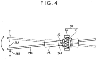
- the stylus-displacement detector 20 includes: a bracket 22 (a body) that is detachably suspended from the X-slider 48 via a bolt 21 and is supported by the X-slider 48; a measurement arm 24 that is supported by the bracket 22 swingably in the vertical direction (movably in a circular movement) around a rotary shaft 23 (a support shaft); a pair of styluses 26A and 26B provided at an end of the measurement arm 24; a displacement detector 27 that detects a circular movement amount (displacement in the Z-axis direction) of the measurement arm 24; a counterweight 29 that is adjustably positioned on the measurement arm 24; a measurement-arm attitude switching mechanism 60 that switches an attitude of the measurement arm 24 between a first attitude where the measurement arm 24 is biased in one direction (the upward direction) of the circular movement and a second attitude where the measurement arm 24 is biased in the other direction (the downward direction) of the circular movement; and a casing 28 that houses the bracket 22, the measurement arm 24, the
- the measurement arm 24 includes: a first measurement arm 24A that is supported by the bracket 22 movably in a vertical direction of the circular movement around the rotary shaft 23; and a second measurement arm 24B that is exchangeably attached to an end of the first measurement arm 24A via an attachment-detachment mechanism 25.
- the attachment-detachment mechanism 25 connects the first measurement arm 24A to the second measurement arm 24B in alignment with each other.
- the styluses 26A and 26B project from the second measurement arm 24B in circular movement directions.
- the stylus 26A projects perpendicularly upward from the second measurement arm 24B and the stylus 26B projects perpendicularly downward from the second measurement arm 24B.
- the displacement detector 27 is provided along a range of the circular movement and includes a position detector that outputs pulse signals of a number corresponding to the circular movement amount of the measurement arm 24.
- the displacement detector 27 includes a scale 27A that is provided to the measurement arm 24 and is curved in the circular movement directions of the measurement arm 24; and a detection head 27B that is attached to the bracket 22 (the body) to face the scale 27A.
- a detecting surface of the scale 27A is on the axis of the measurement arm 24 and on a plane of the circular movement of the measurement arm 24. This arrangement allows the detecting surface of the scale 27A, the measurement arm 24 and ends of the styluses 26A and 26B to be coaxially located.
- a position of the counterweight 29 is adjustable in the axial direction of the measurement arm 24 such that the weight on a side of the first measurement arm 24A and the weight on a side of the second measurement arm 24B are balanced around the rotary shaft 23.
- the counterweight 29 is fixed to the measurement arm 24 at a desired position by a setscrew.
- the measurement arm 24 may be externally threaded to provide a male thread.
- the counterweight 29 may be screwed to the male thread so as to adjust its position.
- the measurement-arm attitude switching mechanism 60 includes: a cylindrical magnet 61 in the middle of the first measurement arm 24A; and a voice coil 62 that is fixed to the bracket 22 (the body) to penetrate the magnet 61 and biases the measurement arm 24 in one direction (the upward direction) of the circular movement around the rotary shaft 23 and in the other direction (the downward direction) thereof.
- the measurement-arm attitude switching mechanism 60 is controlled by a command from a measurement attitude/measuring force control circuit 70.
- the magnet 61 of the measurement arm 24 is attracted by the voice coil 62 by an electromagnetic force generated by the voice coil 62 and a magnetic force of the magnet 61, so that an attitude of the measurement arm 24 is switched to an attitude where the end of the measurement arm 24 is biased upward or to an attitude where the end of the measurement arm 24 is biased downward.
- the measurement-arm attitude switching mechanism 60 includes the voice coil 62 biasing the measurement arm 24 in the circular movement directions around the rotary shaft 23 (the fulcrum) and also serves as a measurement force applier that applies a measurement force to the styluses 26A and 26B by biasing the measurement arm 24 in the circular movement directions.
- the measurement attitude/measuring force control circuit 70 as a speed control mechanism includes: a command signal generator 72 that is provided by CPU and the like and generates a voltage A (a command speed signal) corresponding to a predetermined speed in accordance with a balance command, a switching operation command (an upward switching operation command or a downward switching operation command) and a measurement force command which are outputted from a later-described controller 101; a digital/analog converter 73 that converts the voltage A (a digital signal) from the command signal generator 72 to an analog signal; a frequency/voltage converter 74 as a measurement-arm speed detector that outputs a voltage B (operation speed signal) corresponding to an operation speed of the measurement arm 24 based on a pulse signal (frequency) from the displacement detector 27; a subtractor 75 as a difference output unit that outputs a differential voltage C as a difference between the command speed signal (the voltage A) and the operation speed signal (the voltage B); and a constant current circuit 76 that converts the
- the voltage A (command speed signal) generated from the command signal generator 72 is set at a speed such that the styluses 26A and 26B or the object are not damaged when the styluses 26A and 26B are brought into contact with the object.
- the attachment-detachment mechanism 25 is disposed in the casing 28.
- the attachment-detachment mechanism 25 includes: a rectangular first plate 81 that is provided to the end of the first measurement arm 24A; a rectangular second plate 82 that is provided to a base end of the second measurement arm 24B; a positioning mechanism 83 that positions the second plate 82 at a predetermined position relative to the first plate 81 when placing the second plate 82 to face the first plate 81; a magnet 95 provided on the first plate 81; and a magnetic material 96 that is provided on the second plate 82 and is attracted by the magnet 95.
- the positioning mechanism 83 includes: a first seat 85 including a pair of cylindrical positioning members 84A and 84B that are arranged in parallel to the axial direction of the measurement arm 24 and are spaced from each other at a predetermined interval; a second seat 86 including a pair of cylindrical positioning members 84A and 84B that are arranged in parallel to the axial direction of the measurement arm 24 and are spaced from the first seat 85 in the axial direction of the measurement arm 24; a third seat 87 including a pair of cylindrical positioning members 84A and 84B that are perpendicular to the axial direction of the measurement arm 24 and are spaced from each other at a predetermined interval; engagement balls 88, 89 and 90 that respectively correspond to the first seat 85, the second seat 86 and the third seat 87 to be respectively engageable with and disengageable from the first seat 85, the second seat 86 and the third seat 87; at least two engagement holes 91 and 92; and at least two engagement pins 93 and 94 that are respectively engaged with the engagement holes
- the first seat 85, the second seat 86, the third seat 87 and the engagement pins 93 and 94 are arranged on the first plate 81. Specifically, the first seat 85 and the second seat 86 are arranged on both ends of the first plate 81 that are spaced in the axial direction of the measurement arm 24.
- the third seat 87 is arranged lower than and between the first seat 85 and the second seat 86.
- the engagement pins 93 and 94 are respectively arranged beneath the first seat 85 and the second seat 86.
- the magnet 95 is surrounded by the first, second and third seats 85, 86 and 87.
- the engagement balls 88, 89 and 90 and the engagement holes 91 and 92 are arranged on the second plate 82.
- the engagement balls 88, 89 and 90 are arranged to respectively correspond to the first, second and third seats 85, 86 and 87 of the first plate 81;
- the engagement holes 91 and 92 are arranged to respectively correspond to the engagement pins 93 and 94; and the magnetic material 96 is arranged to correspond to the magnet 95.
- the engagement balls 88, 89 and 90 are arranged to fit between the respective cylindrical positioning members 84A and 84B while being in contact therewith.
- the pairs of cylindrical positioning members 84A and 84B for the first, second and third seats 85, 86 and 87 and the engagement balls 88, 89 and 90 are formed of a conductive material. As shown in Fig.
- seat sensors 97, 98 and 99 are configured such that the seat sensors 97, 98 and 99 are closed when the pairs of cylindrical positioning members 84A and 84B for the first, second and third seats 85, 86 and 87 are in contact with the engageable/disengageable engagement balls 88, 89 and 90 while the seat sensors 97, 98 and 99 are opened when the pairs of cylindrical positioning members 84A and 84B are separated from the engagement balls 88, 89 and 90.
- the seat sensors 97, 98 and 99 are connected to each other in series and connected to a contact detection circuit 100.
- the contact detection circuit 100 detects opening/closing of the seat sensors 97, 98 and 99 and notifies the opening/closing by ON/OFF of a lamp, display on a display section or a sound of a buzzer or the like.
- a projecting amount of each of the engagement pins 93 and 94 is set such that the magnetic material 96 is attracted by the magnet 95 after the engagement pins 93 and 94 start to be engaged with the engagement holes 91 and 92.
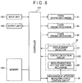
- Fig. 8 shows a control system of the surface texture measuring instrument according to the exemplary embodiment.
- the controller 101 is connected with the Y-axis driving mechanism 41, the Z-axis driving mechanism 44, the X-axis driving mechanism 45, the displacement detector 27, the contact detection circuit 100, the measurement-arm attitude switching mechanism 60, an input unit 102, an output unit 103 and a memory 104, in which the displacement detector 27, the contact detection circuit 100, the measurement-arm attitude switching mechanism 60 provides the stylus-displacement detector 20, and the measurement-arm attitude switching mechanism 60 is connected to the controller 101 via the measurement attitude/measuring force control circuit 70.
- the controller 101 is configured to serve as a drive stopper that stops driving the relative movement mechanism 40 (the Y-axis driving mechanism 41, the Z-axis driving mechanism 44 and the X-axis driving mechanism 45) when the contact detection circuit 100 detects opening of any one of the seat sensors 97, 98 and 99.
- the controller 101 is configured to also serve as a balance adjuster that adjusts balance of the measurement arm 24 by adjusting the electric current passing through the voice coil 62 of the measurement-arm attitude switching mechanism 60 after the second measurement arm 24B is exchanged.
- the controller 101 is configured to serve as the balance adjuster that adjusts the electric current passing through the voice coil 62 while monitoring the circular movement amount of the measurement arm 24 detected by the displacement detector 27 and terminates the balance adjustment when the circular movement amount reaches a predetermined value.
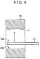
- the relative movement mechanism 40 is driven to position the styluses 26A and 26B of the measurement arm 24 in the hole H of the object W1, and then, a downward switching operation command and a measurement force command are outputted from the controller 101.
- the end of the measurement arm 24 is biased downward by the measurement attitude/measuring force control circuit 70 and the electric current according to the measurement force command is supplied to the voice coil 62 of the measurement-arm attitude switching mechanism 60.
- the measurement arm 24 is operated at the predetermined speed in a direction by the measurement-arm attitude switching mechanism 60 to bias the end of the measurement arm 24, for instance, downward and the downward stylus 26B is brought into contact with the lower surface of the hole H by the command measurement force.
- the displacement detector 27 detects the circular movement amount of the measurement arm 24. A surface texture of the lower surface of the hole H is measured based on the circular movement amount.
- the controller 101 outputs an upward switching operation command and the measurement force command.
- the measurement arm 24 is operated at the predetermined speed in a direction by the measurement-arm attitude switching mechanism 60 to bias the end of the measurement arm 24 upward and the upward stylus 26A is brought into contact with the upper surface of the hole H by the command measurement force.
- the displacement detector 27 detects the circular movement amount of the measurement arm 24. A surface texture of the upper surface of the hole H is measured based on the circular movement amount.
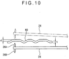
- the controller 101 commands to drive the relative movement mechanism 40 and position the styluses 26A and 26B of the measurement arm 24 at a lower surface of the object W3 and then commands the measurement-arm attitude switching mechanism 60 to switch the attitude of the measurement arm 24 to bias the end of the measurement arm 24 in an upward direction of the circular movement, thereby bringing the upward stylus 26A into contact with the lower surface of the object.
- the displacement detector 27 detects the circular movement amount of the measurement arm 24. A surface texture of the lower surface of the object W3 is measured based on the circular movement amount.
- the controller 101 commands to drive the relative movement mechanism 40 and position the styluses 26A and 26B of the measurement arm 24 toward an upper surface of the object W3 and then commands the measurement-arm attitude switching mechanism 60 to switch the attitude of the measurement arm 24 to bias the end of the measurement arm 24 in a downward direction of the circular movement, thereby bringing the downward stylus 26B into contact with the upper surface of the object W3.
- the displacement detector 27 detects the circular movement amount of the measurement arm 24. A surface texture of the upper surface of the object W3 is measured based on the circular movement amount.
- the thickness t and a distance d of the object W3 can be accurately measured based on the thus obtained surface texture of the lower and upper surfaces of the object W3.
- the surface texture of the upper and lower surfaces of the hole H, the object W3 and the like can be measured by switching the biasing direction of the measurement arm 24 by the measurement-arm attitude switching mechanism 60, specifically, switching the attitude of the measurement arm 24 between one direction (the upward direction) of the circular movement directions of the measurement arm 24 to the other direction (the downward direction).
- the measurement attitude/measuring force control circuit 70 controls the operation speed of the measurement arm 24 to be the predetermined speed.
- the displacement detector 27 outputs the pulse signals of the number corresponding to the circular movement amount of the measurement arm 24.
- the frequency/voltage converter 74 detects a voltage B corresponding to the operation speed of the measurement arm 24 based on the pulse signal from the displacement detector 27.
- a difference between the voltage B corresponding to the operation speed of the measurement arm 24 and the voltage A corresponding to the command speed signal outputted from the command signal generator 72 is obtained as the differential voltage C. Since the electric current passing through the voice coil 62 is controlled based on the differential voltage C, the switching operation speed of the measurement arm 24 can be kept according to the command speed signal outputted from the command signal generator 72.
- the operation speed of the measurement arm 24 can be kept at the predetermined speed or lower, impact can be suppressed when the styluses 26A and 26B collide with the inner surface of the hole H. Consequently, damage to the styluses 26A and 26B and the object W1 can be reduced.
- the operation speed of the measurement arm 24 can be kept at any command speed, the operation speed of the measurement arm 24 can be set at a speed suitable for a material of the object and the like.
- the measurement attitude/measuring force control circuit 70 uses the circular movement amount of the measurement arm 24, specifically, the pulse signals from the displacement detector 27 detecting the displacement of the styluses 26A and 26B, a speed detector detecting the switching operation speed of the measurement arm 24 is not required, so that the measurement attitude/measuring force control circuit 70 can be manufactured at a low cost and in a compact size.
- the displacement detector 27 of the stylus-displacement detector 20 since the displacement detector 27 of the stylus-displacement detector 20 includes the scale 27A and the detection head 27B and the detecting surface of the scale 27A is on the axis of the measurement arm 24 and on the plane of the circular movement of the measurement arm 24, errors caused by offset and the like can be reduced and a highly accurate measurement can be expected.
- the engagement pins 93 and 94 are caught in the engagement holes 91 and 92, so that the second measurement arm 24B is less likely to fall. Furthermore, even when the second measurement arm 24B is detached from the attachment-detachment mechanism 25 after external force acts on the measurement arm 24 and the styluses 26A and 26B, the second measurement arm 24B is less likely to fall since the attachment-detachment mechanism 25 is arranged in the casing 28. Accordingly, damage to the measurement arm 24 and the styluses 26A and 26B can be prevented.
- the attachment-detachment mechanism 25 is arranged in the casing 28, the attachment-detachment mechanism 25 is not likely to collide with the object, so that the attachment-detachment mechanism 25 is less likely to be damaged by collision with the object and less likely to be dirty by external environments.
- driving of the relative movement mechanism 40 is stopped by the controller 101 serving as the drive stopper, when the contact detection circuit 100 detects the opening of any one of the seat sensors 97, 98 and 99. For instance, even when the second measurement arm 24B is detached from the attachment-detachment mechanism 25, the driving of the relative movement mechanism 40 is stopped, so that the measurement can safely be performed.
- the second plate 82 with the original second measurement arm 24B is separated from the first plate 81 with the first measurement arm 24A by a force larger than the attraction force of the magnet 95, and the second plate 82 with the second measurement arm 24B having another stylus is arranged to face the first plate 81.
- the magnetic material 96 becomes attracted by the magnet 95, whereby the second plate 82 becomes attracted by the first plate 81.
- the engagement balls 88, 89 and 90 each are fit into a right position between the pair of cylindrical positioning members 84A and 84B of each of the seats 85, 86 and 87 while being guided by the pair of cylindrical positioning members 84A and 84B.
- another second measurement arm 24B can be attached by a one-touch operation in which the second plate 82 is placed to face the first plate 81 such that the first plate 81 and the second plate 82 substantially coincide with each other.
- the measurement can be performed by exchange with a second measurement arm 24B having the most suitable stylus for a profile of the measurement portion of the object.
- the engagement pins 93 and 94 on the first plate 81 are brought into engagement with the engagement holes 91 and 92 formed on the second plate 82. Since the projecting amount of each of the engagement pins 93 and 94 is set such that the magnetic material 96 is attracted by the magnet 95 after the engagement pins 93 and 94 start to be engaged with the engagement holes 91 and 92, even without visual check, it can be recognized by feeling through the attraction force of the magnet 95 that the second plate 82 is connected to the first plate 81 at a right position.
- the contact detection circuit 100 can detect the opening/closing of the seat sensors 97, 98 and 99, it can be checked whether the second measurement arm 24B has been suitably exchanged.
- the attachment-detachment mechanism 25 is provided in the casing 28, in other words, the attachment-detachment mechanism 25 is closer to the rotary shaft 23 (fulcrum) of the measurement arm 24 as compared with an attachment-detachment mechanism 25 provided outside the casing 28. Accordingly, moment applied on the fulcrum can be reduced in the attachment/detachment of the second measurement arm 24B, so that load applied on a bearing of the fulcrum can be reduced and damage prevention effect to the bearing can be expected.
- the third seat 87 restricts an axial displacement of the measurement arm 24 and the first and second seats 85 and 86 restrict a rotary displacement of the measurement arm 24 around the engagement ball 88 engaged with the first seat 85. Accordingly, the first and second plates 81 and 82 can accurately be positioned in a predetermined relation. Moreover, under such a condition, since the first seat 85 is spaced from the second seat 86 in the axial direction of the measurement arm 24, the measurement arm 24 can be held by a relatively compact arrangement and a small force. A longer distance between the first seat 85 and the second seat 86 is preferable. As in this exemplary embodiment, the first seat 85 and the second seat 86 are preferably arranged at both ends of the first plate 81 spaced from each other in the axial direction of the measurement art 24.
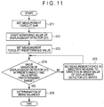
- the controller 101 outputs a setting command to set a measurement force at 0 in step (hereinafter referred to as "ST") 1 and starts monitoring a value of the displacement detector 27 in ST2.
- the controller 101 outputs a setting command to set the measurement force at a predetermined value.
- the controller 101 checks whether a value variation of the displacement detector 27 in a predetermined period of time falls within a predetermined range.
- the operation proceeds to ST5.
- the controller 101 outputs a setting command to set the measurement force in a direction reverse to a direction in which the values of the displacement detector 27 vary.
- the processing of ST5 is repeated until the value variation of the displacement detector 27 in the predetermined period of time falls within the predetermined range.
- the controller 101 determines in ST6 that the measurement arm 24 becomes in balance and terminates the processing.
- the measurement force in the measurement is determined by defining a measurement force in good balance as 0 and adding a measurement force to be applied during the measurement.
- the controller 101 serving as the balance adjuster can automatically adjust the balance of the measurement arm 24 by adjusting the electric current passing through the voice coil 62 even when a weight of the exchanged second measurement arm 24B after the exchange is different from a weight of the previous second measurement arm 24B. Consequently, a measurement error caused by the exchange with the second measurement arm 24B can be decreased and improvement in usability and an operational efficiency can be expected.
- the balance adjustment of the measurement arm 24 can accurately be performed since the balance adjuster adjusts the electric current passing through the voice coil 62 while monitoring the circular movement amount of the measurement arm 24 detected by the displacement detector 27 and terminates the balance adjustment when the circular movement amount reaches the predetermined value.
- the invention is not limited to the above-described exemplary embodiment but may include modification(s) and improvement(s) made within a scope where an object of the invention can be attained.
- the first, second and third seats 85, 86 and 87 for the attachment-detachment mechanism 25 are provided on the first plate 81, and the engagement balls 88, 89 and 90 respectively engageable/disengageable to the first, second and third seats 85, 86 and 87 are provided on the second plate 82.
- the first, second and third seats 85, 86 and 87 may be provided on the second plate 82 and the engagement balls 88, 89 and 90 may be provided on the first plate 81.
- the magnet 95 is provided on first plate 81 and the magnetic material 96 is provided on the second plate 82.
- the magnet 95 may be provided on the second plate 82 and the magnetic material 96 may be provided on the first plate 81.
- the engagement pins 93 and 94 are provided on first plate 81 and the engagement halls 91 and 92 are provided on the second plate 82. However, the engagement pins 93 and 94 may be provided on the second plate 82 and the engagement halls 91 and 92 may be provided on the first plate 81.
- the measurement-arm attitude switching mechanism 60 includes the voice coil 62 that biases the measurement arm 24 in the upward and downward directions of the circular movement around the rotary shaft 23.
- the arrangement of the measurement-arm attitude switching mechanism 60 is not limited thereto.
- the measurement-arm attitude switching mechanism 60 may include a linear motor mechanism.
- the circular movement direction is the vertical direction in the above exemplary embodiment, but the circular movement direction may be a horizontal direction.
- the measurement arm 24 may swing in a diagonal direction other than the vertical and horizontal directions.
- the second measurement arm 24B having the pair of the styluses 26A and 26B at the end of the measurement arm 24 is described.
- the second measurement arm 24B may not have a pair of styluses. Any arrangement of the second measurement arm 24B is possible as long as the measurement arm is exchangeable for a measurement arm having a suitable stylus for a measurement portion.
- the method of adjusting the balance of the measurement arm 24 is described according to the procedure shown in the flow chart of Fig. 11 .
- the balance of the measurement arm 24 may be adjusted according to the procedure shown in the flow chart of Fig. 12 or Fig. 13 .
- the controller 101 outputs a setting command to set a maximum downward measurement force in ST11 and starts monitoring a value of the displacement detector 27 in ST12.
- the controller 101 checks whether the value of the displacement detector 27 is equal to or less than a predetermined value, in other words, whether a counter value is beyond the maximum value.
- the operation proceeds to ST14.
- the controller 101 commands to set the measurement force at a mean value of the maximum value and the minimum value or at a mean value of the past two measurement forces in a direction reverse to the direction in which the counter value is beyond the maximum value.
- the processing of ST14 is repeated until the value of the displacement detector 27 becomes equal to or less than the predetermined value.
- the operation proceeds to ST15.
- the controller 101 checks whether the value variation of the displacement detector 27 in a predetermined period of time falls within the predetermined range.
- the operation proceeds to ST16.
- the controller 101 commands to set the measurement force at the mean value of the maximum value and the minimum value or at the mean value of the past two measurement forces in a direction reverse to the direction in which the value of the displacement detector 27 varies, and the processing returns to ST13.
- the controller 101 determines in ST17 that the measurement arm 24 becomes in balance and terminates the processing.
- the controller 101 outputs a setting command to set a maximum downward measurement force in ST21 and the measurement arm 24 is held at the middle position from the position of the maximum downward measurement force in ST22.
- the controller 101 outputs the setting command to set the measurement force at 0.
- the measurement arm 24 is allowed to move downward.
- the controller 101 starts monitoring the value of the displacement detector 27.
- the controller 101 checks whether the value of the displacement detector 27 is equal to or less than the predetermined value, in other words, whether a counter value is beyond the maximum value or not.
- the operation proceeds to ST27.
- the controller 101 commands to set the measurement force of a predetermined value in a direction reverse to the direction in which the counter value is beyond the maximum value. The processing of ST27 is repeated until the value of the displacement detector 27 becomes equal to or less than the predetermined value in ST26.
- the operation proceeds to ST28.
- the controller 101 checks whether a value variation of the displacement detector 27 in the predetermined period of time falls within the predetermined range.
- the operation proceeds to ST29.
- the controller 101 commands to set the measurement force at a half of the mean value of the past two measurement forces or a measurement force of the previously set measurement force in a direction reverse to the direction in which the value of the displacement detector 27 varies, and the processing returns to ST26.
- the controller 101 determines in ST30 that the measurement arm 24 becomes in balance and terminates the processing.
- the measurement attitude/measuring force control circuit 70 is arranged as shown in Fig. 5 .
- the arrangement of the measurement attitude/measuring force control circuit 70 is not limited thereto.
- the measurement attitude/measuring force control circuit 70 may be a circuit as shown in Fig. 14 .
- the measurement attitude/measuring force control circuit 70 shown in Fig. 14 includes a calculation controller 77 that calculates the switching operation speed of the measurement arm 24 based on the pulse signals (positional information) from the displacement detector 27 and generates a voltage (a control signal) such that the calculated switching operation speed conform with the predetermined command speed; a digital/analog converter 73 that converts the voltage (the control signal) from the calculation controller 77 into an analog signal; and a constant current circuit 76 that generates electric current passing through the voice coil 62 based on the output from the digital/analog converter 73.
- the pulse signals (positional information) of the number corresponding to the circular movement amount of the measurement arm 24 is outputted.
- the calculation controller 77 calculates an operation speed of a currently used measurement arm 24 based on the elapsed time and the pulse signal (positional information) from the displacement detector 27, compares the calculated operation speed with the command speed corresponding to the operation command given by the controller 101, and generates the voltage (the control signal) such that the operation speed conforms with the command speed.
- the constant current circuit 76 since the constant current circuit 76 generates the electric current to pass through the voice coil 62 based on the control signal generated from the calculation controller 77, the operation speed of the measurement arm 24 can be kept at the command speed. Accordingly, the same advantages as those in the above exemplary embodiment can be expected.
- the relative movement mechanism 40 enables the stage 10 to move in the Y-axis direction and the stylus-displacement detector 20 to move in the X-axis direction and the Z-axis direction, the invention is not limited thereto. In other words, as long as the stage 10 and the stylus-displacement detector 20 are movable in the three dimensional directions, any one or both of the stage 10 and the stylus-displacement detector 20 may be movable.
Landscapes
- Physics & Mathematics (AREA)
- General Physics & Mathematics (AREA)
- A Measuring Device Byusing Mechanical Method (AREA)
- Length Measuring Devices With Unspecified Measuring Means (AREA)
Claims (5)
- Ein Instrument zur Messung von Oberflächentexturen, das Folgendes umfasst:einen Messarm (24), der von einem Körper (22) in einer Kreisbewegung um eine Rotationswelle (23) drehbar getragen wird;einen Taststift (26A, 26B), der an einem Ende des Messarms (24) bereitgestellt wird;ein Verschiebungsdetektor bzw. Wegaufnehmer (27), der einen Kreisbewegungsbetrag des Messarms (24) erfasst;einen Detektor (20), der ein Gehäuse (28) aufweist, das den Körper (22) aufnimmt;einen Tisch (10), auf dem ein zu messender Gegenstand (W1, W3) montiert wird; undeinen Relativbewegungs-Mechanismus (40), der den Detektor (20) und den Tisch (10) relativ zueinander bewegt, wobei das Messinstrument für Oberflächentexturen konfiguriert ist, um den Kreisbewegungsbetrag des Messarms (24) durch den Wegaufnehmer (27) zu erfassen, während der Detektor (20) und der Tisch (10) durch den Relativbewegungs-Mechanismus (40) relativ zueinander bewegt werden, wobei der Taststift (26A, 26B) mit einer Oberfläche des Gegenstandes (W1, W3) in Kontakt steht, und um eine Oberflächentextur des Gegenstandes auf der Grundlage des Kreisbewegungsbetrags zu messen, wobeider Messarm (24) Folgendes umfasst: einen ersten Messarm (24A), der durch den Körper (22) schwenkbar um die Rotationswelle (23) im Gehäuse (28) getragen wird; und einen zweiten Messarm (24B), der mit dem Taststift (26A, 26B) an einem seiner Enden versehen ist und lösbar für ein Ende des ersten Messarms (24A) über einen Befestigungs- und Abnahme-Mechanismus (25) bereitgestellt wird, wobei der Befestigungs- und Abnahme-Mechanismus (25) im Gehäuse (28) angeordnet ist,wobei der Wegaufnehmer (27) Folgendes umfasst: eine Skala (27A), die für den Messarm (24A, 24B) bereitgestellt wird; und einen Detektionskopf (27B), der für den Körper (22) bereitgestellt wird, um der Skala (27A) gegenüberzustehen,wobei eine Erfassungsfläche der Skala (27A) in einer Achse des Messarmes (24A, 24B) und in einer Ebene der Kreisbewegung des Messarms (24A, 24B) liegt,wobei der Befestigungs- und Abnahme-Mechanismus (25) Folgendes umfasst:eine erste Platte (81), die am Ende des ersten Messarms (24A) befestigt ist; eine zweite Platte (82), die an einem Basisende des zweiten Messarms (24B) befestigt ist;ein Positionierungs-Mechanismus (83), der die zweite Platte (82) an einer vorbestimmten Position relativ zur ersten Platte (81) positioniert, wenn die zweite Platte (82) so gestellt wird, dass sie der ersten Platte (81) gegenübersteht; ein Magnet (95), der an einer der ersten (81) oder zweiten Platte (82) bereitgestellt wird;und ein magnetisches Material (96), das an der anderen der ersten (81) oder zweiten Platte (82) bereitgestellt wird und vom Magneten (95) angezogen wird,wobei der Positionierungs-Mechanismus (83) Folgendes umfasst: einen ersten Sitz (85), der ein Paar zylindrische Positionierungselemente (84A, 84B) umfasst, die parallel zu einer axialen Richtung des Messarmes (24) angeordnet sind und voneinander in einem vorgegebenen Intervall beabstandet sind; einen zweiten Sitz (86), der ein Paar zylindrische Positionierungselemente (84A, 84B) umfasst, die parallel zur axialen Richtung des Messarmes (24) angeordnet sind und vom ersten Sitz (85) in axialer Richtung des Messarmes (24) beabstandet sind; einen dritten Sitz (87), der ein Paar zylindrische Positionierungselemente (84A, 84B) umfasst, die zur axialen Richtung des Messarmes (24) senkrecht stehen und voneinander in einem vorgegebenen Intervall beabstandet sind; und Eingriffskugeln (engagement balls) (88, 89, 90), die jeweils dem ersten Sitz (85), dem zweiten Sitz (86) und dem dritten Sitz (87) entsprechen, um mit dem ersten Sitz (85), dem zweiten Sitz (86) und dem dritten Sitz (87) in Eingriff zu kommen oder sich von diesen zu lösen, und wobeider erste Sitz, der zweite Sitz und der dritte Sitz auf einer der ersten (81) oder zweiten Platte (82) bereitgestellt werden und die Eingriffskugeln (88, 89, 90) auf der anderen der ersten (81) oder zweiten Platte (82) bereitgestellt werden.
- Das Instrument zur Messung von Oberflächentexturen nach Anspruch 1, wobei
der Positionierungs-Mechanismus (83) Folgendes umfasst: mindestens zwei Eingriffslöcher (91, 92), die auf einer der ersten (81) oder zweiten Platte (82) gebildet werden; und mindestens zwei Eingriffszapfen (93, 94), die auf der anderen der ersten (81) oder zweiten Platte (82) bereitgestellt werden, die mit den Eingriffslöchern (91, 92) in Eingriff zu bringen sind. - Das Instrument zur Messung von Oberflächentexturen nach Anspruch 2, wobei
ein Vorsprungsbetrag eines jeden der Eingriffszapfen (93, 94) derart gesetzt wird, dass das magnetische Material (96) vom Magneten (95) angezogen wird, nachdem die Eingriffszapfen (93, 94) anfangen, mit Eingriffslöchern (91, 92) in Eingriff zu kommen. - Das Instrument zur Messung von Oberflächentexturen nach irgendeinem der vorhergehenden Ansprüche von 1 bis 3, wobei
die Paare von zylindrischen Positionierungselementen (84A, 84B) für die ersten, zweiten und dritten Sitze (85, 86, 87) und die Eingriffskugeln (88, 89, 90) aus einem leitenden Material gebildet werden und Sitzsensoren (97, 98, 99) bereitstellen, die geschlossen sind, wenn die Paare von zylindrischen Positionierungselementen (84A, 84B) jeweils mit den Eingriffskugeln (88, 89, 90) in Kontakt sind, damit in und außer Eingriff bringbar, und die offen sind, wenn die Paare von zylindrischen Positionierungselementen (84A, 84B) jeweils von den Eingriffskugeln (88, 89, 90) getrennt sind, und wobei
eine Berührungs-Feststellungs-Schaltung (100) bereitgestellt wird, die ein Öffnen und Schließen der Sitzsensoren (97, 98, 99) erfasst. - Das Instrument zur Messung von Oberflächentexturen nach Anspruch 4, das des Weiteren Folgendes umfasst:ein Antriebs-Stopper, der den Relativbewegungs-Mechanismus (40) stoppt, wenn die Berührungs-Feststellungs-Schaltung (100) ein Öffnen von irgendeinem der Sitzsensoren (97, 98, 99) erfasst.
Applications Claiming Priority (2)
| Application Number | Priority Date | Filing Date | Title |
|---|---|---|---|
| JP2011092980A JP5735336B2 (ja) | 2011-04-19 | 2011-04-19 | 表面性状測定機 |
| JP2011092981A JP5735337B2 (ja) | 2011-04-19 | 2011-04-19 | 表面性状測定機 |
Publications (3)
| Publication Number | Publication Date |
|---|---|
| EP2515069A2 EP2515069A2 (de) | 2012-10-24 |
| EP2515069A3 EP2515069A3 (de) | 2012-11-07 |
| EP2515069B1 true EP2515069B1 (de) | 2016-03-16 |
Family
ID=46049130
Family Applications (1)
| Application Number | Title | Priority Date | Filing Date |
|---|---|---|---|
| EP12002238.9A Active EP2515069B1 (de) | 2011-04-19 | 2012-03-28 | Messinstrument für Oberflächenstrukturen |
Country Status (3)
| Country | Link |
|---|---|
| US (1) | US8701301B2 (de) |
| EP (1) | EP2515069B1 (de) |
| CN (1) | CN102749058B (de) |
Cited By (2)
| Publication number | Priority date | Publication date | Assignee | Title |
|---|---|---|---|---|
| CN107167058A (zh) * | 2017-07-17 | 2017-09-15 | 安徽江淮汽车集团股份有限公司 | 制件检具 |
| DE202022107166U1 (de) | 2022-04-14 | 2023-01-19 | Carl Mahr Holding Gmbh | Trägereinrichtung für ein Objekt und Halterung für die Trägereinrichtung |
Families Citing this family (36)
| Publication number | Priority date | Publication date | Assignee | Title |
|---|---|---|---|---|
| GB201007186D0 (en) * | 2010-04-30 | 2010-06-09 | Renishaw Plc | Changeable task module counterweight |
| US8701301B2 (en) * | 2011-04-19 | 2014-04-22 | Mitutoyo Corporation | Surface texture measuring instrument |
| JP5823266B2 (ja) | 2011-11-29 | 2015-11-25 | 株式会社ミツトヨ | 表面性状測定機 |
| JP5875900B2 (ja) | 2012-03-08 | 2016-03-02 | 株式会社ミツトヨ | 表面性状測定機、その制御装置およびその調整方法 |
| JP6030320B2 (ja) | 2012-03-19 | 2016-11-24 | 株式会社ミツトヨ | 表面性状測定機 |
| JP6104557B2 (ja) | 2012-10-18 | 2017-03-29 | 株式会社ミツトヨ | 表面粗さ測定ユニット、三次元測定装置 |
| JP6047045B2 (ja) * | 2013-03-25 | 2016-12-21 | 株式会社ミツトヨ | 輪郭測定機 |
| JP6133678B2 (ja) * | 2013-05-01 | 2017-05-24 | 株式会社ミツトヨ | 表面性状測定装置およびその制御方法 |
| CN103278120B (zh) * | 2013-06-18 | 2015-09-23 | 孟庆周 | 一种接触式测量头结构 |
| CN103278119B (zh) * | 2013-06-18 | 2015-09-02 | 孟庆周 | 一种测针自动化调整的接触式测量头结构 |
| JP6282517B2 (ja) * | 2014-04-09 | 2018-02-21 | 株式会社ミツトヨ | 形状測定機 |
| JP6518421B2 (ja) | 2014-09-24 | 2019-05-22 | 株式会社ミツトヨ | 真円度測定機およびその制御方法 |
| JP5846462B1 (ja) * | 2014-10-28 | 2016-01-20 | 株式会社東京精密 | 形状測定装置 |
| DE102015203369B4 (de) | 2015-02-25 | 2020-02-20 | Carl Zeiss Industrielle Messtechnik Gmbh | Verfahren zum Bestimmen der Messbedingungen eines Rauheitssensors, Verfahren zum Vermessen der Rauheit einer Werkstückoberfläche, Computerprogrammprodukt sowie Messgerät eingerichtet zur Durchführung der Verfahren |
| JP6039718B2 (ja) | 2015-03-05 | 2016-12-07 | 株式会社ミツトヨ | 測定プローブ |
| JP6049785B2 (ja) | 2015-03-05 | 2016-12-21 | 株式会社ミツトヨ | 測定プローブ |
| JP6049786B2 (ja) | 2015-03-05 | 2016-12-21 | 株式会社ミツトヨ | 測定プローブ |
| JP6611168B2 (ja) * | 2015-04-07 | 2019-11-27 | 株式会社ミツトヨ | プローブ測定力調整装置 |
| DE102015209193A1 (de) | 2015-05-20 | 2016-11-24 | Carl Zeiss Industrielle Messtechnik Gmbh | Verfahren zur Erfassung dynamischer Schwingungen eines Rauheitssensors, Verfahren zur Vermessung der Rauheit einer Werkstückoberfläche, Computerprogrammprodukt sowie Messgerät eingerichtet zur Durchführung der Verfahren. |
| DE102017105814B3 (de) | 2017-03-17 | 2018-05-30 | Carl Zeiss Industrielle Messtechnik Gmbh | System zum Messen der Rauheit einer Oberfläche eines Werkstücks |
| DE102017106741B4 (de) * | 2017-03-29 | 2019-11-14 | Jenoptik Industrial Metrology Germany Gmbh | Oberflächenmessgerät |
| JP6777589B2 (ja) * | 2017-05-24 | 2020-10-28 | 株式会社ミツトヨ | 表面性状測定装置 |
| DE102017113699B3 (de) | 2017-06-21 | 2018-06-28 | Carl Mahr Holding Gmbh | Messsystem mit einer Kugelführungseinheit für ein Messgerät |
| DE102017113695B3 (de) | 2017-06-21 | 2018-12-27 | Carl Mahr Holding Gmbh | Wippenloses Messsystem für ein Messgerät |
| KR101888466B1 (ko) * | 2018-02-12 | 2018-08-16 | 황재은 | 형상측정기 |
| DE102018103420A1 (de) * | 2018-02-15 | 2019-08-22 | Jenoptik Industrial Metrology Germany Gmbh | Messgerät zur Oberflächen- oder Konturmessung |
| JP7121895B2 (ja) * | 2018-03-29 | 2022-08-19 | 株式会社東京精密 | 形状測定機 |
| JP7073211B2 (ja) | 2018-06-30 | 2022-05-23 | 株式会社ミツトヨ | 表面性状測定装置の制御方法 |
| JP7213059B2 (ja) * | 2018-10-24 | 2023-01-26 | 株式会社ミツトヨ | 表面性状測定装置およびその制御方法 |
| JP7261560B2 (ja) * | 2018-10-31 | 2023-04-20 | 株式会社ミツトヨ | 表面性状測定方法および表面性状測定装置 |
| JP6788207B2 (ja) | 2019-04-16 | 2020-11-25 | 株式会社東京精密 | 変位検出器、表面性状測定機、及び真円度測定機 |
| CN112710271A (zh) * | 2020-12-29 | 2021-04-27 | 苏州泰科贝尔直驱电机有限公司 | 一种高精度三轴联动旋转平台 |
| CN114963969A (zh) * | 2022-05-13 | 2022-08-30 | 扬州澳洋顺昌金属材料有限公司 | 一种锌锅内壁腐蚀程度测量装置 |
| JP2024142967A (ja) | 2023-03-30 | 2024-10-11 | 株式会社ミツトヨ | 測定装置 |
| CN117490557A (zh) * | 2023-10-09 | 2024-02-02 | 深圳市中图仪器股份有限公司 | 测量力调节装置 |
| DE102024123822A1 (de) | 2024-08-21 | 2026-02-26 | Carl Mahr Holding Gmbh | Haltevorrichtung, Messarm und Messarmhalterung für ein Messsystem |
Family Cites Families (17)
| Publication number | Priority date | Publication date | Assignee | Title |
|---|---|---|---|---|
| JPS5883201A (ja) | 1981-11-13 | 1983-05-19 | Tokyo Seimitsu Co Ltd | 形状測定器 |
| GB2256476B (en) | 1991-05-30 | 1995-09-27 | Rank Taylor Hobson Ltd | Positional measurement |
| JPH0526601A (ja) * | 1991-06-18 | 1993-02-02 | Nikken Kosakusho:Kk | 接触検出装置 |
| DE19617022C1 (de) | 1996-04-27 | 1997-12-11 | Mahr Gmbh | Konturenmeßgerät |
| JP3273026B2 (ja) | 1998-09-02 | 2002-04-08 | 株式会社ミツトヨ | 表面追従型測定機 |
| JP3992853B2 (ja) | 1998-09-30 | 2007-10-17 | 株式会社ミツトヨ | 表面追従型測定機 |
| DE10025461A1 (de) | 2000-05-23 | 2001-12-06 | Mahr Gmbh | Messeinrichtung nach dem Interferenzprinzip |
| JP2002340503A (ja) * | 2001-05-16 | 2002-11-27 | Mitsutoyo Corp | 表面性状測定機における被測定物の相対姿勢調整方法 |
| JP4062008B2 (ja) | 2002-08-07 | 2008-03-19 | 株式会社東京精密 | デジタル測定ヘッド |
| JP3967274B2 (ja) * | 2003-02-27 | 2007-08-29 | 株式会社ミツトヨ | 測定装置 |
| JP2005055282A (ja) | 2003-08-04 | 2005-03-03 | Tokyo Seimitsu Co Ltd | 測定方法及び測定装置 |
| JP4570437B2 (ja) * | 2004-10-20 | 2010-10-27 | 株式会社東京精密 | 表面粗さ/輪郭形状測定装置 |
| JP4323412B2 (ja) * | 2004-11-02 | 2009-09-02 | 株式会社ミツトヨ | 表面性状測定用探針およびこれを用いた顕微鏡 |
| JP4423168B2 (ja) * | 2004-11-02 | 2010-03-03 | 株式会社ミツトヨ | 表面性状測定装置 |
| DE102007018444C5 (de) | 2007-04-19 | 2011-02-17 | Carl Mahr Holding Gmbh | Tastschnitt-Messeinrichtung mit Tastermagazin zur Oberflächen- und Konturmessung |
| JP5336279B2 (ja) * | 2009-07-08 | 2013-11-06 | 株式会社ミツトヨ | 表面性状測定装置および真円度測定装置 |
| US8701301B2 (en) * | 2011-04-19 | 2014-04-22 | Mitutoyo Corporation | Surface texture measuring instrument |
-
2012
- 2012-03-26 US US13/429,679 patent/US8701301B2/en active Active
- 2012-03-28 EP EP12002238.9A patent/EP2515069B1/de active Active
- 2012-04-19 CN CN201210117021.2A patent/CN102749058B/zh active Active
Cited By (4)
| Publication number | Priority date | Publication date | Assignee | Title |
|---|---|---|---|---|
| CN107167058A (zh) * | 2017-07-17 | 2017-09-15 | 安徽江淮汽车集团股份有限公司 | 制件检具 |
| DE202022107166U1 (de) | 2022-04-14 | 2023-01-19 | Carl Mahr Holding Gmbh | Trägereinrichtung für ein Objekt und Halterung für die Trägereinrichtung |
| DE102022109267A1 (de) | 2022-04-14 | 2023-10-19 | Carl Mahr Holding Gmbh | Tasteinheit und Halterung für eine Tasteinheit |
| DE102022109267B4 (de) * | 2022-04-14 | 2025-04-10 | Carl Mahr Holding Gmbh | Tasteinheit und Halterung für eine Tasteinheit sowie Anordnung |
Also Published As
| Publication number | Publication date |
|---|---|
| US20120266475A1 (en) | 2012-10-25 |
| CN102749058A (zh) | 2012-10-24 |
| EP2515069A2 (de) | 2012-10-24 |
| CN102749058B (zh) | 2016-04-20 |
| EP2515069A3 (de) | 2012-11-07 |
| US8701301B2 (en) | 2014-04-22 |
Similar Documents
| Publication | Publication Date | Title |
|---|---|---|
| EP2515069B1 (de) | Messinstrument für Oberflächenstrukturen | |
| US8915124B2 (en) | Surface texture measuring apparatus | |
| US20090235397A1 (en) | Contact type measuring instrument | |
| US9395181B2 (en) | Thread profile measuring method | |
| JP5735337B2 (ja) | 表面性状測定機 | |
| JPH0557522B2 (de) | ||
| JP5735336B2 (ja) | 表面性状測定機 | |
| JP7614523B2 (ja) | 形状測定装置 | |
| JP7637329B2 (ja) | 形状測定装置 | |
| US11709045B1 (en) | Surface texture probe and measurement apparatus with a vibrational membrane | |
| JP5986880B2 (ja) | 測定機及びその測定力調整方法 | |
| CN113328583B (zh) | 一种伺服阀电磁零位自动精准量化调控装置及方法 | |
| CN1077681C (zh) | 微小型轴承滚道粗糙度测试仪 | |
| CN115112020A (zh) | 反射式光栅尺检测装置 | |
| JP4909562B2 (ja) | 表面性状測定装置 | |
| JP4669639B2 (ja) | 移動装置 | |
| CN222653094U (zh) | 一种用于检测环形磁体元件表磁的设备 | |
| CN114778273B (zh) | 具有检测调平移动横梁的万能试验机及检测调平方法 | |
| CN118189886A (zh) | 一种用于检测水准仪精确度的装置以及检测方法 | |
| CN115902311A (zh) | 一种基于工频磁场试验的智能夹持装置及夹持方法 | |
| JPS622253B2 (de) | ||
| CN120395554A (zh) | 基于瞬时电流感知的磁流变加工调控装置及其加工方法 | |
| JPS61219823A (ja) | 表面粗さ計測プロ−ブを有する計測装置 | |
| JPH08278209A (ja) | 微小力測定装置および微小力測定方法 | |
| JPS58160808A (ja) | 三次元自由曲面測定プローブ装置及び該装置による測定方法並びに該装置を用いた機械加工方法 |
Legal Events
| Date | Code | Title | Description |
|---|---|---|---|
| PUAL | Search report despatched |
Free format text: ORIGINAL CODE: 0009013 |
|
| PUAI | Public reference made under article 153(3) epc to a published international application that has entered the european phase |
Free format text: ORIGINAL CODE: 0009012 |
|
| AK | Designated contracting states |
Kind code of ref document: A2 Designated state(s): AL AT BE BG CH CY CZ DE DK EE ES FI FR GB GR HR HU IE IS IT LI LT LU LV MC MK MT NL NO PL PT RO RS SE SI SK SM TR |
|
| AX | Request for extension of the european patent |
Extension state: BA ME |
|
| AK | Designated contracting states |
Kind code of ref document: A3 Designated state(s): AL AT BE BG CH CY CZ DE DK EE ES FI FR GB GR HR HU IE IS IT LI LT LU LV MC MK MT NL NO PL PT RO RS SE SI SK SM TR |
|
| AX | Request for extension of the european patent |
Extension state: BA ME |
|
| RIC1 | Information provided on ipc code assigned before grant |
Ipc: G01B 5/28 20060101AFI20120928BHEP Ipc: G01B 5/00 20060101ALI20120928BHEP Ipc: G01B 3/00 20060101ALI20120928BHEP |
|
| 17P | Request for examination filed |
Effective date: 20130506 |
|
| GRAP | Despatch of communication of intention to grant a patent |
Free format text: ORIGINAL CODE: EPIDOSNIGR1 |
|
| INTG | Intention to grant announced |
Effective date: 20151021 |
|
| GRAS | Grant fee paid |
Free format text: ORIGINAL CODE: EPIDOSNIGR3 |
|
| GRAA | (expected) grant |
Free format text: ORIGINAL CODE: 0009210 |
|
| AK | Designated contracting states |
Kind code of ref document: B1 Designated state(s): AL AT BE BG CH CY CZ DE DK EE ES FI FR GB GR HR HU IE IS IT LI LT LU LV MC MK MT NL NO PL PT RO RS SE SI SK SM TR |
|
| REG | Reference to a national code |
Ref country code: GB Ref legal event code: FG4D |
|
| REG | Reference to a national code |
Ref country code: FR Ref legal event code: PLFP Year of fee payment: 5 |
|
| REG | Reference to a national code |
Ref country code: CH Ref legal event code: EP |
|
| REG | Reference to a national code |
Ref country code: IE Ref legal event code: FG4D |
|
| REG | Reference to a national code |
Ref country code: AT Ref legal event code: REF Ref document number: 781611 Country of ref document: AT Kind code of ref document: T Effective date: 20160415 |
|
| REG | Reference to a national code |
Ref country code: DE Ref legal event code: R096 Ref document number: 602012015560 Country of ref document: DE |
|
| REG | Reference to a national code |
Ref country code: NL Ref legal event code: MP Effective date: 20160316 |
|
| REG | Reference to a national code |
Ref country code: LT Ref legal event code: MG4D |
|
| PG25 | Lapsed in a contracting state [announced via postgrant information from national office to epo] |
Ref country code: NO Free format text: LAPSE BECAUSE OF FAILURE TO SUBMIT A TRANSLATION OF THE DESCRIPTION OR TO PAY THE FEE WITHIN THE PRESCRIBED TIME-LIMIT Effective date: 20160616 Ref country code: FI Free format text: LAPSE BECAUSE OF FAILURE TO SUBMIT A TRANSLATION OF THE DESCRIPTION OR TO PAY THE FEE WITHIN THE PRESCRIBED TIME-LIMIT Effective date: 20160316 Ref country code: GR Free format text: LAPSE BECAUSE OF FAILURE TO SUBMIT A TRANSLATION OF THE DESCRIPTION OR TO PAY THE FEE WITHIN THE PRESCRIBED TIME-LIMIT Effective date: 20160617 Ref country code: HR Free format text: LAPSE BECAUSE OF FAILURE TO SUBMIT A TRANSLATION OF THE DESCRIPTION OR TO PAY THE FEE WITHIN THE PRESCRIBED TIME-LIMIT Effective date: 20160316 |
|
| REG | Reference to a national code |
Ref country code: AT Ref legal event code: MK05 Ref document number: 781611 Country of ref document: AT Kind code of ref document: T Effective date: 20160316 |
|
| PG25 | Lapsed in a contracting state [announced via postgrant information from national office to epo] |
Ref country code: RS Free format text: LAPSE BECAUSE OF FAILURE TO SUBMIT A TRANSLATION OF THE DESCRIPTION OR TO PAY THE FEE WITHIN THE PRESCRIBED TIME-LIMIT Effective date: 20160316 Ref country code: NL Free format text: LAPSE BECAUSE OF FAILURE TO SUBMIT A TRANSLATION OF THE DESCRIPTION OR TO PAY THE FEE WITHIN THE PRESCRIBED TIME-LIMIT Effective date: 20160316 Ref country code: SE Free format text: LAPSE BECAUSE OF FAILURE TO SUBMIT A TRANSLATION OF THE DESCRIPTION OR TO PAY THE FEE WITHIN THE PRESCRIBED TIME-LIMIT Effective date: 20160316 Ref country code: LV Free format text: LAPSE BECAUSE OF FAILURE TO SUBMIT A TRANSLATION OF THE DESCRIPTION OR TO PAY THE FEE WITHIN THE PRESCRIBED TIME-LIMIT Effective date: 20160316 Ref country code: BE Free format text: LAPSE BECAUSE OF NON-PAYMENT OF DUE FEES Effective date: 20160331 Ref country code: LT Free format text: LAPSE BECAUSE OF FAILURE TO SUBMIT A TRANSLATION OF THE DESCRIPTION OR TO PAY THE FEE WITHIN THE PRESCRIBED TIME-LIMIT Effective date: 20160316 |
|
| PG25 | Lapsed in a contracting state [announced via postgrant information from national office to epo] |
Ref country code: IS Free format text: LAPSE BECAUSE OF FAILURE TO SUBMIT A TRANSLATION OF THE DESCRIPTION OR TO PAY THE FEE WITHIN THE PRESCRIBED TIME-LIMIT Effective date: 20160716 Ref country code: EE Free format text: LAPSE BECAUSE OF FAILURE TO SUBMIT A TRANSLATION OF THE DESCRIPTION OR TO PAY THE FEE WITHIN THE PRESCRIBED TIME-LIMIT Effective date: 20160316 Ref country code: PL Free format text: LAPSE BECAUSE OF FAILURE TO SUBMIT A TRANSLATION OF THE DESCRIPTION OR TO PAY THE FEE WITHIN THE PRESCRIBED TIME-LIMIT Effective date: 20160316 |
|
| REG | Reference to a national code |
Ref country code: CH Ref legal event code: PL |
|
| PG25 | Lapsed in a contracting state [announced via postgrant information from national office to epo] |
Ref country code: SK Free format text: LAPSE BECAUSE OF FAILURE TO SUBMIT A TRANSLATION OF THE DESCRIPTION OR TO PAY THE FEE WITHIN THE PRESCRIBED TIME-LIMIT Effective date: 20160316 Ref country code: RO Free format text: LAPSE BECAUSE OF FAILURE TO SUBMIT A TRANSLATION OF THE DESCRIPTION OR TO PAY THE FEE WITHIN THE PRESCRIBED TIME-LIMIT Effective date: 20160316 Ref country code: SM Free format text: LAPSE BECAUSE OF FAILURE TO SUBMIT A TRANSLATION OF THE DESCRIPTION OR TO PAY THE FEE WITHIN THE PRESCRIBED TIME-LIMIT Effective date: 20160316 Ref country code: AT Free format text: LAPSE BECAUSE OF FAILURE TO SUBMIT A TRANSLATION OF THE DESCRIPTION OR TO PAY THE FEE WITHIN THE PRESCRIBED TIME-LIMIT Effective date: 20160316 Ref country code: PT Free format text: LAPSE BECAUSE OF FAILURE TO SUBMIT A TRANSLATION OF THE DESCRIPTION OR TO PAY THE FEE WITHIN THE PRESCRIBED TIME-LIMIT Effective date: 20160718 Ref country code: CZ Free format text: LAPSE BECAUSE OF FAILURE TO SUBMIT A TRANSLATION OF THE DESCRIPTION OR TO PAY THE FEE WITHIN THE PRESCRIBED TIME-LIMIT Effective date: 20160316 Ref country code: ES Free format text: LAPSE BECAUSE OF FAILURE TO SUBMIT A TRANSLATION OF THE DESCRIPTION OR TO PAY THE FEE WITHIN THE PRESCRIBED TIME-LIMIT Effective date: 20160316 |
|
| REG | Reference to a national code |
Ref country code: DE Ref legal event code: R097 Ref document number: 602012015560 Country of ref document: DE |
|
| REG | Reference to a national code |
Ref country code: IE Ref legal event code: MM4A |
|
| PG25 | Lapsed in a contracting state [announced via postgrant information from national office to epo] |
Ref country code: IT Free format text: LAPSE BECAUSE OF FAILURE TO SUBMIT A TRANSLATION OF THE DESCRIPTION OR TO PAY THE FEE WITHIN THE PRESCRIBED TIME-LIMIT Effective date: 20160316 Ref country code: BE Free format text: LAPSE BECAUSE OF FAILURE TO SUBMIT A TRANSLATION OF THE DESCRIPTION OR TO PAY THE FEE WITHIN THE PRESCRIBED TIME-LIMIT Effective date: 20160316 |
|
| PLBE | No opposition filed within time limit |
Free format text: ORIGINAL CODE: 0009261 |
|
| STAA | Information on the status of an ep patent application or granted ep patent |
Free format text: STATUS: NO OPPOSITION FILED WITHIN TIME LIMIT |
|
| PG25 | Lapsed in a contracting state [announced via postgrant information from national office to epo] |
Ref country code: DK Free format text: LAPSE BECAUSE OF FAILURE TO SUBMIT A TRANSLATION OF THE DESCRIPTION OR TO PAY THE FEE WITHIN THE PRESCRIBED TIME-LIMIT Effective date: 20160316 Ref country code: CH Free format text: LAPSE BECAUSE OF NON-PAYMENT OF DUE FEES Effective date: 20160331 Ref country code: IE Free format text: LAPSE BECAUSE OF NON-PAYMENT OF DUE FEES Effective date: 20160328 Ref country code: LI Free format text: LAPSE BECAUSE OF NON-PAYMENT OF DUE FEES Effective date: 20160331 |
|
| 26N | No opposition filed |
Effective date: 20161219 |
|
| PG25 | Lapsed in a contracting state [announced via postgrant information from national office to epo] |
Ref country code: BG Free format text: LAPSE BECAUSE OF FAILURE TO SUBMIT A TRANSLATION OF THE DESCRIPTION OR TO PAY THE FEE WITHIN THE PRESCRIBED TIME-LIMIT Effective date: 20160616 |
|
| REG | Reference to a national code |
Ref country code: FR Ref legal event code: PLFP Year of fee payment: 6 |
|
| PG25 | Lapsed in a contracting state [announced via postgrant information from national office to epo] |
Ref country code: SI Free format text: LAPSE BECAUSE OF FAILURE TO SUBMIT A TRANSLATION OF THE DESCRIPTION OR TO PAY THE FEE WITHIN THE PRESCRIBED TIME-LIMIT Effective date: 20160316 |
|
| PG25 | Lapsed in a contracting state [announced via postgrant information from national office to epo] |
Ref country code: MT Free format text: LAPSE BECAUSE OF FAILURE TO SUBMIT A TRANSLATION OF THE DESCRIPTION OR TO PAY THE FEE WITHIN THE PRESCRIBED TIME-LIMIT Effective date: 20160316 |
|
| REG | Reference to a national code |
Ref country code: FR Ref legal event code: PLFP Year of fee payment: 7 |
|
| PG25 | Lapsed in a contracting state [announced via postgrant information from national office to epo] |
Ref country code: HU Free format text: LAPSE BECAUSE OF FAILURE TO SUBMIT A TRANSLATION OF THE DESCRIPTION OR TO PAY THE FEE WITHIN THE PRESCRIBED TIME-LIMIT; INVALID AB INITIO Effective date: 20120328 Ref country code: CY Free format text: LAPSE BECAUSE OF FAILURE TO SUBMIT A TRANSLATION OF THE DESCRIPTION OR TO PAY THE FEE WITHIN THE PRESCRIBED TIME-LIMIT Effective date: 20160316 |
|
| PG25 | Lapsed in a contracting state [announced via postgrant information from national office to epo] |
Ref country code: MK Free format text: LAPSE BECAUSE OF FAILURE TO SUBMIT A TRANSLATION OF THE DESCRIPTION OR TO PAY THE FEE WITHIN THE PRESCRIBED TIME-LIMIT Effective date: 20160316 Ref country code: TR Free format text: LAPSE BECAUSE OF FAILURE TO SUBMIT A TRANSLATION OF THE DESCRIPTION OR TO PAY THE FEE WITHIN THE PRESCRIBED TIME-LIMIT Effective date: 20160316 Ref country code: MT Free format text: LAPSE BECAUSE OF FAILURE TO SUBMIT A TRANSLATION OF THE DESCRIPTION OR TO PAY THE FEE WITHIN THE PRESCRIBED TIME-LIMIT Effective date: 20160331 Ref country code: LU Free format text: LAPSE BECAUSE OF NON-PAYMENT OF DUE FEES Effective date: 20160328 Ref country code: MC Free format text: LAPSE BECAUSE OF FAILURE TO SUBMIT A TRANSLATION OF THE DESCRIPTION OR TO PAY THE FEE WITHIN THE PRESCRIBED TIME-LIMIT Effective date: 20160316 |
|
| PG25 | Lapsed in a contracting state [announced via postgrant information from national office to epo] |
Ref country code: AL Free format text: LAPSE BECAUSE OF FAILURE TO SUBMIT A TRANSLATION OF THE DESCRIPTION OR TO PAY THE FEE WITHIN THE PRESCRIBED TIME-LIMIT Effective date: 20160316 |
|
| PGFP | Annual fee paid to national office [announced via postgrant information from national office to epo] |
Ref country code: GB Payment date: 20260324 Year of fee payment: 15 |
|
| PGFP | Annual fee paid to national office [announced via postgrant information from national office to epo] |
Ref country code: DE Payment date: 20260319 Year of fee payment: 15 |
|
| PGFP | Annual fee paid to national office [announced via postgrant information from national office to epo] |
Ref country code: FR Payment date: 20260320 Year of fee payment: 15 |