EP2512371B1 - Lentille à microstructure unique - Google Patents
Lentille à microstructure unique Download PDFInfo
- Publication number
- EP2512371B1 EP2512371B1 EP10798906.3A EP10798906A EP2512371B1 EP 2512371 B1 EP2512371 B1 EP 2512371B1 EP 10798906 A EP10798906 A EP 10798906A EP 2512371 B1 EP2512371 B1 EP 2512371B1
- Authority
- EP
- European Patent Office
- Prior art keywords
- lens
- echelette
- diffractive
- profile
- ophthalmic
- Prior art date
- Legal status (The legal status is an assumption and is not a legal conclusion. Google has not performed a legal analysis and makes no representation as to the accuracy of the status listed.)
- Active
Links
- 238000013461 design Methods 0.000 claims description 78
- 230000003287 optical effect Effects 0.000 claims description 72
- 230000007704 transition Effects 0.000 claims description 57
- 230000002093 peripheral effect Effects 0.000 claims description 51
- 230000010363 phase shift Effects 0.000 claims description 14
- 210000000695 crystalline len Anatomy 0.000 description 226
- 210000001747 pupil Anatomy 0.000 description 61
- 210000001508 eye Anatomy 0.000 description 53
- 230000004438 eyesight Effects 0.000 description 35
- 230000004075 alteration Effects 0.000 description 19
- 238000011156 evaluation Methods 0.000 description 17
- 125000001475 halogen functional group Chemical group 0.000 description 12
- 230000000875 corresponding effect Effects 0.000 description 11
- 238000000034 method Methods 0.000 description 11
- 238000009826 distribution Methods 0.000 description 10
- 230000000694 effects Effects 0.000 description 10
- 208000001491 myopia Diseases 0.000 description 10
- 230000004308 accommodation Effects 0.000 description 7
- 201000010041 presbyopia Diseases 0.000 description 7
- 210000001525 retina Anatomy 0.000 description 7
- 230000002350 accommodative effect Effects 0.000 description 6
- 230000008901 benefit Effects 0.000 description 6
- 210000004087 cornea Anatomy 0.000 description 6
- 239000000463 material Substances 0.000 description 6
- 229920001169 thermoplastic Polymers 0.000 description 6
- 239000004416 thermosoftening plastic Substances 0.000 description 6
- 208000002177 Cataract Diseases 0.000 description 5
- 238000013459 approach Methods 0.000 description 5
- 238000012937 correction Methods 0.000 description 5
- 238000005259 measurement Methods 0.000 description 5
- 230000008859 change Effects 0.000 description 4
- 238000006073 displacement reaction Methods 0.000 description 4
- 238000000926 separation method Methods 0.000 description 4
- 230000000007 visual effect Effects 0.000 description 4
- 206010027646 Miosis Diseases 0.000 description 3
- 210000000887 face Anatomy 0.000 description 3
- 238000011282 treatment Methods 0.000 description 3
- 230000001886 ciliary effect Effects 0.000 description 2
- 238000005094 computer simulation Methods 0.000 description 2
- 230000007423 decrease Effects 0.000 description 2
- 230000001419 dependent effect Effects 0.000 description 2
- 238000003384 imaging method Methods 0.000 description 2
- 239000007943 implant Substances 0.000 description 2
- 230000006872 improvement Effects 0.000 description 2
- 238000010030 laminating Methods 0.000 description 2
- 230000004048 modification Effects 0.000 description 2
- 238000012986 modification Methods 0.000 description 2
- 238000005457 optimization Methods 0.000 description 2
- 241001522301 Apogonichthyoides nigripinnis Species 0.000 description 1
- 239000011358 absorbing material Substances 0.000 description 1
- NIXOWILDQLNWCW-UHFFFAOYSA-N acrylic acid group Chemical group C(C=C)(=O)O NIXOWILDQLNWCW-UHFFFAOYSA-N 0.000 description 1
- 230000006978 adaptation Effects 0.000 description 1
- 210000001742 aqueous humor Anatomy 0.000 description 1
- 230000009286 beneficial effect Effects 0.000 description 1
- 230000015572 biosynthetic process Effects 0.000 description 1
- 230000001010 compromised effect Effects 0.000 description 1
- 230000008602 contraction Effects 0.000 description 1
- 230000002596 correlated effect Effects 0.000 description 1
- 230000001054 cortical effect Effects 0.000 description 1
- 238000005520 cutting process Methods 0.000 description 1
- 230000003247 decreasing effect Effects 0.000 description 1
- 230000003292 diminished effect Effects 0.000 description 1
- 239000006185 dispersion Substances 0.000 description 1
- 230000004313 glare Effects 0.000 description 1
- 238000005286 illumination Methods 0.000 description 1
- 238000010191 image analysis Methods 0.000 description 1
- 238000002513 implantation Methods 0.000 description 1
- 230000004377 improving vision Effects 0.000 description 1
- 230000003993 interaction Effects 0.000 description 1
- 238000004519 manufacturing process Methods 0.000 description 1
- 230000005499 meniscus Effects 0.000 description 1
- 230000003278 mimic effect Effects 0.000 description 1
- 210000003205 muscle Anatomy 0.000 description 1
- 230000004118 muscle contraction Effects 0.000 description 1
- 230000008569 process Effects 0.000 description 1
- 230000000750 progressive effect Effects 0.000 description 1
- 230000009467 reduction Effects 0.000 description 1
- 230000004256 retinal image Effects 0.000 description 1
- 238000005070 sampling Methods 0.000 description 1
- 238000001356 surgical procedure Methods 0.000 description 1
- 238000013519 translation Methods 0.000 description 1
Images


Classifications
-
- G—PHYSICS
- G02—OPTICS
- G02C—SPECTACLES; SUNGLASSES OR GOGGLES INSOFAR AS THEY HAVE THE SAME FEATURES AS SPECTACLES; CONTACT LENSES
- G02C7/00—Optical parts
- G02C7/02—Lenses; Lens systems ; Methods of designing lenses
- G02C7/022—Ophthalmic lenses having special refractive features achieved by special materials or material structures
-
- A—HUMAN NECESSITIES
- A61—MEDICAL OR VETERINARY SCIENCE; HYGIENE
- A61F—FILTERS IMPLANTABLE INTO BLOOD VESSELS; PROSTHESES; DEVICES PROVIDING PATENCY TO, OR PREVENTING COLLAPSING OF, TUBULAR STRUCTURES OF THE BODY, e.g. STENTS; ORTHOPAEDIC, NURSING OR CONTRACEPTIVE DEVICES; FOMENTATION; TREATMENT OR PROTECTION OF EYES OR EARS; BANDAGES, DRESSINGS OR ABSORBENT PADS; FIRST-AID KITS
- A61F2/00—Filters implantable into blood vessels; Prostheses, i.e. artificial substitutes or replacements for parts of the body; Appliances for connecting them with the body; Devices providing patency to, or preventing collapsing of, tubular structures of the body, e.g. stents
- A61F2/02—Prostheses implantable into the body
- A61F2/14—Eye parts, e.g. lenses, corneal implants; Implanting instruments specially adapted therefor; Artificial eyes
- A61F2/16—Intraocular lenses
- A61F2/1613—Intraocular lenses having special lens configurations, e.g. multipart lenses; having particular optical properties, e.g. pseudo-accommodative lenses, lenses having aberration corrections, diffractive lenses, lenses for variably absorbing electromagnetic radiation, lenses having variable focus
- A61F2/1616—Pseudo-accommodative, e.g. multifocal or enabling monovision
- A61F2/1618—Multifocal lenses
-
- A—HUMAN NECESSITIES
- A61—MEDICAL OR VETERINARY SCIENCE; HYGIENE
- A61B—DIAGNOSIS; SURGERY; IDENTIFICATION
- A61B34/00—Computer-aided surgery; Manipulators or robots specially adapted for use in surgery
- A61B34/10—Computer-aided planning, simulation or modelling of surgical operations
-
- A—HUMAN NECESSITIES
- A61—MEDICAL OR VETERINARY SCIENCE; HYGIENE
- A61F—FILTERS IMPLANTABLE INTO BLOOD VESSELS; PROSTHESES; DEVICES PROVIDING PATENCY TO, OR PREVENTING COLLAPSING OF, TUBULAR STRUCTURES OF THE BODY, e.g. STENTS; ORTHOPAEDIC, NURSING OR CONTRACEPTIVE DEVICES; FOMENTATION; TREATMENT OR PROTECTION OF EYES OR EARS; BANDAGES, DRESSINGS OR ABSORBENT PADS; FIRST-AID KITS
- A61F2/00—Filters implantable into blood vessels; Prostheses, i.e. artificial substitutes or replacements for parts of the body; Appliances for connecting them with the body; Devices providing patency to, or preventing collapsing of, tubular structures of the body, e.g. stents
- A61F2/02—Prostheses implantable into the body
- A61F2/14—Eye parts, e.g. lenses, corneal implants; Implanting instruments specially adapted therefor; Artificial eyes
- A61F2/16—Intraocular lenses
- A61F2/1613—Intraocular lenses having special lens configurations, e.g. multipart lenses; having particular optical properties, e.g. pseudo-accommodative lenses, lenses having aberration corrections, diffractive lenses, lenses for variably absorbing electromagnetic radiation, lenses having variable focus
- A61F2/1637—Correcting aberrations caused by inhomogeneities; correcting intrinsic aberrations, e.g. of the cornea, of the surface of the natural lens, aspheric, cylindrical, toric lenses
- A61F2/164—Aspheric lenses
-
- A—HUMAN NECESSITIES
- A61—MEDICAL OR VETERINARY SCIENCE; HYGIENE
- A61F—FILTERS IMPLANTABLE INTO BLOOD VESSELS; PROSTHESES; DEVICES PROVIDING PATENCY TO, OR PREVENTING COLLAPSING OF, TUBULAR STRUCTURES OF THE BODY, e.g. STENTS; ORTHOPAEDIC, NURSING OR CONTRACEPTIVE DEVICES; FOMENTATION; TREATMENT OR PROTECTION OF EYES OR EARS; BANDAGES, DRESSINGS OR ABSORBENT PADS; FIRST-AID KITS
- A61F2/00—Filters implantable into blood vessels; Prostheses, i.e. artificial substitutes or replacements for parts of the body; Appliances for connecting them with the body; Devices providing patency to, or preventing collapsing of, tubular structures of the body, e.g. stents
- A61F2/02—Prostheses implantable into the body
- A61F2/14—Eye parts, e.g. lenses, corneal implants; Implanting instruments specially adapted therefor; Artificial eyes
- A61F2/16—Intraocular lenses
- A61F2/1613—Intraocular lenses having special lens configurations, e.g. multipart lenses; having particular optical properties, e.g. pseudo-accommodative lenses, lenses having aberration corrections, diffractive lenses, lenses for variably absorbing electromagnetic radiation, lenses having variable focus
- A61F2/1637—Correcting aberrations caused by inhomogeneities; correcting intrinsic aberrations, e.g. of the cornea, of the surface of the natural lens, aspheric, cylindrical, toric lenses
- A61F2/1645—Toric lenses
-
- A—HUMAN NECESSITIES
- A61—MEDICAL OR VETERINARY SCIENCE; HYGIENE
- A61F—FILTERS IMPLANTABLE INTO BLOOD VESSELS; PROSTHESES; DEVICES PROVIDING PATENCY TO, OR PREVENTING COLLAPSING OF, TUBULAR STRUCTURES OF THE BODY, e.g. STENTS; ORTHOPAEDIC, NURSING OR CONTRACEPTIVE DEVICES; FOMENTATION; TREATMENT OR PROTECTION OF EYES OR EARS; BANDAGES, DRESSINGS OR ABSORBENT PADS; FIRST-AID KITS
- A61F2/00—Filters implantable into blood vessels; Prostheses, i.e. artificial substitutes or replacements for parts of the body; Appliances for connecting them with the body; Devices providing patency to, or preventing collapsing of, tubular structures of the body, e.g. stents
- A61F2/02—Prostheses implantable into the body
- A61F2/14—Eye parts, e.g. lenses, corneal implants; Implanting instruments specially adapted therefor; Artificial eyes
- A61F2/16—Intraocular lenses
- A61F2/1613—Intraocular lenses having special lens configurations, e.g. multipart lenses; having particular optical properties, e.g. pseudo-accommodative lenses, lenses having aberration corrections, diffractive lenses, lenses for variably absorbing electromagnetic radiation, lenses having variable focus
- A61F2/1654—Diffractive lenses
-
- G—PHYSICS
- G02—OPTICS
- G02B—OPTICAL ELEMENTS, SYSTEMS OR APPARATUS
- G02B27/00—Optical systems or apparatus not provided for by any of the groups G02B1/00 - G02B26/00, G02B30/00
- G02B27/0075—Optical systems or apparatus not provided for by any of the groups G02B1/00 - G02B26/00, G02B30/00 with means for altering, e.g. increasing, the depth of field or depth of focus
-
- G—PHYSICS
- G02—OPTICS
- G02C—SPECTACLES; SUNGLASSES OR GOGGLES INSOFAR AS THEY HAVE THE SAME FEATURES AS SPECTACLES; CONTACT LENSES
- G02C7/00—Optical parts
- G02C7/02—Lenses; Lens systems ; Methods of designing lenses
- G02C7/024—Methods of designing ophthalmic lenses
- G02C7/027—Methods of designing ophthalmic lenses considering wearer's parameters
-
- G—PHYSICS
- G02—OPTICS
- G02C—SPECTACLES; SUNGLASSES OR GOGGLES INSOFAR AS THEY HAVE THE SAME FEATURES AS SPECTACLES; CONTACT LENSES
- G02C7/00—Optical parts
- G02C7/02—Lenses; Lens systems ; Methods of designing lenses
- G02C7/04—Contact lenses for the eyes
- G02C7/041—Contact lenses for the eyes bifocal; multifocal
- G02C7/044—Annular configuration, e.g. pupil tuned
-
- G—PHYSICS
- G02—OPTICS
- G02C—SPECTACLES; SUNGLASSES OR GOGGLES INSOFAR AS THEY HAVE THE SAME FEATURES AS SPECTACLES; CONTACT LENSES
- G02C7/00—Optical parts
- G02C7/02—Lenses; Lens systems ; Methods of designing lenses
- G02C7/04—Contact lenses for the eyes
- G02C7/049—Contact lenses having special fitting or structural features achieved by special materials or material structures
-
- G—PHYSICS
- G02—OPTICS
- G02C—SPECTACLES; SUNGLASSES OR GOGGLES INSOFAR AS THEY HAVE THE SAME FEATURES AS SPECTACLES; CONTACT LENSES
- G02C7/00—Optical parts
- G02C7/02—Lenses; Lens systems ; Methods of designing lenses
- G02C7/06—Lenses; Lens systems ; Methods of designing lenses bifocal; multifocal ; progressive
-
- A—HUMAN NECESSITIES
- A61—MEDICAL OR VETERINARY SCIENCE; HYGIENE
- A61B—DIAGNOSIS; SURGERY; IDENTIFICATION
- A61B34/00—Computer-aided surgery; Manipulators or robots specially adapted for use in surgery
- A61B34/10—Computer-aided planning, simulation or modelling of surgical operations
- A61B2034/101—Computer-aided simulation of surgical operations
- A61B2034/102—Modelling of surgical devices, implants or prosthesis
- A61B2034/104—Modelling the effect of the tool, e.g. the effect of an implanted prosthesis or for predicting the effect of ablation or burring
-
- A—HUMAN NECESSITIES
- A61—MEDICAL OR VETERINARY SCIENCE; HYGIENE
- A61F—FILTERS IMPLANTABLE INTO BLOOD VESSELS; PROSTHESES; DEVICES PROVIDING PATENCY TO, OR PREVENTING COLLAPSING OF, TUBULAR STRUCTURES OF THE BODY, e.g. STENTS; ORTHOPAEDIC, NURSING OR CONTRACEPTIVE DEVICES; FOMENTATION; TREATMENT OR PROTECTION OF EYES OR EARS; BANDAGES, DRESSINGS OR ABSORBENT PADS; FIRST-AID KITS
- A61F2/00—Filters implantable into blood vessels; Prostheses, i.e. artificial substitutes or replacements for parts of the body; Appliances for connecting them with the body; Devices providing patency to, or preventing collapsing of, tubular structures of the body, e.g. stents
- A61F2/02—Prostheses implantable into the body
- A61F2/14—Eye parts, e.g. lenses, corneal implants; Implanting instruments specially adapted therefor; Artificial eyes
- A61F2/16—Intraocular lenses
- A61F2/1613—Intraocular lenses having special lens configurations, e.g. multipart lenses; having particular optical properties, e.g. pseudo-accommodative lenses, lenses having aberration corrections, diffractive lenses, lenses for variably absorbing electromagnetic radiation, lenses having variable focus
- A61F2/1637—Correcting aberrations caused by inhomogeneities; correcting intrinsic aberrations, e.g. of the cornea, of the surface of the natural lens, aspheric, cylindrical, toric lenses
-
- A—HUMAN NECESSITIES
- A61—MEDICAL OR VETERINARY SCIENCE; HYGIENE
- A61F—FILTERS IMPLANTABLE INTO BLOOD VESSELS; PROSTHESES; DEVICES PROVIDING PATENCY TO, OR PREVENTING COLLAPSING OF, TUBULAR STRUCTURES OF THE BODY, e.g. STENTS; ORTHOPAEDIC, NURSING OR CONTRACEPTIVE DEVICES; FOMENTATION; TREATMENT OR PROTECTION OF EYES OR EARS; BANDAGES, DRESSINGS OR ABSORBENT PADS; FIRST-AID KITS
- A61F2230/00—Geometry of prostheses classified in groups A61F2/00 - A61F2/26 or A61F2/82 or A61F9/00 or A61F11/00 or subgroups thereof
- A61F2230/0002—Two-dimensional shapes, e.g. cross-sections
- A61F2230/0004—Rounded shapes, e.g. with rounded corners
- A61F2230/0006—Rounded shapes, e.g. with rounded corners circular
-
- G—PHYSICS
- G02—OPTICS
- G02C—SPECTACLES; SUNGLASSES OR GOGGLES INSOFAR AS THEY HAVE THE SAME FEATURES AS SPECTACLES; CONTACT LENSES
- G02C2202/00—Generic optical aspects applicable to one or more of the subgroups of G02C7/00
- G02C2202/20—Diffractive and Fresnel lenses or lens portions
-
- G—PHYSICS
- G02—OPTICS
- G02C—SPECTACLES; SUNGLASSES OR GOGGLES INSOFAR AS THEY HAVE THE SAME FEATURES AS SPECTACLES; CONTACT LENSES
- G02C7/00—Optical parts
- G02C7/02—Lenses; Lens systems ; Methods of designing lenses
- G02C7/06—Lenses; Lens systems ; Methods of designing lenses bifocal; multifocal ; progressive
- G02C7/061—Spectacle lenses with progressively varying focal power
Definitions
- Embodiments of the present invention relate to contact lenses, corneal inlays or onlays, or intraocular lenses (IOLs) including, for example, phakic IOLs and piggyback IOLs (i.e. IOLs implanted in an eye already having an IOL).
- IOLs intraocular lenses
- phakic IOLs and piggyback IOLs i.e. IOLs implanted in an eye already having an IOL.
- Presbyopia is a condition that affects the accommodation properties of the eye. As objects move closer to a young, properly functioning eye, the effects of ciliary muscle contraction and zonular relaxation allow the lens of the eye to change shape, and thus increase its optical power and ability to focus at near distances. This accommodation can allow the eye to focus and refocus between near and far objects.
- Presbyopia normally develops as a person ages, and is associated with a natural progressive loss of accommodation.
- the presbyopic eye often loses the ability to rapidly and easily refocus on objects at varying distances.
- the effects of presbyopia usually become noticeable after the age of 45 years.
- the crystalline lens has often lost almost all elastic properties and has only a limited ability to change shape.
- a cataract may form in the hard central nucleus of the lens, in the softer peripheral cortical portion of the lens, or at the back of the lens.
- Cataracts can be treated by the replacement of the cloudy natural lens with an artificial lens.
- An artificial lens replaces the natural lens in the eye, with the artificial lens often being referred to as an intraocular lens or "IOL".
- Monofocal IOLs are intended to provide vision correction at one distance only, usually the far focus. Predicting the most appropriate IOL power for implantation has limited accuracy, and an inappropriate IOL power can leave patients with residual refraction errors following surgery. Accordingly, it may be necessary for a patient who has received an IOL implant to also wear spectacles to achieve good far vision. At the very least, since a monofocal IOL provides vision treatment at only one distance and since the typical correction is for far distance, spectacles are usually needed for good near and sometimes intermediate vision.
- near vision generally corresponds to vision provided when objects are at a distance from the subject eye of between about 0.3 m to 0.61 m (1 to 2 feet) are substantially in focus on the retina of the eye.
- distal vision generally corresponds to vision provided when objects at a distance of at least about 1.83 m (about 6 feet) or greater are substantially in focus on the retina of the eye.
- intermediate vision corresponds to vision provided when objects at a distance of about 0.61 m (about 2 feet) to about 1.52 m (about 5 feet) from the subject eye are substantially in focus on the retina of the eye.
- multifocal IOLs have been proposed that deliver, in principle, two foci, one near and one far, optionally with some degree of intermediate focus.
- multifocal, or bifocal, IOLs are intended to provide good vision at two distances, and include both refractive and diffractive multifocal IOLs.
- a multifocal IOL intended to correct vision at two distances may provide a near add power of about 3.0 or 4.0 diopters.
- Multifocal IOLs may, for example, rely on a diffractive optical surface to direct portions of the light energy toward differing focal distances, thereby allowing the patient to clearly see both near and far objects.
- Multifocal ophthalmic lenses (including contact lenses or the like) have also been proposed for treatment of presbyopia without removal of the natural crystalline lens.
- Diffractive optical surfaces either monofocal or multifocal, may also be configured to provide reduced chromatic aberration.
- Diffractive monofocal and multifocal lenses can make use of a material having a given refractive index and a surface curvature which provide a refractive power.
- Diffractive lenses have a diffractive profile which confers the lens with a diffractive power that contributes to the overall optical power of the lens.
- the diffractive profile is typically characterized by a number of diffractive zones. When used for ophthalmic lenses these zones are typically annular lens zones, or echelettes, spaced about the optical axis of the lens. Each echelette may be defined by an optical zone, a transition zone between the optical zone and an optical zone of an adjacent echelette, and an echelette geometry.
- the echelette geometry includes an inner and outer diameter and a shape or slope of the optical zone, a height or step height, and a shape of the transition zone.
- the surface area or diameter of the echelettes largely determines the diffractive power(s) of the lens and the step height of the transition between echelettes largely determines the light distribution between the different add powers. Together, these echelettes form a diffractive profile.
- a multifocal diffractive profile of the lens may be used to mitigate presbyopia by providing two or more optical powers; for example, one for near vision and one for far vision.
- the lenses may also take the form of an intraocular lens placed within the capsular bag of the eye, replacing the original lens, or placed in front of the natural crystalline lens.
- the lenses may also be in the form of a contact lens, most commonly a bifocal contact lens, or in any other form mentioned herein.
- multifocal ophthalmic lenses lead to improved quality of vision for many patients, additional improvements would be beneficial.
- some pseudophakic patients experience undesirable visual effects (dysphotopsia), e.g. glare or halos.
- Halos may arise when light from the unused focal image creates an out-of-focus image that is superimposed on the used focal image.
- the near focus of the IOL will simultaneously superimpose a defocused image on top of the image formed by the distant focus.
- This defocused image may manifest itself in the form of a ring of light surrounding the in-focus image, and is referred to as a halo.
- Another area of improvement revolves around the typical bifocality of multifocal lenses. Since multifocal ophthalmic lenses typically provide for near and far vision, intermediate vision may be compromised.
- a lens with an extended depth of focus may thus provide certain patients the benefits of good vision at a range of distances, while having reduced or no dysphotopsia.
- Various techniques for extending the depth of focus of an IOL have been proposed. For example, some approaches are based on a bulls-eye refractive principle, and involve a central zone with a slightly increased power. Other techniques include an asphere or include refractive zones with different refractive zonal powers.
- US 2009/0164008 Al discloses an invention providing an intraocular lens (IOL) that includes an optic comprising an anterior surface, a posterior surface, and a plurality of diffractive zones disposed on one of those surfaces.
- the surface having the diffractive zones has a profile characterized by a combination of aspheric and toric components.
- EP 0 457 553 A2 discloses multifocal lenses for improving vision.
- the lenses of the present invention use at least one diffractive zone located in a defined portion of the surface of a refractive lens to achieve highly efficient multifocal vision by providing nearly 100% efficiency in the +1 diffractive order.
- the lenses disclosed may be used for both contact lenses and intraocular lens as well as other vision correcting applications.
- US 5,120,120 discloses a multifocal optical device provided for focusing light traveling parallel to an optical axis of the device.
- the multifocal optical device comprises a multifocal phase zone plate including at least two annular zones disposed substantially concentrically about the optical axis and spaced in a radial dimension from the optical axis in proportion to the square root of q, where q is an integer zone number; and an absorbing material disposed on a portion of ones of the annular zones for absorbing a portion of the light.
- a lens of the invention can include a refractive surface having controlled surface modulations relative to a base profile. The surface modulations are designed to extend a depth of field of the lens such that a single image can be resolved, albeit with somewhat less contrast, over a range of distances greater than the focal region of a conventional lens.
- the ophthalmic lenses of the invention can be employed in various vision correction applications, including, but not limited to, intraocular lenses, contact lenses, instrastromal implants and other refractive devices.
- WO 2009/076670 Al discloses a system and method for customizing multifocal ophthalmic lenses, such as an intraocular lens (IOL) or the like, that may be tailored for an individual patient or group of patients beyond the selection of a particular IOL power.
- IOL intraocular lens
- One or more eye factors of the patient are determined, a set of different multifocal intraocular lenses having a similar base power are determined based on the eye factors, and a multifocal intraocular lens is selected for the patient from the set based on the eye factors.
- US 2001/0035935 Al discloses a method of making an optical element that including a thermoplastic power portion, the method including laminating a first thermoplastic sheet to one side of a functional film, laminating a second thermoplastic sheet to a second side of the functional film, and affixing either the first thermoplastic sheet or the second thermoplastic sheet to the power portion, with the other of the first or second thermoplastic sheets being open to atmosphere.
- An ophthalmic lens according to the present invention is defined by claim 1.
- Dependent claims relate to preferred embodiments.
- Embodiments of the present invention encompass IOL optics having a singular circular surface structure, which acts as a phase shifting profile.
- the profile is designed such that it increases the depth of focus of the pseudophakic eye, where the natural crystalline lens of the eye is substituted with a synthetic lens.
- Such a singular IOL technique suppresses the distinct bifocality associated with traditional multifocal IOLs which have many diffractive rings. Consequently, dysphotopsia (e.g., halo effects) associated with traditional multifocal IOLs can be alleviated by lenses according to embodiments of the present invention.
- An exemplary single ring IOL includes an anterior face and a posterior face.
- a profile can be imposed on the anterior or posterior surface or face.
- the profile can have an inner portion and an outer portion.
- the inner portion typically presents a parabolic curved shape.
- the inner portion may also be referred to as a microstmcture, an isolated echelette, or a central echelette. Between the inner portion and the outer portion, there may be a transition zone that connects the inner and outer portions.
- the central echelette can have any of a variety of shapes including hyperbolic, spherical, aspheric, and sinusoidal.
- the transition between the inner and outer portions of the echelette can be a sharp transition or it can be a smooth transition.
- the surface of the outer portion at the outside of the microstructure can have any spherical or aspherical shape.
- the shape of the outer portion can be optimized for having the desired optical performance for a range of pupil sizes.
- the desired optical performance can be based on elements such as the depth of focus, the optical quality in the far focus, and the change in best focus (or far focus) position as a function of the pupil size.
- Optimization rules may be applied as if the shape were a refractive monofocal IOL, or a refractive IOL having an extended depth of focus, or a refractive design that corrects or modifies the ocular spherical aberration.
- Specific designs can be made in which the interplay between the central echelette and the outer zone is incorporated in the design or optimization.
- the techniques described herein are well suited for implementation with any of a variety of ophthalmic lenses, including IOLs, comeal inlays or onlays, and/or contact lenses.
- Embodiments of the present invention encompass ophthalmic lens systems for an eye of a patient.
- An exemplary lens may include an anterior face with an anterior refractive profile and a posterior face with a posterior refractive profile.
- the faces may be disposed about an optical axis.
- the lens may also include a diffractive profile imposed on the anterior refractive profile, on the posterior refractive profile, or on both.
- a diffractive profile may include no more than one echelette.
- the echelette can be disposed within a central zone of the lens.
- the lens includes a peripheral zone that surrounds the echelette or annular ring.
- the echelette may be characterized by a constant phase shift.
- an ophthalmic lens can include an echelette that is characterized by a parabolic curve.
- An echelette can have a diameter within a range from about 1 mm to about 4 mm.
- an echelette may have a diameter of about 1.5 mm.
- an echelette can have a diameter within a range from about 1.0 mm to about 5.0 mm.
- the echelette can have a surface area that is between 1 and 7 mm2.
- the echelette can have a surface area that is between 1.5 and 4 mm 2 .
- the echelette may have a surface area that is 2.3 mm 2 .
- Lens embodiments may include a peripheral portion characterized by a spherical curve or an aspherical curve.
- the peripheral portion can be refractive.
- a lens may include a peripheral portion having an outer diameter within a range from about 4 mm to about 7 mm.
- a lens may include a peripheral portion having an outer diameter of about 5 mm.
- a lens may include a transition characterized by a step height having a value within a range from about 0.5 ⁇ m and about 4 ⁇ m. According to some embodiments, a transition can be characterized by a step height having a value within a range of about 1.5 ⁇ m and 2.5 ⁇ m. According to some embodiments, a transition can be characterized by a step height having a value of about 1.7 ⁇ m. In other embodiments, the step height may have a value of about 2.0 ⁇ m.
- the extended depth of focus may be based on a relative threshold over a range of foci. For instance, image quality may be presented by the volume under the white-light MTF curve, as a percentage of the volume under the white-light diffraction limited MTF ("MTF volume").
- a lens can provide an MTF volume of at least about 35% throughout a continuous range from about -1.25D to about 0.25D for a 2.0 mm pupil. In other words, a lens can provide an MTF volume of at least 35% over a continuous range of at least about 1.5D. Certain embodiments of the present invention provide for an MTF volume of at least 35% over a continuous range of at least about 0.75D.
- embodiments can provide an MTF volume of at least 35% over a continuous range of at least about 1.0D. More preferably, embodiments can provide an MTF volume of at least 35% over a continuous range of at least 1.25D.
- a lens can provide an MTF at 50 cycles per millimeter of at least 15 over a continuous range of at least about 1.5D. Certain embodiments provide an MTF at 50 cycles per millimeter of at least 15 over a continuous range of at least 1.0D. In other cases, a lens can provide an MTF at 100 cycles per millimeter of at least 7 over a range of at least about 1.8D. Certain embodiments provide an MTF at 100 cycles per millimeter of at least 7 over a continuous range of at least 1.5D.
- a diffractive profile can be characterized by a design wavelength
- a lens can include a transition characterized by a step height producing a phase shift between about 0.25 and about 1 times the design wavelength.
- a diffractive profile can be characterized by a design wavelength
- the lens can include a transition characterized by a step height producing a phase shift between about 0.15 and about 2 times the design wavelength.
- the lens may include a transition characterized by a step height producing a phase shift of about 0.5.
- the lens may include a transition characterized by a step height of about 0.4.
- an ophthalmic lens has a diffractive primary zone that presents a base diffractive surface having a purely optical function, and a refractive peripheral zone that surrounds the diffractive primary zone.
- An ophthalmic lens may also include a transition zone that physically connects the diffractive primary zone with the refractive peripheral zone. The transition zone may optionally provide optical characteristics.
- the profile geometries shown in certain aforementioned figures were not drawn exactly to scale.
- the heights of the profiles shown in the figures are generally on the order of about 0.5 ⁇ m to about 8.0 ⁇ m although the heights may vary depending on factors such as the amount of correction needed by the patient, the refractive index of the lens material and surrounding medium, and the desired phase shift/ delay.
- Embodiments of the present invention encompass systems that provide improved image quality over an extended range of focal points or foci.
- Systems disclosed herein can encompass various ophthalmic lenses such as, for example, contact lenses, intraocular lenses, spectacle lenses, and corneal inlays or onlays.
- Exemplary embodiments include ophthalmic lenses having an extended depth of focus, as compared to conventional monofocal lenses, and reduced dysphotopsia as compared to conventional multifocal ophthalmic lenses.
- such techniques involve an IOL approach that includes a single ring, or echelette, and typically involves an expanded depth of focus.
- such approaches can provide a patient with good distance vision, as well as good vision at intermediate distances without dysphotopsia.
- Embodiments of the present invention may be used with monofocal diffractive or refractive lenses, bifocal diffractive or refractive lenses, and multifocal diffractive or refractive lenses, e.g. embodiments of the present invention could be added to the opposite surface of multifocal IOLs, e.g. TECNIS (TM) Multifocal, ReZoom (TM), or ReSTOR (TM) IOLs.
- TECNIS TM
- TM Multifocal, ReZoom
- TM ReSTOR
- an extended depth of focus feature may be added to, for example, the opposite surface of a diffractive or refractive multifocal embodiment.
- an extended depth of focus feature may be added to, for example, a tone IOL, an IOL that modifies ocular spherical and/or chromatic aberration, and/or an accommodating IOL.
- an extended depth of focus feature may be added to an IOL that modifies ocular aberrations.
- Embodiments of the present invention encompass lenses that relatively emphasize intermediate or near vision for small pupil sizes, while also relatively emphasizing far vision for large pupil sizes.
- a greater proportion of light energy may be transmitted to the far focus from a peripheral portion of the lens to accommodate for low light, far viewing conditions such as night time driving; the near or intermediate focus may receive relatively more light energy than a central portion of the diffractive profile - for reading or computer work for example and/or to provide depth of focus and intermediate or near viewing under low light reading conditions as in for example reading restaurant menus.
- FIG. 1A is a cross-sectional view of an eye E fit with a multifocal IOL 11.
- multifocal IOL 11 may, for example, comprise a bifocal IOL.
- Multifocal IOL 11 receives light from at least a portion of cornea 12 at the front of eye E and is generally centered about the optical axis of eye E.
- FIGS. 1A and 1B do not disclose the refractive properties of other parts of the eye, such as the corneal surfaces. Only the refractive and/or diffractive properties of the multifocal IOL 11 are illustrated.
- Conventional, monofocal IOLs have a refractive power based on the refractive index of the material from which the lens is made, and also on the curvature or shape of the front and rear surfaces or faces of the lens.
- a patient may therefore conventionally use corrective optics having two optical powers, one for near vision and one for far vision, as provided by multifocal IOL 11.
- Multifocal lenses may optionally also make special use of the refractive properties of the lens. Such lenses generally include different powers in different regions of the lens so as to mitigate the effects of presbyopia. For example, as shown in FIG. 1A , a perimeter region of refractive multifocal lens 11 may have a power which is suitable for viewing at far viewing distances. The same refractive multifocal lens 11 may also include an inner region having a higher surface curvature and a generally higher overall power (sometimes referred to as a positive add power) suitable for viewing at near distances.
- multifocal diffractive IOLs or contact lenses can also have a diffractive power, as illustrated by the IOL 18 shown in FIG. 1B .
- the diffractive power can, for example, comprise positive or negative add power, and that add power may be a significant (or even the primary) contributor to the overall optical power of the lens.
- the diffractive power is conferred by a plurality of concentric diffractive zones which form a diffractive profile.
- the diffractive profile may either be imposed on the anterior face or posterior face or both.
- the diffractive profile of a diffractive multifocal lens directs incoming light into a number of diffraction orders.
- the multifocal lens 18 directs light 13 to form a far field focus 15a on retina 16 for viewing distant objects and a near field focus 15b for viewing objects close to the eye.
- the focus on retina 16 may be the near field focus 15b instead.
- far field focus 15a is associated with 0 th diffractive order
- near field focus 15b is associated with the 1 st diffractive order, although other orders may be used as well.
- Multifocal ophthalmic lens 18 typically distributes the majority of light energy into the two viewing orders, often with the goal of splitting imaging light energy about evenly (50%:50%), one viewing order corresponding to far vision and one viewing order corresponding to near vision, although typically, some fraction goes to non-viewing orders.
- corrective optics may be provided by phakic IOLs, which can be used to treat patients while leaving the natural lens in place.
- Phakic IOLs may be angle supported, iris supported, or sulcus supported.
- the phakic IOL can be placed over the natural crystalline lens or piggy-backed over another IOL. It is also envisioned that the present invention may be applied to inlays, onlays, accommodating IOLs, spectacles, and even laser vision correction
- FIGS. 2A and 2B show aspects of a standard diffractive multifocal lens 20.
- Multifocal lens 20 may have certain optical properties that are generally similar to those of multifocal IOL 18 described above.
- Multifocal lens 20 has an anterior lens face 21 and a posterior lens face 22 disposed about optical axis 24.
- the faces 21, 22 of lens 20 typically define a clear aperture 25.
- the term "clear aperture” means the opening of a lens or optic that restricts the extent of a bundle of light rays from a distant source that can be imaged or focused by the lens or optic.
- the clear aperture is usually circular and is specified by its diameter, and is sometimes equal to the full diameter of the optic.
- the optical axis of lens 20 When fitted onto the eye of a subject or patient, the optical axis of lens 20 is generally aligned with the optical axis of eye E.
- the curvature of lens 20 gives lens 20 an anterior refractive profile and a posterior refractive profile.
- a diffractive profile may also be imposed on either anterior face 21 and posterior face 22 or both
- FIG. 2B shows posterior face 22 with a diffractive profile.
- the diffractive profile is characterized by a plurality of annular optical zones or echelettes 23 spaced about optical axis 24.
- analytical optics theory generally assumes an infinite number of echelettes, a standard multifocal diffractive IOL typically has at least 9 echelettes, and may have over 30 echelettes.
- FIG. 2B shows only 4 echelettes.
- an IOL is biconvex, or possibly plano-convex, or convex-concave, although an IOL could be plano-plano or other ref
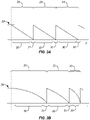
- FIGS. 3A and 3B are graphical representations of a portion of a typical diffractive profile of a multifocal lens. While the graph shows only 3 full echelettes, typical diffractive lenses extend to at least 9 echelettes to over 32 echelettes.
- FIG 3A the height of the surface relief profile (from a plane perpendicular to the light rays) of each point on the echelette surface is plotted against the square of the radial distance (r 2 or p) from the optical axis of the lens.
- each echelette 23 may have a diameter or distance from the optical axis which is often proportional to ⁇ n, n being the number of the echelette 23 as counted from optical axis 24.
- Each echelette has a characteristic optical zone 30 and transition zone 31.
- Optical zone 30 typically has a shape or downward slope that may be linear when plotted against p as shown in FIG. 3A .
- optical zone 30 When plotted against radius r, optical zone 30 has a shape or downward slope that is parabolic as shown in FIG. 3B .
- all echelettes have the same surface area.
- the area of echelettes 23 determines the add power of lens 20, and, as area and radii are correlated, the add power is also related to the radii of the echelettes.
- transition zone 31 between adjacent echelettes is sharp and discontinuous.
- the height of the lens face sharply transitions from sloping steadily downwards to stepping vertically upwards, and the transitions abruptly back to sloping steadily downwards again.
- echelettes 23 also have a characteristic step height 32 defined by the distance between the lowest point and height point of the echelette.
- the slope (or first derivative) and/or the curvature (second derivative) of the diffractive surface are discontinuous adjacent the transitions.
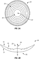
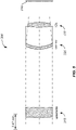
- FIG. 4 provides a graphical representation of a cross section of a single microstructure lens profile 100, according to embodiments of the present invention. Only half of the lens is shown, although since the lens is rotationally symmetric, the other half is a mirror image that complements the lens at the left side of FIG. 4 .
- Profile 100 of the single ring surface includes an inner portion or single ring 110, a step or transition 120, and an outer portion 130. Inner portion 110 extends between a central location 170 of profile 100 and transition 120, and outer portion 130 extends between transition 120 and a peripheral location 180 of profile 100. Central location 170 is typically disposed at the optical axis (although in certain embodiments it may be offset - for example to match the pupil center or an offset eye axis, etc.).
- transition 120 is disposed at a distance of about 1.5 mm from the optical axis
- peripheral location 180 is disposed at the diameter of the clear aperture of the lens, here at a distance of about 3.0 mm from the optical axis.
- transition 120 can be disposed at a distance from the optical axis that is within a range from about 0.5 mm to about 2.0 mm
- peripheral location 180 can be disposed at a distance from the optical axis that is within a range from about 2.0 to about 3.5 mm, or bigger (for example, for contact lenses, the ranges would be approximately 15% larger due to the optically more powerful position of contact lens compared to an IOL; those skilled in the art would appropriately scale certain dimensions depending on the application).
- the surface height or sag (d) from a reference plane perpendicular to the optical axis, of each point on the lens profile is plotted against the radial distance (r) from the optical axis of the lens.
- the value of displacement or total sag (d) can have a value within a range from about 0 mm to about 0.07 mm.
- the total sag can depend on the refractive shape of the surface and can have a value, for an IOL, of typically between 0 mm and about 2 mm, or to about minus 2 mm, in cases where the surface is concave.
- Inner portion or echelette 110 includes a center 110a and a peripheral edge 110b. At center or central section 110a of inner portion 110, the sag (d) of inner portion 110 is substantially equivalent to the displacement or sag (d) of peripheral curve 160. At peripheral edge 110b, the sag (d) of inner portion 110 is substantially equivalent to the sag (d) of diffractive base curve 140. Where radial distance (r) is zero, sag (d) of inner portion 110 is equivalent to the value of the peripheral curve 160.
- inner portion 110 can present a parabolic shape, for example as described in Equation 4a of Cohen, Applied Optics, 31:19, pp. 3750-3754 (1992 ). It is understood that in some instances, inner portion 110 may present any of a variety of shapes or profiles, including hyperbolic shapes, spherical shapes, aspheric, and sinusoidal shapes. The shape of inner portion 110 can be imposed on a refractive shape.
- the value of sag (d) steps or changes from the value of diffractive base curve 140 to the value of peripheral curve 160.
- sag (d) of inner portion 110 is equivalent to the value of the diffractive base curve 140.
- the displacement of the profile 100 approaches that of the peripheral curve 160 as the radial distance increases from a value of zero to a value of about 1.5 mm.
- the value of the offset can be determined along the vertical axis. The offset value may be selected depending on the amount of phase delay.
- the inner portion 110 and the outer portion 130 may not end up at the same vertical height at position 110b/130a.
- the diffractive transition step provides a sharp step in the profile.
- the transition is characterized by a step height having a value within a range from about 0.5 ⁇ m and about 4 ⁇ m.
- a transition can be characterized by a step height having a value within a range of about 1.5 ⁇ m and 2.5 ⁇ m.
- Outer portion 130 includes an inner or central edge 130a and a peripheral edge 130b.
- the sag (d) of outer portion 130 is substantially equivalent to the sag (d) of peripheral curve 160.
- the sag (d) of outer portion 130 remains substantially equivalent to the sag (d) of peripheral curve 160.
- the value of sag (d) for the outer portion 130 of profile 100 between radial distance 1.5 mm and radial distance 3.0 mm is equivalent to the value of peripheral curve 160.
- the sag of the profile 100 and the peripheral curve 160 are approximately equivalent between radial distance values of 1.5 mm and 3.0 mm.
- outer portion 130 can provide a normal spherical or aspherical curve, such as a Tecnis aspheric surface, which corrects or treats the ocular spherical aberration.
- a normal spherical or aspherical curve such as a Tecnis aspheric surface
- a Tecnis aspheric surface For a more detailed description of the Tecnis IOL see U.S. 7,615,073 .
- Virtually any aspheric profile may be used.
- a Tecnis profile, or an aspherical surface that modifies, reduces, or increases the ocular spherical aberration can be used.
- a refractive multifocal surface can also be used, or a refractive aspherical or zonal refractive surface that extends the depth of focus.
- the diffractive multifocal may be on the opposite side.
- embodiments of the present invention encompass lens configurations where such step configurations are absent.
- the size of the human pupil varies with illumination. In bright light the pupil is small, and in dim or low light conditions the pupil is large. In addition, the size of the human pupil varies with accommodative effort. Without accommodative effort, the pupil is larger than with accommodative effort. Hence, for a smaller pupil, it may be desirable to provide a design that places a relative emphasis on intermediate or near vision. For a larger pupil, it may be desirable to provide a design that places a relative emphasis on far vision. Such considerations may affect IOL design.
- the lens may include only a single microstructure ring, so that light separation between distinct foci is not complete, as compared to diffractive multifocal IOLs having multiple echelettes.
- the size of the pupil is small, e.g. between about 1 mm and 2 mm in diameter, and the eye has a large depth of focus (for example from a pinhole effect), almost irrespective of the optics of the IOL.
- Large pupil size e.g. larger than about 4-5 mm in diameter, generally applies to low light conditions, and is often associated with distance vision for which the power of the IOL is typically established. Therefore, many patients would benefit most from an IOL that enhances the depth of focus in order to view at intermediate distances.
- An IOL having a single echelette or ring effectively increases the depth of focus for intermediate pupil sizes, while maintaining the general increased depth of focus of small pupil sizes, and also maintaining an emphasis on far vision for large pupil sizes.
- the single echelette and the remaining surface area of the optic or remaining lens portion have unequal surface areas for almost all pupil sizes, there is an incomplete split between the foci. Since the split of light is incomplete, the separation of foci is incomplete. This incomplete separation of foci contributes to the extended depth of focus and the attenuation of dysphotopsia (e.g. halos).
- FIG. 4A provides a graphical representation of a portion of a lens diffractive profile according to embodiments of the present invention, which further explains a single microstructure embodiment.
- the height of the surface relief profile (from a plane perpendicular to the light rays) of each point on the echelette surface is plotted against the square of the radial distance (r 2 or p) from the optical axis of the lens.
- the echelette can have a characteristic optical zone 930 and transition zone 931.
- Optical zone 930 can have a shape or downward slope that may be linear when plotted against p as shown in FIG. 4A . When plotted against radius r, optical zone 930 can have a shape or downward slope that is parabolic.
- central optical zone 930 can provide a central parabolic echelette.
- An outer (refractive) zone can follow the base radius with a fixed offset.
- the profile can present an echelette or central portion 923a and a refractive zone or peripheral portion 923b.
- transition zone 931 between the optical zone 930 and the outer zone 933 can be sharp and discontinuous.
- a vertical transition between central portion or echelette 923a and peripheral portion or refractive zone 923b can be sharp and discontinuous.
- the height of the lens face sharply transitions from sloping steadily downwards (e.g. across optical zone 930) to stepping vertically upwards (e.g. at transition zone 931), and the transitions abruptly back to sloping steadily or substantially horizontal.
- echelette 923a or optical zone 930 also has a characteristic step height 932 defined by the distance between the lowest point and highest point of the echelette.
- the slope (or first derivative) and/or the curvature (second derivative) of the diffractive surface are discontinuous adjacent the transition.
- the first derivative can be indicated by the direction of the lines, and the second derivative can be indicated by the curve of the line.
- transition zone 931 which can be referred to as the transition from the echelette to the adjacent zone or zones, can be shaped in a specific way, so as to optimize the optical performance, for example, to minimize scatter from a sharp transition.
- a central portion 923a can be defined as an echelette, and a peripheral portion 923b can be defined as a refractive zone.
- FIG. 4B is a graphical representation of a lens profile disclosing a single echelette surrounding a central refractive zone of the lens.
- the lens profile in FIG. 4B has one single echelette or microstructure 980e, which is positioned as an annulus around a central refractive optical zone 970e.
- the annular echelette has an inner radius 982e and an outer radius 984e, a profile shape 986e and a profile height 988e (offset1).
- the annular echelette 980e may be surrounded by a refractive peripheral zone 990e, having a profile height 998e (offset2).
- Profile heights 988e, 998e may be characterized by their respective distances from the base/central refractive zone.
- the refractive central and peripheral zones can be aspherical surfaces, designed to modify ocular aberrations, e.g. spherical aberration.
- a transition (e.g. vertical line) between a microstructure and a refractive zone may be sharp or smooth, as further described elsewhere herein.
- the refractive zones may be spherical or aspherical, or mixed, having a spherical refractive zone and an aspherical refractive zone.
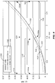
- FIG. 4C provides a graphical representation of a cross section of a single microstructure lens profile 200 on the posterior surface of a lens with a ring diameter of 1.21mm and a stepheight at 220 of 2.05 ⁇ m, corresponding with a phase delay of 0.5 lambda (see table 2).
- the ring diameter was reduced from 1.5mm (which is the inner ring diameter for a 2.0 Diopter conventional IOL diffractive lens) to 1.21mm by a scaling factor ⁇ 2, as described in patent US 5,121,980 (Cohen ). Only the inner portion and part of the outer portion of half of the lens is shown, although since the lens is rotationally symmetric, the other half is a mirror image.
- Profile 200 of the single ring surface includes an inner portion 210 or single ring, a step or transition 220, and an outer portion 230.
- the outer portion 230 extends beyond that disclosed in FIG. 4C to 2 .5mm.
- Inner portion 210 extends between a central location 270 of profile 200 and transition 220.
- Outer portion 230 extends between transition 220 and a peripheral location (not shown).
- the inner portion or echelette 210 includes a center 210a and a peripheral edge 210b.
- the sag (d) of inner portion is between the sag (d) of the diffractive base curve 240 and the sag (d) of the peripheral curve 260 at 1.03 ⁇ m from the peripheral curve 260, corresponding with a phase delay of 0.25 lambda (see table 2).
- the sag (d) of inner portion 210 is substantially equivalent to the sag (d) of diffractive base curve 240 at 13.8 ⁇ m.
- the value of sag (d) steps or changes from the value of diffractive base curve 240 to the value of peripheral curve 260.
- radial distance (r) corresponds to transition 220
- sag (d) of inner portion is equivalent to the value of the diffractive base curve 240.
- the displacement of the profile approaches that of the diffractive base curve as the radial distance increases from a value of zero to a value of about 0.61 mm.
- the stepheight is 2.05 ⁇ m resulting in a phase delay of 0.5.
- the outer portion 230 includes an inner or central edge 230a and a peripheral edge (not shown).
- the sag (d) of outer portion is substantially equivalent to the sag (d) of peripheral curve 260.
- the sag (d) of outer portion remains substantially equivalent to the sag (d) of peripheral curve 260.
- the value of sag (d) for the outer portion of profile between radial distance 0.61 mm and the peripheral portion at radial distance 2.5 mm is equivalent to the value of peripheral curve 260.
- the sag of the profile and the peripheral curve 260 are approximately equivalent between radial distance values of 0.61 mm and 2.5 mm.
- Outer portion can provide a normal spherical or aspherical curve, such as a Tecnis aspheric surface, which corrects or treats the ocular spherical aberration.
- the profile design can be characterized in terms of a set of parameters.
- Conventional multifocal lenses, having a plurality of echelettes are typically characterized by the parameters: add power and light distribution.
- the single echelette of a profile can be described as reflecting a lens add power and a light distribution (as discussed in more detail below).
- Lens add power can be based on the diameter or radial position or location of a profile echelette, and light distribution can be based on the relative height of an echelette.
- the diameter (or size or width or surface area) of the echelette is related to the diffractive power of the lens.
- variations of the geometry of the single echelette design disclosed herein have been characterized according to conventional diffractive IOL design in terms of add power.
- the radius of the single echelette embodiments disclosed herein are equivalent to the inner radius of conventional diffractive IOLs with the same add power.
- the add power would not necessarily describe the optical characteristics of the single echelette embodiments disclosed herein.
- the diffractive power of the lens has a value within a range from about 0.5 diopters to about 3.0 diopters representing the echelette radius and diameter as detailed in Table 1 below.
- Table 1 provides dimensions of various samples, where D represents the power in diopters, R represents the radius of the ring, or echelette, in mm, and De represents the diameter of the ring in millimeters.
- the single echelette is an annulus around, or within, a refractive surface. In such case, a translation between diffractive power and echelette size is represented by the surface area of the echelette.
- Table 1 provides dimensions for surface areas of the echelette. Table 1 D R (mm) De (mm) Area (mm 2 ) 0.5 1.48 3 6.9 1 1.05 2.1 3.5 1.5 0.86 1.7 2.3 2 0.74 1.5 1.7 2.5 0.66 1.3 1.4 3 0.61 1.2 1.2
- the step height or profile height can determine the phase delay or phase shifting profile.
- a greater step height can correspond to a greater phase shift.
- the phase shift is related to the light distribution of the lens.
- variations of the geometry of the single echelette design disclosed herein have been characterized according to conventional diffractive IOL design in terms of light distribution.
- the light distribution would not necessarily describe the optical characteristics of the single echelette embodiments disclosed herein.
- a lens can include a transition characterized by a step height producing a phase shift between about 0.25 and about 1 times the design wavelength.
- a diffractive profile can be characterized by a design wavelength
- the lens can include a transition characterized by a step height producing a phase shift between about 0.15 and about 2 times the design wavelength.
- the lens may include a transition characterized by a step height producing a phase shift of about 0.5.
- the lens may include a transition characterized by a step height of about 0.4.
- Table 2 provides dimensions of various samples disclosing the relationship between phase delay (in wavelengths) and step height (in ⁇ m), as valid for an example IOL material.
- Table 2 Phase Delay Stepheight 0.896 3.68 0.700 2.87 0.590 2.42 0.509 2.09 0.500 2.05 0.423 1.74 0.366 1.50 0.350 1.44 0.250 1.03 0.150 0.62
- the radius of the single ring would be 0.66 mm and the stepheight would be 1.74 ⁇ m.
- the single ring central or single central echelette design has an optical performance that depends on the pupil size.
- the echelette will act as a refractive lens, having a very large depth of focus, due to the pinhole effect.
- the lens will act as a diffractive/refractive lens, with an appropriate phase shift.
- the size of the central echelette influences the pupil dependence of the lens. As such, the size of the central echelette can be chosen, depending on the pupil sizes of a specific patient.
- the pupil sizes of a patient may be measured in bright light, in dim light, during far vision and during near vision, and in the different combinations of light level and accommodative effort.
- These different pupil sizes which may be defined as pupil dynamics, can be used as input parameters for an optimal design of the single ring or single echelette design.
- the size of the central echelette may be selected to be smaller than 2 mm (e.g. outer diameter of the circular echelette of FIG. 4A ), as to provide adequate near and/or intermediate vision.
- the size of the central echelette may chosen 2 mm or larger, as to provide adequate near and intermediate vision.
- the diameter of the central echelette can be smaller than the smallest pupil size the patient has under any condition (e.g. bright/dim light; near/far vision).
- the size, the profile, and the offsets may be chosen to maximize the lens performance for that specific patient, or group of patients.
- this is a trade off between the different vision circumstances (combinations of light level and accommodative effort) at which the pupil of the patient is measured.
- exemplary embodiments include a method of designing an ophthalmic lens comprised of utilizing pupil size measurements and based on the measurements determining the size of an isolated echelette to impose on the surface of a lens.
- the pupil size measurements may be based on a group of patients.
- the central echelette has been varied in size, and step height (offset).
- variations of the echelette design have been characterized according to conventional diffractive IOL design in terms xD/y%, where xD represents the add power that the echelette design represents (e.g. based on echelette size and/or position, and step height), and y% represents the portion of the light directed into the first order focus.
- xD represents the add power that the echelette design represents (e.g. based on echelette size and/or position, and step height)
- y% represents the portion of the light directed into the first order focus.
- the add power and light distribution are being used herein to characterize the geometry of the central echelette.
- the radius of the single echelette embodiments disclosed herein are equivalent to the inner radius of conventional diffractive IOLs with the same add power.
- the step height and associated phase delay of the single echelette embodiments disclosed herein are equivalent to the step height/ phase delay of conventional diffractive IOLs with the same light distribution.
- the add power and light distribution would not describe the optical characteristics of the single echelette embodiments as disclosed herein.
- Table 3 discloses the relationship between percentage of light between near and far focus, phase delay, and stepheight for the IOL material in the example.
- Table 3 Percent Near Phase Delay Stepheight 99 0.896 3.68 85 0.700 2.87 68 0.590 2.42 52 0.509 2.09 50 0.500 2.05 35% 0.423 1.74 25 0.366 1.50 23 0.350 1.44 10 0.250 1.03 3 0.150 0.62
- a 2D/35% echelette design represents a lens with a central echelette with a radius of 0.74, wherein the phase delay is 0.423 and the stepheight is 1.74. Similar nomenclature is used in conjunction with the designs as analyzed in FIGS. 6-20 herein.
- FIG. 5 illustrates an optical system layout 300 of a schematic eye that includes a spectacle lens 310, a cornea 320, an intraocular lens 330, and a retina 340.
- the cornea 320 has the spherical aberration of an average cataract patient.
- the schematic eye also has the average chromatic aberration of the human eye.
- This so called ACE model or average cornea eye model, is based on actual wavefront measurements collected from a sampling of cataract patients, and chromatic aberration and dispersion of the human eye.
- the eye model is substantially described in: Norrby, S., Piers, P., Campbell, C., & van der Mooren, M. (2007) Model eyes for evaluation of intraocular lenses. Appl Opt, 46 (26), 6595-6605 .
- Using the ACE model it is possible to evaluate various lens profiles.
- By changing the power of the spectacle lens it is possible to generate various defocus curves.
- a negative power spectacle lens can mimic the effect of looking at an object at a
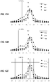
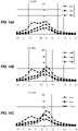
- FIGS. 6A to 9D a number of variations have been analyzed, and the image quality versus defocus has been calculated in the ACE eye model.
- the image analysis is carried out for pupil diameters of 2.0 mm, 3.0 mm, and 4.0 mm. This is depicted in FIGS. 6A to 9D , and FIGS. 10A to 13C .
- FIGS. 6A to 9D and FIGS. 10A to 13C can be considered as a single set.
- the size of the echelette is being varied from 1.2 mm to 3.0mm in diameter, and the step height is being varied from 0.6 to 3.7 ⁇ m.
- the echelette geometry in this series is characterized in terms xD/y%.
- the general lens configuration was an equi-biconvex optic, having an aspherical anterior surface and a spherical posterior surface.
- the single ring design was applied onto the posterior surface.
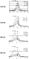
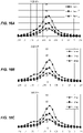
- FIGS. 5A -5C can serve as a reference.
- FIG. 5A shows a regular aspherical design, correcting the corneal spherical aberration.
- FIG. 5B shows a regular spherical design.
- FIG. 5C shows a regular diffractive multifocal design, having a 4-diopter add power. It should be noted that the diffractive multifocal IOL of FIG. 5C has a second peak, that is not shown, as it is outside the horizontal scale of the graph. The second peak is similar to the first peak in shape, height, and width.
- the horizontal (x-) axis denotes the amount of defocus, expressed in diopters of spectacle power.
- the left half of the figures, corresponding to minus spectacle powers, represent the situation in which the spectacle makes the eye myopic.
- the right half of the figure, corresponding to positive spectacle power, represents the situation in which the spectacle makes the eye hyperopic.
- the vertical (y-) axis denotes image quality, presented by the volume under the white-light MTF curve, as a percentage of the volume under the white-light diffraction limited MTF. As such, it is used as a measure of retinal image quality.
- the left part of the figure represents the image quality for near and intermediate vision, corresponding to spectacle powers up to -2.5D.
- an echelette design representing a 0.5D add may provide little benefit over a regular monofocal lens.
- Other designs indicate some benefit by having an extended depth of focus for at least some of the pupil sizes. None of the single echelette designs, although their echelette is designed as having an add power, show two fully separated peaks (with zero MTF Volume in-between the peaks), such as for the multifocal IOL shown in FIG. 5C . Many designs, although their echelette is designed as having an add power, do not show two separate peaks in the defocus curve, as would be typical for multifocal designs. For example, FIGS.
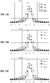
- FIGS. 14A to 17C illustrate further evaluations of the profile designs referenced in FIGS. 10A to 12C , in a computer model of a "physical eye" of an actual patient.
- This computer model incorporates optical higher order aberrations from the cornea of the patient.
- the methodology of the eye model is described in: Piers, P. A., Weeber, H. A., Artal, P. & Norrby, S. "Theoretical comparison of aberration-correcting customized and aspheric intraocular lenses” J Refract Surg 23, 374-84 (2007 ).
- the "physical eye” model is associated with a better prediction of the optical performance of IOL designs in the patient.
- FIGS. 14A to 17C can be described as one set.
- the size of the echelette is being varied from about 1.2 mm to 1.5 mm in diameter, and the step height is being varied from 0.6 to 1.7 ⁇ m.
- the echelette geometry in this series is characterized in terms xD/y%.
- the general lens configuration was an equi-biconvex optic, having a Tecnis aspherical anterior surface and a spherical posterior surface.
- the single ring design was applied onto the posterior surface.
- the design profiles were assessed for a 2 mm pupil, a 3 mm pupil, and a 4 mm pupil.
- FIGS. 18A through 18C can be described as the reference.
- FIG. 18A shows a regular aspherical design, correcting the corneal spherical aberration. The evaluation of this design profile is assessed for a 2 mm pupil, a 3 mm pupil, and a 4 mm pupil.
- FIG. 18B shows a regular spherical design. The evaluation of this spherical IOL design profile is assessed for a 2 mm pupil, a 3 mm pupil, and a 4 mm pupil.
- FIG. 18C can be characterized as a diffractive multifocal +4D, similar to that described in FIG. 5C .
- general trends as seen in the ACE model are also valid in the physical eye model. Many designs exhibit an extended depth of focus, when compared to the regular monofocal IOLs. Where there is a dip in the image quality between the far and near focus, for example at FIG. 10A versus FIG. 14A , FIG. 11A versus FIG. 15A , FIG. 11B versus FIG. 15B , FIG. 11C versus FIG. 15C , FIG. 12B versus FIG. 16B , and FIG. 12C versus FIG. 16C , the magnitude of this dip is reduced. The results indicate that these options deliver a certain image quality over a range of distances, without dropping significantly at some intermediate distance.
- a lens may provide an MTF volume of at least about 35% throughout a range from about -1.25 to about 0.25 for a 2.0 mm pupil.
- a lens can provide an MTF volume of at least 35% over a continuous range of at least about 1.5D for a 2.0 mm pupil.
- Certain embodiments of the present invention provide for an MTF volume of at least 35% over a continuous range of at least about 0.75D.
- Other embodiments can provide an MTF volume of at least 35% over a continuous range of at least about 1.0D. More preferably, embodiments can provide an MTF volume of at least 35% over a continuous range of at least 1.25D.
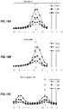
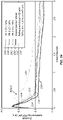
- FIGS. 19A and 19B show measured defocus curves of samples pertaining to a 3 mm pupil ( FIG. 19A ) and a 5 mm pupil ( FIG. 19B ). These samples correspond to single ring IOL, or single ring echelette, similar to that described in FIGS. 21 and 22 .
- the horizontal axis denotes the defocus value in the spectacle plane, in diopters.
- the vertical axis denotes the modulus (MTF) at 50 cycles per millimeter.
- the graphs demonstrate that the actual lenses, as made according to the respective designs, exhibit the extension of the depth of focus at minus defocus values.
- a lens may provide an MTF at 50 cycles per millimeter of at least about 15 throughout a range from about -1.0 to about 0.5 for a 3.0 mm pupil.
- a lens can provide an MTF at 50 cycles per millimeter of at least 15 over a continuous range of at least about 1.5D for a 3.0 mm pupil.
- Certain embodiments provide an MTF at 50 cycles per millimeter of at least 15 over a continuous range of at least 1.0D.
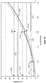
- FIGS. 20A - 20C show measured defocus curves in the ACE eye model of an exemplary embodiment disclosed in section 4 with a ring diameter of 1.21mm and a phase delay of 1 ⁇ 2 wavelength.
- the horizontal axis denotes the defocus value in the spectacle plane, in diopters.
- the vertical axis denotes the modulus (MTF) at 100 cycles per millimeter. Data for 3mm, 4mm, and 5mm pupil diameters are included.
- a lens may provide an MTF at 100 cycles per millimeter of at least about 7 throughout a range from about - 1.0 to about 0.8 for a 3.0 mm pupil.
- a lens can provide an MTF at 100 cycles per millimeter of at least 7 over a continuous range of at least about 1.8D for a 3.0 mm pupil. Certain embodiments provide an MTF at 100 cycles per millimeter of at least 7 over a continuous range of at least 1.5D.
- the graphs demonstrate that the actual lenses, as made according to the respective designs, exhibit the extension of the depth of focus.
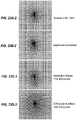
- FIG. 21 shows an exemplary diffractive single ring IOL wherein the geometry is characterized by a 1.0D/100% design profile.
- FIG. 22 shows an exemplary diffractive single ring IOL wherein the geometry is characterized by a 2.0D/10% design profile.
- single microstructure can refer to the fact that, when viewed macroscopically, for example as shown in FIGS. 21-22, just one single ring is visible on the surface. In other words, there is one optical phase transition on the whole optical surface.
- the term single microstructure can refer to the fact that the lens has only one single echelette, represented by the inner portion of the lens surface.
- the single echelette is an annulus around a central portion of the lens. An annulus echelette can have two phase transitions, one at the inner radius of the echelette, and one at the outer radius of the echelette.
- IOLs such as the exemplary embodiments depicted in FIGS. 21-22 can be made of an acrylic material.
- An echelette can be placed on the posterior or anterior surface, and the peripheral zone may be aspherical.
- the opposing surface may be aspherical (e.g. correcting corneal spherical aberration).
- Table 4 below provides dimensions of various samples, where De represents the diameter of the ring, or echelette, in millimeters, and stepheight represents the height of the profile, in ⁇ m.
- De represents the diameter of the ring, or echelette, in millimeters
- stepheight represents the height of the profile, in ⁇ m.
- the single echelette design geometry is characterized in terms of conventional diffractive IOL nomenclature regarding add power and percentage of light. The lenses were tested in the ACE model, using white light.
- Table 4 Name De (mm) step height ( ⁇ m) 1.0D/100% 2.10 3.7 1.5D/30% 1.71 1.7 2.0D/30% 1.48 1.7 2.0D/10% 1.48 1.0
- FIGS. 23A-1 to 23D-2 and 24 show measured performance of dysphotopsia (e.g. halo effects) of samples for a 4.0mm pupil, in an ACE eye model. These figures are based on the image of an extended light source of white light, representing the headlight of a car at a distance of about 50 meters, and correspond to IOL samples, or measurements on real lenses.
- FIG. 23A-1 shows the image generated by the light source, illustrating the appearance of the halo of a 2.0D/30% design.
- FIG. 23B-1 shows the image of an aspherical monofocal.
- FIG. 23C-1 shown the image of a refractive bifocal lens with a +1D add power.
- FIG. 23D-1 shows the image of a diffractive multifocal lens with a 4D add power.
- FIGS. 23A-2, 23B-2, 23C-2, and 23D-2 provide negative images of FIGS. 23A-1, 23B-1, 23C-1, and 23D-1, respectively, for better visibility.
- FIG. 24 shows a graphical representation of the measured light scatter (straylight) corresponding to the light source images of FIGS. 23A-1, 23B-1, 23C-1, and 23D-1.
- the horizontal axis denotes the visual angle, in degrees
- the vertical axis denotes the amount of scatter, represented by the scatter parameter.
- the scatter parameter is defined as the logarithm of the light energy times the square of the visual angle.
- the size of the halo, as shown in FIGS. 37A-1, 37B-1, 37C-1, and 37D-1 in the straylight graph of FIG. 24 is between zero and about 0.5 degrees.
- the peak is part of the halo. In other words, pure straylight is measured for visual angles above 0.5 degrees.
- FIG. 24 shows the straylight of the 1.5D/30% design (line 23A), the 2.0D/30% design (line 23B), and the 2.0D/10% design (line 23C). The amount of straylight is substantially the same for these three designs.
- FIG. 24 also shows the straylight image corresponding to an aspherical monofocal (line 23D), as well as a refractive bifocal lens with a +1D add power (line 23E), and a diffractive multifocal lens with a 4D add power (line 23F).
- line 23D aspherical monofocal
- line 23E refractive bifocal lens with a +1D add power
- line 23F diffractive multifocal lens with a 4D add power
- FIG. 24 shows that the amount of straylight of the 3 designs having a single echelette is smaller than that of the diffractive multifocal lens, and just slightly higher than that of a regular monofocal lens.
- FIG. 24 also confirms the conclusion from FIGS. 23A-1 to 23D-2 that a design having a single echelette does not produce any significant halos.
- an echelette and outer zone design may be configured so as to reduce the amount of light in predetermined non-functional diffractive orders. Additional aspects of these features are described in document US-A-2009/0268158 . Using the same principles as set forth in the aforementioned application, the amount of light in other diffractive orders can be enhanced, as to aid viewing using those diffractive orders.
- Embodiments of the present invention may be combined with a multifocal lens design, and with that extend the depth of focus of each focus of the multifocal lens.
- embodiments of the present invention may be combined with an accommodating lens design, by which the range of accommodation of the accommodating lens can be extended.
- embodiments of the present invention may be combined with lenses correcting ocular aberrations, like toric lenses, aspherical lenses, lenses correcting chromatic aberrations, and the like.
- Embodiments for correcting chromatic aberrations may, for example, increase the phase delay of the echelettes by a discrete multiple of wavelengths.
- an alternative embodiment may have a phase delay of 1.5, corresponding to a stepheight of 6.15 ⁇ m. This embodiment thus directs the first order diffraction to the far focus, and the second order diffraction establishes the depth of focus at the intermediate and near range.
Claims (10)
- Lentille ophtalmique implantable ou lentille ophtalmique de contact (20) comprenant :une face antérieure (21) et une face postérieure (22), les faces étant disposées autour d'un axe optique (24) ; etune échelette isolée imposée sur la face antérieure (21) ou la face postérieure (22) de manière à former :une partie intérieure (110, 210, 930) comportant un centre (110a, 210a) et un bord périphérique (110b, 210b), la partie intérieure (110, 210, 930) étant l'échelette ;une partie extérieure annulaire réfractive (130, 230, 933) comportant un bord intérieur (130a, 230a) et un bord périphérique (130b) ; etune marche de transition diffractive (120, 220, 931) reliant le bord périphérique (110b, 210b) de la partie intérieure (110, 210) et le bord intérieur (130a, 230a) de la partie extérieure (130, 230), la marche de transition diffractive (120, 220, 931) ayant une hauteur de marche.
- Lentille ophtalmique implantable ou lentille ophtalmique de contact (20) de la revendication 1, dans laquelle la face antérieure (21) et/ou la face postérieure (22) ont un profil torique.
- Lentille ophtalmique implantable ou lentille ophtalmique de contact (20) de la revendication 1, dans laquelle l'échelette (110) est caractérisée par un déphasage constant.
- Lentille ophtalmique implantable ou lentille ophtalmique de contact (20) de la revendication 1, dans laquelle l'échelette (110) est caractérisée par une superficie comprise entre 1 et 7 millimètres carrés.
- Lentille ophtalmique implantable ou lentille ophtalmique de contact (20) de la revendication 4, dans laquelle l'échelette (110) a un diamètre dans une gamme d'environ 1 mm à environ 5 mm.
- Lentille ophtalmique implantable ou lentille ophtalmique de contact de la revendication 1 dans laquelle l'échelette (110, 930) est caractérisée par une courbe parabolique.
- Lentille ophtalmique implantable ou lentille ophtalmique de contact (20) de la revendication 1, dans laquelle la partie extérieure (130, 230, 933) est caractérisée par une courbe sphérique ou une courbe asphérique.
- Lentille ophtalmique implantable ou lentille ophtalmique de contact (20) de la revendication 1, dans laquelle la hauteur de marche a une valeur dans une gamme d'environ 0,5 µm à environ 4 µm.
- Lentille ophtalmique implantable ou lentille ophtalmique de contact (20) de la revendication 1, dans laquelle la hauteur de marche a une valeur dans une gamme d'environ 1,5 µm à 2,5 µm.
- Lentille ophtalmique implantable ou lentille ophtalmique de contact de la revendication 8, dans laquelle la hauteur de marche fournit un déphasage compris entre environ 0,25 et environ 3 fois la longueur d'onde de conception.
Priority Applications (1)
| Application Number | Priority Date | Filing Date | Title |
|---|---|---|---|
| EP21200091.3A EP3954327A1 (fr) | 2009-12-18 | 2010-12-17 | Lentille à microstructure unique, systèmes et procédés |
Applications Claiming Priority (2)
| Application Number | Priority Date | Filing Date | Title |
|---|---|---|---|
| US28825509P | 2009-12-18 | 2009-12-18 | |
| PCT/US2010/061017 WO2011075641A2 (fr) | 2009-12-18 | 2010-12-17 | Lentille à microstructure unique, systèmes et procédés associés |
Related Child Applications (2)
| Application Number | Title | Priority Date | Filing Date |
|---|---|---|---|
| EP21200091.3A Division-Into EP3954327A1 (fr) | 2009-12-18 | 2010-12-17 | Lentille à microstructure unique, systèmes et procédés |
| EP21200091.3A Division EP3954327A1 (fr) | 2009-12-18 | 2010-12-17 | Lentille à microstructure unique, systèmes et procédés |
Publications (2)
| Publication Number | Publication Date |
|---|---|
| EP2512371A2 EP2512371A2 (fr) | 2012-10-24 |
| EP2512371B1 true EP2512371B1 (fr) | 2022-04-13 |
Family
ID=43708275
Family Applications (5)
| Application Number | Title | Priority Date | Filing Date |
|---|---|---|---|
| EP10801327.7A Active EP2512372B1 (fr) | 2009-12-18 | 2010-12-17 | Lentille ophtalmique doté d'un retard de phase variable et angulaire |
| EP10793126.3A Active EP2512370B1 (fr) | 2009-12-18 | 2010-12-17 | Lentille à échelette limitée |
| EP21200091.3A Pending EP3954327A1 (fr) | 2009-12-18 | 2010-12-17 | Lentille à microstructure unique, systèmes et procédés |
| EP10798906.3A Active EP2512371B1 (fr) | 2009-12-18 | 2010-12-17 | Lentille à microstructure unique |
| EP20202865.0A Pending EP3824846A1 (fr) | 2009-12-18 | 2010-12-17 | Lentille à échelette limitée |
Family Applications Before (3)
| Application Number | Title | Priority Date | Filing Date |
|---|---|---|---|
| EP10801327.7A Active EP2512372B1 (fr) | 2009-12-18 | 2010-12-17 | Lentille ophtalmique doté d'un retard de phase variable et angulaire |
| EP10793126.3A Active EP2512370B1 (fr) | 2009-12-18 | 2010-12-17 | Lentille à échelette limitée |
| EP21200091.3A Pending EP3954327A1 (fr) | 2009-12-18 | 2010-12-17 | Lentille à microstructure unique, systèmes et procédés |
Family Applications After (1)
| Application Number | Title | Priority Date | Filing Date |
|---|---|---|---|
| EP20202865.0A Pending EP3824846A1 (fr) | 2009-12-18 | 2010-12-17 | Lentille à échelette limitée |
Country Status (8)
| Country | Link |
|---|---|
| US (9) | US8430508B2 (fr) |
| EP (5) | EP2512372B1 (fr) |
| JP (2) | JP2013514833A (fr) |
| CN (2) | CN102892380B (fr) |
| AU (3) | AU2010330809B2 (fr) |
| BR (2) | BR112012014908A2 (fr) |
| CA (3) | CA2784771C (fr) |
| WO (3) | WO2011075641A2 (fr) |
Families Citing this family (77)
| Publication number | Priority date | Publication date | Assignee | Title |
|---|---|---|---|---|
| US8974526B2 (en) | 2007-08-27 | 2015-03-10 | Amo Groningen B.V. | Multizonal lens with extended depth of focus |
| US9216080B2 (en) | 2007-08-27 | 2015-12-22 | Amo Groningen B.V. | Toric lens with decreased sensitivity to cylinder power and rotation and method of using the same |
| US9724190B2 (en) * | 2007-12-13 | 2017-08-08 | Amo Groningen B.V. | Customized multifocal ophthalmic lens |
| ATE523810T1 (de) | 2008-02-15 | 2011-09-15 | Amo Regional Holdings | System, brillenglas und verfahren zur erweiterung der fokustiefe |
| US8862447B2 (en) | 2010-04-30 | 2014-10-14 | Amo Groningen B.V. | Apparatus, system and method for predictive modeling to design, evaluate and optimize ophthalmic lenses |
| EP4109168A1 (fr) * | 2008-07-15 | 2022-12-28 | Alcon Inc. | Lentille à profondeur étendue (edof) une lentille pour augmenter une pseudo-accommodation |
| EP3552587A1 (fr) | 2008-12-22 | 2019-10-16 | Medical College of Wisconsin, Inc. | Procédé et appareil permettant de limiter la croissance de la longueur de l'oeil |
| NL2002540C2 (en) * | 2009-02-17 | 2010-08-18 | Oculentis B V | Ophthalmic lens with optical sectors. |
| CA2784771C (fr) | 2009-12-18 | 2018-12-04 | Hendrik A. Weeber | Lentille a microstructure unique, systemes et procedes associes |
| US8531783B2 (en) | 2010-02-09 | 2013-09-10 | Xceed Imaging Ltd. | Imaging method and system for imaging with extended depth of focus |
| WO2012073112A1 (fr) | 2010-12-01 | 2012-06-07 | Amo Groningen B.V. | Verre progressif possédant une progression de puissance d'addition optique, et système et procédé l'utilisant |
| US9931200B2 (en) | 2010-12-17 | 2018-04-03 | Amo Groningen B.V. | Ophthalmic devices, systems, and methods for optimizing peripheral vision |
| WO2012092584A1 (fr) | 2010-12-30 | 2012-07-05 | AMO Wavefront Sciences LLC. | Méthode de planification améliorée d'un traitement et système de contrôle d'une intervention de chirurgie réfractive laser |
| US10582846B2 (en) | 2010-12-30 | 2020-03-10 | Amo Wavefront Sciences, Llc | Method and system for eye measurements and cataract surgery planning using vector function derived from prior surgeries |
| US10582847B2 (en) | 2010-12-30 | 2020-03-10 | Amo Wavefront Sciences, Llc | Method and system for eye measurements and cataract surgery planning using vector function derived from prior surgeries |
| US10583039B2 (en) | 2010-12-30 | 2020-03-10 | Amo Wavefront Sciences, Llc | Method and system for eye measurements and cataract surgery planning using vector function derived from prior surgeries |
| CA2846235A1 (fr) * | 2011-08-24 | 2013-02-28 | Amo Groningen B.V. | Dispositifs ophtalmiques, systemes et procedes d'optimisation de vision peripherique |
| EP2813882B1 (fr) * | 2012-02-09 | 2021-04-14 | Menicon Co., Ltd. | Lentille ophtalmique multifocale et son procédé de fabrication |
| TWI588560B (zh) | 2012-04-05 | 2017-06-21 | 布萊恩荷登視覺協會 | 用於屈光不正之鏡片、裝置、方法及系統 |
| US9151967B2 (en) * | 2012-05-24 | 2015-10-06 | Jonathan W. Parrelli | Contact lenses |
| AU2013308109B2 (en) * | 2012-08-31 | 2018-04-19 | Amo Groningen B.V. | Multi-ring lens, systems and methods for extended depth of focus |
| US9201250B2 (en) | 2012-10-17 | 2015-12-01 | Brien Holden Vision Institute | Lenses, devices, methods and systems for refractive error |
| EP2908773B1 (fr) | 2012-10-17 | 2024-01-03 | Brien Holden Vision Institute | Lentilles, dispositifs, procédés et systèmes pour erreur de réfraction |
| AU2013353764B2 (en) | 2012-12-04 | 2018-12-06 | Amo Groningen B.V. | Lenses systems and methods for providing binocular customized treatments to correct presbyopia |
| CN104838306B (zh) * | 2012-12-12 | 2016-12-21 | 埃西勒国际通用光学公司 | 用于优化菲涅耳光学镜片的方法 |
| EP2908777B1 (fr) * | 2012-12-18 | 2017-08-02 | Novartis AG | Système pour fournir une lentille intraoculaire ayant une profondeur de champ améliorée |
| CA2875873C (fr) | 2013-03-11 | 2022-06-21 | Abbott Medical Optics Inc. | Lentille intraoculaire qui fait correspondre une surface d'image a une forme retinienne, et procede de conception associe |
| US8974055B2 (en) * | 2013-03-15 | 2015-03-10 | Johnson & Johnson Vision Care, Inc. | Method and apparatus for encapsulating a rigid insert in a contact lens for correcting vision in astigmatic patients |
| DE102013216020A1 (de) * | 2013-08-13 | 2015-02-19 | Carl Zeiss Meditec Ag | Augenlinse mit einem torisch brechenden Oberflächenprofil und eine in radialer Richtung gestufte Oberflächenstruktur |
| CA2916561A1 (fr) | 2013-11-26 | 2015-06-04 | Abbott Medical Optics Inc. | Systeme et procede pour mesurer une dysphotopsie |
| WO2016038470A2 (fr) | 2014-03-10 | 2016-03-17 | Amo Groningen B.V. | Lentille intra-oculaire formant doublet qui améliore la vision globale en cas de perte localisée de la fonction rétinienne |
| DE102014004381B4 (de) * | 2014-03-26 | 2023-08-10 | Rodenstock Gmbh | Verbesserte ophthalmische Linse zur Presbyopie-Korrektion sowie Verfahren zum Herstellen und Vorrichtung |
| CA2946356C (fr) | 2014-04-21 | 2022-09-20 | Amo Groningen B.V. | Dispositifs ophtalmiques, systeme et procedes qui ameliorent la vision peripherique |
| US9335564B2 (en) * | 2014-05-15 | 2016-05-10 | Novartis Ag | Multifocal diffractive ophthalmic lens using suppressed diffractive order |
| WO2016040935A1 (fr) | 2014-09-14 | 2016-03-17 | Lai, Ming | Caméra de fond d'œil à grand champ |
| US11696823B2 (en) * | 2015-04-14 | 2023-07-11 | Z Optics, Inc. | High definition and extended depth of field intraocular lens |
| EP3328265A1 (fr) | 2015-07-27 | 2018-06-06 | AMO WaveFront Sciences, LLC | Systèmes d'imagerie et de mesure optique et procédés pour la chirurgie de la cataracte et la planification de traitement |
| WO2017035296A1 (fr) * | 2015-08-25 | 2017-03-02 | Indiana University Research And Technology Corporation | Systèmes et procédés pour spécifier la qualité d'une image rétinienne sur l'ensemble du champ visuel |
| US10838233B2 (en) | 2015-12-15 | 2020-11-17 | University Of Rochester | Refractive corrector incorporating a continuous central phase zone and peripheral phase discontinuities |
| US20170188825A1 (en) * | 2015-12-30 | 2017-07-06 | Novartis Ag | Extended depth of focus contact lens for vitreoretinal surgery |
| EP3413839A1 (fr) | 2016-02-09 | 2018-12-19 | AMO Groningen B.V. | Lentille intraoculaire progressive et ses procédés d'utilisation et de fabrication |
| US11083566B2 (en) | 2016-02-29 | 2021-08-10 | Alcon Inc. | Ophthalmic lens having an extended depth of focus |
| US9968440B2 (en) * | 2016-02-29 | 2018-05-15 | Novartis Ag | Ophthalmic lens having an extended depth of focus |
| CA3017293A1 (fr) | 2016-03-11 | 2017-09-14 | Amo Groningen B.V. | Lentilles intraoculaires ameliorant la vision peripherique |
| CA3021474A1 (fr) | 2016-04-19 | 2017-10-26 | Amo Groningen B.V. | Dispositifs ophtalmiques, systeme et procedes qui ameliorent la vision peripherique |
| CN115185103A (zh) | 2016-08-01 | 2022-10-14 | 华盛顿大学 | 用于治疗近视的眼科镜片 |
| US11013594B2 (en) | 2016-10-25 | 2021-05-25 | Amo Groningen B.V. | Realistic eye models to design and evaluate intraocular lenses for a large field of view |
| US9933633B1 (en) | 2016-11-08 | 2018-04-03 | Paul Douglas Becherer | Bifocal contact lenses providing reduced glare and blurriness in dim lighting |
| US10531950B2 (en) * | 2016-11-16 | 2020-01-14 | Tatvum LLC | Intraocular lens having an extended depth of focus |
| US10426599B2 (en) | 2016-11-29 | 2019-10-01 | Novartis Ag | Multifocal lens having reduced chromatic aberrations |
| US10932901B2 (en) | 2017-02-10 | 2021-03-02 | University Of Rochester | Vision correction with laser refractive index changes |
| WO2018167302A1 (fr) * | 2017-03-17 | 2018-09-20 | Amo Groningen B.V. | Lentilles intraoculaires de diffraction permettant une plage de vision étendue |
| US10739227B2 (en) | 2017-03-23 | 2020-08-11 | Johnson & Johnson Surgical Vision, Inc. | Methods and systems for measuring image quality |
| WO2018208724A1 (fr) | 2017-05-08 | 2018-11-15 | Sightglass Vision, Inc. | Lentilles de contact pour la réduction de la myopie et leurs procédés de fabrication |
| US11523897B2 (en) | 2017-06-23 | 2022-12-13 | Amo Groningen B.V. | Intraocular lenses for presbyopia treatment |
| AU2018292030B2 (en) | 2017-06-28 | 2024-02-08 | Amo Groningen B.V. | Extended range and related intraocular lenses for presbyopia treatment |
| US11262598B2 (en) | 2017-06-28 | 2022-03-01 | Amo Groningen, B.V. | Diffractive lenses and related intraocular lenses for presbyopia treatment |
| US11327210B2 (en) | 2017-06-30 | 2022-05-10 | Amo Groningen B.V. | Non-repeating echelettes and related intraocular lenses for presbyopia treatment |
| CA3082053A1 (fr) | 2017-11-30 | 2019-06-06 | Amo Groningen B.V. | Lentilles intraoculaires permettant d'ameliorer l'independance vis a vis des lunettes apres une intervention chirurgicale et leurs procedes de fabrication |
| US10884264B2 (en) * | 2018-01-30 | 2021-01-05 | Sightglass Vision, Inc. | Ophthalmic lenses with light scattering for treating myopia |
| AU2019394013A1 (en) | 2018-12-06 | 2020-12-03 | Amo Groningen B.V. | Diffractive lenses for presbyopia treatment |
| US11360325B2 (en) | 2019-02-11 | 2022-06-14 | Johnson & Johnson Vision Care, Inc | Employing diffractive structure to reduce soft contact lens variation |
| TW202125041A (zh) * | 2019-12-18 | 2021-07-01 | 瑞士商愛爾康公司 | 衍射與折射混合式接觸透鏡 |
| AU2020416055A1 (en) | 2019-12-30 | 2022-08-25 | Amo Groningen B.V. | Lenses having diffractive profiles with irregular width for vision treatment |
| US11886046B2 (en) | 2019-12-30 | 2024-01-30 | Amo Groningen B.V. | Multi-region refractive lenses for vision treatment |
| AU2020416508A1 (en) | 2019-12-30 | 2022-08-25 | Amo Groningen B.V. | Achromatic lenses with zone order mixing for vision treatment |
| AU2020418360A1 (en) | 2019-12-30 | 2022-08-25 | Amo Groningen B.V. | Achromatic lenses for vision treatment |
| AU2021356283A1 (en) * | 2020-10-08 | 2023-03-30 | Alcon Inc. | Ophthalmic lens with phase-shift structure and method |
| CN117280252A (zh) | 2021-06-14 | 2023-12-22 | 爱尔康公司 | 多焦点衍射硅氧烷水凝胶接触镜片 |
| US20230011320A1 (en) | 2021-07-09 | 2023-01-12 | Amo Groningen B.V. | Diffractive lenses for range of vision |
| WO2023036841A1 (fr) | 2021-09-08 | 2023-03-16 | Amo Groningen B.V. | Lentilles à profils de diffraction ayant une rugosité de surface élevée |
| CN114137640B (zh) * | 2021-11-09 | 2023-02-03 | 江西欧迈斯微电子有限公司 | 自由曲面透镜、菲涅尔透镜及可穿戴设备 |
| WO2023099745A1 (fr) | 2021-12-03 | 2023-06-08 | Amo Groningen B.V. | Lentilles ayant une conception multi-anneaux pour le traitement de la vision |
| US20230190451A1 (en) | 2021-12-03 | 2023-06-22 | Amo Groningen B.V. | Lenses having diffractive profiles with parabolic transition zones |
| WO2023131647A1 (fr) | 2022-01-06 | 2023-07-13 | Amo Groningen B.V. | Composants optiques télescopiques destinés à évaluer les effets photiques de lentilles intraoculaires |
| US20230236439A1 (en) * | 2022-01-21 | 2023-07-27 | Coopervision International Limited | Myopia-control contact lenses and methods relating thereto |
| WO2023148170A1 (fr) | 2022-02-01 | 2023-08-10 | Amo Groningen B.V. | Lentilles diffractives à décalage d'ordre diffractif |
Citations (1)
| Publication number | Priority date | Publication date | Assignee | Title |
|---|---|---|---|---|
| US20010035935A1 (en) * | 1995-03-03 | 2001-11-01 | Vision-Ease Lens, Inc. | Production of optical elements |
Family Cites Families (276)
| Publication number | Priority date | Publication date | Assignee | Title |
|---|---|---|---|---|
| US2077092A (en) | 1936-01-13 | 1937-04-13 | Broder Simon | Ophthalmic lens |
| US2771550A (en) | 1953-03-09 | 1956-11-20 | Marchant Calculators Inc | Counting circuits |
| GB1054972A (fr) | 1963-02-22 | |||
| US3305294A (en) | 1964-12-03 | 1967-02-21 | Optical Res & Dev Corp | Two-element variable-power spherical lens |
| US3735685A (en) | 1971-05-07 | 1973-05-29 | Polaroid Corp | Reflective imaging apparatus |
| US4093361A (en) | 1971-11-15 | 1978-06-06 | Precision Cosmet Co., Inc. | Composite prosthetic polymeric devices |
| US4010496A (en) | 1975-10-01 | 1977-03-08 | Neefe Charles W | Bifocal lens which positions within the anterior chamber |
| US4077071A (en) | 1976-03-15 | 1978-03-07 | Freeman Jerre M | Neutral buoyancy intraocular lens device |
| US4134160A (en) | 1977-03-16 | 1979-01-16 | Bayers Jon Herbert | Intraocular lens |
| US4162122A (en) | 1977-09-14 | 1979-07-24 | Cohen Allen L | Zonal bifocal contact lens |
| US4210391A (en) | 1977-09-14 | 1980-07-01 | Cohen Allen L | Multifocal zone plate |
| US4174543A (en) | 1978-06-01 | 1979-11-20 | Kelman Charles D | Intraocular lenses |
| US4340283A (en) | 1978-12-18 | 1982-07-20 | Cohen Allen L | Phase shift multifocal zone plate |
| US4338005A (en) * | 1978-12-18 | 1982-07-06 | Cohen Allen L | Multifocal phase place |
| US4254509A (en) | 1979-04-09 | 1981-03-10 | Tennant Jerald L | Accommodating intraocular implant |
| US4254510A (en) | 1979-06-18 | 1981-03-10 | Tennant Jerald L | Implant lens with biarcuate fixation |
| US4316293A (en) | 1979-08-27 | 1982-02-23 | Bayers Jon Herbert | Flexible intraocular lens |
| US4319564A (en) | 1980-01-03 | 1982-03-16 | Karickhoff John R | Instrument for measurement of the diameter of the anterior chamber of the eye |
| US4249272A (en) | 1980-03-05 | 1981-02-10 | Stanley Poler | Intraocular lens |
| USRE32525F1 (en) | 1980-04-01 | 1989-05-09 | Universal intraocular lens and a method of measuring an eye chamber size | |
| US4377873A (en) | 1980-10-30 | 1983-03-29 | Reichert Jr Henry L | Intraocular lens |
| US4480340A (en) | 1981-02-18 | 1984-11-06 | Shepard Dennis D | Intraocular lens with resilient support means |
| DE8107675U1 (de) | 1981-03-03 | 1981-07-30 | Porsche Design Produkte Vertriebsgesellschaft mbH, 5020 Salzburg | "geodreieck" |
| US4370760A (en) | 1981-03-25 | 1983-02-01 | Kelman Charles D | Anterior chamber intraocular lens |
| GB2101764B (en) | 1981-04-29 | 1984-08-30 | Pilkington Perkin Elmer Ltd | Improvements in or relating to artificial eye lenses |
| DE3119002A1 (de) | 1981-05-13 | 1982-12-02 | INPROHOLD Establishment, 9490 Vaduz | Hinterkammer-implantationslinse |
| US4403353A (en) | 1981-06-25 | 1983-09-13 | Tennant Jerald L | Anterior chamber implant lens |
| US4402579A (en) | 1981-07-29 | 1983-09-06 | Lynell Medical Technology Inc. | Contact-lens construction |
| US4446581A (en) | 1981-09-02 | 1984-05-08 | Blake L W | Intraocular lens with free-ended sizing prong |
| US4409691A (en) | 1981-11-02 | 1983-10-18 | Levy Chauncey F | Focussable intraocular lens |
| US4404694A (en) | 1982-03-18 | 1983-09-20 | Kelman Charles D | Intraocular lens |
| US4504982A (en) | 1982-08-05 | 1985-03-19 | Optical Radiation Corporation | Aspheric intraocular lens |
| DE3377535D1 (en) | 1982-10-27 | 1988-09-01 | Pilkington Plc | Bifocal contact lens comprising a plurality of concentric zones |
| US4593981A (en) | 1983-05-06 | 1986-06-10 | Master Contact Lens Labs Inc. | Bifocal contact lens |
| US4500382A (en) | 1983-06-10 | 1985-02-19 | Transilwrap Company, Inc. | Method of manufacture of resin film precision biomedical article |
| US4556998A (en) | 1983-08-04 | 1985-12-10 | Siepser Steven B | Artificial intraocular lenses and method for their surgical implantation |
| DE3431224A1 (de) | 1983-08-04 | 1986-03-06 | Steven B Siepser | Kuenstliche intraokulare linse |
| US4551864A (en) | 1983-08-18 | 1985-11-12 | Iolab Corporation | Anterior chamber lens |
| US4636049A (en) | 1983-09-20 | 1987-01-13 | University Optical Products Co. | Concentric bifocal contact lens |
| US4560383A (en) | 1983-10-27 | 1985-12-24 | Leiske Larry G | Anterior chamber intraocular lens |
| US4687484A (en) | 1983-12-12 | 1987-08-18 | Kaplan Linda J | Anterior chamber intraocular lens |
| GB8404817D0 (en) | 1984-02-23 | 1984-03-28 | Pilkington Perkin Elmer Ltd | Ophthalmic lenses |
| US4605409A (en) | 1984-05-21 | 1986-08-12 | Kelman Charles D | Intraocular lens with miniature optic having expandable and contractible glare-reducing means |
| US4629460A (en) | 1984-06-25 | 1986-12-16 | Dyer Robert L | Intraocular lens |
| US4787904A (en) | 1984-07-06 | 1988-11-29 | Severin Sanford L | Hydrophillic intraocular lens |
| US4629462A (en) | 1984-07-13 | 1986-12-16 | Feaster Fred T | Intraocular lens with coiled haptics |
| SU1311063A1 (ru) | 1984-09-27 | 1988-01-30 | Московский научно-исследовательский институт микрохирургии глаза | Искусственный хрусталик глаза |
| DE3439551A1 (de) | 1984-10-29 | 1986-04-30 | Inprohold Establishment, Vaduz | Einstueckige implantationslinse |
| FI79619C (fi) | 1984-12-31 | 1990-01-10 | Antti Vannas | Intraokulaer lins. |
| US4787903A (en) | 1985-07-24 | 1988-11-29 | Grendahl Dennis T | Intraocular lens |
| US4781717A (en) | 1985-07-24 | 1988-11-01 | Grendahl Dennis T | Intraocular lens |
| US4676791A (en) | 1985-08-01 | 1987-06-30 | Surgidev Corporation | Intraocular lens and method for making same |
| US4687485A (en) | 1985-08-23 | 1987-08-18 | Barnes-Hind, Inc. | Intraocular lens with leg means having compressible regions and/or color |
| US4681102A (en) | 1985-09-11 | 1987-07-21 | Bartell Michael T | Apparatus and method for insertion of an intra-ocular lens |
| US4834751A (en) | 1985-12-04 | 1989-05-30 | Allergan, Inc. | Staking ring for soft IOL |
| CA1283252C (fr) | 1985-12-09 | 1991-04-23 | Albert C. Ting | Partie haptique d'un implant oculaire |
| US5121979A (en) | 1986-05-14 | 1992-06-16 | Cohen Allen L | Diffractive multifocal optical device |
| US4725277A (en) | 1986-05-14 | 1988-02-16 | Precision-Cosmet Co., Inc. | Intraocular lens with tapered haptics |
| US5144483A (en) * | 1986-05-14 | 1992-09-01 | Cohen Allen L | Diffractive multifocal optical device |
| US4676792A (en) | 1986-08-26 | 1987-06-30 | Donald Praeger | Method and artificial intraocular lens device for the phakic treatment of myopia |
| US5225858A (en) | 1987-06-01 | 1993-07-06 | Valdemar Portney | Multifocal ophthalmic lens |
| US5270744A (en) | 1987-06-01 | 1993-12-14 | Valdemar Portney | Multifocal ophthalmic lens |
| US4898461A (en) | 1987-06-01 | 1990-02-06 | Valdemar Portney | Multifocal ophthalmic lens |
| US4828558A (en) | 1987-07-28 | 1989-05-09 | Kelman Charles D | Laminate optic with interior Fresnel lens |
| US4778462A (en) | 1987-08-24 | 1988-10-18 | Grendahl Dennis T | Multiple element zone of focus artificial lens |
| US4795462A (en) * | 1987-08-24 | 1989-01-03 | Grendahl Dennis T | Cylindrically segmented zone of focus artificial lens |
| US4798608A (en) | 1987-08-24 | 1989-01-17 | Grendahl Dennis T | Laminated zone of focus artificial lens |
| US4798609A (en) * | 1987-08-24 | 1989-01-17 | Grendahl Dennis T | Radially segmented zone of focus artificial lens |
| US4834748A (en) | 1987-09-29 | 1989-05-30 | Allergan, Inc. | Method and apparatus for removing corneal tissue |
| US5047052A (en) | 1987-11-06 | 1991-09-10 | Seymour Dubroff | Anterior chamber intraocular lens with four point fixation |
| US4863539A (en) | 1987-11-06 | 1989-09-05 | Optical Radiation Corporation | Haptic attachment for intraocular lenses |
| US4881804A (en) * | 1987-11-12 | 1989-11-21 | Cohen Allen L | Multifocal phase plate with a pure refractive portion |
| US4881805A (en) * | 1987-11-12 | 1989-11-21 | Cohen Allen L | Progressive intensity phase bifocal |
| US5054905A (en) | 1987-11-12 | 1991-10-08 | Cohen Allen L | Progressive intensity phase bifocal |
| US5056908A (en) * | 1987-11-12 | 1991-10-15 | Cohen Allen L | Optic zone phase channels |
| FR2631228B1 (fr) | 1988-05-11 | 1990-08-10 | Domilens Laboratoires | Implant intra-oculaire de chambre anterieure |
| US4932970A (en) | 1988-05-17 | 1990-06-12 | Allergan, Inc. | Ophthalmic lens |
| FR2631713B1 (fr) | 1988-05-19 | 1990-08-31 | Essilor Int | Lentille diffractive a profil mixte |
| CN1020134C (zh) * | 1988-07-20 | 1993-03-17 | 艾伦·L·科恩 | 多焦点光学器件 |
| US4995714A (en) | 1988-08-26 | 1991-02-26 | Cohen Allen L | Multifocal optical device with novel phase zone plate and method for making |
| FR2642855B1 (fr) | 1989-02-06 | 1991-05-17 | Essilor Int | Lentille optique pour la correction de l'astigmatisme |
| US5121980A (en) | 1989-04-19 | 1992-06-16 | Cohen Allen L | Small aperture multifocal |
| US4997442A (en) | 1989-05-04 | 1991-03-05 | Alcon Laboratories, Inc. | Bicomposite intraocular lenses |
| US5078742A (en) | 1989-08-28 | 1992-01-07 | Elie Dahan | Posterior chamber lens implant |
| US5019097A (en) | 1989-11-22 | 1991-05-28 | Allergan, Inc. | Corneal onlay lenses and methods for attaching same |
| US5089023A (en) * | 1990-03-22 | 1992-02-18 | Massachusetts Institute Of Technology | Diffractive/refractive lens implant |
| US5096285A (en) | 1990-05-14 | 1992-03-17 | Iolab Corporation | Multifocal multizone diffractive ophthalmic lenses |
| US5178636A (en) * | 1990-05-14 | 1993-01-12 | Iolab Corporation | Tuned fresnel lens for multifocal intraocular applications including small incision surgeries |
| US5225997A (en) | 1990-06-05 | 1993-07-06 | Sygnus Controls Inc. | Automatic monitoring and remote reporting device |
| US5147397A (en) | 1990-07-03 | 1992-09-15 | Allergan, Inc. | Intraocular lens and method for making same |
| US5117306A (en) * | 1990-07-17 | 1992-05-26 | Cohen Allen L | Diffraction bifocal with adjusted chromaticity |
| US5120120A (en) * | 1990-07-27 | 1992-06-09 | Cohen Allen L | Multifocal optical device with spurious order suppression and method for manufacture of same |
| US5229797A (en) | 1990-08-08 | 1993-07-20 | Minnesota Mining And Manufacturing Company | Multifocal diffractive ophthalmic lenses |
| US5066301A (en) | 1990-10-09 | 1991-11-19 | Wiley Robert G | Variable focus lens |
| US5258025A (en) | 1990-11-21 | 1993-11-02 | Fedorov Svjatoslav N | Corrective intraocular lens |
| US5217491A (en) | 1990-12-27 | 1993-06-08 | American Cyanamid Company | Composite intraocular lens |
| US5133749A (en) | 1991-05-13 | 1992-07-28 | Nordan Lee T | Centrating haptics |
| US5106180A (en) | 1991-05-30 | 1992-04-21 | Robert Marie | Multifocal ophthalmic lens |
| US5147395A (en) | 1991-07-16 | 1992-09-15 | Allergan Inc. | Small incision endocapsulator IOL |
| US5570143A (en) | 1991-08-09 | 1996-10-29 | Capricornia Contact Lens Pty. Ltd. | Toric lens with axis mislocation latitude |
| WO1993007525A1 (fr) | 1991-10-09 | 1993-04-15 | Seiko Epson Corporation | Lentille pour lunettes |
| US5203790A (en) | 1991-11-12 | 1993-04-20 | Henry H. McDonald | Foldable plastic optical lens with reduced thickness light blocking segments, and anchoring means |
| US5184405A (en) | 1991-12-18 | 1993-02-09 | Jonathan Cress | Method and device for fitting toric contact lenses |
| US5201763A (en) | 1992-02-28 | 1993-04-13 | Allergan, Inc. | Thin intraocular lens |
| US5476513A (en) | 1992-02-28 | 1995-12-19 | Allergan, Inc. | Intraocular lens |
| US5197981A (en) | 1992-04-23 | 1993-03-30 | Alcon Surgical, Inc. | Intraocular lens having haptic of specific curvature and proportion |
| US5760871A (en) | 1993-01-06 | 1998-06-02 | Holo-Or Ltd. | Diffractive multi-focal lens |
| US5748282A (en) | 1993-01-27 | 1998-05-05 | Pilkington Barnes Hind, Inc. | Multifocal contact lens |
| US5408281A (en) * | 1993-04-26 | 1995-04-18 | Ciba-Geigy | Multifocal contact lens |
| US5571177A (en) | 1993-06-14 | 1996-11-05 | Allergan | IOL structured for post-operative re-positioning and method for post-operative IOL re-positioning |
| US5502518A (en) | 1993-09-09 | 1996-03-26 | Scient Optics Inc | Asymmetric aspheric contact lens |
| US5433745A (en) | 1993-10-13 | 1995-07-18 | Allergan, Inc. | Corneal implants and methods for producing same |
| JP3745394B2 (ja) | 1994-07-04 | 2006-02-15 | 武敏 鈴木 | 眼内レンズ |
| AU690315B2 (en) | 1994-07-25 | 1998-04-23 | Boehringer Mannheim Gmbh | Metal complexes with charged linker |
| US5699142A (en) * | 1994-09-01 | 1997-12-16 | Alcon Laboratories, Inc. | Diffractive multifocal ophthalmic lens |
| US5620720A (en) | 1994-11-29 | 1997-04-15 | Allergan | Cast molding of intraocular lenses |
| JPH08196507A (ja) | 1995-01-23 | 1996-08-06 | Nikon Corp | 眼科装置 |
| EP1627613B8 (fr) | 1995-02-15 | 2008-09-03 | The Nice Trust, a Trust of the Isle of Man | Lentille intraoculaire d'accommodation présentant des parties haptiques en forme de T |
| IL118065A0 (en) | 1995-05-04 | 1996-08-04 | Johnson & Johnson Vision Prod | Aspheric toric lens designs |
| US5715031A (en) | 1995-05-04 | 1998-02-03 | Johnson & Johnson Vision Products, Inc. | Concentric aspheric multifocal lens designs |
| US5652638A (en) | 1995-05-04 | 1997-07-29 | Johnson & Johnson Vision Products, Inc. | Concentric annular ring lens designs for astigmatism |
| US5801807A (en) | 1995-08-08 | 1998-09-01 | Nikon Corporation | Ophthalmic illumination device having adjustable transmittance member and microscope for operation using the same |
| US5968094A (en) | 1995-09-18 | 1999-10-19 | Emmetropia, Inc. | Compound intraocular lens |
| WO1997012564A1 (fr) | 1995-10-06 | 1997-04-10 | Cumming J Stuart | Lentilles intraoculaires a haptiques fixes |
| US5716403A (en) | 1995-12-06 | 1998-02-10 | Alcon Laboratories, Inc. | Single piece foldable intraocular lens |
| FR2745711B1 (fr) | 1996-03-05 | 1998-05-07 | Ioltechnologie Production | Implant souple formant lentille intraoculaire de chambre posterieure |
| EP0900403B1 (fr) | 1996-03-21 | 2003-05-28 | Sola International Holdings, Ltd. | Lentilles monovision ameliorees |
| FR2748200B1 (fr) | 1996-05-03 | 1998-09-25 | W K Et Associes | Implant intraoculaire monobloc souple |
| US5864378A (en) * | 1996-05-21 | 1999-01-26 | Allergan | Enhanced monofocal IOL or contact lens |
| US6015435A (en) | 1996-10-24 | 2000-01-18 | International Vision, Inc. | Self-centering phakic intraocular lens |
| JP4672092B2 (ja) | 1996-11-20 | 2011-04-20 | イェール ユニバーシティ | 細胞アポトーシスを阻害するタンパク質であるサービビン(Survivin)、およびその調節 |
| DE19724108C1 (de) | 1997-06-09 | 1998-11-19 | Morcher Gmbh | Kapseläquatorring |
| US5928282A (en) | 1997-06-13 | 1999-07-27 | Bausch & Lomb Surgical, Inc. | Intraocular lens |
| JPH1114804A (ja) | 1997-06-27 | 1999-01-22 | Fuji Photo Optical Co Ltd | プラスチックレンズ |
| IL134738A0 (en) | 1997-09-02 | 2001-04-30 | Thieberger Gil | Ophthalmic lens synthesized from its specifications |
| JPH11142614A (ja) * | 1997-11-13 | 1999-05-28 | Olympus Optical Co Ltd | レリーフ型回折光学素子、レリーフ型回折光学素子製造用の型、及び、レリーフ型回折光学素子を用いた光学系 |
| US6129759A (en) | 1997-12-10 | 2000-10-10 | Staar Surgical Company, Inc. | Frosted haptic intraocular lens |
| FR2772489B1 (fr) | 1997-12-16 | 2000-03-10 | Essilor Int | Lentilles ophtalmiques multifocales a aberration spherique variable suivant l'addition et l'ametropie |
| JP4023902B2 (ja) | 1998-04-10 | 2007-12-19 | 株式会社メニコン | トーリック・マルチフォーカルレンズ |
| US6491721B2 (en) | 1998-04-15 | 2002-12-10 | Alcon Manufacturing, Ltd. | Toric intraocular lens material |
| SE510945C2 (sv) | 1998-05-13 | 1999-07-12 | Tormek Ab | Vinkelmätare vid slipning av eggverktyg |
| NZ501422A (en) * | 1998-06-03 | 2003-01-31 | Neurocontrol Corp | Intramuscular stimulation system comprising a plurality of implantable electrodes in combination with a portable device equipped with a memorised set of movements for eliciting a series of muscle responses to prevent muscle atrophy |
| EP1103014A4 (fr) | 1998-08-06 | 2006-09-06 | John B W Lett | Lentilles multifocales aspheriques |
| US6203499B1 (en) | 1998-10-05 | 2001-03-20 | Atl Ultrasound Inc. | Multiple angle needle guide |
| US6197057B1 (en) * | 1998-10-27 | 2001-03-06 | Gholam A. Peyman | Lens conversion system for teledioptic or difractive configurations |
| US6126283A (en) | 1998-10-29 | 2000-10-03 | Eastman Kodak Company | Format flexible ink jet printing |
| WO2000036457A1 (fr) | 1998-12-16 | 2000-06-22 | Wesley Jessen Corporation | Lentilles de contact multifocales a surfaces aspheriques |
| US6210005B1 (en) * | 1999-02-04 | 2001-04-03 | Valdemar Portney | Multifocal ophthalmic lens with reduced halo size |
| US6488708B2 (en) | 1999-04-09 | 2002-12-03 | Faezeh Sarfarazi | Open chamber, elliptical, accommodative intraocular lens system |
| US20060238702A1 (en) | 1999-04-30 | 2006-10-26 | Advanced Medical Optics, Inc. | Ophthalmic lens combinations |
| US7775660B2 (en) | 1999-07-02 | 2010-08-17 | E-Vision Llc | Electro-active ophthalmic lens having an optical power blending region |
| US6536899B1 (en) * | 1999-07-14 | 2003-03-25 | Bifocon Optics Gmbh | Multifocal lens exhibiting diffractive and refractive powers |
| US6235055B1 (en) | 1999-08-09 | 2001-05-22 | Milton W. Chu | Intraocular lens having colored haptics for anterior/posterior orientation, and method for implanting it |
| US6305802B1 (en) | 1999-08-11 | 2001-10-23 | Johnson & Johnson Vision Products, Inc. | System and method of integrating corneal topographic data and ocular wavefront data with primary ametropia measurements to create a soft contact lens design |
| US6261321B1 (en) | 1999-09-01 | 2001-07-17 | Robert E. Kellan | Phakic or aphakic intraocular lens assembly |
| FR2801192B1 (fr) | 1999-11-19 | 2002-08-09 | Corneal Ind | Anneau pour sac capsulaire et ensemble constitue par un tel anneau et son injecteur |
| US20010051825A1 (en) | 1999-12-27 | 2001-12-13 | Peterson Norman D. | Temporary lenses and method for providing correct lens power |
| DE10002672C2 (de) | 2000-01-24 | 2002-01-03 | Bioshape Ag | Vorrichtung und Verfahren zur Bestimmung des Radius oder des Durchmesssers des Kammerwinkels eines Auges |
| US7455407B2 (en) | 2000-02-11 | 2008-11-25 | Amo Wavefront Sciences, Llc | System and method of measuring and mapping three dimensional structures |
| US6364483B1 (en) | 2000-02-22 | 2002-04-02 | Holo Or Ltd. | Simultaneous multifocal contact lens and method of utilizing same for treating visual disorders |
| US6338559B1 (en) | 2000-04-28 | 2002-01-15 | University Of Rochester | Apparatus and method for improving vision and retinal imaging |
| US6554859B1 (en) | 2000-05-03 | 2003-04-29 | Advanced Medical Optics, Inc. | Accommodating, reduced ADD power multifocal intraocular lenses |
| US6537317B1 (en) | 2000-05-03 | 2003-03-25 | Advanced Medical Optics, Inc. | Binocular lens systems |
| US6547822B1 (en) | 2000-05-03 | 2003-04-15 | Advanced Medical Optics, Inc. | Opthalmic lens systems |
| HUP0301923A2 (hu) | 2000-05-23 | 2003-09-29 | Pharmacia Groningen Bv | A szem aberrációit csökkentż, beültethetż szemlencse és eljárás annak tervezésére |
| US6609793B2 (en) * | 2000-05-23 | 2003-08-26 | Pharmacia Groningen Bv | Methods of obtaining ophthalmic lenses providing the eye with reduced aberrations |
| US6598606B2 (en) | 2000-05-24 | 2003-07-29 | Pharmacia Groningen Bv | Methods of implanting an intraocular lens |
| US20050251254A1 (en) | 2000-06-02 | 2005-11-10 | Brady Daniel G | Method of implanting accommodating intraocular lenses |
| US6419697B1 (en) | 2000-07-07 | 2002-07-16 | Charles David Kelman | Clip-on optic assembly |
| US20060116765A1 (en) | 2000-08-04 | 2006-06-01 | Blake Larry W | Refractive corrective lens (RCL) |
| US6474814B1 (en) | 2000-09-08 | 2002-11-05 | Florida Optical Engineering, Inc | Multifocal ophthalmic lens with induced aperture |
| SE0004829D0 (sv) | 2000-12-22 | 2000-12-22 | Pharmacia Groningen Bv | Methods of obtaining ophthalmic lenses providing the eye with reduced aberrations |
| US6709102B2 (en) | 2001-01-16 | 2004-03-23 | Arthur G. Duppstadt | Multifocal contact lens and method of making the same |
| US8062361B2 (en) | 2001-01-25 | 2011-11-22 | Visiogen, Inc. | Accommodating intraocular lens system with aberration-enhanced performance |
| US6899732B2 (en) * | 2001-01-25 | 2005-05-31 | Visiogen, Inc. | Method of implanting an intraocular lens system |
| WO2002060346A2 (fr) | 2001-02-01 | 2002-08-08 | Tekia, Inc. | Lentille intraoculaire (lio) phakique en deux parties en forme de 'l' ou de 's' |
| US20040167622A1 (en) | 2001-03-26 | 2004-08-26 | Sunalp Murad A. | Temporary refractive intraocular lens and methods of use |
| SE0101293D0 (sv) | 2001-04-11 | 2001-04-11 | Pharmacia Groningen Bv | Technical field of the invention |
| IL143503A0 (en) | 2001-05-31 | 2002-04-21 | Visionix Ltd | Aberration correction spectacle lens |
| US6533416B1 (en) | 2001-07-20 | 2003-03-18 | Ocular Sciences, Inc. | Contact or intraocular lens and method for its preparation |
| DE60230173D1 (de) | 2001-10-19 | 2009-01-15 | Bausch & Lomb | Presbyopiekorrektur |
| US6557992B1 (en) | 2001-10-26 | 2003-05-06 | Hewlett-Packard Development Company, L.P. | Method and apparatus for decorating an imaging device |
| ITRM20010669A1 (it) | 2001-11-09 | 2003-05-09 | Optikon 2000 Spa | Cassetta infusione aspirazione (i/a) con sistema di aspirazione sia mediante pompa peristaltica o comunque volumetrica che mediante pompa pr |
| US6802605B2 (en) | 2001-12-11 | 2004-10-12 | Bausch And Lomb, Inc. | Contact lens and method for fitting and design |
| US20030171808A1 (en) * | 2002-03-05 | 2003-09-11 | Phillips Andrew F. | Accommodating intraocular lens |
| US7130835B2 (en) | 2002-03-28 | 2006-10-31 | Bausch & Lomb Incorporated | System and method for predictive ophthalmic correction |
| GB0213638D0 (en) | 2002-06-13 | 2002-07-24 | Syngenta Ltd | Composition |
| US6923540B2 (en) * | 2002-07-31 | 2005-08-02 | Novartis Ag | Toric multifocal contact lenses |
| AU2003276034A1 (en) | 2002-10-04 | 2004-05-04 | Carl Zeiss Ag | Method for production of a lens and lens produced thus |
| US20040068317A1 (en) | 2002-10-07 | 2004-04-08 | Knight Patricia M. | Anterior chamber intraocular lens with size and position indicators |
| US6851803B2 (en) | 2002-10-24 | 2005-02-08 | C. Benjamin Wooley | Ophthalmic lenses with reduced chromatic blur |
| US20040082993A1 (en) * | 2002-10-25 | 2004-04-29 | Randall Woods | Capsular intraocular lens implant having a refractive liquid therein |
| US7370962B2 (en) | 2002-10-31 | 2008-05-13 | Johnson & Johnson Vision Care, Inc. | Pupil regulated multifocal contact lenses |
| US7381221B2 (en) * | 2002-11-08 | 2008-06-03 | Advanced Medical Optics, Inc. | Multi-zonal monofocal intraocular lens for correcting optical aberrations |
| SE0203564D0 (sv) | 2002-11-29 | 2002-11-29 | Pharmacia Groningen Bv | Multifocal opthalmic lens |
| US7896916B2 (en) * | 2002-11-29 | 2011-03-01 | Amo Groningen B.V. | Multifocal ophthalmic lens |
| JP4861009B2 (ja) | 2002-12-06 | 2012-01-25 | ヴィズイクス・インコーポレーテッド | 患者のデータを使用した老眼矯正 |
| US7320517B2 (en) | 2002-12-06 | 2008-01-22 | Visx, Incorporated | Compound modulation transfer function for laser surgery and other optical applications |
| US7036931B2 (en) * | 2003-01-29 | 2006-05-02 | Novartis Ag | Ophthalmic lenses |
| US6986578B2 (en) | 2003-01-30 | 2006-01-17 | Johnson & Johnson Vision Care, Inc. | Multifocal ophthalmic lenses |
| US6802606B2 (en) | 2003-02-04 | 2004-10-12 | Johnson & Johnson Vision Care, Inc. | Multifocal contact lens pairs |
| GB0303193D0 (en) | 2003-02-12 | 2003-03-19 | Guillon Michael | Methods & lens |
| US7303582B2 (en) | 2003-03-21 | 2007-12-04 | Advanced Medical Optics, Inc. | Foldable angle-fixated intraocular lens |
| WO2004090611A2 (fr) * | 2003-03-31 | 2004-10-21 | Bausch & Lomb Incorporated | Lentilles intraoculaires et procede pour diminuer les aberrations dans un systeme oculaire |
| US7905917B2 (en) | 2003-03-31 | 2011-03-15 | Bausch & Lomb Incorporated | Aspheric lenses and lens family |
| US7357509B2 (en) | 2003-04-28 | 2008-04-15 | University Of Rochester | Metrics to predict subjective impact of eye's wave aberration |
| US6923539B2 (en) * | 2003-05-12 | 2005-08-02 | Alcon, Inc. | Aspheric lenses |
| US6951391B2 (en) * | 2003-06-16 | 2005-10-04 | Apollo Optical Systems Llc | Bifocal multiorder diffractive lenses for vision correction |
| WO2005001553A1 (fr) * | 2003-06-30 | 2005-01-06 | Fiala Werner J | Lentille intra-oculaire ou lentille de contact a foyer de grande profondeur |
| US20050041203A1 (en) | 2003-08-20 | 2005-02-24 | Lindacher Joseph Michael | Ophthalmic lens with optimal power profile |
| DE10344781A1 (de) | 2003-09-23 | 2005-04-14 | Carl Zeiss Meditec Ag | Verfahren zur Bestimmung einer Intraokularlinse |
| US6899425B2 (en) | 2003-10-28 | 2005-05-31 | Johnson & Johnson Vision Care, Inc. | Multifocal ophthalmic lenses |
| US7615073B2 (en) | 2003-12-09 | 2009-11-10 | Advanced Medical Optics, Inc. | Foldable intraocular lens and method of making |
| BRPI0417503B1 (pt) | 2003-12-09 | 2015-07-21 | Abbott Medical Optics Inc | Lente intra-ocular dobrável |
| PL1699345T3 (pl) | 2003-12-12 | 2013-10-31 | Univ Indiana Res & Tech Corp | System i sposób optymalizacji klinicznych zaleceń optycznych |
| US7044597B2 (en) * | 2003-12-16 | 2006-05-16 | Bausch & Lomb Incorporated | Multifocal contact lens and method of manufacture thereof |
| US7365917B2 (en) | 2004-08-16 | 2008-04-29 | Xceed Imaging Ltd. | Optical method and system for extended depth of focus |
| US7061693B2 (en) * | 2004-08-16 | 2006-06-13 | Xceed Imaging Ltd. | Optical method and system for extended depth of focus |
| US7156516B2 (en) * | 2004-08-20 | 2007-01-02 | Apollo Optical Systems Llc | Diffractive lenses for vision correction |
| WO2006025726A1 (fr) | 2004-09-02 | 2006-03-09 | Vu Medisch Centrum | Lentille intracameculaire artificielle |
| DE102004046577A1 (de) | 2004-09-23 | 2006-04-06 | Geuder Ag | Vorrichtung zum Vermessen der Vorderkammer eines Auges |
| US20060066808A1 (en) | 2004-09-27 | 2006-03-30 | Blum Ronald D | Ophthalmic lenses incorporating a diffractive element |
| US7188949B2 (en) * | 2004-10-25 | 2007-03-13 | Advanced Medical Optics, Inc. | Ophthalmic lens with multiple phase plates |
| WO2006047698A1 (fr) | 2004-10-25 | 2006-05-04 | Advanced Medical Optics, Inc. | Lentille ophthalmique pourvue de plaques a phases multiples |
| PT1831750E (pt) | 2004-11-22 | 2015-11-02 | Novartis Ag | Uma série de lentes de contacto asféricas |
| US20060116764A1 (en) | 2004-12-01 | 2006-06-01 | Simpson Michael J | Apodized aspheric diffractive lenses |
| US20070171362A1 (en) * | 2004-12-01 | 2007-07-26 | Simpson Michael J | Truncated diffractive intraocular lenses |
| US20060116763A1 (en) | 2004-12-01 | 2006-06-01 | Simpson Michael J | Contrast-enhancing aspheric intraocular lens |
| PL2062553T3 (pl) | 2005-04-05 | 2011-01-31 | Alcon Inc | Optymalne współczynniki kształtu IOL dla soczewek oftalmicznych |
| GB0507940D0 (en) * | 2005-04-20 | 2005-05-25 | Foseco Int | Seal |
| US7073906B1 (en) | 2005-05-12 | 2006-07-11 | Valdemar Portney | Aspherical diffractive ophthalmic lens |
| US7441901B2 (en) | 2005-06-14 | 2008-10-28 | Advanced Vision Engineering, Inc. | Multitask vision architecture for refractive vision corrections |
| WO2007013338A1 (fr) | 2005-07-29 | 2007-02-01 | Matsushita Electric Industrial Co., Ltd. | Unité d'antenne et dispositif de communication portatif |
| EP1754460B1 (fr) * | 2005-08-19 | 2016-04-27 | WaveLight GmbH | Logiciel pour correction de la presbytie |
| US20070129803A1 (en) * | 2005-12-06 | 2007-06-07 | C&C Vision International Limited | Accommodative Intraocular Lens |
| US7481532B2 (en) * | 2006-02-09 | 2009-01-27 | Alcon, Inc. | Pseudo-accommodative IOL having multiple diffractive patterns |
| US7441894B2 (en) | 2006-02-09 | 2008-10-28 | Alcon Manufacturing, Ltd. | Pseudo-accommodative IOL having diffractive zones with varying areas |
| US7623251B2 (en) | 2006-04-07 | 2009-11-24 | Amo Wavefront Sciences, Llc. | Geometric measurement system and method of measuring a geometric characteristic of an object |
| US20070258143A1 (en) * | 2006-05-08 | 2007-11-08 | Valdemar Portney | Aspheric multifocal diffractive ophthalmic lens |
| US7879089B2 (en) | 2006-05-17 | 2011-02-01 | Alcon, Inc. | Correction of higher order aberrations in intraocular lenses |
| US7572007B2 (en) * | 2006-08-02 | 2009-08-11 | Alcon, Inc. | Apodized diffractive IOL with frustrated diffractive region |
| CN101523271B (zh) | 2006-10-10 | 2012-07-04 | 诺瓦提斯公司 | 具有光学控制周边部分的透镜以及设计和制造该透镜的方法 |
| US8048156B2 (en) | 2006-12-29 | 2011-11-01 | Abbott Medical Optics Inc. | Multifocal accommodating intraocular lens |
| US20080161914A1 (en) * | 2006-12-29 | 2008-07-03 | Advanced Medical Optics, Inc. | Pre-stressed haptic for accommodating intraocular lens |
| US7713299B2 (en) | 2006-12-29 | 2010-05-11 | Abbott Medical Optics Inc. | Haptic for accommodating intraocular lens |
| US20080273169A1 (en) | 2007-03-29 | 2008-11-06 | Blum Ronald D | Multifocal Lens Having a Progressive Optical Power Region and a Discontinuity |
| US7993398B2 (en) | 2007-04-24 | 2011-08-09 | Abbott Medical Optics Inc. | Angle indicator for capsular bag size measurement |
| US7637612B2 (en) | 2007-05-21 | 2009-12-29 | Johnson & Johnson Vision Care, Inc. | Ophthalmic lenses for prevention of myopia progression |
| EP2176702B1 (fr) | 2007-08-07 | 2020-07-08 | Alcon Inc. | Verre de contact torique avec conception de surface postérieure améliorée |
| SE0701937L (sv) | 2007-08-24 | 2008-12-02 | Teliasonera Ab | Kommunikationssystem och förfarande för hantering av resurser i ett trådlöst kommunikationssystem |
| US20090062911A1 (en) | 2007-08-27 | 2009-03-05 | Amo Groningen Bv | Multizonal lens with extended depth of focus |
| US8740978B2 (en) * | 2007-08-27 | 2014-06-03 | Amo Regional Holdings | Intraocular lens having extended depth of focus |
| US8747466B2 (en) | 2007-08-27 | 2014-06-10 | Amo Groningen, B.V. | Intraocular lens having extended depth of focus |
| US20090088840A1 (en) * | 2007-10-02 | 2009-04-02 | Simpson Michael J | Zonal diffractive multifocal intraocular lenses |
| ES2739386T3 (es) | 2007-10-29 | 2020-01-30 | Junzhong Liang | Dispositivos para tratamientos refractivos de la presbicia |
| AU2008334939B2 (en) * | 2007-12-13 | 2014-09-11 | Johnson & Johnson Surgical Vision, Inc. | Customized multifocal ophthalmic lens |
| US20090164008A1 (en) | 2007-12-21 | 2009-06-25 | Xin Hong | Lens surface with combined diffractive, toric, and aspheric components |
| ATE523810T1 (de) | 2008-02-15 | 2011-09-15 | Amo Regional Holdings | System, brillenglas und verfahren zur erweiterung der fokustiefe |
| US8439498B2 (en) | 2008-02-21 | 2013-05-14 | Abbott Medical Optics Inc. | Toric intraocular lens with modified power characteristics |
| AU2009228146B2 (en) | 2008-03-28 | 2015-06-04 | Johnson & Johnson Surgical Vision, Inc. | Systems for ocular measurements |
| US7871162B2 (en) * | 2008-04-24 | 2011-01-18 | Amo Groningen B.V. | Diffractive multifocal lens having radially varying light distribution |
| US8231219B2 (en) * | 2008-04-24 | 2012-07-31 | Amo Groningen B.V. | Diffractive lens exhibiting enhanced optical performance |
| WO2009130610A2 (fr) * | 2008-04-24 | 2009-10-29 | Amo Regional Holdings | Lentille diffractive présentant une performance optique optimisée |
| US8167940B2 (en) | 2008-05-06 | 2012-05-01 | Novartis Ag | Aspheric toric intraocular lens |
| US8862447B2 (en) | 2010-04-30 | 2014-10-14 | Amo Groningen B.V. | Apparatus, system and method for predictive modeling to design, evaluate and optimize ophthalmic lenses |
| US8018164B2 (en) | 2008-05-29 | 2011-09-13 | Applied Materials, Inc. | Plasma reactor with high speed plasma load impedance tuning by modulation of different unmatched frequency sources |
| EP4109168A1 (fr) * | 2008-07-15 | 2022-12-28 | Alcon Inc. | Lentille à profondeur étendue (edof) une lentille pour augmenter une pseudo-accommodation |
| CN102099730B (zh) | 2008-07-15 | 2013-03-06 | 爱尔康公司 | 具有复曲面光学器件与延长焦深的调节iol |
| US20100082017A1 (en) | 2008-09-26 | 2010-04-01 | Advanced Medical Optics, Inc. | Laser modification of intraocular lens |
| US8734511B2 (en) | 2008-10-20 | 2014-05-27 | Amo Groningen, B.V. | Multifocal intraocular lens |
| US8216307B2 (en) | 2008-12-19 | 2012-07-10 | Novartis Ag | Radially segmented apodized diffractive multifocal design for ocular implant |
| CA2784771C (fr) * | 2009-12-18 | 2018-12-04 | Hendrik A. Weeber | Lentille a microstructure unique, systemes et procedes associes |
| CA3062642A1 (fr) * | 2010-03-03 | 2011-09-09 | Brien Holden Vision Institute | Lentilles de contact a remodelage corneen et procedes de traitement d'erreur de refraction au moyen d'un remodelage corneen |
| US20120140166A1 (en) * | 2010-12-07 | 2012-06-07 | Abbott Medical Optics Inc. | Pupil dependent diffractive lens for near, intermediate, and far vision |
| AU2013308109B2 (en) | 2012-08-31 | 2018-04-19 | Amo Groningen B.V. | Multi-ring lens, systems and methods for extended depth of focus |
| KR102638627B1 (ko) | 2018-02-23 | 2024-02-21 | 삼성전자 주식회사 | 무선 통신 시스템에서 불연속 수신 수행 시 설정된 상향링크 데이터의 재전송을 수행하는 방법 및 장치 |
-
2010
- 2010-12-17 CA CA2784771A patent/CA2784771C/fr active Active
- 2010-12-17 BR BR112012014908A patent/BR112012014908A2/pt not_active Application Discontinuation
- 2010-12-17 CA CA2784794A patent/CA2784794C/fr not_active Expired - Fee Related
- 2010-12-17 AU AU2010330809A patent/AU2010330809B2/en not_active Ceased
- 2010-12-17 CA CA2784782A patent/CA2784782C/fr active Active
- 2010-12-17 EP EP10801327.7A patent/EP2512372B1/fr active Active
- 2010-12-17 CN CN201080064343.4A patent/CN102892380B/zh active Active
- 2010-12-17 WO PCT/US2010/061017 patent/WO2011075641A2/fr active Application Filing
- 2010-12-17 EP EP10793126.3A patent/EP2512370B1/fr active Active
- 2010-12-17 EP EP21200091.3A patent/EP3954327A1/fr active Pending
- 2010-12-17 CN CN2010800643472A patent/CN102892381A/zh active Pending
- 2010-12-17 JP JP2012544897A patent/JP2013514833A/ja active Pending
- 2010-12-17 AU AU2010330799A patent/AU2010330799C1/en not_active Ceased
- 2010-12-17 US US12/971,506 patent/US8430508B2/en active Active
- 2010-12-17 JP JP2012544892A patent/JP2013515284A/ja active Pending
- 2010-12-17 EP EP10798906.3A patent/EP2512371B1/fr active Active
- 2010-12-17 WO PCT/US2010/061042 patent/WO2011075651A1/fr active Application Filing
- 2010-12-17 US US12/971,607 patent/US8480228B2/en active Active
- 2010-12-17 US US12/971,889 patent/US8444267B2/en active Active
- 2010-12-17 AU AU2010330826A patent/AU2010330826A1/en not_active Abandoned
- 2010-12-17 BR BR112012014905A patent/BR112012014905A2/pt not_active Application Discontinuation
- 2010-12-17 WO PCT/US2010/061081 patent/WO2011075668A1/fr active Application Filing
- 2010-12-17 EP EP20202865.0A patent/EP3824846A1/fr active Pending
-
2013
- 2013-04-29 US US13/872,784 patent/US8926092B2/en active Active
- 2013-07-03 US US13/934,556 patent/US8820927B2/en active Active
-
2014
- 2014-08-29 US US14/472,815 patent/US9557580B2/en active Active
-
2015
- 2015-01-05 US US14/589,197 patent/US9581834B2/en active Active
-
2017
- 2017-01-25 US US15/415,736 patent/US10288901B2/en active Active
- 2017-02-21 US US15/438,628 patent/US10180585B2/en active Active
Patent Citations (1)
| Publication number | Priority date | Publication date | Assignee | Title |
|---|---|---|---|---|
| US20010035935A1 (en) * | 1995-03-03 | 2001-11-01 | Vision-Ease Lens, Inc. | Production of optical elements |
Also Published As
Similar Documents
| Publication | Publication Date | Title |
|---|---|---|
| US10180585B2 (en) | Single microstructure lens, systems and methods | |
| AU2018204425B2 (en) | Multi-ring lens, systems and methods for extended depth of focus |
Legal Events
| Date | Code | Title | Description |
|---|---|---|---|
| PUAI | Public reference made under article 153(3) epc to a published international application that has entered the european phase |
Free format text: ORIGINAL CODE: 0009012 |
|
| 17P | Request for examination filed |
Effective date: 20120704 |
|
| AK | Designated contracting states |
Kind code of ref document: A2 Designated state(s): AL AT BE BG CH CY CZ DE DK EE ES FI FR GB GR HR HU IE IS IT LI LT LU LV MC MK MT NL NO PL PT RO RS SE SI SK SM TR |
|
| RAP1 | Party data changed (applicant data changed or rights of an application transferred) |
Owner name: AMO GRONINGEN B.V. |
|
| DAX | Request for extension of the european patent (deleted) | ||
| STAA | Information on the status of an ep patent application or granted ep patent |
Free format text: STATUS: EXAMINATION IS IN PROGRESS |
|
| 17Q | First examination report despatched |
Effective date: 20170804 |
|
| STAA | Information on the status of an ep patent application or granted ep patent |
Free format text: STATUS: EXAMINATION IS IN PROGRESS |
|
| GRAP | Despatch of communication of intention to grant a patent |
Free format text: ORIGINAL CODE: EPIDOSNIGR1 |
|
| STAA | Information on the status of an ep patent application or granted ep patent |
Free format text: STATUS: GRANT OF PATENT IS INTENDED |
|
| INTG | Intention to grant announced |
Effective date: 20210618 |
|
| GRAJ | Information related to disapproval of communication of intention to grant by the applicant or resumption of examination proceedings by the epo deleted |
Free format text: ORIGINAL CODE: EPIDOSDIGR1 |
|
| STAA | Information on the status of an ep patent application or granted ep patent |
Free format text: STATUS: EXAMINATION IS IN PROGRESS |
|
| GRAP | Despatch of communication of intention to grant a patent |
Free format text: ORIGINAL CODE: EPIDOSNIGR1 |
|
| STAA | Information on the status of an ep patent application or granted ep patent |
Free format text: STATUS: GRANT OF PATENT IS INTENDED |
|
| INTC | Intention to grant announced (deleted) | ||
| INTG | Intention to grant announced |
Effective date: 20211119 |
|
| GRAS | Grant fee paid |
Free format text: ORIGINAL CODE: EPIDOSNIGR3 |
|
| GRAA | (expected) grant |
Free format text: ORIGINAL CODE: 0009210 |
|
| STAA | Information on the status of an ep patent application or granted ep patent |
Free format text: STATUS: THE PATENT HAS BEEN GRANTED |
|
| AK | Designated contracting states |
Kind code of ref document: B1 Designated state(s): AL AT BE BG CH CY CZ DE DK EE ES FI FR GB GR HR HU IE IS IT LI LT LU LV MC MK MT NL NO PL PT RO RS SE SI SK SM TR |
|
| REG | Reference to a national code |
Ref country code: GB Ref legal event code: FG4D |
|
| REG | Reference to a national code |
Ref country code: CH Ref legal event code: EP |
|
| REG | Reference to a national code |
Ref country code: DE Ref legal event code: R096 Ref document number: 602010068191 Country of ref document: DE |
|
| REG | Reference to a national code |
Ref country code: IE Ref legal event code: FG4D |
|
| REG | Reference to a national code |
Ref country code: AT Ref legal event code: REF Ref document number: 1482815 Country of ref document: AT Kind code of ref document: T Effective date: 20220515 |
|
| REG | Reference to a national code |
Ref country code: NL Ref legal event code: FP |
|
| REG | Reference to a national code |
Ref country code: LT Ref legal event code: MG9D |
|
| REG | Reference to a national code |
Ref country code: AT Ref legal event code: MK05 Ref document number: 1482815 Country of ref document: AT Kind code of ref document: T Effective date: 20220413 |
|
| PG25 | Lapsed in a contracting state [announced via postgrant information from national office to epo] |
Ref country code: SE Free format text: LAPSE BECAUSE OF FAILURE TO SUBMIT A TRANSLATION OF THE DESCRIPTION OR TO PAY THE FEE WITHIN THE PRESCRIBED TIME-LIMIT Effective date: 20220413 Ref country code: PT Free format text: LAPSE BECAUSE OF FAILURE TO SUBMIT A TRANSLATION OF THE DESCRIPTION OR TO PAY THE FEE WITHIN THE PRESCRIBED TIME-LIMIT Effective date: 20220816 Ref country code: NO Free format text: LAPSE BECAUSE OF FAILURE TO SUBMIT A TRANSLATION OF THE DESCRIPTION OR TO PAY THE FEE WITHIN THE PRESCRIBED TIME-LIMIT Effective date: 20220713 Ref country code: LT Free format text: LAPSE BECAUSE OF FAILURE TO SUBMIT A TRANSLATION OF THE DESCRIPTION OR TO PAY THE FEE WITHIN THE PRESCRIBED TIME-LIMIT Effective date: 20220413 Ref country code: HR Free format text: LAPSE BECAUSE OF FAILURE TO SUBMIT A TRANSLATION OF THE DESCRIPTION OR TO PAY THE FEE WITHIN THE PRESCRIBED TIME-LIMIT Effective date: 20220413 Ref country code: GR Free format text: LAPSE BECAUSE OF FAILURE TO SUBMIT A TRANSLATION OF THE DESCRIPTION OR TO PAY THE FEE WITHIN THE PRESCRIBED TIME-LIMIT Effective date: 20220714 Ref country code: FI Free format text: LAPSE BECAUSE OF FAILURE TO SUBMIT A TRANSLATION OF THE DESCRIPTION OR TO PAY THE FEE WITHIN THE PRESCRIBED TIME-LIMIT Effective date: 20220413 Ref country code: ES Free format text: LAPSE BECAUSE OF FAILURE TO SUBMIT A TRANSLATION OF THE DESCRIPTION OR TO PAY THE FEE WITHIN THE PRESCRIBED TIME-LIMIT Effective date: 20220413 Ref country code: BG Free format text: LAPSE BECAUSE OF FAILURE TO SUBMIT A TRANSLATION OF THE DESCRIPTION OR TO PAY THE FEE WITHIN THE PRESCRIBED TIME-LIMIT Effective date: 20220713 Ref country code: AT Free format text: LAPSE BECAUSE OF FAILURE TO SUBMIT A TRANSLATION OF THE DESCRIPTION OR TO PAY THE FEE WITHIN THE PRESCRIBED TIME-LIMIT Effective date: 20220413 |
|
| PG25 | Lapsed in a contracting state [announced via postgrant information from national office to epo] |
Ref country code: RS Free format text: LAPSE BECAUSE OF FAILURE TO SUBMIT A TRANSLATION OF THE DESCRIPTION OR TO PAY THE FEE WITHIN THE PRESCRIBED TIME-LIMIT Effective date: 20220413 Ref country code: PL Free format text: LAPSE BECAUSE OF FAILURE TO SUBMIT A TRANSLATION OF THE DESCRIPTION OR TO PAY THE FEE WITHIN THE PRESCRIBED TIME-LIMIT Effective date: 20220413 Ref country code: LV Free format text: LAPSE BECAUSE OF FAILURE TO SUBMIT A TRANSLATION OF THE DESCRIPTION OR TO PAY THE FEE WITHIN THE PRESCRIBED TIME-LIMIT Effective date: 20220413 Ref country code: IS Free format text: LAPSE BECAUSE OF FAILURE TO SUBMIT A TRANSLATION OF THE DESCRIPTION OR TO PAY THE FEE WITHIN THE PRESCRIBED TIME-LIMIT Effective date: 20220813 |
|
| REG | Reference to a national code |
Ref country code: DE Ref legal event code: R097 Ref document number: 602010068191 Country of ref document: DE |
|
| PG25 | Lapsed in a contracting state [announced via postgrant information from national office to epo] |
Ref country code: SM Free format text: LAPSE BECAUSE OF FAILURE TO SUBMIT A TRANSLATION OF THE DESCRIPTION OR TO PAY THE FEE WITHIN THE PRESCRIBED TIME-LIMIT Effective date: 20220413 Ref country code: SK Free format text: LAPSE BECAUSE OF FAILURE TO SUBMIT A TRANSLATION OF THE DESCRIPTION OR TO PAY THE FEE WITHIN THE PRESCRIBED TIME-LIMIT Effective date: 20220413 Ref country code: RO Free format text: LAPSE BECAUSE OF FAILURE TO SUBMIT A TRANSLATION OF THE DESCRIPTION OR TO PAY THE FEE WITHIN THE PRESCRIBED TIME-LIMIT Effective date: 20220413 Ref country code: EE Free format text: LAPSE BECAUSE OF FAILURE TO SUBMIT A TRANSLATION OF THE DESCRIPTION OR TO PAY THE FEE WITHIN THE PRESCRIBED TIME-LIMIT Effective date: 20220413 Ref country code: DK Free format text: LAPSE BECAUSE OF FAILURE TO SUBMIT A TRANSLATION OF THE DESCRIPTION OR TO PAY THE FEE WITHIN THE PRESCRIBED TIME-LIMIT Effective date: 20220413 Ref country code: CZ Free format text: LAPSE BECAUSE OF FAILURE TO SUBMIT A TRANSLATION OF THE DESCRIPTION OR TO PAY THE FEE WITHIN THE PRESCRIBED TIME-LIMIT Effective date: 20220413 |
|
| PGFP | Annual fee paid to national office [announced via postgrant information from national office to epo] |
Ref country code: NL Payment date: 20221114 Year of fee payment: 13 Ref country code: FR Payment date: 20221110 Year of fee payment: 13 |
|
| PLBE | No opposition filed within time limit |
Free format text: ORIGINAL CODE: 0009261 |
|
| STAA | Information on the status of an ep patent application or granted ep patent |
Free format text: STATUS: NO OPPOSITION FILED WITHIN TIME LIMIT |
|
| 26N | No opposition filed |
Effective date: 20230116 |
|
| PG25 | Lapsed in a contracting state [announced via postgrant information from national office to epo] |
Ref country code: AL Free format text: LAPSE BECAUSE OF FAILURE TO SUBMIT A TRANSLATION OF THE DESCRIPTION OR TO PAY THE FEE WITHIN THE PRESCRIBED TIME-LIMIT Effective date: 20220413 |
|
| PGFP | Annual fee paid to national office [announced via postgrant information from national office to epo] |
Ref country code: CH Payment date: 20230101 Year of fee payment: 13 |
|
| PG25 | Lapsed in a contracting state [announced via postgrant information from national office to epo] |
Ref country code: SI Free format text: LAPSE BECAUSE OF FAILURE TO SUBMIT A TRANSLATION OF THE DESCRIPTION OR TO PAY THE FEE WITHIN THE PRESCRIBED TIME-LIMIT Effective date: 20220413 |
|
| REG | Reference to a national code |
Ref country code: BE Ref legal event code: MM Effective date: 20221231 |
|
| PG25 | Lapsed in a contracting state [announced via postgrant information from national office to epo] |
Ref country code: LU Free format text: LAPSE BECAUSE OF NON-PAYMENT OF DUE FEES Effective date: 20221217 |
|
| PG25 | Lapsed in a contracting state [announced via postgrant information from national office to epo] |
Ref country code: IE Free format text: LAPSE BECAUSE OF NON-PAYMENT OF DUE FEES Effective date: 20221217 |
|
| PG25 | Lapsed in a contracting state [announced via postgrant information from national office to epo] |
Ref country code: BE Free format text: LAPSE BECAUSE OF NON-PAYMENT OF DUE FEES Effective date: 20221231 |
|
| PGFP | Annual fee paid to national office [announced via postgrant information from national office to epo] |
Ref country code: GB Payment date: 20231102 Year of fee payment: 14 |
|
| PG25 | Lapsed in a contracting state [announced via postgrant information from national office to epo] |
Ref country code: IT Free format text: LAPSE BECAUSE OF FAILURE TO SUBMIT A TRANSLATION OF THE DESCRIPTION OR TO PAY THE FEE WITHIN THE PRESCRIBED TIME-LIMIT Effective date: 20220413 |
|
| PGFP | Annual fee paid to national office [announced via postgrant information from national office to epo] |
Ref country code: DE Payment date: 20231031 Year of fee payment: 14 |
|
| PG25 | Lapsed in a contracting state [announced via postgrant information from national office to epo] |
Ref country code: HU Free format text: LAPSE BECAUSE OF FAILURE TO SUBMIT A TRANSLATION OF THE DESCRIPTION OR TO PAY THE FEE WITHIN THE PRESCRIBED TIME-LIMIT; INVALID AB INITIO Effective date: 20101217 |
|
| PG25 | Lapsed in a contracting state [announced via postgrant information from national office to epo] |
Ref country code: CY Free format text: LAPSE BECAUSE OF FAILURE TO SUBMIT A TRANSLATION OF THE DESCRIPTION OR TO PAY THE FEE WITHIN THE PRESCRIBED TIME-LIMIT Effective date: 20220413 |