EP2508662B1 - Method for reducing thickness of mass of water-absorbing material and thin mass of water-absorbing material obtained by the method - Google Patents
Method for reducing thickness of mass of water-absorbing material and thin mass of water-absorbing material obtained by the method Download PDFInfo
- Publication number
- EP2508662B1 EP2508662B1 EP10833109.1A EP10833109A EP2508662B1 EP 2508662 B1 EP2508662 B1 EP 2508662B1 EP 10833109 A EP10833109 A EP 10833109A EP 2508662 B1 EP2508662 B1 EP 2508662B1
- Authority
- EP
- European Patent Office
- Prior art keywords
- aggregate
- air
- pair
- permeable
- steam
- Prior art date
- Legal status (The legal status is an assumption and is not a legal conclusion. Google has not performed a legal analysis and makes no representation as to the accuracy of the status listed.)
- Not-in-force
Links
- 238000000034 method Methods 0.000 title claims description 73
- 239000011358 absorbing material Substances 0.000 title 2
- 239000000835 fiber Substances 0.000 claims description 83
- 239000002250 absorbent Substances 0.000 claims description 81
- 239000002245 particle Substances 0.000 claims description 74
- 239000000463 material Substances 0.000 claims description 65
- 229920000247 superabsorbent polymer Polymers 0.000 claims description 55
- 230000006835 compression Effects 0.000 claims description 36
- 238000007906 compression Methods 0.000 claims description 36
- 230000000694 effects Effects 0.000 claims description 26
- XLYOFNOQVPJJNP-UHFFFAOYSA-N water Substances O XLYOFNOQVPJJNP-UHFFFAOYSA-N 0.000 claims description 17
- 239000004745 nonwoven fabric Substances 0.000 claims description 10
- 229920002994 synthetic fiber Polymers 0.000 claims description 7
- 239000012209 synthetic fiber Substances 0.000 claims description 7
- 229920001169 thermoplastic Polymers 0.000 claims description 7
- 239000004416 thermosoftening plastic Substances 0.000 claims description 7
- 238000009835 boiling Methods 0.000 claims description 4
- 229920006395 saturated elastomer Polymers 0.000 claims description 4
- 229920002134 Carboxymethyl cellulose Polymers 0.000 claims description 3
- 229920000742 Cotton Polymers 0.000 claims description 3
- 239000004372 Polyvinyl alcohol Substances 0.000 claims description 3
- 229920000297 Rayon Polymers 0.000 claims description 3
- 229920002125 Sokalan® Polymers 0.000 claims description 3
- 239000001768 carboxy methyl cellulose Substances 0.000 claims description 3
- 235000010948 carboxy methyl cellulose Nutrition 0.000 claims description 3
- 239000008112 carboxymethyl-cellulose Substances 0.000 claims description 3
- 150000004676 glycans Chemical class 0.000 claims description 3
- 229920000578 graft copolymer Polymers 0.000 claims description 3
- 229920002401 polyacrylamide Polymers 0.000 claims description 3
- 229920000058 polyacrylate Polymers 0.000 claims description 3
- 239000004584 polyacrylic acid Substances 0.000 claims description 3
- 229920001282 polysaccharide Polymers 0.000 claims description 3
- 239000005017 polysaccharide Substances 0.000 claims description 3
- 229920002451 polyvinyl alcohol Polymers 0.000 claims description 3
- 229920001289 polyvinyl ether Polymers 0.000 claims description 3
- 239000002964 rayon Substances 0.000 claims description 3
- 229920006221 acetate fiber Polymers 0.000 claims description 2
- 239000011162 core material Substances 0.000 description 78
- 239000002131 composite material Substances 0.000 description 75
- 230000000052 comparative effect Effects 0.000 description 36
- 230000008569 process Effects 0.000 description 36
- 238000010521 absorption reaction Methods 0.000 description 29
- 238000010586 diagram Methods 0.000 description 20
- 210000001124 body fluid Anatomy 0.000 description 19
- 230000002745 absorbent Effects 0.000 description 15
- 230000002093 peripheral effect Effects 0.000 description 14
- 238000005259 measurement Methods 0.000 description 13
- 210000002700 urine Anatomy 0.000 description 12
- 238000011084 recovery Methods 0.000 description 11
- 239000000499 gel Substances 0.000 description 9
- 239000004831 Hot glue Substances 0.000 description 8
- 229920000642 polymer Polymers 0.000 description 8
- 238000012360 testing method Methods 0.000 description 6
- 238000011144 upstream manufacturing Methods 0.000 description 6
- 230000015572 biosynthetic process Effects 0.000 description 4
- 239000006185 dispersion Substances 0.000 description 4
- 229920003023 plastic Polymers 0.000 description 4
- 239000004033 plastic Substances 0.000 description 4
- 230000004888 barrier function Effects 0.000 description 3
- 239000011363 dried mixture Substances 0.000 description 3
- 238000011156 evaluation Methods 0.000 description 3
- 230000005906 menstruation Effects 0.000 description 3
- CSNNHWWHGAXBCP-UHFFFAOYSA-L Magnesium sulfate Chemical compound [Mg+2].[O-][S+2]([O-])([O-])[O-] CSNNHWWHGAXBCP-UHFFFAOYSA-L 0.000 description 2
- 239000004734 Polyphenylene sulfide Substances 0.000 description 2
- FAPWRFPIFSIZLT-UHFFFAOYSA-M Sodium chloride Chemical compound [Na+].[Cl-] FAPWRFPIFSIZLT-UHFFFAOYSA-M 0.000 description 2
- 239000000017 hydrogel Substances 0.000 description 2
- 239000007788 liquid Substances 0.000 description 2
- 230000007246 mechanism Effects 0.000 description 2
- 229910052751 metal Inorganic materials 0.000 description 2
- 239000002184 metal Substances 0.000 description 2
- 239000000203 mixture Substances 0.000 description 2
- 230000035699 permeability Effects 0.000 description 2
- 229920000069 polyphenylene sulfide Polymers 0.000 description 2
- -1 polypropylene core Polymers 0.000 description 2
- 238000012545 processing Methods 0.000 description 2
- 230000001105 regulatory effect Effects 0.000 description 2
- 239000011347 resin Substances 0.000 description 2
- 229920005989 resin Polymers 0.000 description 2
- 239000012798 spherical particle Substances 0.000 description 2
- 230000007480 spreading Effects 0.000 description 2
- 238000003892 spreading Methods 0.000 description 2
- SGHZXLIDFTYFHQ-UHFFFAOYSA-L Brilliant Blue Chemical compound [Na+].[Na+].C=1C=C(C(=C2C=CC(C=C2)=[N+](CC)CC=2C=C(C=CC=2)S([O-])(=O)=O)C=2C(=CC=CC=2)S([O-])(=O)=O)C=CC=1N(CC)CC1=CC=CC(S([O-])(=O)=O)=C1 SGHZXLIDFTYFHQ-UHFFFAOYSA-L 0.000 description 1
- 229910000906 Bronze Inorganic materials 0.000 description 1
- UXVMQQNJUSDDNG-UHFFFAOYSA-L Calcium chloride Chemical compound [Cl-].[Cl-].[Ca+2] UXVMQQNJUSDDNG-UHFFFAOYSA-L 0.000 description 1
- 239000004743 Polypropylene Substances 0.000 description 1
- 239000004820 Pressure-sensitive adhesive Substances 0.000 description 1
- XSQUKJJJFZCRTK-UHFFFAOYSA-N Urea Chemical compound NC(N)=O XSQUKJJJFZCRTK-UHFFFAOYSA-N 0.000 description 1
- 230000002159 abnormal effect Effects 0.000 description 1
- 239000006096 absorbing agent Substances 0.000 description 1
- 239000000956 alloy Substances 0.000 description 1
- 229910045601 alloy Inorganic materials 0.000 description 1
- 229920006231 aramid fiber Polymers 0.000 description 1
- 239000010974 bronze Substances 0.000 description 1
- 239000001110 calcium chloride Substances 0.000 description 1
- 229910001628 calcium chloride Inorganic materials 0.000 description 1
- 238000004364 calculation method Methods 0.000 description 1
- 239000004202 carbamide Substances 0.000 description 1
- KUNSUQLRTQLHQQ-UHFFFAOYSA-N copper tin Chemical compound [Cu].[Sn] KUNSUQLRTQLHQQ-UHFFFAOYSA-N 0.000 description 1
- 229920006037 cross link polymer Polymers 0.000 description 1
- 230000003247 decreasing effect Effects 0.000 description 1
- 230000001934 delay Effects 0.000 description 1
- 238000006073 displacement reaction Methods 0.000 description 1
- 238000009826 distribution Methods 0.000 description 1
- 230000001747 exhibiting effect Effects 0.000 description 1
- 238000001914 filtration Methods 0.000 description 1
- 238000010438 heat treatment Methods 0.000 description 1
- 230000002209 hydrophobic effect Effects 0.000 description 1
- 239000004615 ingredient Substances 0.000 description 1
- 238000009434 installation Methods 0.000 description 1
- 230000003993 interaction Effects 0.000 description 1
- 229910052943 magnesium sulfate Inorganic materials 0.000 description 1
- 235000019341 magnesium sulphate Nutrition 0.000 description 1
- 238000004519 manufacturing process Methods 0.000 description 1
- 238000012986 modification Methods 0.000 description 1
- 230000004048 modification Effects 0.000 description 1
- 239000012466 permeate Substances 0.000 description 1
- 239000000049 pigment Substances 0.000 description 1
- 229920000728 polyester Polymers 0.000 description 1
- 229920001155 polypropylene Polymers 0.000 description 1
- 239000000843 powder Substances 0.000 description 1
- 238000003672 processing method Methods 0.000 description 1
- 238000005070 sampling Methods 0.000 description 1
- 239000011780 sodium chloride Substances 0.000 description 1
- 239000000126 substance Substances 0.000 description 1
Images


Classifications
-
- A—HUMAN NECESSITIES
- A61—MEDICAL OR VETERINARY SCIENCE; HYGIENE
- A61F—FILTERS IMPLANTABLE INTO BLOOD VESSELS; PROSTHESES; DEVICES PROVIDING PATENCY TO, OR PREVENTING COLLAPSING OF, TUBULAR STRUCTURES OF THE BODY, e.g. STENTS; ORTHOPAEDIC, NURSING OR CONTRACEPTIVE DEVICES; FOMENTATION; TREATMENT OR PROTECTION OF EYES OR EARS; BANDAGES, DRESSINGS OR ABSORBENT PADS; FIRST-AID KITS
- A61F13/00—Bandages or dressings; Absorbent pads
- A61F13/15—Absorbent pads, e.g. sanitary towels, swabs or tampons for external or internal application to the body; Supporting or fastening means therefor; Tampon applicators
- A61F13/53—Absorbent pads, e.g. sanitary towels, swabs or tampons for external or internal application to the body; Supporting or fastening means therefor; Tampon applicators characterised by the absorbing medium
-
- D—TEXTILES; PAPER
- D04—BRAIDING; LACE-MAKING; KNITTING; TRIMMINGS; NON-WOVEN FABRICS
- D04H—MAKING TEXTILE FABRICS, e.g. FROM FIBRES OR FILAMENTARY MATERIAL; FABRICS MADE BY SUCH PROCESSES OR APPARATUS, e.g. FELTS, NON-WOVEN FABRICS; COTTON-WOOL; WADDING ; NON-WOVEN FABRICS FROM STAPLE FIBRES, FILAMENTS OR YARNS, BONDED WITH AT LEAST ONE WEB-LIKE MATERIAL DURING THEIR CONSOLIDATION
- D04H1/00—Non-woven fabrics formed wholly or mainly of staple fibres or like relatively short fibres
- D04H1/40—Non-woven fabrics formed wholly or mainly of staple fibres or like relatively short fibres from fleeces or layers composed of fibres without existing or potential cohesive properties
- D04H1/407—Non-woven fabrics formed wholly or mainly of staple fibres or like relatively short fibres from fleeces or layers composed of fibres without existing or potential cohesive properties containing absorbing substances, e.g. activated carbon
-
- A—HUMAN NECESSITIES
- A61—MEDICAL OR VETERINARY SCIENCE; HYGIENE
- A61F—FILTERS IMPLANTABLE INTO BLOOD VESSELS; PROSTHESES; DEVICES PROVIDING PATENCY TO, OR PREVENTING COLLAPSING OF, TUBULAR STRUCTURES OF THE BODY, e.g. STENTS; ORTHOPAEDIC, NURSING OR CONTRACEPTIVE DEVICES; FOMENTATION; TREATMENT OR PROTECTION OF EYES OR EARS; BANDAGES, DRESSINGS OR ABSORBENT PADS; FIRST-AID KITS
- A61F13/00—Bandages or dressings; Absorbent pads
- A61F13/15—Absorbent pads, e.g. sanitary towels, swabs or tampons for external or internal application to the body; Supporting or fastening means therefor; Tampon applicators
- A61F13/15577—Apparatus or processes for manufacturing
- A61F13/15617—Making absorbent pads from fibres or pulverulent material with or without treatment of the fibres
-
- D—TEXTILES; PAPER
- D04—BRAIDING; LACE-MAKING; KNITTING; TRIMMINGS; NON-WOVEN FABRICS
- D04H—MAKING TEXTILE FABRICS, e.g. FROM FIBRES OR FILAMENTARY MATERIAL; FABRICS MADE BY SUCH PROCESSES OR APPARATUS, e.g. FELTS, NON-WOVEN FABRICS; COTTON-WOOL; WADDING ; NON-WOVEN FABRICS FROM STAPLE FIBRES, FILAMENTS OR YARNS, BONDED WITH AT LEAST ONE WEB-LIKE MATERIAL DURING THEIR CONSOLIDATION
- D04H1/00—Non-woven fabrics formed wholly or mainly of staple fibres or like relatively short fibres
- D04H1/40—Non-woven fabrics formed wholly or mainly of staple fibres or like relatively short fibres from fleeces or layers composed of fibres without existing or potential cohesive properties
- D04H1/42—Non-woven fabrics formed wholly or mainly of staple fibres or like relatively short fibres from fleeces or layers composed of fibres without existing or potential cohesive properties characterised by the use of certain kinds of fibres insofar as this use has no preponderant influence on the consolidation of the fleece
- D04H1/425—Cellulose series
-
- D—TEXTILES; PAPER
- D04—BRAIDING; LACE-MAKING; KNITTING; TRIMMINGS; NON-WOVEN FABRICS
- D04H—MAKING TEXTILE FABRICS, e.g. FROM FIBRES OR FILAMENTARY MATERIAL; FABRICS MADE BY SUCH PROCESSES OR APPARATUS, e.g. FELTS, NON-WOVEN FABRICS; COTTON-WOOL; WADDING ; NON-WOVEN FABRICS FROM STAPLE FIBRES, FILAMENTS OR YARNS, BONDED WITH AT LEAST ONE WEB-LIKE MATERIAL DURING THEIR CONSOLIDATION
- D04H1/00—Non-woven fabrics formed wholly or mainly of staple fibres or like relatively short fibres
- D04H1/40—Non-woven fabrics formed wholly or mainly of staple fibres or like relatively short fibres from fleeces or layers composed of fibres without existing or potential cohesive properties
- D04H1/44—Non-woven fabrics formed wholly or mainly of staple fibres or like relatively short fibres from fleeces or layers composed of fibres without existing or potential cohesive properties the fleeces or layers being consolidated by mechanical means, e.g. by rolling
- D04H1/46—Non-woven fabrics formed wholly or mainly of staple fibres or like relatively short fibres from fleeces or layers composed of fibres without existing or potential cohesive properties the fleeces or layers being consolidated by mechanical means, e.g. by rolling by needling or like operations to cause entanglement of fibres
- D04H1/48—Non-woven fabrics formed wholly or mainly of staple fibres or like relatively short fibres from fleeces or layers composed of fibres without existing or potential cohesive properties the fleeces or layers being consolidated by mechanical means, e.g. by rolling by needling or like operations to cause entanglement of fibres in combination with at least one other method of consolidation
- D04H1/49—Non-woven fabrics formed wholly or mainly of staple fibres or like relatively short fibres from fleeces or layers composed of fibres without existing or potential cohesive properties the fleeces or layers being consolidated by mechanical means, e.g. by rolling by needling or like operations to cause entanglement of fibres in combination with at least one other method of consolidation entanglement by fluid jet in combination with another consolidation means
Definitions
- the present invention relates to methods for thinning an aggregate of water-absorbent materials adapted to be used as a water-absorbent core in a disposable bodily fluid absorbent article such as a disposable diaper, a menstruation napkin and a urine absorbent pad and also relates to thin aggregates of water-absorbent materials obtained using such methods.
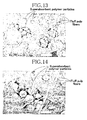
- Fig. 18 of the accompanying drawings exemplarily illustrates a process of the prior art used to make water-absorbent cores.
- a second web 524 formed of a continuous tissue paper is fed from the upstream side in a machine direction MD to a peripheral surface 551a of a suction roll 551.
- the peripheral surface 551a is subjected to a suction effect 556 directed towards a center of the suction roll 551.
- the second web 524 is transported in a feeding region 552 for water-absorbent materials and sucked into concave portions 553 formed in the peripheral surface 551a of the roll 551 under the suction effect 556.
- fluff pulp fibers 521 and superabsorbent polymer particles 522 are accumulated within the respective concave portions 553 also under the suction effect 556 to form aggregates 560 of the water-absorbent materials 560.
- the aggregates 560 having left the feeding region 552 are sandwiched between a first web 523 formed of a continuous tissue paper fed from above and the second web 524 on which the aggregates 560 are placed to form first composite web 561.
- This first composite web 561 is transported in the machine direction MD and compressed by a pair of press rolls 550 into a second composite web 562 having a desired thickness. This thickness can be adjusted by changing a nip of these press rolls 550.
- the second composite web 562 having passed by the press rolls 550 is cut between each pair of the adjacent aggregates 560 to obtain individual water-absorbent cores 513.
- the core for a disposable diaper according to the invention disclosed in US Patent No. 3,938,522 B contains fluff pulp fibers wherein fluff pulp fibers are transported in the form of a web in the machine direction and once pressed by calendar rolls, then water sprayed and compressed again by calendar rolls.
- JP 2512415 B2 provides an absorbent structure in the form of an air-jet papermaking processed and dried mixture comprising hydrophilic fibers and discrete hydro gel particles of a water-insoluble crosslinked polymer.
- This absorbent structure has a density in a range of about 0.15 to about 1g/cm 3 , a moisture content less than about 10% by mass and a Gurley stiffness less than 2g and is flexible and substantially in a non-bonded state.
- the aggregate is preferably compressed to become as thin as possible to assure that this aggregate may not be bulky and may create a comfortable feeling to the wearer when the bodily fluid absorbent disposable article including this aggregate is put on the wearer's body.
- the aggregate is compressed to a desired thickness by using the method of the prior art, in consideration of a recovery of a thickness after compression, it is necessary to compress the aggregate into a further smaller thickness than a thickness actually required for the finished aggregate.
- the aggregate containing superabsorbent polymer particles such surplus compression may collapse a proper shape of each of the super absorbent polymer particles and cause polymer components having a low crosslink density to be exposed.
- the superabsorbent polymer particles having absorbed water may easily form a gel block.
- the aggregate formed with the gel block in this manner will prevent the superabsorbent polymer particles confined within this gel block from coming in contact with bodily fluids and thereby preventing the aggregate from fulfilling its function as the absorber.
- the amount of bodily fluids of the core including this aggregate may be noticeably decreased and/or the absorption rate for bodily fluids of the core may be noticeably deteriorated.
- An object of the present invention is to provide a method for thinning an aggregate of water-absorbent materials including hydrophilic fibers and superabsorbent polymer particles and to provide a sufficiently thin aggregate of water-absorbent materials obtained by this method.
- the present invention includes a first aspect relating to a method for thinning the aggregate of water-absorbent materials and a second aspect relating to a sufficiently thin aggregate of water-absorbent materials obtained by the method according to the first aspect.
- a method for thinning the aggregate of water-absorbent materials including hydrophilic fibers and superabsorbent polymer particles in a thickness direction of the aggregate.
- the first aspect of the present invention includes a step of ejecting steam streams at a temperature corresponding to water's boiling point or higher against the aggregate while this aggregate is compressed in the thickness direction to thin the aggregate.
- the aggregate is sandwiched and compressed by a pair of air-permeable supporting means opposed to each other in the thickness direction of the aggregate while the steam streams are ejected against the aggregate in the thickness direction through one of the pair of air-permeable supporting means.
- the steam streams are one of moist steam streams, saturated steam streams and dry steam streams.
- the steam streams are high pressure steam streams at a steam pressure in a range of 0.1 to 2.0MPa.
- the steam is sucked under vacuum suction effect after the steam streams has been ejected against the aggregate and has passed through the aggregate.
- the pair of air-permeable supporting means respectively include segments adapted to sandwich the aggregate and to run in one of a horizontal direction, a vertical direction and a tilted direction between these horizontal and vertical directions.
- each of the pair of air-permeable supporting means is an endless belt.
- the aggregate is previously thinned by mechanically compressing the aggregate in the thickness direction and thereafter the steam streams are ejected against the aggregate kept under compression.
- the aggregate is mechanically compressed using at least a pair of pressure rolls for previously thinning the aggregate.
- At least one of a side facing one of the pair of air-permeable supporting means and a side facing the other of the pair of air-permeable supporting means of the aggregate is covered with one of an air-permeable sheet and an air-permeable and liquid-pervious sheet and thereafter the aggregate is sandwiched between the pair of air-permeable supporting means.
- one of a side of the aggregate facing the one of the pair of air-permeable supporting means and the other side of the aggregate facing the other of the pair of air-permeable supporting means is covered with one of an air-permeable sheet, an air-permeable and liquid-pervious sheet and a non-air-permeable sheet.
- the aggregate in the step of separating the aggregate, after having been subjected to ejection of the steam streams, from the one of the pair of air-permeable supporting means and the other of the pair of air-permeable supporting means, the aggregate is subjected to the vacuum suction effect through any one of the pair of air-permeable supporting means.
- the aggregate includes the hydrophilic fibers in a range of 98 to 10% by mass and the superabsorbent polymer particles in a range of 2 to 90% by mass.
- the hydrophilic fibers may be selected from a group including fluff pulp fibers, cotton fibers, rayon fibers, acetate fibers and thermoplastic synthetic fibers modified to become hydrophilic.
- the superabsorbent polymer particles may be selected from particles of polyacrylic acid, polyacrylate, starch-acrylonitrile graft copolymer, polyvinyl alcohol, polyvinyl ether, polyacrylamide, carboxymethyl cellulose or natural polysaccharide.
- one of the air-permeable sheet and the air-permeable and liquid-pervious sheet is one of a tissue paper and a nonwoven fabric.
- a sufficiently thin aggregate of water-absorbent materials made by the method according to the first aspect of the present invention.
- the hydrophilic fibers in the aggregate can be easily deformed under the effect of steam streams ejected thereagainst without requiring a significantly high mechanical compression and the aggregate once deformed under the effect of steam is slow to restore its initial shape.
- the aggregate including such hydrophilic fibers can be also quickly thinned and is slow to restore its initial thickness.
- the aggregate may be compressed in this manner to prevent the superabsorbent polymer particles included in the aggregate from losing the shape thereof.
- the superabsorbent polymer particles would not partially or wholly collapse even when the superabsorbent polymer particles absorb water and such an aggregate of water-absorbent material may be well resistant to formation of gel block. Thus the problems due to formation of gel block may be prevented from occurring.
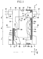
- Fig. 1 is a partially cutaway plan view of an open-type disposable diaper 1 using a thin water-absorbent material aggregate according to one embodiment of the present invention as a bodily fluid absorbent core 13.
- the diaper 1 has a front-back direction A and transverse direction B extending orthogonally to each other and includes a rectangular chassis 2 which is relatively long in the front-back direction A, a pair of front wings 3 attached to a front portion of the chassis 2 to extend in the transverse direction B and a pair of rear wings 4 attached to a rear portion of the chassis 2 to extend in the transverse direction B.
- a crotch region 6 is defined between the front wings 3 and the rear wings 4
- a front waist region 7 is defined in front of the crotch region 6
- a rear waist region 8 is defined behind the crotch region 6.
- the chassis 2 includes a liquid-pervious topsheet 11, a liquid-impervious backsheet 12 and a bodily fluid absorbent core 13 sandwiched between these top- and backsheets 11, 12 wherein the backsheet 12 is covered with an outer sheet 14 made of nonwoven fabric providing comfortable texture.
- the topsheet 11 and the backsheet 12 extend outward beyond a peripheral edge 51 of the core 13 and are put flat and bonded together with hot melt adhesive 41a outside the peripheral edge 51.
- Portions of these topsheet 11, backsheet 12 and outer sheet 14 extending outward beyond the peripheral edge 51 of the core 13 respectively define opposite side edges 18 and front and rear ends 61, 62.
- the side edges 18 are respectively provided with leak barriers 31 formed of pieces of sheet which are relatively long in the front-back direction A.
- Each of the leak barriers 31 has a basal edge 33 bonded to the associated side edge 18 with hot melt adhesive 32a, a front end 34 bonded to the front end 61 with hot melt adhesive 32b, a rear end 36 bonded to the rear end 62 with hot melt adhesive 32c and a free edge 37 opposed to the associated basal edge 33 and disposed inwardly as viewed in the transverse direction of the chassis 2 to overlap the topsheet 11 and adapted to be spaced upward from the topsheet 11.
- the free edge 37 is formed with a sleeve 38 containing an elastic member 39 bonded under tension to an inner surface thereof with hot melt adhesive (not shown).
- the side edges 18 of the chassis 2 are respectively further provided with leg elastic members 41 sandwiched between the outer sheet 14 and the respective basal edges 33 of the leak barriers 31 to extend in the front-back direction A and attached under tension to the outer sheet 14 with hot melt adhesive 41a.
- the front end 61 of the chassis 2 is provided with a front waist region elastic member 42 sandwiched between the topsheet 11 and the backsheet 12 to extend in the transverse direction B and attached under tension to at least one of these top- and backsheets 11, 12 with hot melt adhesive (not shown).
- the rear end 62 of the chassis 2 is provided with a rear waist region elastic member 43 sandwiched between the topsheet 11 and the backsheet 12 to extend in the transverse direction B and attached under tension to at least one of these top- and backsheets 11, 12 with hot melt adhesive (not shown).
- the chassis 2 constructed in this manner is provided along the side edges 18 in the front waist region 7 with the front wings 3 respectively extending outward in the transverse direction B and along the side edges 18 in the rear waist region 8 with the rear wings 4 respectively extending outward in the transverse direction B.
- the rear wings 4 are respectively provided with tape fasteners 46. These tape fasteners 46 are adapted to be unfolded in the transverse direction B as indicated by imaginary lines and to be temporarily fixed to the outer surface of the chassis 2 or the outer surfaces of the respective front wings 3 with pressure-sensitive adhesive 47 applied to inner surfaces of the respective tape fasteners 46.
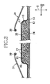
- Fig. 2 is a sectional view taken along the line II-II in Fig. 1 wherein a thickness direction of the core 13 is indicated by the double-headed arrow C.
- the line II-II corresponds to the center line M-M bisecting a dimension of the chassis 2 in the front-back direction A.
- the core 13 includes a compressed aggregate 20 which has been formed by compressing water-absorbent materials including hydrophilic fibers 21 and superabsorbent discrete polymer particles 22 until the aggregate 20 becomes sufficiently thin, air-permeable and liquid-pervious upper sheet 23 and air-permeable lower sheet 24 covering upper and lower surfaces of the compressed aggregate 20, respectively.
- Structural proportion of the hydrophilic fibers 21 in the compressed aggregate 20 is in a range of 98 to 10% by mass and, as the hydrophilic fiber 21, for example, natural fiber such as fluff pulp fibers or cotton fibers, semisynthetic fibers such as rayon fibers, or thermoplastic synthetic fibers modified to become hydrophilic each having a fiber length in a range of 2 to 80mm may be used. It should be understood here that 15% or less by mass of the compressed aggregate 20 may be replaced by hydrophobic thermoplastic synthetic fibers not modified to become hydrophilic and having a fiber length in a range of 20 to 80mm. Such thermoplastic synthetic fibers may sometimes promote bodily fluids to spread in the compressed aggregate 20.
- the proportion of the superabsorbent polymer particles 22 in the structure of the compressed aggregate 20 is in a range of 2 to 90% by mass and, as the superabsorbent polymer particles 22, polymer particles commonly used in the related technical field such as particles of polyacrylic acid, polyacrylate, starch-acrylonitrile graft copolymer, polyvinyl alcohol, polyvinyl ether, polyacrylamide, carboxymethyl cellulose or natural polysaccharide can be used.
- particles 22 of these polymers may have spherical or fibrous shape and may sometimes be amorphous
- the present invention is not limited to any particular shape of the polymer particles 22 and the polymer particles 22 of any shape can be used as the superabsorbent polymer particles 22 so far as the polymer particles 22 can be mixed with the hydrophilic fibers 21.
- the superabsorbent polymer particles 22 according to the present invention may be defined as "superabsorbent polymer particles having the shape adapted to be mixed with the hydrophilic fibers 21".
- the expression "the superabsorbent polymer particles 22 can be mixed with the hydrophilic fibers 21" used herein includes, in addition to the above-mentioned case in which the superabsorbent polymer particles 22 can be uniformly mixed with the hydrophilic fibers 21, the case in which the superabsorbent polymer particles 22 are eccentrically-located in the compressed aggregate 20 of the water-absorbent materials, in other words, in any region of the core 13 of Fig. 2 , in the front-back direction A, the transverse direction B or the thickness direction C.
- the upper sheet 23 is used to face the lower surface of the topsheet 11 and the lower sheet 24 is used to face the upper surface of the backsheet 12.
- a tissue paper having a basis mass in a range of 10 to 30g/m 2 or a nonwoven fabric having a basis mass in a range of 5 to 40g/m 2 may be used.
- air-permeable sheet materials or, in addition, liquid-pervious sheet materials both adapted to facilitate permeation of water vapor as will be described later may be preferably used.
- the lower sheet 24 also to be air-permeable and liquid-pervious and sometimes required to be less liquid-pervious than the upper sheet or liquid-impervious so that movement of bodily fluids from the compressed aggregate 20 to the backsheet 12 may be restricted.
- the upper sheet 23 and the lower sheet 24 extend outward beyond the peripheral edge of the compressed aggregate 20 and put flat and bonded together outside the peripheral edge and thereby serve to maintain the initial shape of the compressed aggregate 20.
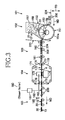
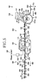
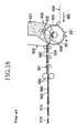
- Fig. 3 is a diagram exemplarily illustrating a process according to the present invention for making the compressed aggregate 20 and the core 13 including this aggregate 20.
- the machine direction MD in which various kinds of material are transported and a thickness direction TD corresponding to the thickness direction C of the core 13 and extending orthogonally to the machine direction MD are indicated by arrows.
- a direction orthogonal to both the machine direction MD and the thickness direction TD is a cross direction CD (not shown).
- the process illustrated in Fig. 3 includes first through fifth steps 101 to 105.
- an air-permeable or an air-permeable and liquid-pervious second sheet web 224 corresponding to a continuous lower sheet 24 is continuously fed in the machine direction MD by delivery rolls 200 rotating in the machine direction MD.
- the second step 102 includes a suction drum 151 rotating in the machine direction MD and a hooded water-absorbent material feeding region 152 to cover the suction drum 151.
- a suction drum 151 rotating in the machine direction MD and a hooded water-absorbent material feeding region 152 to cover the suction drum 151.
- On a peripheral surface 151a of the suction drum 151 is formed a plurality of depressions 153 each having a shape substantially corresponding to a planar shape of the core 13 and arranged at a predetermined pitch in a peripheral direction.
- the depression 153 is subjected to vacuum suction effect 156 as this depression 153 reaches the feeding region 152.
- the feeding region 152 is the region in which the water-absorbent materials according to the present invention is delivered to the suction drum 151 and includes a fluff pulp fiber feeding region 157 adapted to feed the fluff pulp fibers 21a as the hydrophilic fibers 21 constituting the water-absorbent materials and a superabsorbent polymer particle feeding region 158 adapted to feed the superabsorbent polymer particles 22 constituting the water-absorbent materials.
- the feeding region 152 is adapted to feed the fluff pulp fibers 21a and the superabsorbent polymer particles 22 into the depression 153 reaching the feeding region 152 so that the fluff pulp fibers 21a and the superabsorbent polymer particles 22 may be mixed or laminated with each other.
- the second sheet web 224 coming from the first step 101 is received by the peripheral surface 151a of the suction drum 151, then reaches the feeding region 152 and is successively deformed in accordance with the shapes of the respective depressions 153 under the vacuum suction effect 156. In this way, the second sheet web 224 covers the surfaces of the respective depressions 153.
- the fluff pulp fibers 21a and the superabsorbent polymer particles 22 are delivered into the depressions 153 after these depressions 153 have been covered with the second sheet web 224 in this manner. While the hooded feeding region 152 is substantially implemented in the form of a closed structure, a clearance is left between the feeding region 152 and the peripheral surface 151a of the suction drum 151 so that the second sheet web 224 and a water-absorbent material aggregate 160 as will be described later may smoothly run forward.
- the second sheet web 224 leaving the peripheral surface 151a of the suction drum 151 is transported forward by delivery rolls 200 in the machine direction MD.
- a plurality of the aggregates 160 of water-absorbent material each deformed in accordance with the planar shape of the depression 153 and in a still-not-compressed state are arranged intermittently in the machine direction MD.
- Each of the aggregates 160 includes the fluff pulp fibers 21a and the superabsorbent polymer particles 22 delivered into the depression 153 and accumulated therein in the second step 102.
- an air-permeable or, in addition, liquid-pervious first sheet web 223 comprising continuously arranged upper sheets 23 is continuously fed from above as viewed in the diagram and cooperates with the second sheet web 224 to sandwich the aggregates 130 therebetween.
- these first and second sheet webs 223, 224 cooperate with the aggregates 160 arranged intermittently in the machine direction MD to form a first composite web 161.
- the fourth step 104 in Fig. 3 includes air-permeable first and second mesh conveyor belts 171, 172 vertically paired as viewed in Fig 3 , a steam ejection unit 173 and a steam suction unit 174.
- the vertically paired first and second mesh conveyor belts 171, 172 are air-permeable support means for the aggregates 160 and for the first composite web 161 serving to transport the first composite web 161 including the aggregates 160 in the machine direction MD under compressive effect in the thickness direction of the aggregates 160, i.e., in the thickness direction TD in Fig. 3 .
- the first and second mesh conveyor belts 171, 172 run in parallel to each other, for example, at a velocity in a range of 5 to 500m/min in the machine direction MD.
- a nip between an upper roll 176 and a lower roll 177 on the upstream side, both rotating in the machine direction MD, as well as a nip between an upper roll 178 and a lower roll 179 on the downstream side, both rotating in the machine direction MD, may be adjusted to adjust a clearance d between the parallel running segments 175 in the thickness direction TD.
- the aggregates 160 and the first composite web 161 can be compressed to a desired thickness by these first and second mesh conveyor belts 171, 172 of which the parallel running segments 175 are adjustably spaced from each other in the thickness direction TD.
- the parallel running segments 175 cooperate with the steam ejection unit 173 and the steam suction unit 174 opposed to each other about the parallel running segments 175 of the first and second mesh conveyor belts 171, 172.
- the steam ejection unit 173 includes a plurality of nozzles (not shown) each having a diameter, for example, in a range of 0.1 to 2mm arranged in the cross direction CD (not shown) extending orthogonally to the machine direction MD and to the thickness direction TD at a pitch preferably in a range of 0.5 to 10mm, more preferably in a range of 0.5 to 5mm and most preferably in a range of 0.5 to 3mm to extend across the first composite web 161.
- the respective nozzles are supplied via a piping 182 with steam at a temperature corresponding to water's boiling point or higher generated within a steam boiler 180 and regulated by a pressure-regulating valve to a steam pressure, for example, in a range of 0.1 to 2.0MPa.
- Such high pressure steam streams(not shown) are ejected from the respective nozzles against the first composite web 161 compressed by the first and second mesh conveyor belts 171, 172 through the first mesh conveyor belt 171.
- Ejection quantity of steam streams against the aggregates 160 contained in the first composite web 161 is regulated depending on the running velocity of the first and second mesh conveyor belts 171, 172. Assuming that the first and second mesh conveyor belts 171, 172 run at a velocity in a range of 5 to 500m/min, steam streams in a range of 1.23kg/m 2 to 0.03kg/m 2 per unit area of the aggregates facing the first mesh conveyor belt 171 are preferably ejected against the aggregates 160 through the first sheet web 223.
- At least one of the first and second mesh conveyor belts 171, 172 may be made of material having a sufficient flexibility to be easily deformed in the thickness direction TD to prevent the first composite web 161 from being locally compressed by these first and second mesh conveyor belts 171, 172.
- metallic wire mesh belts formed of, for example, stainless alloy or bronze or plastic mesh conveyor belts formed, for example, of polyester fiber or aramid fiber may be used. It is also possible to use a metallic belt formed of a perforate metal plate.
- the plastic mesh conveyor belts may preferably be used.
- the mesh belts made of polyphenylene sulfide resin may be preferably used.
- Plain woven mesh belts of 10 to 75 meshes are flexible and is one example of a particularly preferable mesh belt which may be used for the first mesh conveyor belt 171 and for the second mesh conveyor belt 172.
- the steam ejection unit 173 and the piping 182 may be preferably provided with appropriate heat-retention means and draining mechanism.
- Such countermeasures may prevent apprehension that drainage generated within the steam ejection unit 173 or the other units might be ejected from the nozzles and make the first composite web 16 have an excessively wetted state and/or damage the first sheet web 223 when the latter is formed of a tissue paper.
- the steam streams may be ejected against the first composite web 161 in the form of dry steam containing no moisture, saturated steam or wet steam containing moisture. Wet steam or saturated steam can easily make the hydrophilic fibers 21 into a wet state and thereby easily deform the hydrophilic fibers 21.
- Dry steam can gasify the moisture contained in the fluff pulp fibers 21a, if the hydrophilic fibers 21 are fluff pulp fibers 21a and the moisture gasified in this manner facilitates the hydrophilic fibers 21 to be deformed.
- the hydrophilic fibers 21 comprising thermoplastic synthetic fibers
- heat of the dry steam facilitates the thermoplastic synthetic fibers to be deformed.
- the steam ejection unit 173 provided with the heating mechanism, the steam streams can be ejected in the form of overheated steam.
- the steam suction unit 174 is preferably provided with the piping by which the sucked high pressure steam may be guided to an exhaust blower (not shown) after the high pressure steam has passed through a steam-water separator.
- the present invention may be implemented in a manner that the steam ejection unit 173 and the steam suction unit 174 in the fourth step 104 may be positionally interchanged, i.e., the steam ejection unit 173 may lie on the downside of the steam suction unit 174. If it is unnecessary, in the fourth step 104, to collect the high pressure steam having passed through the first composite web 161, the present invention may be implemented without setting up the steam suction unit 174.
- the second composite web 162 having left behind the first and second mesh conveyor belts 171, 172 is received by the deliver rolls 200 to run in the machine direction MD and, in the course of running, cut along a middle line between each pair of the adjacent aggregates 160 into the individual core 13.
- the aggregate 160 obtained in this manner is an aggregate 20 (See Fig. 2 ) compressed by the first and second mesh conveyor belts 171, 172 and the steam wherein the first and second sheet webs 223, 224 define the upper and lower sheets 23, 24 of the core 13.
- the aggregate 160 of water-absorbent material including a mixture of the hydrophilic fibers 21 and the superabsorbent polymer particles 22 has been compressed between the first mesh conveyor belt 171 and the second mesh conveyor belt 172 under ejection of higher pressure steam streams. Consequently, the hydrophilic fibers 21, for example, the fluff pulp fibers 21a are quickly deformed in a heated and humidified state or a simply heated state and lose any repulsive power against the compressive force of the first and second mesh conveyor belts 171, 172. As a result, the fluff pulp fibers 21a may maintain a shape which is substantially the same as the shape immediately after compression.
- Moisture contained in the steam facilitates each pair of the adjacent hydrophilic fibers 21 to get closer to each other and an interaction between each pair of closely adjacent hydrophilic fibers facilitates the respective hydrophilic fibers to maintain their respective shapes immediately after having been compressed.
- the high pressure steam streams used by the present invention passes through the first composite web 161 more smoothly than sprayed water and therefore the aggregate 160 can be quickly brought to a heated and a humidified state fully in the thickness direction of the aggregate 160.
- the clearance d between the first and second mesh conveyor belts 171, 172 may be set to a value required for the second composite web 162 to obtain the second composite web 162 having a desired thickness without setting the clearance d to an excessively small value.
- a ratio of the second composite web 162 versus the clearance d is a value indicating a recovery rate r of the first composite web 161 after compression and this recovery rate r represents a degree of the effect of the high pressure steam used in the fourth step 104 for compression of the first composite web 16.
- the recovery rate r which is approximate to 1 means that the thickness of the second composite web 162 is substantially equal to the clearance d. According to the present invention using the fourth step 104, the recovery rate r is often approximately 1.
- the recovery rate r often has a value largely surpassing 1.
- both the compressive effect of the steam and the compressive effect of the first and second mesh conveyor belts 171, 172 would not be locally concentrated even if the aggregate 160 of water-absorbent materials has regions locally thicker than the remaining regions.
- the aggregate 160 has a region in which the superabsorbent polymer particles 22 are eccentrically located and the thickness of the aggregate 160 is relatively thick due to the presence of the eccentrically located superabsorbent polymer particles 22, if the first composite web 161 including such aggregate 160 of water-absorbent materials is compressed by the compression roll pair as has been the case in the prior art, the compressive force of the compression roll pair might be concentrated on such thicker region due the presence of the super absorbent polymer particles 22, causing the superabsorbent polymer particles 22 in such region to partially or wholly collapse and/or putting the superabsorbent polymer particles 22 and the hydrophilic fiber 21 in undesirably close contact to one another and/or putting the hydrophilic fibers 21 themselves in excessively close contact with one another.
- the superabsorbent polymer particles 22 have spherical shapes, collapse thereof may lead to exposure of polymer components within the particles which have low crosslink density and thereby the superabsorbent polymer particles having absorbed water may readily form a gel block. As a consequence, there is substantially no chance that the superabsorbent polymer particles 22 which are included within the gel block come into contact with bodily fluids and cannot function as the water-absorbent materials. In addition, formation of the gel block transforms the superabsorbent polymer particles 22 from those of small diameter to those of larger diameter. As a result, formation of the gel block deteriorates the primary water absorbing ability and/or the desired flexibility of the aggregate 160.
- the collapse of the superabsorbent polymer particles 22 in the bodily fluid absorbent core 13 should be preferably restricted.
- a phenomenon that the superabsorbent polymer particles 22 come in close contact with the hydrophilic fibers 21, and surfaces of the respective particles 22 are covered with the fibers 21 also should be preferably restricted because the fibers 21 covering the surfaces of the particles 22 in this manner prevent the particles 22 from coming in contact with bodily fluids and make it difficult for the particles 22 to absorb water quickly and eventually the super absorbent polymer particles 22 in the core material 13 may not function quickly.
- close contact between each pair of the adjacent hydrophilic fibers 21 also should be preferably restricted because such close contact delays permeation of bodily fluids through interstices of the fibers and deteriorates the water absorption rate of the aggregate 160.
- the process of Fig. 3 according to the present invention may be partially modified.
- the second sheet web 224 and the first and second composite webs 161, 162 run horizontally in the machine direction MD in the first step 101 and the third, fourth and fifth steps 103, 104, 105 in the illustrated embodiment, it is possible to arrange it so that the paths for the second sheet web 224 and the first and second composite webs 161, 162 may be modified to extend in vertical or tilted directions. Such modifications may be appropriately selected depending on various factors such as a plant space available for the process of Fig. 3 .
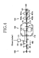
- Fig. 4 is a diagram similar to Fig. 3 except for the third step 103, illustrating another embodiment of the present invention.
- the third step 103 in Fig. 4 includes a first compression roll pair 401a, 401b and a second compression roll pair 402a, 402b for the purpose of moderately compressing the first composite web 161 by mechanical means.
- a roll nip e 1 of the first compression roll pair 401a, 401b and a roll nip e 2 of the second compression roll pair 402a, 402b are set to compress the first composite web 161 to a degree of thickness with which the first composite web 161 can smoothly make its way into the respective nips of the first and second mesh conveyor belts 171, 172.
- the shape distortion or other abnormal situation which would otherwise occur in the aggregate 160 when the first composite web 161 makes its way into the nips of the first and second mesh conveyor belts 171, 172 after having been compressed by the first compression roll pairs 401a, 401b and the second compression roll pairs 402a, 402b is effectively prevented and the sufficiently thin core 13 can be produced.
- the third step 103 of Fig. 4 may be variously modified.
- any one of the first compression roll pair 401a, 401b and the second compression roll pair 402a, 402b may be eliminated.
- the third step 103 may include one or more additional compression roll pair(s).
- Fig. 5 is a diagram illustrating still another embodiment of the present invention.
- the air-permeable first sheet web 223 is continuously fed in the machine direction MD.
- the first composite web 161 includes the first sheet web 223 and the aggregates 160 of water-absorbent material intermittently placed on the first sheet web 223 and does not include the second sheet web 224 in Fig. 3 .
- such first composite web 161 is introduced between the first and second mesh conveyor belts 171, 172 opposed to each other with the clearance d and simultaneously steam streams are ejected from the steam ejection unit 173 to the aggregates 160.
- the fourth step 104 includes a second suction box 192 provided below the first composite web 161 and the second mesh conveyor belt 172 in the vicinity of the upper roll 178 on a downstream side at which the first mesh conveyor belt 171 running in the machine direction MD is separated from the first composite web 161.
- Vacuum suction force exerted from the second suction box 192 upon the aggregates 160 through the second mesh conveyor belt 172 functions to prevent fibers of the aggregates 160 which have been covered with the first mesh conveyor belt 171 from fluffing and/or flying apart.
- the surfaces of the respective aggregates 161 having faced the first mesh conveyor belt 171 are now covered with the second sheet web 224 in the fifth step 105 to form the second composite web 162.
- the second composite web 162 is intermittently cut by the cutter 185 into the individual cores 13 and the aggregates 160 are divided into the individual compressed aggregates 20.
- the process of Fig. 5 may use the same hydrophilic fibers 21, the superabsorbent polymer particles 22 and the first sheet web 223 as used in the process of Fig. 3 . While it is also possible to use the same second sheet web 224 as that used in the process of Fig. 3 , not only the air-permeable sheet web but also an air-nonpermeable sheet web or an air-and-liquid-nonpermeable sheet may be used because no steam ejections through the second sheet web 224 occurs in the process of Fig. 5 .
- Fig. 6 is a diagram similar to Fig. 5 , illustrating yet another embodiment of the present invention.
- the process of Fig. 6 also includes first through fifth steps 101 through 105.
- the first step 101 includes an air-permeable endless belt 110 adapted to run in the machine direction MD, the suction drum 151 and the hooded water-absorbent material feeding region 152 provided above the air-permeable endless belt 110. While both the drum 151 and the feeding region 152 are the same as those exemplarily illustrated in Fig. 5 , the second sheet web 224 is not delivered to the drum 151.
- the drum 151 is formed on its peripheral surface with the depressions 153 at a predetermined pitch in the circumferential direction.
- the third suction box 113 is located via the belt 110 and the aggregates 160 having been discharged are received by the belt 110 under the suction effect of the third suction box 113.
- an appropriate mechanical effect may be used to retract the bottom of the depression 153 in the radial direction and to discharge the aggregates 160.
- the aggregates 160 are placed on the belt 110 and run in the machine direction MD.
- the belt 110 runs, for example, at a rate of 5 to 500m/min toward the third step 103.
- the third step 103 in the process of Fig. 6 includes, in addition to the belt 110, the first mesh conveyor belt 171, the steam ejection unit 173, the steam suction unit 174 and the second suction box 192, the same as those used in Fig. 3 or Fig. 5 .
- a clearance in the vertical direction between the upper roll of upstream 176 and the lower roll of upstream 177 and a clearance in the vertical direction between the upper roll of downstream 178 and the lower roll of downstream 179 may be adjusted.
- the first mesh conveyor belt 171 is shorter than the belt 110 and separated from the surface of the aggregates 160 in the vicinity of the downstream upper roll 178 so that the aggregates 160 are subjected to the suction effect by the second suction box 192 immediately below the downstream upper roll 178 in the same manner as in the fourth step 104 in the process of Fig. 5 .
- the aggregates 160 separated from the first mesh conveyor belt 171 still lie on the belt 110 and move to the fourth step 104.
- air-permeable first web 223 is fed from above as viewed in Fig. 6 onto the upper surface of the aggregates 160 on the belt 110 facing the first mesh conveyor belt 171 as viewed in Fig. 6 to cooperate with these aggregates 160 to form the first composite web 161.
- the first composite web 161 is introduced between the belt 110 and the air-permeable second endless belt 112 running in the machine direction MD.
- a clearance between the belt 110 and the second endless belt 112 is set substantially equal to the clearance between the belt 110 and the first mesh conveyor belt 171.
- a fourth suction box 194 is adapted to exert a vacuum suction effect on the first composite web 161 through the second endless belt 112.
- the downstream lower roll 179 is used to separate the belt 110 from the aggregates 160 of the first composite web 161 under the vacuum suction effect. Exerting the vacuum suction effect on the first composite web 161, the second sheet web 224 is fed from below as viewed in Fig.
- the second composite web 162 comprising the aggregates 160, and the first and second sheet webs 223, 224.
- the second composite web 162 running in the machine direction MD is cut between each pair of the adjacent aggregates 160, 160 to obtain the individual cores 13. Thereupon, the aggregates 160 are divided into the individual compressed aggregates 20.
- the present invention can be implemented without the steam suction.
- the steam suction unit 174 may sometimes be eliminated.
- the core 13 containing such compressed aggregate 20 may be used as a thin compressed aggregate or core in the bodily-fluid absorbent disposable article such as the disposable diaper 1 exemplarily illustrated in Fig. 1 and other articles such as a menstruation napkin or a urine absorbent pad.
- the present invention has been described above on the basis of the processes exemplarily illustrated in Fig. 3 through Fig. 6 adapted to produce the thin compressed aggregates 20 in continuous fashion from the aggregate 160, the present invention may be targeted at the elemental aggregate comprising an elemental aggregate 160 or such elemental aggregate 160 wrapped with the air-permeable sheet.
- fluff pulp fibers were used with a basis mass of 240g/m 2 as the hydrophilic fibers, SA60S available from Sumitomo Seika Chemicals Company Limited including spherical particles and aggregates of spherical particles were used with a basis mass of 240g/m 2 as the superabsorbent polymer particles, a through-air nonwoven fabric made of core-in-sheath type conjugate fiber having a basis mass of 25g/m 2 comprising polypropylene core and polypropylene sheath, and having a fineness of 2 dtex and a fiber length of 51mm was used as the first sheet web and tissue paper having a basis mass of 18g/m 2 was used as the second sheet web to obtain the first composite web including the aggregate of water-absorbent material having a thickness of 0.18mm and dimensions in the machine direction and the cross direction of 300mm and 200mm, respectively.
- the first composite web was transported at a velocity of 5m/min to the fourth step and guided into the clearance between a pair of flexible mesh conveyor belts adjusted as will be indicated later.
- Plain woven mesh belt of 30 meshes made of polyphenylene sulfide resin was used as the respective mesh conveyor belts.
- High pressure steam streams of 0. 7 MPa was ejected from nozzles of the steam ejection unit, each having a diameter of 0.5mm, arranged at a pitch of 2mm in the cross direction to the first composite web to obtain the second composite web.
- the second composite web was cut to obtain the individual cores according to Examples 1 through 3 each including the compressed aggregate of water-absorbent materials sandwiched between the through-air nonwoven fabric and a tissue paper.
- the respective clearances between the pair of mesh conveyor belts in Examples 1 through 3 were adjusted to values as indicated below.
- a through-air nonwoven fabric facilitating the water-absorbent materials to be peeled off from the aggregate was used as the upper sheet and thereby a potential influence of such peeling off upon the surface condition of the aggregate was negligibly alleviated during observation of the surface condition of the aggregate.
- the sample piece was placed on a horizontal plane so that the second sheet web defines the lower surface and a tip of an auto-burette was set 20mm above an upper surface of the sample piece at its central region.
- 10cc of artificial urine was dropped from the tip of the auto-burette at a rate of 120cc/min.
- a short absorption time means that the absorption rate is high.
- a range of the artificial urine spreading on the upper surface of the sample piece in the machine direction and the cross direction was also measured.
- the result of the measurement was recorded in TABLE 1.
- the artificial urine was prepared by mixing or dissolving ingredients as mentioned below in 10 liter of ion-exchanged water: Urea: 200g Sodium chloride: 80g Magnesium sulfate: 8g Calcium chloride: 3g Pigment Blue No. 1: 1g h.
- the core was cut into a size of 100mm x 100mm and the through-air nonwoven fabric used as the first sheet web in the process for making the core was peeled off from the aggregate of water-absorbent material to obtain a sample piece for measurement.
- the sample piece was placed on a horizontal reference surface with the lower surface of the core as its downside and values of height from the reference surface to respective regions on the upper surface of the sample piece were measured to obtain variation in the height corresponding to irregularity of the upper surface. Based on a degree of the variation, quality of the surface smoothness in the aggregate of water-absorbent material was evaluated.
- b Quality of the surface smoothness in the aggregate of water-absorbent material
- High-Accuracy Geometry Measuring System (inclusive of High-Accuracy Stage: KS-1100) and High-Speed and High-Accuracy CCD-Laser Displacement Gauge inclusive of Controller: LK-G3000V Set and Sensor Head: LK-G30) manufactured by Keyence Corporation were used.
- Stage conditions were set as following: Range of measurement: 40000 ⁇ m x 40000 ⁇ m Measuring pitch: 20 ⁇ m Running speed: 7500 ⁇ m/sec d.
- Conditions of the measuring head (LK-G3000) were set as following: Measurement mode: Object to be measured Installation mode: Diffuse reflection Filtering: four (4) times in average Sampling period: 200 ⁇ s e.
- the data obtained on the basis of the sample piece (a) was processed by using a configuration analysis software (KS-H1A).
- the data having been processed was transferred to Excel, spreadsheet software of Microsoft, by extracting Z-coordinates each associated with 16 spots on the X- and Y-coordinates, respectively.
- KS-H1A configuration analysis software
- a contour graph was created on the basis of X-, Y- and Z-coordinates.
- histogram processing of all Z-coordinates was carried out utilizing add-in features of this software. f.
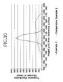
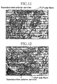
- the data processing method employed by the present invention allows the measurement result to be illustrated in the form of a polygonal line graph wherein, for example, X-coordinates are fixed and Y-coordinates are left variable to indicate values of Z-coordinates varying in association with the respective Y-coordinates. While such a polygonal line graph can be separated by color depending on values of the fixed X-coordinates, the polygonal line graph of Figs. 8 and 9 are illustrated simply by black lines. In Fig. 10 , the height from the reference surface to the upper surface is indicated by abscissa axis and the frequency (the number of times) at which the height was detected is indicated by axis of ordinate.
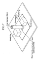
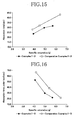
- Fig. 15 is a graphic diagram plotting relationships between the absorption rates and the specific volumes both recorded in Table 1.
- the core which is most preferable in view of the highest absorption rate is the core 13 according to the Example (See Figs. 11 and 12 ) wherein adequate clearance is kept between each pair of the adjacent hydrophilic fibers 21 and between the hydrophilic fibers 21 and the adjacent superabsorbent polymer particles.
- Fig. 16 is a graphic diagram plotting relationships between the absorption times under load and the specific volumes both recorded in TABLE 1. So far as the cores according to the Examples and the Comparative Examples, which were selected as the observation objects, are concerned, the pattern in which the absorption time under load is shortened was observed, i.e., the absorption rate under load is accelerated as the specific volume sizes up. Such pattern was common to the Examples and Comparative Examples.
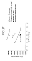
- Fig. 17 is a graphic diagram plotting relationships between the airflow resistance indices and the specific volumes both recorded in TABLE 2.
- the pattern was observed in which the airflow resistance indices of the cores according to the Examples are lower than the airflow resistance indices of the cores according to the Comparative Examples. Such pattern was observed on the cores in a dry state and on the cores in a wet state.
- the cores according to the Examples having relatively low airflow resistance indices are the cores having low vapor flow resistance values and correspondingly high air-and-liquid permeability.
Landscapes
- Engineering & Computer Science (AREA)
- Health & Medical Sciences (AREA)
- Textile Engineering (AREA)
- General Health & Medical Sciences (AREA)
- Life Sciences & Earth Sciences (AREA)
- Materials Engineering (AREA)
- Epidemiology (AREA)
- Biomedical Technology (AREA)
- Heart & Thoracic Surgery (AREA)
- Vascular Medicine (AREA)
- Veterinary Medicine (AREA)
- Animal Behavior & Ethology (AREA)
- Chemical & Material Sciences (AREA)
- Public Health (AREA)
- Manufacturing & Machinery (AREA)
- Mechanical Engineering (AREA)
- Absorbent Articles And Supports Therefor (AREA)
- Nonwoven Fabrics (AREA)
- Solid-Sorbent Or Filter-Aiding Compositions (AREA)
Applications Claiming Priority (2)
| Application Number | Priority Date | Filing Date | Title |
|---|---|---|---|
| JP2009272890A JP5702928B2 (ja) | 2009-11-30 | 2009-11-30 | 吸水性材料の集合体を薄くする方法およびその方法によって得られる厚さの薄い吸水性材料の集合体 |
| PCT/JP2010/070439 WO2011065262A1 (ja) | 2009-11-30 | 2010-11-17 | 吸水性材料の集合体を薄くする方法およびその方法によって得られる厚さの薄い吸水性材料の集合体 |
Publications (3)
| Publication Number | Publication Date |
|---|---|
| EP2508662A1 EP2508662A1 (en) | 2012-10-10 |
| EP2508662A4 EP2508662A4 (en) | 2013-04-24 |
| EP2508662B1 true EP2508662B1 (en) | 2014-09-10 |
Family
ID=44066367
Family Applications (1)
| Application Number | Title | Priority Date | Filing Date |
|---|---|---|---|
| EP10833109.1A Not-in-force EP2508662B1 (en) | 2009-11-30 | 2010-11-17 | Method for reducing thickness of mass of water-absorbing material and thin mass of water-absorbing material obtained by the method |
Country Status (8)
| Country | Link |
|---|---|
| US (1) | US20120231946A1 (enExample) |
| EP (1) | EP2508662B1 (enExample) |
| JP (1) | JP5702928B2 (enExample) |
| KR (1) | KR20120098729A (enExample) |
| CN (1) | CN102630260A (enExample) |
| AU (1) | AU2010323772A1 (enExample) |
| TW (1) | TW201200114A (enExample) |
| WO (1) | WO2011065262A1 (enExample) |
Families Citing this family (18)
| Publication number | Priority date | Publication date | Assignee | Title |
|---|---|---|---|---|
| EP2535698B1 (en) * | 2011-06-17 | 2023-12-06 | The Procter & Gamble Company | Absorbent article having improved absorption properties |
| JP5885954B2 (ja) * | 2011-07-29 | 2016-03-16 | ユニ・チャーム株式会社 | 芯材の製造方法 |
| KR20140143144A (ko) * | 2012-03-05 | 2014-12-15 | 몬트레이드 에스.알.엘. | 필터 로드 성형 기계에 필터 재료를 공급하는 방법 및 장치 |
| ITBO20120106A1 (it) * | 2012-03-05 | 2013-09-06 | Montrade Srl | Metodo e macchina per la produzione di filtri senza carta per articoli da fumo |
| SG11201405418WA (en) * | 2012-03-30 | 2014-11-27 | Unicharm Corp | Absorbent and absorbent article provided therewith |
| JP2014079566A (ja) * | 2012-09-30 | 2014-05-08 | Uni Charm Corp | 吸収性物品 |
| JP6094993B2 (ja) * | 2012-12-27 | 2017-03-15 | 花王株式会社 | 吸収体の製造方法 |
| US10596042B2 (en) | 2013-09-30 | 2020-03-24 | Kimberly-Clark Worldwide, Inc. | Method of forming an absorbent structure |
| US9572729B2 (en) | 2013-09-30 | 2017-02-21 | Kimberly-Clark Worldwide, Inc. | Method of forming an absorbent structure |
| JP7027103B2 (ja) * | 2017-10-03 | 2022-03-01 | 花王株式会社 | 吸収体の製造方法及び吸収体の製造装置 |
| IT201700123038A1 (it) * | 2017-10-30 | 2019-04-30 | Gdm Spa | Apparato e metodo di formatura di una imbottitura assorbente |
| JP6640899B2 (ja) * | 2018-03-09 | 2020-02-05 | 第一衛材株式会社 | 液体吸収シートの製造装置 |
| JP7118752B2 (ja) * | 2018-06-05 | 2022-08-16 | 花王株式会社 | 吸収体の製造方法 |
| CN110485057B (zh) * | 2019-08-06 | 2021-05-18 | 深圳全棉时代科技有限公司 | 一种可入厕棉柔巾的制备方法 |
| JP6819745B2 (ja) * | 2019-09-03 | 2021-01-27 | 王子ホールディングス株式会社 | 吸収性物品の製造方法および製造装置 |
| JP6819744B2 (ja) * | 2019-09-03 | 2021-01-27 | 王子ホールディングス株式会社 | 吸収性物品の製造方法および製造装置 |
| JP7159141B2 (ja) * | 2019-09-26 | 2022-10-24 | 大王製紙株式会社 | 機能性シート及びこれを備えた吸収性物品、並びにこれらの製造方法 |
| CN116942882B (zh) * | 2023-07-27 | 2024-03-26 | 广东美登新材料科技有限公司 | 一种超薄芯体纸尿裤及其制备方法 |
Family Cites Families (13)
| Publication number | Priority date | Publication date | Assignee | Title |
|---|---|---|---|---|
| US3938522A (en) | 1972-06-26 | 1976-02-17 | Johnson & Johnson | Disposable diaper |
| JPS54123293A (en) * | 1978-03-16 | 1979-09-25 | Mitsubishi Rayon Co | Preparation of sheettlike matter on which pulverulent body is laminated and its device |
| DK167952B1 (da) * | 1983-03-10 | 1994-01-10 | Procter & Gamble | Absorbentstruktur, som er en blanding af hydrofile fibre og vanduoploeselig hydrogel i form af saerskilte partikler af tvaerbundet polumert materiale, fremgangsmaade til fremstilling af samme samt engangsble fremstillet heraf |
| AT399308B (de) * | 1993-04-29 | 1995-04-25 | Eternit Werke Hatschek L | Verfahren und anlagen zur herstellung von aus fasern und hydraulischem bindemittel bestehenden produkten |
| US5674587A (en) * | 1994-09-16 | 1997-10-07 | James; William A. | Apparatus for making nonwoven fabrics having raised portions |
| JP3340902B2 (ja) * | 1995-12-28 | 2002-11-05 | 花王株式会社 | 帯状の繊維集合体の製造方法及びその装置 |
| US20030234468A1 (en) * | 1997-01-17 | 2003-12-25 | Krishnakumar Rangachari | Soft, absorbent material for use in absorbent articles and process for making the material |
| US6485667B1 (en) * | 1997-01-17 | 2002-11-26 | Rayonier Products And Financial Services Company | Process for making a soft, strong, absorbent material for use in absorbent articles |
| US6146568A (en) * | 1999-04-12 | 2000-11-14 | Kimberly-Clark Worldwide, Inc. | Method of making an absorbent member |
| AU3074602A (en) * | 2000-12-20 | 2002-07-01 | Kimberly Clark Co | Thin, high capacity absorbent structure and method for producing same |
| DE10218147B4 (de) * | 2002-04-23 | 2005-12-22 | Stockhausen Gmbh | Wasserabsorbierende, die Zersetzung von Körperflüssigkeiten verzögernde Polymerteilchen, deren Herstellung und Verwendung |
| JP4439854B2 (ja) * | 2002-10-08 | 2010-03-24 | 三菱レイヨン・エンジニアリング株式会社 | 加圧蒸気噴出ノズルと同ノズルを用いた不織布の製造方法 |
| DE102008007804A1 (de) * | 2007-06-11 | 2008-12-18 | Fleissner Gmbh | Vorrichtung zur Verfestigung von Fasern und/oder von aus Filamenten gebildeten Vliesen |
-
2009
- 2009-11-30 JP JP2009272890A patent/JP5702928B2/ja not_active Expired - Fee Related
-
2010
- 2010-11-17 KR KR1020127013036A patent/KR20120098729A/ko not_active Ceased
- 2010-11-17 EP EP10833109.1A patent/EP2508662B1/en not_active Not-in-force
- 2010-11-17 CN CN2010800540669A patent/CN102630260A/zh active Pending
- 2010-11-17 US US13/512,660 patent/US20120231946A1/en not_active Abandoned
- 2010-11-17 WO PCT/JP2010/070439 patent/WO2011065262A1/ja not_active Ceased
- 2010-11-17 AU AU2010323772A patent/AU2010323772A1/en not_active Abandoned
- 2010-11-29 TW TW099141220A patent/TW201200114A/zh unknown
Also Published As
| Publication number | Publication date |
|---|---|
| EP2508662A1 (en) | 2012-10-10 |
| TW201200114A (en) | 2012-01-01 |
| US20120231946A1 (en) | 2012-09-13 |
| WO2011065262A1 (ja) | 2011-06-03 |
| AU2010323772A1 (en) | 2012-05-31 |
| EP2508662A4 (en) | 2013-04-24 |
| CN102630260A (zh) | 2012-08-08 |
| KR20120098729A (ko) | 2012-09-05 |
| JP5702928B2 (ja) | 2015-04-15 |
| JP2011117088A (ja) | 2011-06-16 |
Similar Documents
| Publication | Publication Date | Title |
|---|---|---|
| EP2508662B1 (en) | Method for reducing thickness of mass of water-absorbing material and thin mass of water-absorbing material obtained by the method | |
| RU2570496C2 (ru) | Способ изготовления поглощающего элемента | |
| TWI566752B (zh) | Absorbent items | |
| EP2736472B1 (en) | Bodily fluid absorbent matrix and method for manufacturing the same | |
| JP5319262B2 (ja) | 吸収性物品及びその製造方法 | |
| KR101617917B1 (ko) | 흡수체 | |
| JP2010136899A (ja) | 吸収性物品用の吸収体 | |
| CN114173735A (zh) | 包括具有交替的吸收性材料的高密度区域和低密度区域的芯的吸收性物品 | |
| IE70063B1 (en) | Disposable absorbent product | |
| JPH09512730A (ja) | 吸収性構造体の製造方法及びこの方法により製造された吸収性構造体を含む吸収性傷手当用品 | |
| TWI794565B (zh) | 吸收性物品 | |
| WO2008091726A1 (en) | Product to promote fluid flow | |
| JP4786758B2 (ja) | 吸水性材料の集合体を薄くする方法およびその方法によって得られる厚さの薄い吸水性材料の集合体 | |
| CN114555025B (zh) | 吸收制品 | |
| JP7175826B2 (ja) | 吸収性物品 | |
| US8901368B2 (en) | Absorbent core comprising multiple sublayers | |
| CN111148492B (zh) | 吸收体和吸收性物品 | |
| RU2782001C1 (ru) | Впитывающий элемент и способ его изготовления | |
| JP7412978B2 (ja) | 吸収性物品 | |
| RU2442611C1 (ru) | Новый впитывающий внутренний слой | |
| CN112135593B (zh) | 吸收性物品 | |
| WO2025038681A1 (en) | Absorbent article with absorbent core structure having a shaped inner core layer | |
| CN112351761A (zh) | 吸收体及吸收性物品 |
Legal Events
| Date | Code | Title | Description |
|---|---|---|---|
| PUAI | Public reference made under article 153(3) epc to a published international application that has entered the european phase |
Free format text: ORIGINAL CODE: 0009012 |
|
| 17P | Request for examination filed |
Effective date: 20120614 |
|
| AK | Designated contracting states |
Kind code of ref document: A1 Designated state(s): AL AT BE BG CH CY CZ DE DK EE ES FI FR GB GR HR HU IE IS IT LI LT LU LV MC MK MT NL NO PL PT RO RS SE SI SK SM TR |
|
| DAX | Request for extension of the european patent (deleted) | ||
| A4 | Supplementary search report drawn up and despatched |
Effective date: 20130321 |
|
| RIC1 | Information provided on ipc code assigned before grant |
Ipc: D04H 1/42 20120101ALI20130315BHEP Ipc: D04H 1/48 20120101AFI20130315BHEP Ipc: D04H 1/40 20120101ALI20130315BHEP Ipc: A61F 13/15 20060101ALI20130315BHEP Ipc: A61F 13/49 20060101ALI20130315BHEP Ipc: A61F 13/53 20060101ALI20130315BHEP |
|
| GRAP | Despatch of communication of intention to grant a patent |
Free format text: ORIGINAL CODE: EPIDOSNIGR1 |
|
| INTG | Intention to grant announced |
Effective date: 20140429 |
|
| GRAS | Grant fee paid |
Free format text: ORIGINAL CODE: EPIDOSNIGR3 |
|
| GRAA | (expected) grant |
Free format text: ORIGINAL CODE: 0009210 |
|
| AK | Designated contracting states |
Kind code of ref document: B1 Designated state(s): AL AT BE BG CH CY CZ DE DK EE ES FI FR GB GR HR HU IE IS IT LI LT LU LV MC MK MT NL NO PL PT RO RS SE SI SK SM TR |
|
| REG | Reference to a national code |
Ref country code: GB Ref legal event code: FG4D |
|
| REG | Reference to a national code |
Ref country code: CH Ref legal event code: EP |
|
| REG | Reference to a national code |
Ref country code: IE Ref legal event code: FG4D |
|
| REG | Reference to a national code |
Ref country code: AT Ref legal event code: REF Ref document number: 686748 Country of ref document: AT Kind code of ref document: T Effective date: 20141015 |
|
| REG | Reference to a national code |
Ref country code: DE Ref legal event code: R096 Ref document number: 602010018950 Country of ref document: DE Effective date: 20141023 |
|
| PG25 | Lapsed in a contracting state [announced via postgrant information from national office to epo] |
Ref country code: NO Free format text: LAPSE BECAUSE OF FAILURE TO SUBMIT A TRANSLATION OF THE DESCRIPTION OR TO PAY THE FEE WITHIN THE PRESCRIBED TIME-LIMIT Effective date: 20141210 Ref country code: ES Free format text: LAPSE BECAUSE OF FAILURE TO SUBMIT A TRANSLATION OF THE DESCRIPTION OR TO PAY THE FEE WITHIN THE PRESCRIBED TIME-LIMIT Effective date: 20140910 Ref country code: LT Free format text: LAPSE BECAUSE OF FAILURE TO SUBMIT A TRANSLATION OF THE DESCRIPTION OR TO PAY THE FEE WITHIN THE PRESCRIBED TIME-LIMIT Effective date: 20140910 Ref country code: GR Free format text: LAPSE BECAUSE OF FAILURE TO SUBMIT A TRANSLATION OF THE DESCRIPTION OR TO PAY THE FEE WITHIN THE PRESCRIBED TIME-LIMIT Effective date: 20141211 Ref country code: FI Free format text: LAPSE BECAUSE OF FAILURE TO SUBMIT A TRANSLATION OF THE DESCRIPTION OR TO PAY THE FEE WITHIN THE PRESCRIBED TIME-LIMIT Effective date: 20140910 Ref country code: SE Free format text: LAPSE BECAUSE OF FAILURE TO SUBMIT A TRANSLATION OF THE DESCRIPTION OR TO PAY THE FEE WITHIN THE PRESCRIBED TIME-LIMIT Effective date: 20140910 |
|
| REG | Reference to a national code |
Ref country code: NL Ref legal event code: VDEP Effective date: 20140910 |
|
| REG | Reference to a national code |
Ref country code: LT Ref legal event code: MG4D |
|
| PG25 | Lapsed in a contracting state [announced via postgrant information from national office to epo] |
Ref country code: CY Free format text: LAPSE BECAUSE OF FAILURE TO SUBMIT A TRANSLATION OF THE DESCRIPTION OR TO PAY THE FEE WITHIN THE PRESCRIBED TIME-LIMIT Effective date: 20140910 Ref country code: RS Free format text: LAPSE BECAUSE OF FAILURE TO SUBMIT A TRANSLATION OF THE DESCRIPTION OR TO PAY THE FEE WITHIN THE PRESCRIBED TIME-LIMIT Effective date: 20140910 Ref country code: HR Free format text: LAPSE BECAUSE OF FAILURE TO SUBMIT A TRANSLATION OF THE DESCRIPTION OR TO PAY THE FEE WITHIN THE PRESCRIBED TIME-LIMIT Effective date: 20140910 Ref country code: LV Free format text: LAPSE BECAUSE OF FAILURE TO SUBMIT A TRANSLATION OF THE DESCRIPTION OR TO PAY THE FEE WITHIN THE PRESCRIBED TIME-LIMIT Effective date: 20140910 |
|
| REG | Reference to a national code |
Ref country code: AT Ref legal event code: MK05 Ref document number: 686748 Country of ref document: AT Kind code of ref document: T Effective date: 20140910 |
|
| PG25 | Lapsed in a contracting state [announced via postgrant information from national office to epo] |
Ref country code: NL Free format text: LAPSE BECAUSE OF FAILURE TO SUBMIT A TRANSLATION OF THE DESCRIPTION OR TO PAY THE FEE WITHIN THE PRESCRIBED TIME-LIMIT Effective date: 20140910 |
|
| PG25 | Lapsed in a contracting state [announced via postgrant information from national office to epo] |
Ref country code: SK Free format text: LAPSE BECAUSE OF FAILURE TO SUBMIT A TRANSLATION OF THE DESCRIPTION OR TO PAY THE FEE WITHIN THE PRESCRIBED TIME-LIMIT Effective date: 20140910 Ref country code: PT Free format text: LAPSE BECAUSE OF FAILURE TO SUBMIT A TRANSLATION OF THE DESCRIPTION OR TO PAY THE FEE WITHIN THE PRESCRIBED TIME-LIMIT Effective date: 20150112 Ref country code: IS Free format text: LAPSE BECAUSE OF FAILURE TO SUBMIT A TRANSLATION OF THE DESCRIPTION OR TO PAY THE FEE WITHIN THE PRESCRIBED TIME-LIMIT Effective date: 20150110 Ref country code: RO Free format text: LAPSE BECAUSE OF FAILURE TO SUBMIT A TRANSLATION OF THE DESCRIPTION OR TO PAY THE FEE WITHIN THE PRESCRIBED TIME-LIMIT Effective date: 20140910 Ref country code: EE Free format text: LAPSE BECAUSE OF FAILURE TO SUBMIT A TRANSLATION OF THE DESCRIPTION OR TO PAY THE FEE WITHIN THE PRESCRIBED TIME-LIMIT Effective date: 20140910 Ref country code: CZ Free format text: LAPSE BECAUSE OF FAILURE TO SUBMIT A TRANSLATION OF THE DESCRIPTION OR TO PAY THE FEE WITHIN THE PRESCRIBED TIME-LIMIT Effective date: 20140910 |
|
| PG25 | Lapsed in a contracting state [announced via postgrant information from national office to epo] |
Ref country code: AT Free format text: LAPSE BECAUSE OF FAILURE TO SUBMIT A TRANSLATION OF THE DESCRIPTION OR TO PAY THE FEE WITHIN THE PRESCRIBED TIME-LIMIT Effective date: 20140910 Ref country code: PL Free format text: LAPSE BECAUSE OF FAILURE TO SUBMIT A TRANSLATION OF THE DESCRIPTION OR TO PAY THE FEE WITHIN THE PRESCRIBED TIME-LIMIT Effective date: 20140910 |
|
| REG | Reference to a national code |
Ref country code: DE Ref legal event code: R097 Ref document number: 602010018950 Country of ref document: DE |
|
| PG25 | Lapsed in a contracting state [announced via postgrant information from national office to epo] |
Ref country code: MC Free format text: LAPSE BECAUSE OF FAILURE TO SUBMIT A TRANSLATION OF THE DESCRIPTION OR TO PAY THE FEE WITHIN THE PRESCRIBED TIME-LIMIT Effective date: 20140910 Ref country code: BE Free format text: LAPSE BECAUSE OF NON-PAYMENT OF DUE FEES Effective date: 20141130 Ref country code: LU Free format text: LAPSE BECAUSE OF FAILURE TO SUBMIT A TRANSLATION OF THE DESCRIPTION OR TO PAY THE FEE WITHIN THE PRESCRIBED TIME-LIMIT Effective date: 20141117 |
|
| REG | Reference to a national code |
Ref country code: CH Ref legal event code: PL |
|
| PLBE | No opposition filed within time limit |
Free format text: ORIGINAL CODE: 0009261 |
|
| STAA | Information on the status of an ep patent application or granted ep patent |
Free format text: STATUS: NO OPPOSITION FILED WITHIN TIME LIMIT |
|
| PG25 | Lapsed in a contracting state [announced via postgrant information from national office to epo] |
Ref country code: LI Free format text: LAPSE BECAUSE OF NON-PAYMENT OF DUE FEES Effective date: 20141130 Ref country code: DK Free format text: LAPSE BECAUSE OF FAILURE TO SUBMIT A TRANSLATION OF THE DESCRIPTION OR TO PAY THE FEE WITHIN THE PRESCRIBED TIME-LIMIT Effective date: 20140910 Ref country code: CH Free format text: LAPSE BECAUSE OF NON-PAYMENT OF DUE FEES Effective date: 20141130 |
|
| 26N | No opposition filed |
Effective date: 20150611 |
|
| REG | Reference to a national code |
Ref country code: IE Ref legal event code: MM4A |
|
| PG25 | Lapsed in a contracting state [announced via postgrant information from national office to epo] |
Ref country code: IT Free format text: LAPSE BECAUSE OF FAILURE TO SUBMIT A TRANSLATION OF THE DESCRIPTION OR TO PAY THE FEE WITHIN THE PRESCRIBED TIME-LIMIT Effective date: 20140910 |
|
| REG | Reference to a national code |
Ref country code: FR Ref legal event code: PLFP Year of fee payment: 6 |
|
| PG25 | Lapsed in a contracting state [announced via postgrant information from national office to epo] |
Ref country code: IE Free format text: LAPSE BECAUSE OF NON-PAYMENT OF DUE FEES Effective date: 20141117 |
|
| PG25 | Lapsed in a contracting state [announced via postgrant information from national office to epo] |
Ref country code: SI Free format text: LAPSE BECAUSE OF FAILURE TO SUBMIT A TRANSLATION OF THE DESCRIPTION OR TO PAY THE FEE WITHIN THE PRESCRIBED TIME-LIMIT Effective date: 20140910 |
|
| PG25 | Lapsed in a contracting state [announced via postgrant information from national office to epo] |
Ref country code: SM Free format text: LAPSE BECAUSE OF FAILURE TO SUBMIT A TRANSLATION OF THE DESCRIPTION OR TO PAY THE FEE WITHIN THE PRESCRIBED TIME-LIMIT Effective date: 20140910 |
|
| PG25 | Lapsed in a contracting state [announced via postgrant information from national office to epo] |
Ref country code: BG Free format text: LAPSE BECAUSE OF FAILURE TO SUBMIT A TRANSLATION OF THE DESCRIPTION OR TO PAY THE FEE WITHIN THE PRESCRIBED TIME-LIMIT Effective date: 20140910 |
|
| PG25 | Lapsed in a contracting state [announced via postgrant information from national office to epo] |
Ref country code: MT Free format text: LAPSE BECAUSE OF FAILURE TO SUBMIT A TRANSLATION OF THE DESCRIPTION OR TO PAY THE FEE WITHIN THE PRESCRIBED TIME-LIMIT Effective date: 20140910 Ref country code: HU Free format text: LAPSE BECAUSE OF FAILURE TO SUBMIT A TRANSLATION OF THE DESCRIPTION OR TO PAY THE FEE WITHIN THE PRESCRIBED TIME-LIMIT; INVALID AB INITIO Effective date: 20101117 Ref country code: BE Free format text: LAPSE BECAUSE OF FAILURE TO SUBMIT A TRANSLATION OF THE DESCRIPTION OR TO PAY THE FEE WITHIN THE PRESCRIBED TIME-LIMIT Effective date: 20140910 Ref country code: TR Free format text: LAPSE BECAUSE OF FAILURE TO SUBMIT A TRANSLATION OF THE DESCRIPTION OR TO PAY THE FEE WITHIN THE PRESCRIBED TIME-LIMIT Effective date: 20140910 |
|
| REG | Reference to a national code |
Ref country code: FR Ref legal event code: PLFP Year of fee payment: 7 |
|
| REG | Reference to a national code |
Ref country code: FR Ref legal event code: PLFP Year of fee payment: 8 |
|
| PG25 | Lapsed in a contracting state [announced via postgrant information from national office to epo] |
Ref country code: MK Free format text: LAPSE BECAUSE OF FAILURE TO SUBMIT A TRANSLATION OF THE DESCRIPTION OR TO PAY THE FEE WITHIN THE PRESCRIBED TIME-LIMIT Effective date: 20140910 |
|
| REG | Reference to a national code |
Ref country code: FR Ref legal event code: PLFP Year of fee payment: 9 |
|
| PG25 | Lapsed in a contracting state [announced via postgrant information from national office to epo] |
Ref country code: AL Free format text: LAPSE BECAUSE OF FAILURE TO SUBMIT A TRANSLATION OF THE DESCRIPTION OR TO PAY THE FEE WITHIN THE PRESCRIBED TIME-LIMIT Effective date: 20140910 |
|
| PGFP | Annual fee paid to national office [announced via postgrant information from national office to epo] |
Ref country code: DE Payment date: 20181106 Year of fee payment: 9 |
|
| PGFP | Annual fee paid to national office [announced via postgrant information from national office to epo] |
Ref country code: GB Payment date: 20181114 Year of fee payment: 9 Ref country code: FR Payment date: 20181011 Year of fee payment: 9 |
|
| REG | Reference to a national code |
Ref country code: DE Ref legal event code: R119 Ref document number: 602010018950 Country of ref document: DE |
|
| GBPC | Gb: european patent ceased through non-payment of renewal fee |
Effective date: 20191117 |
|
| PG25 | Lapsed in a contracting state [announced via postgrant information from national office to epo] |
Ref country code: FR Free format text: LAPSE BECAUSE OF NON-PAYMENT OF DUE FEES Effective date: 20191130 Ref country code: GB Free format text: LAPSE BECAUSE OF NON-PAYMENT OF DUE FEES Effective date: 20191117 Ref country code: DE Free format text: LAPSE BECAUSE OF NON-PAYMENT OF DUE FEES Effective date: 20200603 |