EP2496728B1 - Vorrichtung zum beschichten eines metallischen bandes und verfahren hierfür - Google Patents
Vorrichtung zum beschichten eines metallischen bandes und verfahren hierfür Download PDFInfo
- Publication number
- EP2496728B1 EP2496728B1 EP10774210.8A EP10774210A EP2496728B1 EP 2496728 B1 EP2496728 B1 EP 2496728B1 EP 10774210 A EP10774210 A EP 10774210A EP 2496728 B1 EP2496728 B1 EP 2496728B1
- Authority
- EP
- European Patent Office
- Prior art keywords
- magnets
- strip
- coating
- stripping nozzle
- nozzle
- Prior art date
- Legal status (The legal status is an assumption and is not a legal conclusion. Google has not performed a legal analysis and makes no representation as to the accuracy of the status listed.)
- Active
Links
Images
Classifications
-
- C—CHEMISTRY; METALLURGY
- C23—COATING METALLIC MATERIAL; COATING MATERIAL WITH METALLIC MATERIAL; CHEMICAL SURFACE TREATMENT; DIFFUSION TREATMENT OF METALLIC MATERIAL; COATING BY VACUUM EVAPORATION, BY SPUTTERING, BY ION IMPLANTATION OR BY CHEMICAL VAPOUR DEPOSITION, IN GENERAL; INHIBITING CORROSION OF METALLIC MATERIAL OR INCRUSTATION IN GENERAL
- C23C—COATING METALLIC MATERIAL; COATING MATERIAL WITH METALLIC MATERIAL; SURFACE TREATMENT OF METALLIC MATERIAL BY DIFFUSION INTO THE SURFACE, BY CHEMICAL CONVERSION OR SUBSTITUTION; COATING BY VACUUM EVAPORATION, BY SPUTTERING, BY ION IMPLANTATION OR BY CHEMICAL VAPOUR DEPOSITION, IN GENERAL
- C23C2/00—Hot-dipping or immersion processes for applying the coating material in the molten state without affecting the shape; Apparatus therefor
- C23C2/003—Apparatus
- C23C2/0034—Details related to elements immersed in bath
- C23C2/00342—Moving elements, e.g. pumps or mixers
- C23C2/00344—Means for moving substrates, e.g. immersed rollers or immersed bearings
-
- C—CHEMISTRY; METALLURGY
- C23—COATING METALLIC MATERIAL; COATING MATERIAL WITH METALLIC MATERIAL; CHEMICAL SURFACE TREATMENT; DIFFUSION TREATMENT OF METALLIC MATERIAL; COATING BY VACUUM EVAPORATION, BY SPUTTERING, BY ION IMPLANTATION OR BY CHEMICAL VAPOUR DEPOSITION, IN GENERAL; INHIBITING CORROSION OF METALLIC MATERIAL OR INCRUSTATION IN GENERAL
- C23C—COATING METALLIC MATERIAL; COATING MATERIAL WITH METALLIC MATERIAL; SURFACE TREATMENT OF METALLIC MATERIAL BY DIFFUSION INTO THE SURFACE, BY CHEMICAL CONVERSION OR SUBSTITUTION; COATING BY VACUUM EVAPORATION, BY SPUTTERING, BY ION IMPLANTATION OR BY CHEMICAL VAPOUR DEPOSITION, IN GENERAL
- C23C2/00—Hot-dipping or immersion processes for applying the coating material in the molten state without affecting the shape; Apparatus therefor
- C23C2/34—Hot-dipping or immersion processes for applying the coating material in the molten state without affecting the shape; Apparatus therefor characterised by the shape of the material to be treated
- C23C2/36—Elongated material
- C23C2/40—Plates; Strips
-
- C—CHEMISTRY; METALLURGY
- C23—COATING METALLIC MATERIAL; COATING MATERIAL WITH METALLIC MATERIAL; CHEMICAL SURFACE TREATMENT; DIFFUSION TREATMENT OF METALLIC MATERIAL; COATING BY VACUUM EVAPORATION, BY SPUTTERING, BY ION IMPLANTATION OR BY CHEMICAL VAPOUR DEPOSITION, IN GENERAL; INHIBITING CORROSION OF METALLIC MATERIAL OR INCRUSTATION IN GENERAL
- C23C—COATING METALLIC MATERIAL; COATING MATERIAL WITH METALLIC MATERIAL; SURFACE TREATMENT OF METALLIC MATERIAL BY DIFFUSION INTO THE SURFACE, BY CHEMICAL CONVERSION OR SUBSTITUTION; COATING BY VACUUM EVAPORATION, BY SPUTTERING, BY ION IMPLANTATION OR BY CHEMICAL VAPOUR DEPOSITION, IN GENERAL
- C23C2/00—Hot-dipping or immersion processes for applying the coating material in the molten state without affecting the shape; Apparatus therefor
- C23C2/02—Pretreatment of the material to be coated, e.g. for coating on selected surface areas
- C23C2/022—Pretreatment of the material to be coated, e.g. for coating on selected surface areas by heating
-
- C—CHEMISTRY; METALLURGY
- C23—COATING METALLIC MATERIAL; COATING MATERIAL WITH METALLIC MATERIAL; CHEMICAL SURFACE TREATMENT; DIFFUSION TREATMENT OF METALLIC MATERIAL; COATING BY VACUUM EVAPORATION, BY SPUTTERING, BY ION IMPLANTATION OR BY CHEMICAL VAPOUR DEPOSITION, IN GENERAL; INHIBITING CORROSION OF METALLIC MATERIAL OR INCRUSTATION IN GENERAL
- C23C—COATING METALLIC MATERIAL; COATING MATERIAL WITH METALLIC MATERIAL; SURFACE TREATMENT OF METALLIC MATERIAL BY DIFFUSION INTO THE SURFACE, BY CHEMICAL CONVERSION OR SUBSTITUTION; COATING BY VACUUM EVAPORATION, BY SPUTTERING, BY ION IMPLANTATION OR BY CHEMICAL VAPOUR DEPOSITION, IN GENERAL
- C23C2/00—Hot-dipping or immersion processes for applying the coating material in the molten state without affecting the shape; Apparatus therefor
- C23C2/50—Controlling or regulating the coating processes
- C23C2/52—Controlling or regulating the coating processes with means for measuring or sensing
- C23C2/524—Position of the substrate
Definitions
- the invention relates to a device for coating a metallic strip with a coating material comprising a coating container filled with a liquid coating material through which or from which the coated strip is discharged vertically upwards, wherein above the coating container, a scraper for stripping still liquid coating material is arranged from the strip surface, wherein above the wiping nozzle, an electromagnetic device for stabilizing the position of the tape is arranged in a central position, wherein the device comprises at least two magnets arranged on both sides of the metal strip at the same height. Furthermore, the invention relates to a method for coating a metallic strip with a coating material.
- a device for strip edge stabilization of a belt which has at least one sensor for detecting the position of the at least one band edge and at least one adjusting device is provided, with which a means for band edge stabilization can be positioned transversely to the band depending on the band edge position.
- the DE 10 2008 039 244 A1 shows a device for hot dip coating, in which the metal strip is passed through the coating bath and discharged from this vertically upwards.
- a wiping nozzle Above the coating container, a wiping nozzle is arranged, with the excess coating material is blown off the belt surface.
- a band stabilization Above the wiping nozzle, a band stabilization is arranged at a defined distance, with which the band is to be held centrally in the center plane of the plant.
- a stable central belt run in systems with and without downstream heating inductors is of great importance for the strip cooling devices following the wiping nozzle, in order to achieve a uniform cooling effect. Again, it is important to avoid damage to the system and the belt surface.
- the belt position normal to the belt surface is measured in the belt stabilization system by means of displacement sensors and regulated in a closed loop.
- further measuring devices can be used within the downstream devices as additional signals for the band position control.
- the position of the belt stabilization is defined by design and concentrated in the previously known solutions mostly on a spatial proximity to the scraper. Thus arises dependent from design a distance of the belt stabilization magnets from the nozzle lip of the wiper (air outlet from the nozzle).
- the invention is in the light of these disadvantages, the object of developing a device for coating a metallic strip with a coating material and a corresponding method so that it can be responded to the different demands on the tape guide in an improved and simpler manner. Accordingly, the quality of the hot dip coating, in particular the hot dip galvanizing, should be increased.
- the means for adjusting the vertical distance may include at least one hydraulic or pneumatic actuator; they may also comprise at least one mechanical actuator, in particular a spindle-nut system.
- the means for adjusting the vertical distance may comprise at least one lifting element, which is directly or indirectly connected to the wiper.
- the wiping nozzle can have a frame structure or be connected to such, on which the at least one lifting element is arranged.
- a heating element for heating the strip can be arranged above the wiping nozzle in order to be able to carry out a so-called galvannealing process.
- the heating element is preferably formed as an inductive element.
- the means for adjusting the vertical position are preferably formed for adjusting the vertical distance of the magnets in the entire region of the height extension between the wiper and the heating element.
- a cooling section can furthermore be arranged. Between the heating element and the cooling section, a holding furnace can be arranged.
- the object of the invention is procedurally achieved by the method according to claim 10.
- the claimed method of coating a metallic strip with a coating material wherein the strip is passed through liquid coating material contained in a coating container and then discharged vertically upwardly from the coating container, wherein above the coating container still liquid coating material is removed by a wiping nozzle of the Strip surface is stripped and wherein above the wiping the tape by means of an electromagnetic device stabilized to stabilize the position of the tape in a central position, wherein the device comprises two magnets disposed on both sides of the belt at the same height, according to the invention is characterized in that the vertical distance of the magnets is adjusted by the wiper according to a predetermined value, wherein Setting the distance means for adjusting the vertical distance to be operated by a controller.
- the magnets are preferably kept centered in the center position when setting the vertical distance.
- the essence of the invention thus depends on the fact that the position of the belt stabilization magnets is not stationary, but can be adapted to the respective requirements by means of a suitable lifting device.
- the aligned (centered) and optimized position of the belt stabilization magnets to the continuous steel belt - in the direction normal to the belt - by mechanical coupling of the belt stabilization magnets with the wiper remains always exist.
- the belt stabilization system must be positioned as close as possible to the respective device or effective point for optimum function and thus for the purpose of reducing the belt movements (principle of St. Vernant). This is, for example, for optimizing the coating with liquid metal a position as close as possible to the wiping, wherein for a central and quiet tape within the Nacher stiirmungs adopted the position of the non-contact tape stabilization should be selected as close to this device.
- a suitable auxiliary device both positions (once close to the scraper and once near the heating device) without loss of stabilization function.
- other positions can be approached, which allow influencing both parts of the system (scraper and heating device) with the belt stabilization.
- the vertical position of the belt stabilizing magnets which are part of a belt stabilizing unit, can be flexibly adjusted to a desired value. This is done depending on the operating state or the desired non-contact Bandlagenbeeinlung.
- the positioning preferably takes place between the wiping nozzle and the downstream in the conveying direction of the belt heating inductors for galvannealing operation or a downstream strip cooling.
- the actuating means for the height adjustment of the magnets always remain centered to the scraper, since they are mechanically coupled thereto.
- the invention enables a variable, selectively adjustable position of the belt stabilizing magnets above the scraper in a hot-dip galvanizing plant.
- the vertical adjustment of the belt stabilizing magnets relative to the scraper nozzle allows any position to obtain optimum operation between the extreme positions directly on the scraper nozzle and directly in front of the downstream heating elements or before the belt cooling.
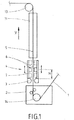
- Fig. 1 is sketched a hot-dip coating plant, which serves for coating a strip 1 with a coating metal.
- the tape 1 is introduced in the embodiment in a known manner in a coating container 2, in which liquid coating material is contained.
- a deflection of the belt 1 in the vertical direction V by means of a deflection roller 14 is made.
- the CVGL method can also be used in the same way, in which the band 1 enters the coating container 2 vertically from below and the bottom opening is sealed by means of an electromagnetic shutter.
- a wiping nozzle 3 Above the wiping nozzle 3 there is a device 4 for stabilizing the band 1.
- This device 4 has as its core two electro-magnets 6 arranged on both sides of the belt 1. With these devices it is achieved that the belt is deliberately subjected to magnetic forces such that it is held in a symmetrical center position 5 of the device.
- means 7 are provided with which the vertical distance H of the magnets 6 can be set by the wiper 3 targeted. This is indicated in Fig. 1 with the double arrows next to the magnets 6 and in that the magnets 6 are sketched once (in a middle position) with solid lines and in two further alternative positions with dashed lines, namely in a lower position near the wiping nozzle 3 and in an upper position at the upper end of the movement, which can be accomplished with the means 7.
- the distance of the magnets 6 from the upper end of the wiper 3 is indicated by H and indicates how far the magnets 6 are lifted by the means 7.
- a cooling section 11 is provided for the band 1.
- the band 1 is deflected by a deflection roller 13 in the horizontal.
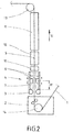
- Fig. 2 is an alternative solution outlined here compared with Fig. 1 an inductive heating device 10 is provided above the belt stabilization 4, with a Galvannealing process can be performed in a conventional manner. Between the heating element 10 and the cooling section 11 is still a holding furnace 12th
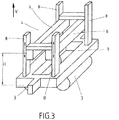
- Fig. 3 An idea of the structural design of the proposed device goes out Fig. 3 out.
- the wiping nozzle 3 is arranged on a frame structure 9, on which four lifting elements 8 are fastened, with which the magnets 6 can be raised or lowered relative to the wiping nozzle 3.
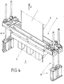
- FIG. 4 Further details of the structural design go out Fig. 4 out.
- four lifting elements 8 - in the present case designed as mechanical actuators in the form of spindle-nut systems - are used to the Move magnets 6 in the vertical direction V or adjust.
- the wiping nozzles 3 are not shown here; they are in the lower part of the illustration according to Fig. 4 ,
- the position of the strip stabilization is also tracked by the mechanical coupling of the strip stabilization magnets.
- the effect of band stabilization in the region of the wiper nozzle 3 is reduced in this case, but it does not go away because of the optimal position calculation by a mathematical model used here.
- the magnets 6 are positioned closer to the heating elements 10 (GA inductors) than to the wiping nozzle 3, but taking into account the physical action in both directions.
- the focus of the stabilizing effect is on minimizing tape movement within the wiping die 3.
- the position of the magnets 6 of the belt stabilization in the region of the wiping nozzle 3 is selected.
- the guide rollers in front of the heating element which are used in previously known systems to stabilize the belt, are no longer necessary, since now the stabilizing effect can be influenced in a targeted manner in the entire height range between the wiper and the heating element.
- the means 7 also advantageously allow a manual cleaning of the wiper 3 during operation.
- the belt stabilization or the magnets 6 are moved to an elevated position, but without losing the stabilizing effect. This is not possible with previously known systems.
- the maintenance personnel obtains free access to the scraper nozzle 3 and therefore can clean the nozzle lips manually. This requirement is met with every hot dip galvanizing line.
- the positioning of the belt stabilizing magnets 6 is as explained with a device which may have two guides, holders and corresponding clamping devices which cause the tensioning of the system and thus the parallel alignment of the belt stabilization (the magnets 6) to the belt or wiper support system.
- This band-stabilizing position changing device is fixedly mounted on the scraping nozzle 3, which includes a frame structure with alignment members.
- the principle is thus a frame construction, which in turn is firmly connected to the basic frame construction of the wiper nozzle 3. This is done with the alignment of the wiper 3 to the band 1 also always a synchronous alignment of the magnets 6 of the band stabilization to the band. 1
Landscapes
- Chemical & Material Sciences (AREA)
- Chemical Kinetics & Catalysis (AREA)
- Engineering & Computer Science (AREA)
- Materials Engineering (AREA)
- Mechanical Engineering (AREA)
- Metallurgy (AREA)
- Organic Chemistry (AREA)
- Coating With Molten Metal (AREA)
- Coating Apparatus (AREA)
- Application Of Or Painting With Fluid Materials (AREA)
Priority Applications (1)
| Application Number | Priority Date | Filing Date | Title |
|---|---|---|---|
| PL10774210T PL2496728T3 (pl) | 2009-11-04 | 2010-11-04 | Urządzenie do powlekania taśmy metalowej i sposób do niego |
Applications Claiming Priority (2)
| Application Number | Priority Date | Filing Date | Title |
|---|---|---|---|
| DE102009051932A DE102009051932A1 (de) | 2009-11-04 | 2009-11-04 | Vorrichtung zum Beschichten eines metallischen Bandes und Verfahren hierfür |
| PCT/EP2010/066810 WO2011054902A1 (de) | 2009-11-04 | 2010-11-04 | Vorrichtung zum beschichten eines metallischen bandes und verfahren hierfür |
Publications (2)
| Publication Number | Publication Date |
|---|---|
| EP2496728A1 EP2496728A1 (de) | 2012-09-12 |
| EP2496728B1 true EP2496728B1 (de) | 2018-01-03 |
Family
ID=43334557
Family Applications (1)
| Application Number | Title | Priority Date | Filing Date |
|---|---|---|---|
| EP10774210.8A Active EP2496728B1 (de) | 2009-11-04 | 2010-11-04 | Vorrichtung zum beschichten eines metallischen bandes und verfahren hierfür |
Country Status (11)
| Country | Link |
|---|---|
| EP (1) | EP2496728B1 (pl) |
| JP (1) | JP5663763B2 (pl) |
| KR (1) | KR101421981B1 (pl) |
| CN (1) | CN102597295B (pl) |
| CA (1) | CA2794925C (pl) |
| DE (1) | DE102009051932A1 (pl) |
| ES (1) | ES2660746T3 (pl) |
| HU (1) | HUE038462T2 (pl) |
| PL (1) | PL2496728T3 (pl) |
| TR (1) | TR201802499T4 (pl) |
| WO (1) | WO2011054902A1 (pl) |
Families Citing this family (9)
| Publication number | Priority date | Publication date | Assignee | Title |
|---|---|---|---|---|
| NO2786187T3 (pl) | 2014-11-21 | 2018-07-28 | ||
| DE102014225516B3 (de) | 2014-11-21 | 2016-03-31 | Fontaine Engineering Und Maschinen Gmbh | Verfahren und Vorrichtung zum Beschichten eines Metallbandes |
| DE102015216721B3 (de) | 2015-09-01 | 2016-11-24 | Fontaine Engineering Und Maschinen Gmbh | Vorrichtung zum Behandeln eines Metallbandes |
| DE102016222230A1 (de) * | 2016-08-26 | 2018-03-01 | Sms Group Gmbh | Verfahren und Beschichtungseinrichtung zum Beschichten eines Metallbandes |
| DE102017109559B3 (de) | 2017-05-04 | 2018-07-26 | Fontaine Engineering Und Maschinen Gmbh | Vorrichtung zum Behandeln eines Metallbandes |
| DE102018215100A1 (de) * | 2018-05-28 | 2019-11-28 | Sms Group Gmbh | Vakuumbeschichtungsanlage, und Verfahren zum Beschichten eines bandförmigen Materials |
| DE102018219134B3 (de) * | 2018-11-09 | 2020-01-30 | Thyssenkrupp Ag | Vorrichtung und Verfahren zur thermischen Behandlung einer Oberfläche eines bewegten Metallbandes |
| CN109526081A (zh) * | 2018-12-27 | 2019-03-26 | 邵阳高华工贸实业有限公司 | 一种用于钢筋生产的感应加热设备及方法 |
| IT201900023484A1 (it) * | 2019-12-10 | 2021-06-10 | Danieli Off Mecc | Apparato di stabilizzazione |
Family Cites Families (16)
| Publication number | Priority date | Publication date | Assignee | Title |
|---|---|---|---|---|
| JPH0681093A (ja) * | 1992-08-31 | 1994-03-22 | Kawasaki Steel Corp | ストリップの溶融金属メッキ設備 |
| DE4344939C1 (de) | 1993-12-23 | 1995-02-09 | Mannesmann Ag | Verfahren zum prozeßgerechten Regeln einer Anlage zum Beschichten von bandförmigem Gut |
| DE19535854C2 (de) | 1995-09-18 | 1997-12-11 | Mannesmann Ag | Verfahren zur Bandstabilisierung in einer Anlage zum Beschichten von bandförmigem Gut |
| KR100207710B1 (ko) * | 1996-12-27 | 1999-07-15 | 윤종용 | 개인휴대형 정보 단말기의 프린트 장치 및 방법 |
| JPH116046A (ja) | 1997-06-18 | 1999-01-12 | Nippon Steel Corp | 連続溶融金属メッキラインのドロス除去方法及び装置 |
| FR2797277A1 (fr) | 1999-08-05 | 2001-02-09 | Lorraine Laminage | Procede et dispositif de realisation en continu d'un revetement de surface metallique sur une tole en defilement |
| JP2001150015A (ja) * | 1999-11-30 | 2001-06-05 | Shinko Electric Co Ltd | 鋼板の位置・振動制御装置 |
| SE0002889L (sv) | 2000-08-11 | 2002-02-12 | Abb Ab | En anordning och ett förfarande för styrning av tjockleken av en beläggning på ett metalliskt föremål |
| JP4547818B2 (ja) * | 2001-03-16 | 2010-09-22 | Jfeスチール株式会社 | 溶融めっき鋼板のめっき付着量制御方法 |
| JP4450662B2 (ja) * | 2004-04-05 | 2010-04-14 | 三菱日立製鉄機械株式会社 | 鋼板の制振装置 |
| SE527507C2 (sv) * | 2004-07-13 | 2006-03-28 | Abb Ab | En anordning och ett förfarande för stabilisering av ett metalliskt föremål samt en användning av anordningen |
| DE102005060058B4 (de) * | 2005-12-15 | 2016-01-28 | Emg Automation Gmbh | Verfahren und Vorrichtung zum Stabilisieren eines Bandes |
| DE102006052000A1 (de) * | 2006-11-03 | 2008-05-08 | Emg Automation Gmbh | Vorrichtung zum Stabilisieren des Laufs eines Metallbandes |
| EP2188403B1 (de) * | 2007-08-22 | 2012-07-25 | SMS Siemag AG | Verfahren und schmelztauchveredelungsanlage zur bandstabilisierung eines zwischen abstreifdüsen der schmelztauchveredelungsanlage geführten, mit einer beschichtung versehenen bandes |
| DE102007045202A1 (de) * | 2007-09-21 | 2009-04-02 | Sms Demag Ag | Vorrichtung zur Bandkantenstabilisierung |
| KR100899550B1 (ko) * | 2007-11-01 | 2009-05-26 | 현대하이스코 주식회사 | 고속 합금화 용융 아연 도금강판의 제조방법 |
-
2009
- 2009-11-04 DE DE102009051932A patent/DE102009051932A1/de not_active Withdrawn
-
2010
- 2010-11-04 CN CN201080050673.8A patent/CN102597295B/zh active Active
- 2010-11-04 TR TR2018/02499T patent/TR201802499T4/tr unknown
- 2010-11-04 JP JP2012537399A patent/JP5663763B2/ja active Active
- 2010-11-04 CA CA2794925A patent/CA2794925C/en active Active
- 2010-11-04 EP EP10774210.8A patent/EP2496728B1/de active Active
- 2010-11-04 PL PL10774210T patent/PL2496728T3/pl unknown
- 2010-11-04 WO PCT/EP2010/066810 patent/WO2011054902A1/de not_active Ceased
- 2010-11-04 ES ES10774210.8T patent/ES2660746T3/es active Active
- 2010-11-04 KR KR1020127011678A patent/KR101421981B1/ko active Active
- 2010-11-04 HU HUE10774210A patent/HUE038462T2/hu unknown
Also Published As
| Publication number | Publication date |
|---|---|
| KR101421981B1 (ko) | 2014-08-13 |
| CN102597295B (zh) | 2015-04-22 |
| WO2011054902A1 (de) | 2011-05-12 |
| KR20120063550A (ko) | 2012-06-15 |
| ES2660746T3 (es) | 2018-03-26 |
| TR201802499T4 (tr) | 2018-03-21 |
| EP2496728A1 (de) | 2012-09-12 |
| DE102009051932A1 (de) | 2011-05-05 |
| CA2794925C (en) | 2014-08-19 |
| JP5663763B2 (ja) | 2015-02-04 |
| CN102597295A (zh) | 2012-07-18 |
| CA2794925A1 (en) | 2011-05-12 |
| HUE038462T2 (hu) | 2018-10-29 |
| JP2013510236A (ja) | 2013-03-21 |
| PL2496728T3 (pl) | 2018-06-29 |
Similar Documents
| Publication | Publication Date | Title |
|---|---|---|
| EP2496728B1 (de) | Vorrichtung zum beschichten eines metallischen bandes und verfahren hierfür | |
| EP3234204B1 (de) | Vorrichtung und verfahren zur kontinuierlichen behandlung eines metallbandes | |
| EP3221486B1 (de) | Verfahren und vorrichtung zum beschichten eines metallbandes mit einem zunächst noch flüssigen beschichtungsmaterial | |
| WO2007039102A1 (de) | Verfahren und vorrichtung zum reinigen von brammen, dünnbrammen, profilen oder dergleichen | |
| EP2344287B1 (de) | Verfahren und vorrichtung zum kühlen eines vorbandes oder bandes eines metallstrangs in einem warmwalzwerk | |
| WO2010149351A1 (de) | Vorrichtung und verfahren zum horizontalen giessen eines metallbandes | |
| WO2009039949A1 (de) | Vorrichtung und verfahren zur bandkantenstabilisierung | |
| EP2190602A1 (de) | Vorrichtung und verfahren zur bandlageregelung | |
| DE69426357T2 (de) | Vorrichtung und Verfahren zum Kontrollieren der Beschichtungsgewicht eines metallüberzuges mittels Blasdüsen | |
| EP3619333B1 (de) | Vorrichtung zum behandeln eines metallbandes | |
| DE102022100820B3 (de) | Stabilisierungsvorrichtung und Sensoraufbau für fortlaufend bewegte Metallbänder | |
| DE1508451A1 (de) | Verfahren und Vorrichtung zum Abschrecken | |
| DE2656524B2 (de) | Verfahren zum einseitigen Beschichten eines Metallbandes mit schmelzflüssigem Metall | |
| EP0721813A1 (de) | Vorrichtung zum Führen von warmgewalztem Band durch einen Induktor | |
| EP1563113B1 (de) | Verfahren und vorrichtung zur schmelztauchbeschichtung eines metallstranges | |
| WO2022058152A1 (de) | Verfahren und sprüheinrichtung zur thermischen oberflächenbehandlung eines metallischen produkts | |
| DE102013212952A1 (de) | Vorrichtung und Verfahren zum Stützen eines Stranges beim Stranggießen | |
| WO2009068232A1 (de) | Verfahren und vorrichtung zum vergleichmässigen des erstarrungsvorganges eines insbesondere beim strang- oder bandgiessen erzeugten schmelzflüssigen metalles | |
| DE19953915A1 (de) | Verfahren und Vorrichtung zum Bearbeiten eines Warmbandes auf dem Auslaufrollgang einer Warmbandstraße | |
| DE10330656A1 (de) | Vorrichtung zur Schmelztauchbeschichtung eines Metallstranges | |
| AT410408B (de) | Verfahren zum stranggiessen von metallschmelzen | |
| DE102023115850A1 (de) | Induktionsheizvorrichtung, Verfahren zum induktiven Erwärmen, Produktionslinie und Verwendung | |
| DE102023121444A1 (de) | Beschichtungsvorrichtung für Metallbänder mit Bandstabilisierungsvorrichtung | |
| DE102004061080A1 (de) | Verfahren und Vorrichtung zum Bandgießen von Metallen | |
| DE102010063093B4 (de) | Vorrichtung und Verfahren zum horizontalen Gießen von Metallbändern |
Legal Events
| Date | Code | Title | Description |
|---|---|---|---|
| PUAI | Public reference made under article 153(3) epc to a published international application that has entered the european phase |
Free format text: ORIGINAL CODE: 0009012 |
|
| 17P | Request for examination filed |
Effective date: 20120423 |
|
| AK | Designated contracting states |
Kind code of ref document: A1 Designated state(s): AL AT BE BG CH CY CZ DE DK EE ES FI FR GB GR HR HU IE IS IT LI LT LU LV MC MK MT NL NO PL PT RO RS SE SI SK SM TR |
|
| DAX | Request for extension of the european patent (deleted) | ||
| RAP1 | Party data changed (applicant data changed or rights of an application transferred) |
Owner name: FONTAINE ENGINEERING UND MASCHINEN GMBH |
|
| 17Q | First examination report despatched |
Effective date: 20170413 |
|
| GRAP | Despatch of communication of intention to grant a patent |
Free format text: ORIGINAL CODE: EPIDOSNIGR1 |
|
| INTG | Intention to grant announced |
Effective date: 20170628 |
|
| GRAS | Grant fee paid |
Free format text: ORIGINAL CODE: EPIDOSNIGR3 |
|
| GRAA | (expected) grant |
Free format text: ORIGINAL CODE: 0009210 |
|
| AK | Designated contracting states |
Kind code of ref document: B1 Designated state(s): AL AT BE BG CH CY CZ DE DK EE ES FI FR GB GR HR HU IE IS IT LI LT LU LV MC MK MT NL NO PL PT RO RS SE SI SK SM TR |
|
| REG | Reference to a national code |
Ref country code: GB Ref legal event code: FG4D Free format text: NOT ENGLISH |
|
| REG | Reference to a national code |
Ref country code: CH Ref legal event code: EP Ref country code: AT Ref legal event code: REF Ref document number: 960341 Country of ref document: AT Kind code of ref document: T Effective date: 20180115 |
|
| REG | Reference to a national code |
Ref country code: IE Ref legal event code: FG4D Free format text: LANGUAGE OF EP DOCUMENT: GERMAN |
|
| REG | Reference to a national code |
Ref country code: DE Ref legal event code: R096 Ref document number: 502010014536 Country of ref document: DE |
|
| REG | Reference to a national code |
Ref country code: ES Ref legal event code: FG2A Ref document number: 2660746 Country of ref document: ES Kind code of ref document: T3 Effective date: 20180326 |
|
| REG | Reference to a national code |
Ref country code: SE Ref legal event code: TRGR |
|
| REG | Reference to a national code |
Ref country code: NL Ref legal event code: FP |
|
| REG | Reference to a national code |
Ref country code: LT Ref legal event code: MG4D |
|
| PG25 | Lapsed in a contracting state [announced via postgrant information from national office to epo] |
Ref country code: LT Free format text: LAPSE BECAUSE OF FAILURE TO SUBMIT A TRANSLATION OF THE DESCRIPTION OR TO PAY THE FEE WITHIN THE PRESCRIBED TIME-LIMIT Effective date: 20180103 Ref country code: HR Free format text: LAPSE BECAUSE OF FAILURE TO SUBMIT A TRANSLATION OF THE DESCRIPTION OR TO PAY THE FEE WITHIN THE PRESCRIBED TIME-LIMIT Effective date: 20180103 Ref country code: NO Free format text: LAPSE BECAUSE OF FAILURE TO SUBMIT A TRANSLATION OF THE DESCRIPTION OR TO PAY THE FEE WITHIN THE PRESCRIBED TIME-LIMIT Effective date: 20180403 Ref country code: CY Free format text: LAPSE BECAUSE OF FAILURE TO SUBMIT A TRANSLATION OF THE DESCRIPTION OR TO PAY THE FEE WITHIN THE PRESCRIBED TIME-LIMIT Effective date: 20180103 |
|
| REG | Reference to a national code |
Ref country code: SK Ref legal event code: T3 Ref document number: E 27075 Country of ref document: SK |
|
| PG25 | Lapsed in a contracting state [announced via postgrant information from national office to epo] |
Ref country code: LV Free format text: LAPSE BECAUSE OF FAILURE TO SUBMIT A TRANSLATION OF THE DESCRIPTION OR TO PAY THE FEE WITHIN THE PRESCRIBED TIME-LIMIT Effective date: 20180103 Ref country code: BG Free format text: LAPSE BECAUSE OF FAILURE TO SUBMIT A TRANSLATION OF THE DESCRIPTION OR TO PAY THE FEE WITHIN THE PRESCRIBED TIME-LIMIT Effective date: 20180403 Ref country code: RS Free format text: LAPSE BECAUSE OF FAILURE TO SUBMIT A TRANSLATION OF THE DESCRIPTION OR TO PAY THE FEE WITHIN THE PRESCRIBED TIME-LIMIT Effective date: 20180103 Ref country code: IS Free format text: LAPSE BECAUSE OF FAILURE TO SUBMIT A TRANSLATION OF THE DESCRIPTION OR TO PAY THE FEE WITHIN THE PRESCRIBED TIME-LIMIT Effective date: 20180503 Ref country code: GR Free format text: LAPSE BECAUSE OF FAILURE TO SUBMIT A TRANSLATION OF THE DESCRIPTION OR TO PAY THE FEE WITHIN THE PRESCRIBED TIME-LIMIT Effective date: 20180404 |
|
| PG25 | Lapsed in a contracting state [announced via postgrant information from national office to epo] |
Ref country code: MT Free format text: LAPSE BECAUSE OF FAILURE TO SUBMIT A TRANSLATION OF THE DESCRIPTION OR TO PAY THE FEE WITHIN THE PRESCRIBED TIME-LIMIT Effective date: 20180103 |
|
| REG | Reference to a national code |
Ref country code: DE Ref legal event code: R097 Ref document number: 502010014536 Country of ref document: DE |
|
| REG | Reference to a national code |
Ref country code: HU Ref legal event code: AG4A Ref document number: E038462 Country of ref document: HU |
|
| PG25 | Lapsed in a contracting state [announced via postgrant information from national office to epo] |
Ref country code: AL Free format text: LAPSE BECAUSE OF FAILURE TO SUBMIT A TRANSLATION OF THE DESCRIPTION OR TO PAY THE FEE WITHIN THE PRESCRIBED TIME-LIMIT Effective date: 20180103 Ref country code: EE Free format text: LAPSE BECAUSE OF FAILURE TO SUBMIT A TRANSLATION OF THE DESCRIPTION OR TO PAY THE FEE WITHIN THE PRESCRIBED TIME-LIMIT Effective date: 20180103 Ref country code: RO Free format text: LAPSE BECAUSE OF FAILURE TO SUBMIT A TRANSLATION OF THE DESCRIPTION OR TO PAY THE FEE WITHIN THE PRESCRIBED TIME-LIMIT Effective date: 20180103 |
|
| PLBE | No opposition filed within time limit |
Free format text: ORIGINAL CODE: 0009261 |
|
| STAA | Information on the status of an ep patent application or granted ep patent |
Free format text: STATUS: NO OPPOSITION FILED WITHIN TIME LIMIT |
|
| PG25 | Lapsed in a contracting state [announced via postgrant information from national office to epo] |
Ref country code: DK Free format text: LAPSE BECAUSE OF FAILURE TO SUBMIT A TRANSLATION OF THE DESCRIPTION OR TO PAY THE FEE WITHIN THE PRESCRIBED TIME-LIMIT Effective date: 20180103 Ref country code: SM Free format text: LAPSE BECAUSE OF FAILURE TO SUBMIT A TRANSLATION OF THE DESCRIPTION OR TO PAY THE FEE WITHIN THE PRESCRIBED TIME-LIMIT Effective date: 20180103 Ref country code: CZ Free format text: LAPSE BECAUSE OF FAILURE TO SUBMIT A TRANSLATION OF THE DESCRIPTION OR TO PAY THE FEE WITHIN THE PRESCRIBED TIME-LIMIT Effective date: 20180103 |
|
| 26N | No opposition filed |
Effective date: 20181005 |
|
| PG25 | Lapsed in a contracting state [announced via postgrant information from national office to epo] |
Ref country code: SI Free format text: LAPSE BECAUSE OF FAILURE TO SUBMIT A TRANSLATION OF THE DESCRIPTION OR TO PAY THE FEE WITHIN THE PRESCRIBED TIME-LIMIT Effective date: 20180103 |
|
| REG | Reference to a national code |
Ref country code: CH Ref legal event code: PL |
|
| PG25 | Lapsed in a contracting state [announced via postgrant information from national office to epo] |
Ref country code: MC Free format text: LAPSE BECAUSE OF FAILURE TO SUBMIT A TRANSLATION OF THE DESCRIPTION OR TO PAY THE FEE WITHIN THE PRESCRIBED TIME-LIMIT Effective date: 20180103 |
|
| REG | Reference to a national code |
Ref country code: IE Ref legal event code: MM4A |
|
| PG25 | Lapsed in a contracting state [announced via postgrant information from national office to epo] |
Ref country code: LI Free format text: LAPSE BECAUSE OF NON-PAYMENT OF DUE FEES Effective date: 20181130 Ref country code: CH Free format text: LAPSE BECAUSE OF NON-PAYMENT OF DUE FEES Effective date: 20181130 |
|
| PG25 | Lapsed in a contracting state [announced via postgrant information from national office to epo] |
Ref country code: IE Free format text: LAPSE BECAUSE OF NON-PAYMENT OF DUE FEES Effective date: 20181104 |
|
| PG25 | Lapsed in a contracting state [announced via postgrant information from national office to epo] |
Ref country code: PT Free format text: LAPSE BECAUSE OF FAILURE TO SUBMIT A TRANSLATION OF THE DESCRIPTION OR TO PAY THE FEE WITHIN THE PRESCRIBED TIME-LIMIT Effective date: 20180103 |
|
| PG25 | Lapsed in a contracting state [announced via postgrant information from national office to epo] |
Ref country code: MK Free format text: LAPSE BECAUSE OF NON-PAYMENT OF DUE FEES Effective date: 20180103 |
|
| P01 | Opt-out of the competence of the unified patent court (upc) registered |
Effective date: 20230517 |
|
| PGFP | Annual fee paid to national office [announced via postgrant information from national office to epo] |
Ref country code: DE Payment date: 20241121 Year of fee payment: 15 |
|
| PGFP | Annual fee paid to national office [announced via postgrant information from national office to epo] |
Ref country code: BE Payment date: 20241120 Year of fee payment: 15 Ref country code: PL Payment date: 20241025 Year of fee payment: 15 Ref country code: FI Payment date: 20241122 Year of fee payment: 15 |
|
| PGFP | Annual fee paid to national office [announced via postgrant information from national office to epo] |
Ref country code: GB Payment date: 20241120 Year of fee payment: 15 |
|
| PGFP | Annual fee paid to national office [announced via postgrant information from national office to epo] |
Ref country code: FR Payment date: 20241128 Year of fee payment: 15 |
|
| PGFP | Annual fee paid to national office [announced via postgrant information from national office to epo] |
Ref country code: AT Payment date: 20241121 Year of fee payment: 15 |
|
| PGFP | Annual fee paid to national office [announced via postgrant information from national office to epo] |
Ref country code: SK Payment date: 20241029 Year of fee payment: 15 |
|
| PGFP | Annual fee paid to national office [announced via postgrant information from national office to epo] |
Ref country code: IT Payment date: 20241126 Year of fee payment: 15 Ref country code: ES Payment date: 20241230 Year of fee payment: 15 |
|
| PGFP | Annual fee paid to national office [announced via postgrant information from national office to epo] |
Ref country code: SE Payment date: 20241120 Year of fee payment: 15 |
|
| PGFP | Annual fee paid to national office [announced via postgrant information from national office to epo] |
Ref country code: TR Payment date: 20241030 Year of fee payment: 15 |
|
| PGFP | Annual fee paid to national office [announced via postgrant information from national office to epo] |
Ref country code: HU Payment date: 20251121 Year of fee payment: 16 |
|
| PGFP | Annual fee paid to national office [announced via postgrant information from national office to epo] |
Ref country code: LU Payment date: 20251119 Year of fee payment: 16 Ref country code: NL Payment date: 20251119 Year of fee payment: 16 |