EP2444853A2 - Entwicklervorrichtung und Bilderzeugungsvorrichtung damit - Google Patents
Entwicklervorrichtung und Bilderzeugungsvorrichtung damit Download PDFInfo
- Publication number
- EP2444853A2 EP2444853A2 EP11180162A EP11180162A EP2444853A2 EP 2444853 A2 EP2444853 A2 EP 2444853A2 EP 11180162 A EP11180162 A EP 11180162A EP 11180162 A EP11180162 A EP 11180162A EP 2444853 A2 EP2444853 A2 EP 2444853A2
- Authority
- EP
- European Patent Office
- Prior art keywords
- developer
- development
- transport system
- agitation container
- development device
- Prior art date
- Legal status (The legal status is an assumption and is not a legal conclusion. Google has not performed a legal analysis and makes no representation as to the accuracy of the status listed.)
- Withdrawn
Links
- 238000011161 development Methods 0.000 title claims abstract description 211
- 238000013019 agitation Methods 0.000 claims abstract description 69
- 230000032258 transport Effects 0.000 description 75
- 238000012546 transfer Methods 0.000 description 51
- 238000000034 method Methods 0.000 description 30
- 230000008569 process Effects 0.000 description 29
- 108091008695 photoreceptors Proteins 0.000 description 26
- 230000007246 mechanism Effects 0.000 description 14
- 230000004913 activation Effects 0.000 description 8
- 230000005484 gravity Effects 0.000 description 8
- 238000011144 upstream manufacturing Methods 0.000 description 8
- 230000004888 barrier function Effects 0.000 description 7
- 238000004140 cleaning Methods 0.000 description 6
- 230000003247 decreasing effect Effects 0.000 description 6
- 238000010586 diagram Methods 0.000 description 5
- 238000007664 blowing Methods 0.000 description 4
- 238000007599 discharging Methods 0.000 description 4
- 239000002245 particle Substances 0.000 description 4
- 230000008901 benefit Effects 0.000 description 2
- 230000008859 change Effects 0.000 description 2
- 238000002474 experimental method Methods 0.000 description 2
- 238000005192 partition Methods 0.000 description 2
- 238000012545 processing Methods 0.000 description 2
- 238000013459 approach Methods 0.000 description 1
- 230000005540 biological transmission Effects 0.000 description 1
- 230000000593 degrading effect Effects 0.000 description 1
- 230000001419 dependent effect Effects 0.000 description 1
- 238000013461 design Methods 0.000 description 1
- 238000001514 detection method Methods 0.000 description 1
- 238000005259 measurement Methods 0.000 description 1
- 230000003287 optical effect Effects 0.000 description 1
- 238000003825 pressing Methods 0.000 description 1
- 230000002265 prevention Effects 0.000 description 1
- 239000002699 waste material Substances 0.000 description 1
Images


Classifications
-
- G—PHYSICS
- G03—PHOTOGRAPHY; CINEMATOGRAPHY; ANALOGOUS TECHNIQUES USING WAVES OTHER THAN OPTICAL WAVES; ELECTROGRAPHY; HOLOGRAPHY
- G03G—ELECTROGRAPHY; ELECTROPHOTOGRAPHY; MAGNETOGRAPHY
- G03G15/00—Apparatus for electrographic processes using a charge pattern
- G03G15/06—Apparatus for electrographic processes using a charge pattern for developing
- G03G15/08—Apparatus for electrographic processes using a charge pattern for developing using a solid developer, e.g. powder developer
- G03G15/0822—Arrangements for preparing, mixing, supplying or dispensing developer
- G03G15/0877—Arrangements for metering and dispensing developer from a developer cartridge into the development unit
- G03G15/0879—Arrangements for metering and dispensing developer from a developer cartridge into the development unit for dispensing developer from a developer cartridge not directly attached to the development unit
Definitions
- the present invention relates to a development device and an image forming apparatus incorporating the development device, such as a copier, a printer, a facsimile machine, a plotter, or a multifunction machine capable of at least two of these, and more particularly, to a development device including a developer agitation container separated from a development portion and an air circulation mechanism for circulating developer between the developer agitation container and the development portion
- Known development devices included in electrophotographic image forming apparatuses employ a configuration in which supplying developer (toner) to a photoreceptor drum functioning as a latent image carrier, on the one hand, and mixing and agitating the developer and the supplied toner on the other are performed simultaneously in a development device housed in a single casing.
- the development device includes at least two conveyance screws that transport the developer in opposite directions, thus circulating the developer inside the development device.
- an agitation container to agitate the developer is provided separately from the part of the device that actually develops the image (a "development portion") with the developer that has been sufficiently agitated in the agitation portion being conveyed to the development portion.
- This system has the advantage that, since the agitation container is separated from the development portion, the capacity of the development portion can be minimized, thus minimizing the proportion of the development portion occupying the area near the photoreceptor drum.
- an efficient way to convey the developer from the agitation container is by a pneumatic system to convey the developer by air from the agitation container. As above-described pneumatic system used for the development device, several approaches are proposed.
- this failure occurs most readily when the development device is activated. This is because any developer remaining in the tube functioning as the transport path after a previous developing process is packed together under its own weight, and bulk density of the developer is increased, clogging the tube. The clogging causes a delay until it is dissolved and the bulk density of the developer is decreased so that the developer can be transported through the tube and the conveyance of the developer is started.
- the developer in the development portion is circulated by the conveyance screws, and then is moved back to the agitation container through a collection path connected to the development portion. Consequently, the amount of the developer in the development portion is decreased, and in the worst case, the developer may be completely gone from the development portion. In this case, the transported air is blown to a space and the opening that has hitherto been blocked by the developer, and the developer and the toner in the development portion becomes easily blown out through the opening. In some cases, the amount of the scattering developer is dozens of times the amount thereof when the opening is blocked by the developer.
- the delay until the clog is dissolved and the bulk density is decreased to a state in which the developer can be transported by the air varies depending on a concentration of toner in the developer as well as how long the developer has been left sitting and in what state. Consequently, more reliable prevention of the depletion of the developer in the development portion is desired.
- a development device includes a development portion, a developer agitation container, a transport system, and a developer retainer.
- the development portion develops a latent image formed on a latent image carrier with developer, disposed close to the latent image carrier.
- the developer agitation container agitates the developer and is provided separately from the development portion.
- the transport system connects the development portion and the developer agitation container, through which the developer is transported from the developer agitation container to the development portion by air.
- the developer retainer temporarily retains the developer, disposed downstream from the transport system, to which the developer remaining in the transport system escapes.
- an image forming apparatus includes a latent image carrier to carry a latent image and the above-described development device.
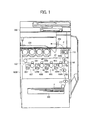
- FIG. 1 is a schematic diagram illustrating an image forming apparatus employing a development device according to exemplary embodiments
- FIG. 2 is a perspective view illustrating an entire configuration of the development device shown in FIG. 1 including a development portion and a developer agitation container;
- FIG. 3 is a schematic view illustrating an internal configuration of the development portion shown in FIG. 2 ;
- FIG. 4A is a cross-sectional view illustrating agitators provided in the developer agitation container shown in FIG. 2 when view from above;
- FIG. 4B is a schematic view illustrating an internal configuration of the developer agitation container, a rotary feeder, an air pump in the development device shown in FIG. 2 ;
- FIG. 5A is a block diagram illustrating configuration of a control mechanism to control operation in the development device show in FIG. 2 ;
- FIG. 5B is a timing chart illustrating operation in the development device controlled by the control mechanism shown in FIG. 5A ;
- FIG. 6 shows a relation between an arrival delay time and a bulk density while the arrival delay time was is changed to predetermined assumed bulk densities of the remaining developer
- FIG. 7 shows a relation between the arrival delay time and an amount of the developer remaining in a developer transport tube
- FIG. 8 shows an enlarged pneumatic mechanism in the development device shown in FIG. 2 ;
- FIG. 9 shows a relation between a stop delay time and the amount of the developer remaining in the developer transport tube before and after the developer is packed
- FIG. 10 shows a relation between the stop delay time and the arrival delay time before and after the developer is packed.
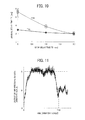
- FIG. 11 shows a relation between a time interval from when the air pump is activated to when the conveyance of the developer is started and an output value of an air pressure sensor.
- FIG. 1 an image forming apparatus that is an electrophotographic printer (hereinafter referred to as a printer) according to an illustrative embodiment of the present invention is described. It is to be noted that although the image forming apparatus of the present embodiment is a printer, the image forming apparatus of the present invention is not limited to a printer.
- An image forming apparatus 1000 in FIG. 1 includes an intermediate transfer unit 10.
- Image forming units 60Y, 60M, 60C, and 60Bk for respectively forming yellow, magenta, cyan, and black (hereinafter also simply "Y, M, C, and Bk") single-color toner images are disposed facing a lower surface of an intermediate transfer belt 80 in an intermediate transfer unit 1001.
- reference character suffixes Y, M, C, and Bk attached to an identical reference numeral indicate only that components indicated thereby are used for forming different single-color images, respectively, and hereinafter may be omitted when color discrimination is not necessary.
- each of the image forming units 60 includes a drum-shaped photoreceptor 1 functioning as a latent image carrier.
- a charging device, a development portion 2 of a development device 100, and a cleaning device are disposed around the photoreceptor 1 in each of the image forming units 60.
- image forming process including a charging process, an exposure process, a development process, a primary transfer process, and a cleaning process is executed, and thus a desired toner image is formed on the photoreceptor drum 1.
- the photoreceptor drum 1 is rotated clockwise by a driving mechanism, not shown, and, in the charging process, the surface of the photoreceptor drum 1 is uniformly charged in a portion facing the charging device.
- the laser beam scans the surface of the photoreceptor drum 1, thus forming a latent image on the portion receiving the laser beam.
- the latent image thereon is developed into a toner image with the toner included in developer supplied from the development device 100, that is, development process is executed.
- the surface of the photoreceptor drum 1 that carries the toner image developed in the development process reaches the portion facing the intermediate transfer belt 80 and primary transfer bias rollers 90, where the toner image on the photoreceptor drum 1 is transferred onto the intermediate transfer belt 80 and four toner image are superimposed one on another on the surface of intermediate transfer belt 80.
- the surface of the photoreceptor drum 1 reaches a portion facing the cleaning device, where un-transferred toner that remains on the surface of the photoreceptor drum 1 is collected by the cleaning device in the cleaning process.
- electrical potential on the surface of the photoreceptor drum 1 is first activated by a discharging roller, not shown. Undergoing these processes, the image forming process performed on the photoreceptor drum 1 is completed.
- a secondary transfer process is executed in the intermediate transfer unit 1001.
- a superimposed four-color toner on the intermediate transfer belt 80 is transferred onto a transfer sheet P, serving as a recording medium, at one time.
- the above-described image forming process is executed in both monochrome printing in black and white and multicolor printing.
- four image forming units 60Y, 60M, 60C, and 60Bk perform the above-described image forming processes, respectively.
- the exposure device optical writing member
- the exposure device positioned beneath the image forming units 6 irradiates the respective photoreceptor drums 1 in the image forming units 60 with the respective laser beams in accordance with image data.
- the toner images formed on the respective photoreceptor drums 1Y, 1M, 1C, and 1Bk in the development process are primarily transferred from the photoreceptor drums 1 and are superimposed one on another on the surface of the intermediate transfer belt 80.
- a multicolor (four-color) image is formed on the intermediate transfer belt 80.
- the intermediate transfer belt 80 is sandwiched between the primary transfer bias rollers 90Y, 90M, 90C, and 90Bk and the photoreceptor drums 1Y, 1M, 1C, and 1Bk, and primary transfer nips are formed therebetween, respectively.
- Each primary transfer bias roller 90 applies a transfer bias that has a reverse polarity (e.g., positive polarity) to the polarity of the toner to a backside (inner circumference face) of the intermediate transfer belt 80.
- the intermediate transfer belt 80 moves in a direction indicated by arrow shown in FIG. 1 and goes through the primary transfer nips sequentially, the respective toner images on the photoreceptor drums 1Y, 1M, 1C, and 1Bk are primarily transferred and are superimposed one on another on the surface of the intermediate transfer belt 80.
- the intermediate transfer belt 80 is sandwiched between a secondary transfer roller 190 and a secondary transfer bias roller 89, and a secondary transfer nip is formed therebetween.
- a secondary transfer nip is formed therebetween.
- a feeding device 260 is disposed in a lower portion of the image forming apparatus 1000 and contains multiple transfer sheets P.
- the transfer sheet P is fed one-by-one by a feed roller 270.
- the transfer sheet P thus fed is stopped by a pair of registration rollers 280, and then skew of the transfer sheet P is corrected, after which the pair of the registration rollers 280 transports the transfer sheet P toward the secondary transfer nip at an appropriate timing.
- the image is transferred onto the transfer sheet P at the secondary transfer nip.
- the secondary transfer nip in a case in which the image on the intermediate transfer belt 80 is the superimposed image, a desired multicolor image is transferred onto the transfer sheet P.
- the transfer sheet P onto which multicolor image is transferred at the secondary transfer nip is transported to a fixing device 110 positioned above the secondary transfer roller 190 in FIG. 1 , where the four-color toner image thus transferred is fixed on the surface of the transfer sheet P with heat and pressure in a fixing process.
- the transfer sheets P are discharged toward a discharge sheet tray 300 located on an upper portion of the image forming apparatus 1000 via a pair of discharging sheet rollers 290 and are stacked on the discharge sheet tray 300.
- the image forming apparatus 1000 further includes a scanner 320 that scans a document.
- FIG. 2 illustrates an entire configuration of the development device 100 according to the present embodiment.
- the development device 100 uses two-component developer including toner and carrier.
- the development device 100 shown in FIG. 2 includes the development portion 2 disposed close to the photoconductor drum 1 and a developer agitation container 40 provided separately from the development portion 2.
- the developer in the developer agitation container 40 is conveyed by air through a developer transport tube 5 and a developer drop tube 6.
- the developer transport tube 5 functions as a transport system.
- a developer supply tube 7 is connected to the developer drop tube 6.
- the developer supply tube 7 and a developer discharge tube 3 are provided on the development portion 2.
- a developer collection tube 4 is connected between the developer discharge tube 3 and the developer agitation container 40.
- the developer collection tube 4 and the developer discharging tube 3 function as a collection system.
- FIG. 3 shows the interior structure of the development portion 2.
- the development portion 2 executes the development process on the photoreceptor drums 1 by using two-component developer in which carrier particles and toner particles are mixed.
- the development portion 2 includes a development sleeve 20, conveyance screws 21 and 22, and a doctor blade 25.
- the development sleeve 20 carries the developer and is disposed facing the photoreceptor drum 1.
- the doctor blade 25 adjusts the amount of the developer carried on the development sleeve 20.
- the conveyance screws 21 and 22 are offset from the developer sleeve 20 so that they are located respectively higher than and lower than the developer sleeve 20.
- the development sleeve 20 includes a magnet and carries the developer to cause the toner in the developer to magnetically adhere to the electrostatic latent image formed on the photoconductor drum 1.
- the first conveyance screw 21 moves the developer supplied from front side (developer supply tube 7 side) toward the back side of the paper sheet on which FIG. 3 is drawn and the second conveyance screw 22 conveys the developer from the back side toward the front side of the paper sheet on which FIG. 3 is drawn (developer discharge tube 3 side).
- the development portion is surrounded by a casing 23.
- the interior of the casing 23 is divided into two chambers by a partition 24, and the first conveyance screw 21 is provided in a first chamber 26, and the second conveyance screw 22 is provided in a second chamber 27.
- the development sleeve 20 and the conveyance screws 21 and 22 are rotated by a development-portion driving motor 10 (see FIG. 2 ) via a drive transmission mechanism.
- the partition 24 is opened in the backside end so that the developer can be moved from the first chamber 26 including the first conveyance screw 21 to the second chamber 27 including the second conveyance screw 22.
- the developer supply tube 7 is provided in a front face of the first chamber 26, and the developer discharge tube 3 is provided in a front face of the second chamber 27.
- the doctor blade 25 to smooth the amount of the developer magnetically attracted by the development sleeve 20 to a uniform thickness is supported by the casing 23, which is disposed to a vicinity of the development sleeve 20.
- the casing 23 is covered the vicinity of the conveyance screws 21 and 22. However, the casing 23 is opened at a portion facing the photoreceptor drum 1 so as to supply the developer from the development sleeve 20 to the photoreceptor drum 1, and a gap is present between the casing 23 and the development sleeve 20 to pass the magnet brush of the developer standing on the development sleeve 20 through the gap.
- FIG. 4A is a cross-sectional diagram illustrating the developer container 40 when viewer from above.
- FIG. 4B illustrates an internal structure of the developer container 40, a rotary feeder 50, and an air pump 60.
- the developer container 40 has a container casing 40A that is shaped like an upright cylinder, a lower end of which forms a funnel, that is, a tapered portion of downwardly decreasing diameter.
- a supply opening 33 connected to the developer collection tube 4 is provided on a top of the developer casing 40A.
- a discharge opening 34 whose diameter is smallest in the developer container 40, provided at a bottom of the container casing 40A, is continuous with the rotary feeder 50.
- a screw agitator 43 that conveys the developer from bottom up, and two blade agitators 44 located outside of the screw agitator 43 are provided inside the container casing 40A of the developer agitation container 40.
- the screw agitator 43 extends vertically in a center portion of the container casing 40A, and the blade agitator 44 is integrally formed with an upper end blade 44A.
- the developer in the container casing 40A is mixed by rotating the agitators 43 and 44, as shown in FIG. 4A .
- the screw agitator 43 and the blade agitators 44 are rotated by an agitator driving motor 45. More particularly, the screw agitator 43 is directly connected to the agitator driving motor 45, and the blade agitators 44 is rotated while being decelerated by being decelerated gears 46a, 46b, 46c, and 46d.
- the developer in the development agitation container 40 is conveyed from the supply opening 33 to the discharge opening 34 by gravity.
- the developer agitation container 40 always contains the developer as a buffer, thus preventing the un-mixed developer from directly discharging outside.
- the developer lifted from bottom to top by the rotating the screw agitator 43 is moved downward with rotation of the blade agitators 44 that rotates outside of the screw agitator 43 and then is concentrated in the center portion that is the vicinity of the screw agitator 43.
- the developer is constantly moved by convection in the container casing 40A. Due to this convection, the developer is mixed uniformly in the entire container casing 40A.
- the developer of the present disclosure is the two-component developer including toner particles and carrier particles and the toner is charged by friction between the toner and the carrier, it is important for increasing the charging amount to increase contact probability between the toner and the carrier. More particularly, it has experimentally proven that the contact probability is increased by converting the developer, which alleviates the damage to the developer.
- the container casing 40A of the developer agitation container 40 is replenished with fresh toner from a toner hopper 30 as appropriate as the toner is consumed.
- a toner concentration sensor is provided in (or near) the development device 100. In this toner replenish operation, an output value obtained by the toner concentration sensor and a control value of the toner concentration of the developer contained in the development device 100 that is set to a predetermined value are compared. When the output value of the toner concentration sensor is lower than the control value, the developer agitation container 40 is replenished with the fresh toner.
- toner replenishment of the developer agitation container 40 when a driving motor 32 is rotated, and the fresh toner contained in the toner hopper 30 is transported by rotating a small screw conveyer provided inside a toner supply tube 31 that is connected to the container casing 40A of the developer agitation container 40.
- the small screw conveyer in the toner supply tube 31 is configured to transport the fresh toner in the toner hopper 30 at a constant amount.
- the rotary feeder 50 functioning as a developer feeder to supply the developer from the developer agitation container 40 to the developer transport tube 5, is provided.
- the rotary feeder 50 is continuous with the developer agitation container 40, and the developer agitated in the developer agitation container 40 is supplied to the rotary feeder 50.
- the developer feeder 50 can discharge the constant amount of the developer from the developer agitation container 40 while adjusting the amount of the developer. More specifically, a rotatable impeller 51 is provided inside a casing 50A of the rotary feeder 50 (see FIG. 4 ). The constant amount of the developer is discharged to the developer transport tube 5 by rotating the impeller 51 driven by a rotary-feeder driving motor 55 (see FIG. 2 ),
- a junction portion 52 is provided beneath the impeller 51.
- the junction portion 52 is connected to an air pipe 53 and an entrance tube 5A af the developer transport tube 5.
- An air supply tube 60A connects the air pump 60 and the junction portion 52.
- the air pump 60 functions as a pneumatic device to generate air to move the developer from the rotary feeder 50to the developer transport tube 5.
- the constant amount of the developer discharged by the impeller 51 is transported to the developer dropping tube 6 through the developer transport tube 5 by blowing air supplied from the air pump 60.
- the developer in the developer dropping tube 6 is transported to the development portion 2 through the developer supply tube 7. With this configuration, the developer is circulated between the developer agitation container 40 and the development portion 2.
- the slight gap is present between the casing 23 and the development sleeve 20.
- the gap is set for passing a magnetic brush standing on the development sleeve 20 that is adjusted by the doctor blade 25 through the gap between the casing 23 and the development sleeve 20. Accordingly, when the airflow used for the conveyance of the developer enters the development portion 2, the air is blown out of the gap and the developer may leak from the casing 23.
- the developer in the development portion 2 functions as a barrier.
- the developer used for the development in the development portion 2 is transported to the developer agitation container 40 through the developer discharge tube 3 and the developer collection tube 4, and the developer is sufficiently agitated with fresh toner and is properly electrically charged in the developer agitation container 40. Then, the developer is returned to the development portion 2 through the developer transport tube 5, and thus the development portion 2 executes stable development operation.
- the operation of the respective components in the development device 100 is controlled such that an outflow path through which the developer and the air leak out is always blocked by the developer functioning as the barrier whenever the air used for the conveyance of the developer enters the casing 23.
- FIG. 5A is a block diagram illustrating a configuration of a control mechanism to control the above-described operation.
- a control panel 201 e.g., sensors 202, and a computer (e.g., a PC as shown in FIG. 5A ) are connected to an input side of a controller 200.
- the development-portion driving motor 10 that drives screw conveyers 21 and 22 in the development portion 2, the agitator driving motor 45 provided in the developer agitation container 40, the rotary-feeder driving motor 55, and the air pump 60 are connected to an output side of the controller 200.
- the control panel 201 includes an activation switch to send commands to activate and stop operation of components (2, 40, 50, and 52) included in the development device 100 and components in the main unit image forming apparatus 1000.
- the operation sensors 202 include the developer concentration detection sensor and check the operation of the components in the development device 100 and devices involved in the image forming processing.
- the computer (PC) outputs an image forming processing command to the image forming apparatus 1000 externally.
- the controller 200 controls operation period including a stop time and an activation time in the respective components, such that the developer can be stopped based on predetermined conditions so as to prevent the air from leaking out of conveyance paths (developer transport tube 5, developer dropping tube 6, developer supply tube 7, developer discharge tube 3, developer collection tube 4) including the development portion 2 when the air is blow therein.
- FIG. 5B is a timing chart illustrating operation in the development device 100 controlled by the control mechanism shown in FIG. 5A . The reason for the above-described control is as follows:
- FIG. 6 shows a relation between the arrival delay time T1 and the bulk density as the arrival delay time T1 is changed to predetermined assumed bulk densities of remaining developer. In this measurement, the weight of remaining developer was constant.
- the arrival delay time T1 from the start of conveying the developer to the arrival of the developer to the developer supply tube 7 is increased. The bulk density is changed within a range from a maximum to a minimum use toner concentration.
- the bulk density of the developer is set from 1.7 g/ cm 3 (at maximum toner concentration) to 2.0 g/ cm 3 (at minimum toner concentration).
- the bulk density is changed depending on a weight of the developer and a state of the packed developer compressed under its own weight and by applying vibration.
- 2.2 g /cm 3 is a value when the developer is packed by pressing by applying vibration.
- the arrival delay time T1 varied from approximately 1 second to 8 second in a range of the assumed changed bulk density.
- the developer in the development portion 2 is depleted.
- the barrier formed by the developer that prevents the air from leaking outside is not present, the air for conveyance is blown outside from the development portion 2, which causes the toner to scatter.
- the amount of the scattering toner in a state in which the developer is deleted in the development portion 2 is ten times of amount in a state in which the developer is not depleted.
- activation time and stop time to activate and stop operation of the respective components in the development device 100 are set to ensure an amount of the developer remaining in the development portion 2 of the development device 100 in a first embodiment, which is described detail below...
- the controller 200 stops the rotary-feeder driving motor 55 that drives the rotary feeder 50. Then, the controller 200 stops the air pump 60 and the development-portion driving motor 10 that drives the development portion 2 after a predetermined delay time T2 (to be determined as described below) has elapsed as shown in FIG. 5B .
- the controller 200 stops the air pump 60, after the controller 201 stops the rotary feeder 50 and the developer in the developer transport tube 5 escapes to the developer supply tube 7 as a developer retainer.
- the agitator driving motor 45 that drives the agitators 43 and 44 in the agitation container 40 is stopped at the same time to the time when the rotary-feeder driving motor 55 in the present embodiment, the agitator driving motor 45 can be stopped at any time from when the development device 100 receives the command to stop the operation in the development device 100 to when the development device 100 is completely stopped.
- the movement of the developer under the control operation is described below.
- the developer is supplied from the rotary feeder 50 to the developer transport tube 5.
- the rotary-feeder driving motor 55 that drives the rotary feeder 50 is stopped, the supply of the developer from the rotary feeder 50 to the developer transport tube 5 is stopped.
- the developer transport tube 5 includes the entrance tube 5A, a vertical tube 5B, and a horizontal tube 5C.
- the developer from the entrance tube 5A is transported upward through the vertical tube 5B that is parallel to a gravity direction and then is transported sideward through the horizontal tube 5C that is connected to the vertical tube 5B, extending in a horizontal direction.
- the horizontal tube 5C is connected to the developer dropping tube 6 provided above the developer supply tube 7.
- the developer drops into the developer supply tube 7 by gravity through the developer dropping tube 6.
- the developer in the developer transport tube 5 is guided to the develop supply tube 7 functioning as the developer retainer (escape portion) that temporally retains the developer.
- the horizontal tube 5C extending in the substantially horizontal direction is located in an extremely downstream end in the developer transport tube 5, the developer transported downstream from the horizontal tube 5C is prevented from moving reversely to the vertical tube 5B by falling freely by gravity. Namely, the horizontal tube 5C is disposed downstream from the vertical tube 5B so that the developer is prevented from flowing in reverse from developer supply tube 7 (developer retainer) to the vertical tube 5B. Accordingly, the horizontal tube 5C that is the downstream end of the developer transport tube 5 and more downstream portion (the developer dropping tube 6, the developer supply tube 7) can be also used as the developer retainer (escape portion) of the developer. In order to prevent the backflow of the developer, it is preferable that an angle between the vertical tube 5B and the horizontal tube 5C is set smaller than a repose angle of the developer.
- a stop time of the development-portion driving motor 10 that drives the development portion 2 is set identical to a stop time of the air pump 60 so that the developer does not overflow in the developer supply tube 7. Accordingly, the developer escaped in the developer supply tube 7 is transported to the more downstream from the first transport screw 21 in the first chamber 26, the developer positioned close to the first transport screw 21 is transported to the second chamber 27, and the developer close to the second transport screw 22 is transported to the agitation container 40 through the developer discharge tube 3 and the developer collection tube 4 consequently.
- the casing 40A of the developer container 40 is dimensioned so that the casing 40A can hold as much as or greater than a volume of the developer escaped from the developer transport tube 5.
- a portion in which a capacity needed to hold the escaped developer is ensured (hereinafter just "escaped-developer containing portion") can be disposed any position from the downstream portion (horizontal tube 5C) of the developer transport tube 5 to the stopping rotary feeder 50.
- the capacity of the developer dropping tube 6 can be set larger so as to hold the escaped developer.
- the time of the stop operation of the development-portion driving motor 10 can be set identical to the stop time of the rotary feeder 50.
- the flowing amount M3 that can be used is set around 125 (g/s)
- the escaped-developer containing portion can hold as much as 200 (g) of the developer obtained by subtracting 250 (g) of the containing developer by 50 (g) of the weight of remaining developer m3 in the entrance tube 5A.
- 2.3 (g/cc) of the bulk density in FIG. 6 is a value when the developer is compressed by vibration. Consequently, the development device 100 is configured so that the escaped-developer containing portion is capable of holding 400 (cc) of the developer.
- the developer escaped in the developer supply portion 7 is transported downstream to the first chamber 26 in the development portion 2 by the first transport screw 21, and the developer positioned close to the first transport screw 21 is transported to the second chamber 27.
- the developer positioned close to the second transport screw 22 is transported to the developer agitation container 40 through the developer discharge tube 3 and the developer collection tube 4 consequently.
- the developer collection tube 4 connected to the casing 40A is for transporting the developer by dropping by gravity. Accordingly, the escaped-developer containing portion is also ensured by the developer collection tube 4 in addition to that of the container casing 40A.
- FIG. 7 shows relation between the amount of the developer remaining in the developer transport tube 5 and the arrival delay time T1 from the start of transporting developer to the arrival of the developer to the developer supply tube 7.
- the arrival delay time T1 is around 2 second. This 2 second corresponds to the transit time during which the developer passes through the developer transport tube 5 in the present development device 100.
- FIG. 9 shows a relation between the stop delay time T2 and the amount of the developer remaining in the developer transport tube 5.
- FIG. 10 shows a relation between the stop delay time T2 and the arrival delay time T1 from the start of transporting developer to the arrival of the developer to the developer supply tube 7.
- the agitator driving motor 45 and the rotary-feeder driving motor 55 are stopped, and then the air pump 60 and the development-portion driving motor 10 are stopped after the stop delay time T2 has elapsed.
- the agitator driving motor 45, the rotary-feeder driving motor 55, the air pump 60, and the development-portion driving motor 10 are activated at the same time.
- the arrival delay time T1A was measured before the developer is packed under its own weight.
- An arrival delay time T1B was measured in a state in which the developer is packed by applying vibration, similarly to FIG. 6 .
- the above-described stop times for respective devices are represented in the timing chart of FIG. 5B .
- the stop delay time T2 by setting the stop delay time T2 to around 2 second, the amount of the developer remaining in the developer transport tube 5 become smaller than around 50 g, the arrival delay time T1 of the developer conveyance is to around 2 second before and after the developer is packed.
- 2 second of the stop delay time T2 corresponds to the transit time during which the developer passes through the developer transport tube 5 from the upstream end to the downstream end in the present embodiment.
- the stop delay time T2 may be set greater than at least the transit time during which the developer passes through the developer transport tube 5, 2 second is adapted in the development device 100 in the present embodiment.
- FIG. 8 shows an enlarged diagram of the pneumatic mechanism in the development device 100 to represent levels of the remaining redeveloper in the developer transport tube 5 when predetermined amount of the developer remains therein.
- the value of 50g corresponds the amount of the developer remaining in the entrance tube 5 A through which the developer is transported in the horizontal direction.
- the developer remains in the horizontal tubes (5A, 5C, 7) and is packed under its own weight, the developer moves to the bottom, that is, the volume of the developer moves to a side to which gravity is subjected. Accordingly, the developer does not block the developer transport tube 5.
- the developer remaining in the developer transport tube 5, more particularly, the developer remaining in the vertical direction escapes to the developer retainer disposed from the downstream end (horizontal tube 5B) of the develop transport tube 5, thus preventing clogging of the developer in the developer transport tube 5B.
- the arrival delay time T1 from when the operation of the air pump 60 is started to when the developer reaches the developer supply tube 7 becomes stable.
- the controller 200 commands to the development device 100 to activate, initially, the agitator driving motor 45 that drives the developer agitation container 40, the rotary-feeder drive motor 55 that drives the rotary feeder 50, and the air pump 60 are activated.
- the development-portion driving motor 10 is activated to drive the development portion 2.
- the activation timing is illustrated in FIG. 5B .
- the controller 200 activates the air pump 60 (pneumatic device), after the controller 200 activates the rotary feeder 50(developer feeder) and the developer in the developer transport tube 5 escapes to the developer supply tube 7 (developer retainer).
- the escape operation is need not to be performed. Namely, the developer in the developer transport tube 5 escapes to the developer supply tube 7 (developer retainer) in a time interval during which no printing operation is being performed by the image forming apparatus 1000, as determined by job data stored in the image forming apparatus 1000. Consequently, the waste extension of the operation time during stop operation can be prevented.
- the timing of the escape operation can be changed variably, which is described as a second embodiment.
- a feature of the second embodiment is that control operation is executed when the development device 100 is first activated, in a case in which the development device is started reactivating by supplying power while the image forming apparatus 1000 is stopped, or in a case in which the development device 100 is not properly stopped.
- the controller 200 in the image forming apparatus 1000 stores data (finish state data) to determine whether or not the development device 100 is stopped at normal finish when the control panel 201 in the image forming apparatus 1000 outputs the command to first activate the development device 100 via the controller 200.
- the controller 200 determines that the stop state of the development device 100 is not normally finished based on the finish state data, the controller 200 controls the development device 100 such that the air pump 60 is activated and the developer remaining in the developer transport tube 5 escapes to the developer retainer (developer supply tube 7), similarly to the first embodiment. It is to be noted that, in this case, since the developer in the developer transport tube 5 is packed under its own weight over time, the above-described activation delay time T1 may vary depending on what state the developer is packed.
- a timing at which the bulk density of the developer remaining in the developer transport tube 5 is decreased and the conveyance of the developer is started is determined by an output value of the air pressure sensor 11 provided in the air tube 33 connected to the air supply tube 60A of the air pump 60.
- FIG. 11 is a relation between the time period from when the air pump 60 is started to when the conveyance of the developer is started and the output value of the air pressure sensor 11.
- the output value of the air pressure sensor 11 is increased immediately after the air pump 60 is activated, the output value is increased to and is kept at a large value A. Then, the output value is decreased to and is kept at a lower value B that is lower than the value A.
- the output value is the value A
- the developer is not transported in the developer transport tube 5 because the developer is clogged therein.
- the output value is the value B
- the clog has been dissolved and the developer is transported in the developer transport tube 5.
- the air pump 60 when the development device 100 is first activated, the air pump 60 is activated for 2 second that is the transit time during which the developer passes the developer transport tube 5 from the upstream end to the downstream end has elapsed in addition to this determined state-changing time T1C, and then the air pump 60 is stopped, which completes the escape operation of the developer.
- the controller 200 determines that the time at which the output value reaches the value B is the state-changing time T1C.
- the development-portion driving motor 10 that drives the development portion 2 the agitator driving motor 45 that drives the developer agitation container 40, and the rotary-feeder driving motor 55 that drives the rotary feeder 50 may be activated continuously, and then developer may be circulated, which is no problem.
- the rotary-feeder driving motor 55 that drives the rotary feeder 50 is stop state, whether or not the development-portion driving motor 10 that drives the development portion 2 is operated is determined based on the capacity of the developer retainer (the developer dropping tube 6, the developer supply tube 7).
- the air pump 60 is activated after 2 second that is the transit time during which the developer passes the developer transport tube 5 from the upstream end to the downstream end has elapsed in addition to the determined state-changing time T1C.
- the operation time of the air pump 60 is around 2 second that is identical to the transit time during which the developer passes the developer transport tube 5 from the upstream end to the downstream end.
- the escape operation of the developer is executed based on the finish state data to be determined whether or not the stop condition of the development device 100 is normal, stored in the controller 200 in the image forming apparatus 1000.
- the control operation of the development device 100 may perform that the escape operation of the developer never fails to execute at a start time of the first activated operation in the development device 100. In this operation, the finish state data to be determined whether or not the stop condition of the development device is normal is not necessary.
- the developer in the developer transport tube 5 escapes to the developer retainer when the development device 100 is stopped and when the development device 100 is first activated.
- the escape operation of the developer may be performed a time period during which the printing operation is not executed, as yet another timing, based on the job data stored in the image forming apparatus 100.
- the control operation be executed at a time interval of the escape operation that is determined based on the change of the output value of the air pressure sensor 11.
- the time interval of the escape operation can be set in advance in a range of from the transit time during which the developer passes through the developer transport tube from the upstream end to the downstream end, to the arrival delay time T1 at the maximum bulk density in the toner concentration of the usable developer (around 3.5 second from the result of FIG.
- an acceptable value of the time interval from the stop time of the development device 100 is different based on the configuration of the developer transport tube, which is determined by the experiment. In the present embodiment, the time interval is around 1 minute.
- the activation delay time can be fixed to the transit time during which the developer pass the developer transport tube 5 from the upstream end to the downstream end. Accordingly, it becomes possible to design the circulation time in the development portion 2 to be set over the fixed activation delay time, thus preventing the depletion of the developer in the development portion 2.
- the circulation time in the development portion 2 can be set over the fixed activation delay time, thus preventing the depletion of the developer in the development portion 2.
- the barrier formed by the developer that is, the medium (barrier) to prevent the developer from ejecting outside by blowing the air is always present, and as a result, the leakage of the air used for the conveyance can be prevented.
- the scattering of the toner in the above-described configuration in the present disclosure can be reduced to one-dozens of that in a configuration in which the control operation is not executed.
Landscapes
- Physics & Mathematics (AREA)
- General Physics & Mathematics (AREA)
- Dry Development In Electrophotography (AREA)
Applications Claiming Priority (2)
| Application Number | Priority Date | Filing Date | Title |
|---|---|---|---|
| JP2010201262 | 2010-09-08 | ||
| JP2011141658A JP2012078786A (ja) | 2010-09-08 | 2011-06-27 | 現像装置および画像形成装置 |
Publications (2)
| Publication Number | Publication Date |
|---|---|
| EP2444853A2 true EP2444853A2 (de) | 2012-04-25 |
| EP2444853A3 EP2444853A3 (de) | 2017-06-07 |
Family
ID=44651242
Family Applications (1)
| Application Number | Title | Priority Date | Filing Date |
|---|---|---|---|
| EP11180162.7A Withdrawn EP2444853A3 (de) | 2010-09-08 | 2011-09-06 | Entwicklervorrichtung und Bilderzeugungsvorrichtung damit |
Country Status (3)
| Country | Link |
|---|---|
| US (1) | US8682187B2 (de) |
| EP (1) | EP2444853A3 (de) |
| JP (1) | JP2012078786A (de) |
Families Citing this family (6)
| Publication number | Priority date | Publication date | Assignee | Title |
|---|---|---|---|---|
| JP5569260B2 (ja) * | 2010-08-27 | 2014-08-13 | 株式会社リコー | 現像装置および画像形成装置 |
| JP5826211B2 (ja) * | 2013-05-23 | 2015-12-02 | 京セラドキュメントソリューションズ株式会社 | 画像形成装置 |
| JP6539957B2 (ja) | 2013-11-21 | 2019-07-10 | 株式会社リコー | 現像剤搬送装置と画像形成装置 |
| JP2016006471A (ja) | 2014-05-30 | 2016-01-14 | 株式会社リコー | 画像形成装置 |
| CN106919025A (zh) * | 2015-12-25 | 2017-07-04 | Grskorea株式会社 | 具有外部墨粉供应装置的输出装置 |
| US9665064B1 (en) * | 2015-12-29 | 2017-05-30 | Grs Korea Inc. | Output apparatus with an external toner supplying device |
Family Cites Families (26)
| Publication number | Priority date | Publication date | Assignee | Title |
|---|---|---|---|---|
| JPS63316072A (ja) * | 1987-06-18 | 1988-12-23 | Matsushita Electric Ind Co Ltd | 電子写真記録装置 |
| JP3734097B2 (ja) * | 1994-10-20 | 2006-01-11 | 株式会社リコー | 画像形成装置 |
| JP3349286B2 (ja) | 1995-02-03 | 2002-11-20 | 株式会社リコー | 現像装置 |
| JP3391926B2 (ja) | 1995-02-06 | 2003-03-31 | 株式会社リコー | 画像形成装置及びその現像装置 |
| JP4737541B2 (ja) | 2005-09-05 | 2011-08-03 | 株式会社リコー | 現像剤搬送装置及び画像形成装置 |
| JP4889008B2 (ja) | 2005-09-07 | 2012-02-29 | 株式会社リコー | 現像剤搬送装置及び画像形成装置 |
| JP2007193301A (ja) | 2005-12-20 | 2007-08-02 | Ricoh Co Ltd | 現像装置及び画像形成装置 |
| US7792472B2 (en) | 2006-01-13 | 2010-09-07 | Ricoh Company, Ltd. | Developing apparatus and image forming apparatus using same |
| JP4820689B2 (ja) * | 2006-05-15 | 2011-11-24 | 株式会社リコー | 現像装置、プロセスカートリッジ及び画像形成装置 |
| JP4853963B2 (ja) | 2006-05-15 | 2012-01-11 | 株式会社リコー | 現像装置、プロセスカートリッジ、及び、画像形成装置 |
| US7835653B2 (en) | 2006-05-25 | 2010-11-16 | Ricoh Company, Limited | Developing device and image forming apparatus |
| JP2008233243A (ja) | 2007-03-16 | 2008-10-02 | Ricoh Co Ltd | 現像装置および画像形成装置 |
| JP5277566B2 (ja) | 2007-05-31 | 2013-08-28 | 株式会社リコー | 現像装置および画像形成装置 |
| JP4999166B2 (ja) | 2007-06-01 | 2012-08-15 | 株式会社リコー | 現像装置および画像形成装置 |
| JP2008299217A (ja) | 2007-06-01 | 2008-12-11 | Ricoh Co Ltd | 現像装置・画像形成装置 |
| JP4954821B2 (ja) * | 2007-07-27 | 2012-06-20 | 株式会社リコー | 現像装置・画像形成装置 |
| JP2009036926A (ja) * | 2007-07-31 | 2009-02-19 | Ricoh Co Ltd | 現像装置および画像形成装置 |
| JP2009103750A (ja) | 2007-10-19 | 2009-05-14 | Ricoh Co Ltd | 現像装置及び画像形成装置 |
| JP5140871B2 (ja) * | 2007-11-08 | 2013-02-13 | 株式会社リコー | 画像形成装置 |
| US8265527B2 (en) * | 2008-02-28 | 2012-09-11 | Ricoh Company, Limited | Developing unit, image forming apparatus incorporating same, and method of controlling amounts of toner |
| US8000638B2 (en) | 2008-06-24 | 2011-08-16 | Ricoh Company, Ltd. | Developing device using two-component developing agent and image forming apparatus provided with same |
| JP5321112B2 (ja) | 2008-09-11 | 2013-10-23 | 株式会社リコー | 現像装置及び画像形成装置 |
| JP5182636B2 (ja) * | 2008-10-08 | 2013-04-17 | 株式会社リコー | 画像形成装置 |
| JP5463654B2 (ja) | 2008-11-20 | 2014-04-09 | 株式会社リコー | 現像装置および画像形成装置 |
| JP2010134265A (ja) | 2008-12-05 | 2010-06-17 | Ricoh Co Ltd | 現像装置及び画像形成装置 |
| JP5445168B2 (ja) | 2010-01-25 | 2014-03-19 | 株式会社リコー | 画像形成装置 |
-
2011
- 2011-06-27 JP JP2011141658A patent/JP2012078786A/ja active Pending
- 2011-08-30 US US13/137,618 patent/US8682187B2/en not_active Expired - Fee Related
- 2011-09-06 EP EP11180162.7A patent/EP2444853A3/de not_active Withdrawn
Non-Patent Citations (1)
| Title |
|---|
| None |
Also Published As
| Publication number | Publication date |
|---|---|
| US8682187B2 (en) | 2014-03-25 |
| EP2444853A3 (de) | 2017-06-07 |
| US20120057890A1 (en) | 2012-03-08 |
| JP2012078786A (ja) | 2012-04-19 |
Similar Documents
| Publication | Publication Date | Title |
|---|---|---|
| US7835653B2 (en) | Developing device and image forming apparatus | |
| KR100966930B1 (ko) | 화상 형성 장치 | |
| JP5181490B2 (ja) | 現像装置及び画像形成装置 | |
| US8682187B2 (en) | Development device and image forming apparatus incorporating same | |
| US9547257B2 (en) | Developer pump with restricted detection time and image forming device | |
| JP5194478B2 (ja) | 画像形成装置 | |
| JP2010107649A (ja) | 画像形成装置 | |
| CN102012656B (zh) | 图像形成设备 | |
| CN102629093B (zh) | 显影装置和成像设备 | |
| JP5693492B2 (ja) | 画像形成ユニットおよび画像形成装置 | |
| JP2001166584A (ja) | 画像形成装置の現像装置 | |
| JP7434775B2 (ja) | 画像形成装置 | |
| JP2014059356A (ja) | 画像形成装置 | |
| US9031471B2 (en) | Development device and image forming apparatus incorporating same | |
| JP5827728B2 (ja) | 画像形成ユニットおよび画像形成装置 | |
| CN102193413A (zh) | 图像形成设备 | |
| JP2010217462A (ja) | 現像装置及びプロセスカートリッジ、画像形成装置 | |
| JP4878297B2 (ja) | 現像剤補給装置 | |
| JP2014174538A (ja) | 現像剤補給装置および画像形成装置 | |
| JP4777184B2 (ja) | 中間トナー補給装置、これを備えた現像装置および画像形成装置 | |
| JP2008233841A (ja) | トナー補給装置及びこれを搭載した画像形成装置 | |
| JP2008164909A (ja) | 画像形成装置 | |
| JP2019159166A (ja) | 画像形成装置、およびその制御方法とプログラム | |
| JP5505217B2 (ja) | 画像形成装置 | |
| JP5633264B2 (ja) | 現像装置及び画像形成装置 |
Legal Events
| Date | Code | Title | Description |
|---|---|---|---|
| 17P | Request for examination filed |
Effective date: 20110906 |
|
| AK | Designated contracting states |
Kind code of ref document: A2 Designated state(s): AL AT BE BG CH CY CZ DE DK EE ES FI FR GB GR HR HU IE IS IT LI LT LU LV MC MK MT NL NO PL PT RO RS SE SI SK SM TR |
|
| AX | Request for extension of the european patent |
Extension state: BA ME |
|
| PUAI | Public reference made under article 153(3) epc to a published international application that has entered the european phase |
Free format text: ORIGINAL CODE: 0009012 |
|
| PUAL | Search report despatched |
Free format text: ORIGINAL CODE: 0009013 |
|
| AK | Designated contracting states |
Kind code of ref document: A3 Designated state(s): AL AT BE BG CH CY CZ DE DK EE ES FI FR GB GR HR HU IE IS IT LI LT LU LV MC MK MT NL NO PL PT RO RS SE SI SK SM TR |
|
| AX | Request for extension of the european patent |
Extension state: BA ME |
|
| RIC1 | Information provided on ipc code assigned before grant |
Ipc: G03G 15/08 20060101AFI20170504BHEP |
|
| PUAL | Search report despatched |
Free format text: ORIGINAL CODE: 0009013 |
|
| STAA | Information on the status of an ep patent application or granted ep patent |
Free format text: STATUS: REQUEST FOR EXAMINATION WAS MADE |
|
| STAA | Information on the status of an ep patent application or granted ep patent |
Free format text: STATUS: THE APPLICATION IS DEEMED TO BE WITHDRAWN |
|
| 18D | Application deemed to be withdrawn |
Effective date: 20171208 |