EP2440970B1 - Image stabilization apparatus and image pickup apparatus - Google Patents
Image stabilization apparatus and image pickup apparatus Download PDFInfo
- Publication number
- EP2440970B1 EP2440970B1 EP10786016.5A EP10786016A EP2440970B1 EP 2440970 B1 EP2440970 B1 EP 2440970B1 EP 10786016 A EP10786016 A EP 10786016A EP 2440970 B1 EP2440970 B1 EP 2440970B1
- Authority
- EP
- European Patent Office
- Prior art keywords
- angular velocity
- axy
- shooting
- image stabilization
- rotation
- Prior art date
- Legal status (The legal status is an assumption and is not a legal conclusion. Google has not performed a legal analysis and makes no representation as to the accuracy of the status listed.)
- Not-in-force
Links
Images


Classifications
-
- G—PHYSICS
- G03—PHOTOGRAPHY; CINEMATOGRAPHY; ANALOGOUS TECHNIQUES USING WAVES OTHER THAN OPTICAL WAVES; ELECTROGRAPHY; HOLOGRAPHY
- G03B—APPARATUS OR ARRANGEMENTS FOR TAKING PHOTOGRAPHS OR FOR PROJECTING OR VIEWING THEM; APPARATUS OR ARRANGEMENTS EMPLOYING ANALOGOUS TECHNIQUES USING WAVES OTHER THAN OPTICAL WAVES; ACCESSORIES THEREFOR
- G03B5/00—Adjustment of optical system relative to image or object surface other than for focusing
-
- G—PHYSICS
- G02—OPTICS
- G02B—OPTICAL ELEMENTS, SYSTEMS OR APPARATUS
- G02B27/00—Optical systems or apparatus not provided for by any of the groups G02B1/00 - G02B26/00, G02B30/00
- G02B27/64—Imaging systems using optical elements for stabilisation of the lateral and angular position of the image
- G02B27/646—Imaging systems using optical elements for stabilisation of the lateral and angular position of the image compensating for small deviations, e.g. due to vibration or shake
-
- H—ELECTRICITY
- H04—ELECTRIC COMMUNICATION TECHNIQUE
- H04N—PICTORIAL COMMUNICATION, e.g. TELEVISION
- H04N23/00—Cameras or camera modules comprising electronic image sensors; Control thereof
- H04N23/60—Control of cameras or camera modules
- H04N23/68—Control of cameras or camera modules for stable pick-up of the scene, e.g. compensating for camera body vibrations
- H04N23/681—Motion detection
- H04N23/6812—Motion detection based on additional sensors, e.g. acceleration sensors
-
- H—ELECTRICITY
- H04—ELECTRIC COMMUNICATION TECHNIQUE
- H04N—PICTORIAL COMMUNICATION, e.g. TELEVISION
- H04N23/00—Cameras or camera modules comprising electronic image sensors; Control thereof
- H04N23/60—Control of cameras or camera modules
- H04N23/68—Control of cameras or camera modules for stable pick-up of the scene, e.g. compensating for camera body vibrations
- H04N23/682—Vibration or motion blur correction
- H04N23/685—Vibration or motion blur correction performed by mechanical compensation
- H04N23/687—Vibration or motion blur correction performed by mechanical compensation by shifting the lens or sensor position
-
- G—PHYSICS
- G03—PHOTOGRAPHY; CINEMATOGRAPHY; ANALOGOUS TECHNIQUES USING WAVES OTHER THAN OPTICAL WAVES; ELECTROGRAPHY; HOLOGRAPHY
- G03B—APPARATUS OR ARRANGEMENTS FOR TAKING PHOTOGRAPHS OR FOR PROJECTING OR VIEWING THEM; APPARATUS OR ARRANGEMENTS EMPLOYING ANALOGOUS TECHNIQUES USING WAVES OTHER THAN OPTICAL WAVES; ACCESSORIES THEREFOR
- G03B2217/00—Details of cameras or camera bodies; Accessories therefor
- G03B2217/005—Blur detection
Definitions
- the present invention relates to an image stabilization apparatus which prevents deterioration of a shot image by correcting an image blur due to shake, and an image pickup apparatus including the image stabilization apparatus.
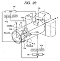
- FIG. 23 is a view showing an outline of an image stabilization apparatus included in the conventional camera.
- a shake which occurs to the camera has six degrees of freedom in total, which are rotational movements of three degrees of freedom constituted of pitching, yawing and rolling movement, and translation movements of three degrees of freedom constituted of movements in an X-axis, a Y-axis and a Z-axis directions.
- the image stabilization apparatuses which are commercialized at present usually corrects the image blur due to the rotational movements of two degrees of freedom constituted of pitching and yawing movements.
- Movement of camera is monitored by an angular velocity sensor 130.
- a piezoelectric vibration angular velocity sensor that detects a Coriolis force which is caused by rotation is generally used.
- the angular velocity sensor 130 contains three detectors which perform detection of pitching movement that is the rotation around the Z-axis in FIG. 23 , detection of yawing movement that is the rotation around the Y-axis in FIG. 23 , and detection of rolling movement that is the rotation around the X-axis (optical axis) in FIG. 23 .
- output of the angular velocity sensor 130 is sent to a lens CPU 106, and a target drive position of a correcting lens 101 for image stabilization is calculated.
- instruction signals are sent to voltage drivers 161x and 161y, and the voltage drivers 161x and 161y follow the instruction signals, and drive lens drivers 120x and 120y.
- the position of the correcting lens 101 is monitored by lens position detectors 110x and 110y, and is fed back to the lens CPU 106.
- the lens CPU 106 performs positional control of the correcting lens 101 based on the target drive position and the position of the correcting lens 101.
- image stabilization apparatus detection of movement of camera due to shake is performed by only the angular velocity sensor 130, and therefore, the angular movement (rotational movement) can be monitored, but movement which causes the optical axis to move parallel vertically or laterally (hereinafter, referred to as parallel movement) cannot be monitored. Accordingly, image stabilization can be performed only for the movements of the two degrees of freedom constituted of pitching and yawing movements.
- the case of performing shooting by using a micro lens with a focal length of 100 mm will be described as an example.
- the angular velocity sensor output substantially 0.8 deg/s
- the shooting magnification ⁇ is substantially zero.
- the shooting magnification is very large, and the influence of parallel movement cannot be ignored.
- the movement width in the image plane at the time of performing shooting with an exposure time of 1/15 second becomes 67 ⁇ m, and the image blur due to parallel movement cannot be ignored.
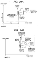
- the first one is the model expressing a parallel movement and a rotational movement (see FIGS. 24A and 24B ).
- the position of the object can be determined if defining the three degrees of freedom: a position X(t) in the X-axis direction; a position Y(t) in the Y-axis direction; and the rotational angle ⁇ (t) of the object itself are specified as shown in FIG. 24A .
- the movement of the object can be expressed by three components of an X-axis direction translation velocity Vx(t) and a Y-axis direction translation velocity Vy(t) of a reference point (principal point 02) set on the object, and a rotation angular velocity ⁇ ( t ) around the reference point on the object as shown in FIG. 24B .
- This model is the commonest .
- the second one is the model expressing an instantaneous center of rotation and a rotation radius (see FIG. 25 ).
- the movement within the plane can be expressed by a locus f(t) of the instantaneous center of rotation and the rotation velocity ⁇ ( t ) at the instant.
- This model is often used in the analysis of a link mechanism in mechanics.
- Japanese Patent Application Laid-Open No. 2004-295027 uses the concept of an instantaneous center which is frequently used in the mechanics, as the model expressing the movement in the space. This is the idea that the movement in the space can be expressed by a succession of the rotational movement, that is, the movement in the space is a rotational movement with a certain radius with a certain point as the center at the instant, and is the rotational movement of the radius with the next certain point as the center at the next instant. Therefore, it can be said that in Japanese Patent Application Laid-Open No. 2004-295027 , the movement of camera due to shake is modeled as a succession of the rotational movement having the instantaous center.
- the present invention is made in view of the aforementioned problems, and has an object to provide an image stabilization apparatus and an image pickup apparatus which enable accurate image stabilization without a control failure, reduces a calculation amount, and can minimize an error amount accompanying a change in principal point position of a shooting optical system, in whatever state an angular movement and a parallel movement coexist.
- an image stabilization apparatus as defined in claim 1. Furthermore, there is provided an image pickup apparatus as defined in claim 14.
- the shake movement of the camera held by human hands, and an image movement which occurs on an image plane as a result of the shake movement of the camera will be expressed by "rotation revolution movement expression” with the movement model expressed by a rotation movement and a revolution movement and a geometrical-optical expression being combined.
- the present embodiment is an image stabilization apparatus which calculates a camera movement from the measured values of an accelerometer and an angular velocity sensor, and the rotation revolution movement expression, and further calculates an image movement. By performing drive control of a part or whole of the shooting lens or a part or whole of the image pickup device based on a calculated value of the image movement, the image blur is corrected.
- the present invention provides an image stabilization apparatus which corrects an image blur by performing image processing of a shot image based on the calculated value of the image movement obtained from the rotation revolution movement expression.
- FIG. 1 is a block diagram illustrating a main part of an image pickup apparatus (camera system) including an image stabilization apparatus according to embodiment 1 of the present invention.
- the parts which performs the same functions as in the prior art are assigned with the same reference numerals and characters, and the redundant descriptions will be properly omitted.
- An image stabilization apparatus is provided in a lens-barrel 102 attachable to and detachable from a camera body 201, and performs blur correction with respect to the directions of five degrees of freedom of pitching (rotation around an Z 2 -axis), yawing (rotation around Y 2 -axis), an Y 2 -axis direction, a Z 2 -axis direction and an X 2 -axis (optical axis) direction.
- degrees of freedom of pitching rotation around an Z 2 -axis
- yawing rotation around Y 2 -axis
- an Y 2 -axis direction a Z 2 -axis direction
- X 2 -axis optical -axis
- an image stabilization system in the pitching rotation and the Y 2 -axis direction, and an optical axis direction image stabilization system in the X 2 -axis (optical axis) direction are shown, and an image stabilization system in the yawing rotation and the Z 2 -axis direction is the same as the image stabilization system of the pitching rotation and the Y 2 -axis direction.
- An angular velocity sensor 130 is an angular velocity detector which is floatingly supported with respect to the lens barrel 102, and detects the angular velocity of the movement which occurs to the camera body 201 (lens barrel 102).
- the angular velocity sensor 130 according to the embodiment 1 is a piezoelectric vibration angular velocity sensor that detects Coriolis force which is generated by rotation.
- the angular velocity sensor 130 is an angular velocity sensor internally having sensitivity axes for three axis rotation of pitching, yawing and rolling. The reason why the angular velocity sensor 130 is floatingly supported is to eliminate the influence of mechanical vibration accompanying the mechanism operation of the camera as much as possible.
- the angular velocity sensor 130 outputs an angular velocity signal corresponding to a detected angular velocity to a filter 160c.
- An accelerometer 121 is an acceleration detector that detects the acceleration of the movement which occurs to the camera body 201 (lens barrel 102).
- the accelerometer 121 according to the embodiment 1 is a triaxial accelerometer having three sensitivity axes with respect to the three directions of the X-axis, Y-axis and Z-axis, and is floatingly supported by the lens barrel 102.
- the accelerometer 121 is floatingly supported for the same reason as the case of the angular velocity sensor 130.
- the accelerometer 121 is a triaxial acceleration sensor (acceleration sensor using a weight) in the present embodiment, and the frequency characteristics of two axes are equally high, but the characteristic of the remaining one axis is low.
- the two axes with high sensitivity are used, and the one axis low in characteristic is aligned with the X 2 -axis (optical axis direction). This is for precisely detecting the accelerations in the Y 2 -axis direction and the Z 2 -axis direction which have a large influence on image blur correction.
- the output of the accelerometer 121 is A/D-converted after passing through a low pass filter (LPF) such as a filter 160a or the like, and is input to an IS (image stabilizing) lens correction calculator 107 in a lens CPU 106.
- LPF low pass filter
- the accelerometer 121 may be mounted to a movable mirror frame which moves in the optical axis direction during zooming or the like, a frame that holds the other optical system, or a unit in an optical system such as a stop, but in such a case, it is necessary to enable the position of the accelerometer 121 with respect to the principal point position after zooming to be detected.
- the angular velocity sensor 130 is of a vibratory gyro type as described above, and vibrates at 26 KHz. Accordingly, if these sensors are mounted on the same substrate, the accelerometer 121 is likely to pick up the vibration noise, and therefore, the accelerometer 121 and angular velocity sensor 130 are mounted on separate substrates.
- An image stabilizing lens driver 120 is a driver (actuator) which generates a drive force for driving a correcting lens 101 for correction of the image blur within the plane (within the Y 2 Z 2 plane) perpendicular to an optical axis I.
- the image stabilizing lens driver 120 generates a drive force in the Y 2 -axis direction, and drives the correcting lens 101 when a coil not illustrated is brought into an energized state by the drive current output by a voltage driver 161.
- a lens position detector 110 is an optical position detector which detects the position of the correcting lens 101 in the plane orthogonal to the optical axis I.
- the lens position detector 110 monitors the present position of the correcting lens 101, and feeds back the information concerning the present position of the correcting lens 101 to an image stabilizing controller 108 via an A/D converter.
- the lens CPU 106 is a central processor that performs various controls of the lens barrel 102 side.
- the lens CPU 106 calculates the focal length based on the pulse signal output by a focal length detector 163, and calculates an object distance based on the pulse signal output by an object distance detector 164.
- the image stabilizing lens correction calculator 107, the image stabilizing controller 108 and an autofocus lens controller 401 are provided in the lens CPU 106.
- the lens CPU 106 can perform communication with a body CPU 109 via a lens junction 190 provided between the lens barrel 102 and the camera body 201.
- An image blur correction start command is sent from the body CPU 109 synchronously with half depression ON of a release switch 191 and an image blur correction stop command is sent to the CPU 106 synchronously with half depression OFF.
- the lens CPU 106 monitors the state of a blur correction switch (SW) 103 provided in the lens barrel 102. If the blur correction switch 103 is ON, the lens CPU 106 performs image blur correction control, and if the blur correction switch 103 is OFF, the lens CPU 106 ignores the image blur correction start command from the body CPU 109 and does not perform blur correction.
- SW blur correction switch
- the image stabilizing lens correction calculator 107 is a part which converts the output signals of the filters 160a and 160c into the target velocity information for driving the lens barrel 102 to the target position.
- the image stabilizing controller 108, the filters 160a and 160c, an EEPROM 162, the focal length detector 163, and the object distance detector 164 are connected to the image stabilizing lens correction calculator 107.
- the autofocus lens controller 401 has an optical axis direction movement velocity calculator 402 which performs calculation for performing optical axis direction movement correction by using the accelerometer output value from the image stabilizing lens correction calculator 107, and outputs the calculation result to an autofocus lens voltage driver 172.
- An autofocus lens 140 can be driven in the optical axis direction by an autofocus lens driver 141 using an ultrasonic motor or a stepping motor as a drive source.
- the autofocus lens voltage driver 172 generates a voltage for performing drive control of the autofocus lens driver 141.
- the image stabilizing lens correction calculator 107 captures the output signals (analog signals) output from the angular velocity sensor 130 and the accelerometer 121 through the filters 160a and 160c by quantizing the signals by A/D conversion. Based on the focal length information obtained from the focal length detector 163, the object distance information obtained from the object distance detector 164 and the information peculiar to the lens which is written in the EEPROM 162, the image stabilizing lens correction calculator 107 converts the signals into the target drive velocity of the correcting lens 101. The conversion method (calculating method) to the target drive position performed by the image stabilizing lens correction calculator 107 will be described in detail later.
- the target velocity signal which is the information of the target drive velocity calculated by the image stabilizing lens correction calculator 107 is output to the image stabilizing controller 108.
- the image stabilizing controller 108 is the part which controls the image stabilizing lens driver 120 via the voltage driver 161, and performs follow-up control so that the correcting lens 101 is driven as the information of the target drive velocity.
- the image stabilizing controller 108 converts the position detection signal (analog signal) output by the lens position detector 110 into a digital signal and captures the digital signal.
- the input part to the image stabilizing controller 108 is for the target velocity signal converted into the target drive velocity of the correcting lens 101 which is the output of the image stabilizing lens correction calculator 107, and another input part is for the positional information of the correcting lens 101 which is obtained by the lens position detector 110.
- velocity control is performed by using the deviation between the target drive velocity of the correcting lens 101 and the actual velocity information.
- the image stabilizing controller 108 calculates a drive signal based on the target drive velocity, velocity information of the correcting lens 101 and the like, and outputs the digital drive signal to the voltage driver 161.
- PID control is performed by using the deviation of the target positional information and the lens positional information of the correcting lens 101.
- the image stabilizing controller 108 calculates the drive signal based on the target positional information, the positional information of the correcting lens 101 and the like, and outputs the digital drive signal to the voltage driver 161.
- the filters 160a and 160c are filters which remove predetermined frequency components from the output signals of the angular velocity sensor 130 and the accelerometer 121, and cut the noise component and the DC component included in the high-frequency band.
- the filters 160a and 160c perform A/D conversion of the angular velocity signals after the predetermined frequency components are removed, and thereafter, output the angular velocity signals to the image stabilizing lens correction calculator 107.
- the voltage driver 161 is a driver which supplies power to the image stabilizing driver 120 according to the input drive signal (drive voltage).
- the voltage driver 161 performs switching for the drive signal, applies a voltage to the image stabilizing lens driver 120 to drive the image stabilizing lens driver 120.
- the EEPROM 162 is a nonvolatile memory which stores lens data that is various kinds of unique information concerning the lens barrel 102, the coefficients for converting the pulse signals output by the object distance detector 164 into physical quantities.
- the focal length detector 163 is a zoom encoder which detects a focal length.
- the focal length detector 163 outputs the pulse signal corresponding to a focal length value to the image stabilizing lens correction calculator 107.
- the object distance detector 164 is a focusing encoder for detecting the distance to an object.
- the object distance detector 164 detects the position of a shooting optical system 105 (autofocus lens 140), and outputs the pulse signal corresponding to the position to the image stabilizing lens correction calculator 107.
- the position of the principal point A of the shooting optical system 105 is calculated as will be described later.
- the positional information of the principal point A of the shooting optical system 105 stored in the EEPROM 162 is read, and control which will be described later is performed.
- the body CPU 109 is a central processor which performs various controls of the entire camera system.
- the body CPU 109 transmits a blur correction start command to the lens CPU 106 based on the ON operation of the release switch 191.
- the body CPU 109 transmits a blur correction stop command to the lens CPU 106 based on the OFF operation of the release switch 191.
- various kinds of processing are performed other than them.
- Information on the release switch 191 is input to the body CPU 109, and the release switch 191 can detect half depressing or fully depressing operation of the release button not illustrated.
- the release switch 191 is a switch which detects the half depressing operation of the release button not illustrated, starts a series of shooting preparing operations, detects a fully depressing operation of the release button and starts a shooting operation.
- a rotation angular velocity calculator 301 calculates a rotation angular velocity ⁇ caxy based on the angular velocity sensor output value.
- the angular velocity sensor output value and the rotation angular velocity are generally in the linear relation, and therefore, the rotation angular velocity can be obtained by multiplying the angular velocity sensor output value by a coefficient.
- a high-pass filter 303 is a filter which transmits a frequency component necessary for blur correction.
- a revolution angular velocity calculator 304 can obtain a revolution angular acceleration ⁇ axy by dividing a revolution acceleration component jr axy ⁇ axy which is the input value from the high-pass filter 303 by an object side focal length r axy . Further, by performing time integration of the revolution angular acceleration, a revolution angular velocity ⁇ axy required for control is obtained.
- a rotation revolution difference image stabilization amount calculator 305 calculates the image movement velocity in the Y 2 direction of the image pickup surface of the image pickup device 203 by substituting a read imaging magnification: ⁇ , an actual focal length value: f, and the rotation angular velocity ⁇ caxy and the revolution angular velocity ⁇ axy ,which are calculated in real time, into the following Expression (15)which will be described later.
- the obtained image movement velocity becomes a target drive velocity.
- the image movement velocity in the Z 2 direction of the image pickup surface can be similarly obtained from expression (16) which will be described later, but the description will be omitted here.
- a theoretical formula selector 306 selects whether the formula of rotation revolution difference movement correction using a difference between the rotation angular velocity and the revolution angular velocity, or the formula of rotation movement correction using only a rotation angular velocity as the formula used for correction calculation according to the ratio of the revolution angular velocity to the rotation angular velocity.
- V dcxy ( O 2 -X 2 Y 2 ) represents an image movement velocity vector in an image pickup surface
- ⁇ represents an imaging magnification [(without unit)] at the time of image blur correction of the shooting lens of this camera
- f represents an actual focal length [mm] at the time of image blur correction of the shooting lens of this camera
- (1+ ⁇ )f represents an image side focal length [mm]
- ⁇ caxy represents time derivative value of the rotation angle ⁇ caxy with the principal point A as the center
- ⁇ axy represents time derivative value of revolution angle ⁇ axy with an origin O as the center
- e j ( ⁇ /2) represents that the image movement velocity vector indicates
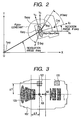
- FIG. 2 shows a schematic diagram of a state of a camera which is projected on an XY plane.
- the outer shape and the lens of the camera are illustrated.
- a principal point A xy of the optical system In the camera, a principal point A xy of the optical system, an accelerometer B xy , a center C xy of the image pickup device 203 are illustrated.
- An origin O 4 of the coordinate system O 4 -X 4 Y 4 is fixed to a principal point A xy of the optical system.
- an X 4 -axis keeps a parallel state with respect to the X-axis
- a Y 4 -axis keeps the parallel state with respect to a Y-axis.
- An origin O 2 of a coordinate system O 2 -X 2 Y 2 is fixed to the principal point A xy , and moves integrally with the camera.
- the X 2 -axis is always matched with the optical axis of this camera.
- the angle around the origin O 2 from the X 4 -axis to the X 2 -axis is set as the rotation angle ⁇ caxy .
- the angle around the origin O from the X-axis to a scalar r axy is set as a revolution angle ⁇ axy .
- Scalar r axy ⁇ (1+ ⁇ )f/ ⁇ represents an object side focal length.
- ⁇ is an imaging magnification.
- a gravity acceleration vector G xy at the principal point A xy has an angle ⁇ gxy around the principal point A xy from the X 4 -axis to the vector G xy by normal rotation (counterclockwise).
- the ⁇ gxy is a constant value.
- the approximate expression means that the image movement velocity in the Y 2 direction in the image pickup surface can be expressed by -(image side focal length) x (value obtained by subtracting the revolution angular velocity from the rotation angular velocity).
- the exact formula without approximation is expression (12).
- the exact formula expression (12) may be used.
- r axy ⁇ (1+ ⁇ )f/ ⁇ represents the object side focal length.
- V ⁇ dcxy ⁇ O 2 - X 2 ⁇ Y 2 f ⁇ r ⁇ axy r axy - f - f ⁇ r axy ⁇ r ⁇ axy r axy - f 2 ⁇ e j ⁇ ⁇ axy - ⁇ caxy + f ⁇ r ⁇ axy r axy - f ⁇ ⁇ ⁇ axy ⁇ e j ⁇ ⁇ axy + / 2 ⁇ - ⁇ caxy - 1 + ⁇ ⁇ f ⁇ ⁇ ⁇ caxy ⁇ e j / 2 ⁇
- the components of the yawing angle movement of the camera shake on the ZX plane and the parallel movement in the Z 2 -direction are expressed by the rotation revolution movement formula, and the Z 2 direction image movement (image movement in the lateral
- the accelerometer output A ccy2(O-X2Y2) in the Y 2 -axis direction, which is used for obtaining the revolution angular velocity ⁇ axy is represented by expression (27).
- a ccy 2 ⁇ O - X 2 ⁇ Y 2 ⁇ r axy ⁇ ⁇ ... axy third term acceleration of revolution + j ⁇ 2 ⁇ r axy ⁇ ⁇ ⁇ axy fourth term : Coriolis force + j ⁇ r baxy ⁇ ⁇ ⁇ caxy 2 ⁇ sin ⁇ baxy + ⁇ fifth term : centripetal force of rotation + j ⁇ r baxy ⁇ ⁇ ⁇ caxy 2 ⁇ sin ⁇ baxy + / 2 ⁇ sixth term : acceleration of rotation + jG ⁇ sin ⁇ gxy - ⁇ seventh term : gravity acceleration component
- the third term jr axy ⁇ axy in expression (27) is the component required for obtaining the revolution angular velocity ⁇ axy which is desired to be obtained in embodiment 1, and if the third term is divided by the known r axy , and is integrated,
- the fourth term, the fifth term, the sixth term and the seventh term are unrequired terms for calculation, and unless they are erased, they become the error components at the time of obtaining the revolution angular velocity ⁇ axy .
- the fourth term j 2 ⁇ axy ⁇ axy represents Coriolis force, and if the movement in the camera optical axis direction is small, the velocity in the optical axis direction ⁇ axy ⁇ 0, the fourth term is the term which can be ignored. Expression (27) will be also described later.
- the fifth term and the sixth term are error components which are included in the accelerometer output A ccy2(O-x2y2) since the accelerometer 121 cannot be disposed in the ideal principal point position A, and is disposed in the position B.
- the fifth term jr baxy ⁇ 2 caxy sin( ⁇ baxy + ⁇ ) is the centripetal force which is generated due to the rotation of the accelerometer 121 around the principal point A.
- r baxy and ⁇ baxy represent the coordinates of the position B where the accelerometer 121 is mounted, and are known.
- ⁇ caxy is a rotation angular velocity, and is the value which can be measured by the angular velocity sensor 130 mounted to the camera. Therefore, the value of the fifth term can be calculated.
- the sixth term jr baxy ⁇ caxy sin( ⁇ baxy + ⁇ / 2 ) is the acceleration component when the accelerometer 121 rotates around the principal point A, and r baxy and ⁇ baxy represent the coordinates of the position B where the accelerometer 121 is mounted, and are known.
- ⁇ caxy can be calculated by differentiating the value of the angular velocity sensor 130 mounted to the camera. Therefore, the value of the sixth term can be calculated.
- the seventh term jG sin( ⁇ gry - ⁇ ) is the influence of the gravity acceleration, and can be treated as the constant in this approximate expression, and therefore, can be eliminated by the filtering processing of a circuit.
- the accelerometer output A ccx2(O-X2Y2) in the X 2 -axis direction that is an optical axis for use in optical axis direction movement correction is represented by expression (26).
- what is required for optical axis direction movement correction is only the first term r ⁇ axy (acceleration in
- the second term, the fifth term, the sixth term and the seventh term are the components unrequired for the optical axis direction movement correction, and unless they are erased, they become error components at the time of obtaining the acceleration r ⁇ axy in the X 2 -axis direction which is the optical axis.
- the second term, the fifth term, the sixth term and the seventh term can be deleted by the similar method to the case of expression (27). Expression (26) will also be described later.
- the error components included in the output of the accelerometer 121 can be erased, but if the correction calculation is performed, blur correction operation start is delayed by the calculation time, and accurate blur correction cannot be made.
- the accelerometer 121 is placed in the lens barrel 102, and thereby, the error component included in the output of the accelerometer 121 can be minimized. Therefore, the correction calculating time is not required, and thereby, accurate blur correction can be made.
- FIG. 3 is a sectional view of the lens barrel 102, and is for describing the arrangement of the shooting optical system 105, the accelerometer 121 and the angular velocity sensor 131.
- the principal point moves on the optical axis I within the range of the point (first point) at which the shooting magnification ⁇ becomes 1.0 and the second point which is the principal point position at which the shooting magnification ⁇ becomes 0.0 in the shooting optical system.
- the angular velocity sensor 131 is placed at an arbitrary position of the lens barrel 102, but the accelerometer 121 is placed at the position in the optical axis I direction between the principal point position A1 (first point) at the time of equal-magnification shooting and the principal point position A2 (second point) at the time of infinity shooting.
- the accelerometer 121 is placed at the position in the optical axis direction, where the shooting magnification ⁇ becomes 0.5.
- the position in the optical axis I direction of the accelerometer 121 is set as a principal point position A3, the distance in the optical axis I direction from the principal point position A1 at the time of equal-magnification shooting is set as ⁇ X, and the distance in the direction perpendicular to the optical axis I is set as ⁇ Y.
- the sum of the fifth term and the sixth term which are the unrequired terms in expression (27) is expressed as an accelerometer position error function g( ⁇ ba ) as follows.
- g ⁇ ba j ⁇ r baxy ⁇ ⁇ ⁇ baxy 2 ⁇ sin ⁇ baxy + ⁇ + j ⁇ r baxy ⁇ ⁇ ⁇ caxy ⁇ sin ⁇ baxy + / ⁇ 2
- the fourth term in expression (27) can be ignored, and the seventh term also can be eliminated by filtering processing of a circuit.
- the outputs of the accelerometer 121 after the filtering processing are the third term, the fifth term and the sixth term, and therefore, when the ratio of the accelerometer position error function g( ⁇ ba ) included in the output of the accelerometer 121 and represented by expression (30) is set as an error ratio function f( ⁇ ba ), the error ratio function f( ⁇ ba ) can be expressed as follows.
- f ⁇ ba r baxy ⁇ ⁇ ⁇ baxy 2 ⁇ sin ⁇ baxy + ⁇ + r baxy ⁇ ⁇ ⁇ sin ⁇ baxy + / ⁇ 2 r baxy ⁇ ⁇ ⁇ axy + r baxy ⁇ ⁇ ⁇ caxy 2 ⁇ sin ⁇ baxy + ⁇ + r baxy ⁇ ⁇ ⁇ caxy ⁇ sin ⁇ baxy + / ⁇ 2
- f ⁇ ba r baxy ⁇ ⁇ ⁇ caxy 2 ⁇ sin ⁇ baxy + ⁇ + r baxy ⁇ ⁇ ⁇ sin ⁇ baxy + / ⁇ 2
- the error ratio function f( ⁇ ba ) shown in expression (32) is as follows when the values of ⁇ caxy and ⁇ caxy are substituted.
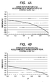
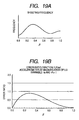
- FIG. 4A illustrates the error ratio in each imaging magnification which is obtained by obtaining the focal length f of the shooting optical system 105 and the imaging magnification at the time, in Expression (33).
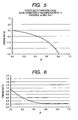
- FIG. 4B and FIG. 5 illustrate the error ratios at the time of disposing the accelerometer 121 at the equal-magnification position and the infinity position, for example.
- FIG. 6 illustrates how the result of sum of products of the values at the respective imaging magnifications of the error ratios obtained as illustrated in FIGS. 4A, 4B and 5 changes when the accelerometer 121 is disposed at the respective shooting magnifications. As illustrated in FIG.
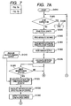
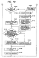
- FIGS. 7A and 7B are flowcharts illustrating the flow of the operation relating to the image stabilizing lens correction of the image stabilization apparatus in embodiment 1.
- the operation relating to the correction amount calculation of the correcting lens 101 will be described according to FIGS. 7A and 7B .
- step (hereinafter, described as S) 1010 when the blur correction SW 103 is in an ON state, a correction start command is output from the camera body 201 by half depression ON of the release switch 191. By receiving the correction start command, the blur correction operation is started.
- S1020 it is determined whether or not a blur correction stop command is output from the camera body 201, and when it is output, the flow proceeds to S1400, and the blur correcting operation is stopped. When it is not output, the flow proceeds to S1030 to continue the blur correction operation. Accordingly, the blur correction operation is continued until a blur correction stop command is output from the camera body 201.
- the numeric value obtained from the focal length detector 163 is read.
- the numeric value of the focal length detector 163 is used for calculation of the imaging magnification ⁇ .
- the numeric value (absolute distance) obtained from the object distance detector 164 is read.
- the imaging magnification ⁇ is calculated based on the numeric value of the focal length detector 163 and the numeric value of the object distance detector 164.
- Calculation of the imaging magnification ⁇ is a unique formula depending on the optical system configuration, and is calculated based on the imaging magnification calculation formula. The obtaining of the imaging magnification ⁇ does not especially have to be performed based on the formula, but the imaging magnification may be obtained from a table with respect to the encoder position of the focal length and the absolute distance.
- the outputs of the angular velocity sensor 130 and the accelerometer 121 are read.
- the rotation angular velocity ⁇ caxy is calculated based on the angular velocity sensor output value from S1310.
- the angular velocity sensor output value and the rotation angular velocity are generally in the linear relation, and therefore, the rotation angular velocity can be obtained by multiplication by a coefficient.
- S1410 it is determined whether the release switch 191 is fully depressed to be ON, that is, whether the release button not illustrated is fully depressed. If YES, that is, if it is the exposure time of the camera, the flow proceeds to S1420, and if NO, that is, if it is before exposure, the flow proceeds to S1090. In S1090, filtering processing is performed for the accelerometer output value A ccy2(O-X2Y2) from S1080, and the seventh term of expression (27) is erased. The value after the elimination is set as A' ccy2(O-X2Y2) .
- the output value of S1090: A' ccy2(O-X2Y2) is divided by the object side focal length r axy , and thereby, the revolution angular acceleration ⁇ axy is obtained. Further, by performing time integration of the revolution angular acceleration, the revolution angular velocity ⁇ axy necessary for control is obtained.
- the ratio of the revolution angular velocity to the rotation angular velocity obtained in S1070 is calculated.
- the value of the rotation revolution angular velocity ratio calculated in S1104 is stored. When the previous value remains, the new one is written over the previous value and is stored, and the flow proceeds to S1110.
- S1420 the value of the rotation revolution angular velocity ratio stored in S1106 in the past is read, and the flow proceeds to S1110.
- S1110 it is determined whether or not the ratio of the rotation angular velocity ⁇ caxy from S1070 and the revolution angular velocity ⁇ axy from S1100 is larger than 0.1 (larger than the predetermined value). When the ratio is larger than 0.1, the flow proceeds to S1120. When the ratio is 0.1 or less (the predetermined value or less), the flow proceeds to S1130.
- the image movement velocity in Y 2 direction of the image pickup surface is calculated by substituting the read imaging magnification ⁇ , the actual focal length value f, the rotation angular velocity value ⁇ caxy calculated in real time, and the estimated revolution angular velocity ⁇ axy obtained by multiplying the rotation revolution angular velocity ratio stored in S1106 by the rotation angular velocity value ⁇ caxy calculated in real time into expression (15).
- follow-up control calculation for driving the correcting lens 101 is performed, with considering the sensitivity of the correcting lens 101, based on the image movement velocity obtained by the rotation revolution difference movement correction calculation (S1120) or the rotation movement correction calculation (S1130). At this time, the present position output of the correcting lens 101 is simultaneously monitored.
- the calculation result is output to the voltage driver 161 which drives the correcting lens 101 based on the follow-up control calculation result in S1140. After the calculation result is output to the voltage driver 161, the flow returns to S1020.
- S1300 it is determined whether or not the imaging magnification ⁇ is 0.15 or more. When the imaging magnification ⁇ is 0.15 or more, the flow proceeds to S1320. When the imaging magnification ⁇ is less than 0.15 in S1300, the flow proceeds to S1410.
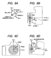
- a moving coordinate system O 2 -X 2 Y 2 Z 2 which is fixed to the camera will be described.
- the coordinate system O 2 -X 2 Y 2 Z 2 performs shake movement integrally with the camera, and therefore, the coordinate system is called a moving coordinate system.
- a three-dimensional coordinate system will be described with a three-dimensional coordinate system diagram of FIG. 8A .
- the coordinate system is an orthogonal coordinate system, and as in FIG. 8A , the X 2 -axis, Y 2 -axis and Z 2 -axis are orthogonal to one another.
- Pitching is defined as the rotation about the Z 2 -axis around the origin O 2 and the pitching from the +X 2 -axis to the +Y 2 -axis is assigned with plus sign with the origin O 2 as the center.
- Yawing is defined as the rotation about the Y 2 -axis around the origin O 2 and the yawing from the +Z 2 -axis to the +X 2 -axis is assigned with plus sign.
- Rolling is defined as the rotation about the X 2 -axis around the origin O 2 and the rolling from the +Y 2 -axis to the +Z 2 -axis is assigned with plus sign.
- FIG. 8D is a camera side view with the camera sectional view of FIG. 1 being simplified, and the lens is illustrated in the see-through state.
- the coordinate system O 2 -X 2 Y 2 Z 2 which is fixed to the camera will be described.
- the origin O 2 of the coordinate system is fixed to the principal point A of the entire optical system (shooting optical system 105) which exists in the lens barrel 102, and the image pickup device direction on the optical axis is set as the plus direction of X 2 -axis.
- the camera upper direction (upper direction of this drawing) is set as the plus direction of Y 2 -axis, and the remaining direction is set as the plus Z 2 axis.
- a position B of the accelerometer 121 is expressed by a line segment length r baxy between the origin O 2 and the position B of the accelerometer 121, and an angle ⁇ baxy formed by the X 2 -axis and the line segment r baxy .
- the rotational direction in the direction to the plus Y 2 -axis from the plus X 2 -axis with the O 2 -axis as the center is set as plus direction.
- the camera top view of FIG. 8B illustrates the position B of the accelerometer 121 in the state projected onto a Z 2 X 2 plane.
- the position B of the accelerometer 121 is expressed by a line segment r apelx between the origin O 2 and the position B of the accelerometer 121 and an angle ⁇ apelx formed by the Z 2 -axis and the line segment r chilix .
- the rotational direction in the direction to +X 2 -axis from the +Z 2 -axis is set as plus direction.
- the position B is also expressed by an angle ⁇ apelx formed by the X 2 -axis and the line segment r chilix .
- the rotational direction in the direction to the +Z 2 -axis from the +X 2 -axis is set as plus direction.
- the camera front view of FIG. 8C illustrates the position of the accelerometer 121 in the state projected on a Y 2 Z 2 plane.
- the position B of the accelerometer 121 is expressed by a line segment length r bayz between the origin O 2 and the position B of the accelerometer 121, and an angle ⁇ bayz formed between the Y 2 -axis and the line segment r bayz .
- the rotational direction in the direction of the +Z 2 -axis from the +Y 2 -axis with the O 2 -axis as the center is set as plus direction.
- the coordinate system O 9 -X 9 Y 9 Z 9 is integral with the object, and therefore, will be called a fixed coordinate system.
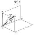
- FIG. 9 is a diagram expressing only the optical system of the camera in a three-dimensional space.
- a coordinate origin O 9 is matched with the subject to be shot.
- a coordinate axis +Y 9 is set in the direction opposite to the gravity acceleration direction of the earth. Remaining coordinate axes +X 9 and +Z 9 are arbitrarily disposed.
- a point D is an imaging point of the object S, and is geometric-optically present on the extension of a line segment OA.
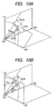
- FIG. 10A a three-dimensional expression method of the principal point A in the fixed coordinate system O 9 -X 9 Y 9 Z 9 will be described. Since the position of the camera is illustrated on the space, only the principal point A to be the reference is illustrated in FIG. 10A , and the other portions such as the imaging point D and the like are not illustrated.
- the principal point A is shown by the vector with the origin O 9 as the reference, and is set as R a .
- the length of the R a is set as a scalar r a .
- An angle to the R a from the Z 9 -axis with O 9 as the center is set as ⁇ a .
- An angle from the X 9 -axis from a straight line OJ which is the line of intersection between a plane including the R a and the Z 9 -axis and the XY plane, is set as ⁇ a .
- R a can be expressed in the polar coordinate system by three values of the scalar r a , the angle ⁇ a , and the angle ⁇ a . If the three values can be calculated from measurement by a sensor and the like, the position of the principal point A of the camera is obtained.
- the formula for transforming the position of the principal point A into an orthogonal coordinate system from a polar coordinate system is the following formula.
- FIG. 10B the orthogonal coordinate system is illustrated.
- X a r a ⁇ sin ⁇ a ⁇ cos ⁇ a
- Y a r a ⁇ sin ⁇ a ⁇ sin ⁇ a
- Z a r a ⁇ cos ⁇ a
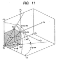
- FIG. 11 a moving coordinate system O 4 -X 4 Y 4 Z 4 will be described.
- the moving coordinate system O 4 -X 4 Y 4 Z 4 is also provided to the principal point A.
- An original O 4 is fixed to the principal point A. More specifically, the origin O 4 also moves with movement of the principal point A.
- a coordinate axis +X 4 is always disposed to be parallel with the coordinate axis +X 9
- a coordinate axis +Y 4 is always disposed parallel with the coordinate axis +Y 9 .
- the parallelism is always kept when the principal point A moves.
- the direction of the gravity acceleration G at the principal point A is a minus direction of the coordinate axis Y 9 .
- FIG. 11 Two-dimensional coordinate expression when being projected on the X 9 Y 9 plane will be described.
- the point which is the principal point A projected on the X 9 Y 9 plane is set as a principal point A xy .
- the line segment between the origin O 9 and the principal point A xy is set as the scalar r axy
- the angle to the scalar r axy from the X 9 -axis with the origin O 9 as the center is set as ⁇ axy .
- the angle ⁇ axy is the same angle as ⁇ a described above.
- reference characters xy is assigned.
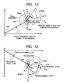
- FIG. 12 illustrates the camera state projected on the X 9 Y 9 plane.
- the origin O 4 of the coordinate system O 4 -X 4 Y 4 is fixed to the principal point A xy which is described above.
- the X 4 -axis keeps a parallel state with the X 9 -axis
- the Y 4 -axis keeps a parallel state with the Y 9 -axis.
- the origin O 2 of the coordinate system O 2 -X 2 Y 2 is fixed to the principal point A xy , and moves integrally with the camera.
- the X 2 -axis is always matched with the optical axis of this camera.
- the gravity acceleration G xy at the principal point A xy is in the positive rotation (counterclockwise) from the X 4 -axis with the principal point A xy as the center, and the angle to G xy is set as ⁇ gxy .
- the ⁇ gxy is a constant value.
- the origin O 9 where the object is present is compared to the sun, and the principal point A of the camera is compared to the center of the earth.
- the angle ⁇ axy is called “the revolution angle” within the XY plane
- the angle ⁇ caxy is called “the rotation angle” within the XY plane. More specifically, this is similar to the fact that revolution indicates that the earth (camera) goes around the sun (object), whereas rotation indicates the earth (camera) itself rotates.
- FIG. 13 illustrates the camera state projected onto the Z 9 X 9 plane.
- the origin O 4 of the coordinate system O 4 -Z 4 X 4 is fixed to the principal point A zx .
- the Z 4 -axis keeps a parallel state with the Z 9 -axis
- the X 4 -axis keeps a parallel state with the X 9 -axis.
- the origin O 2 of the coordinate system O 2 -Z 2 X 2 is fixed to the principal point A zx , and moves integrally with the camera.
- the X 2 -axis is always matched with the optical axis of the camera.
- the angle at the time of being rotated to the X 2 -axis from the Z 4 -axis with the origin O 2 as the center is set as ⁇ malariax . Further, the angle at the time of being rotated to the X 2 -axis from the X 4 -axis with the origin O 2 as the center is set as ⁇ malariax .
- the gravity acceleration G at the position of the principal point A is in the minus direction of the coordinate axis Y 9 .
- the line segment connecting the object S and the principal point A is set as a Ra , and may be modeled.
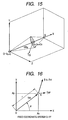
- a new fixed coordinate system O-XYZ is set.
- the origin O of the fixed coordinate system O-XYZ is caused to correspond to the origin O 9
- the coordinate axis X is caused to correspond to the optical axis of the camera.
- the direction of the coordinate axis Y is set so that the coordinate axis Y 9 is present within the XY plane. If the coordinate axis X and the coordinate axis Y are set, the coordinate axis Z is uniquely set.
- the fixed coordinate system O 9 -X 9 Y 9 Z 9 will not be illustrated, and only the fixed coordinate system O-XYZ will be illustrated as the fixed coordinate system hereinafter.
- the gravity acceleration G is present within the XY plane.
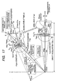
- FIG. 16 is a basic explanatory diagram of a polar coordinate system, the meaning of the codes in the mathematical expression which is common and used here will be described.
- the positional expression of the point A which is present on the coordinate system O-XY is shown by a position R .
- the position R is the function of a time, and can be also described as R ( t ).
- the acceleration R ⁇ is obtained by the first order derivative of the velocity ⁇ by the time t.
- Acceleration vector: R ⁇ r ⁇ ⁇ e j ⁇ + r ⁇ ⁇ ⁇ 2 ⁇ e j ⁇ ⁇ + ⁇ + r ⁇ ⁇ ⁇ ⁇ e j ⁇ ⁇ + / 2 ⁇ + 2 ⁇ r ⁇ ⁇ ⁇ ⁇ ⁇ e j ⁇ ⁇ + / 2 ⁇
- the first term: r ⁇ e j ⁇ represents the acceleration component of a change of the length r
- the second term: r ⁇ 2 e j ( ⁇ + ⁇ ) represents the centripetal force component
- the third term: r ⁇ e j ( ⁇ + ⁇ /2) represents the angular acceleration component
- the fourth term: 2 ⁇ e j ( ⁇ + ⁇ /2) represents the Coriolis force component.
- the acceleration vector is obtained by the following expressions (4a) and (4b).
- a ⁇ x r ⁇ ⁇ cos ⁇ + r ⁇ ⁇ ⁇ 2 ⁇ cos ⁇ + ⁇ + r ⁇ ⁇ ⁇ ⁇ cos ⁇ + / 2 ⁇ + 2 ⁇ r ⁇ ⁇ ⁇ ⁇ cos ⁇ + / 2 ⁇
- a ⁇ y r ⁇ ⁇ sin ⁇ + r ⁇ ⁇ ⁇ 2 ⁇ sin ⁇ + ⁇ + r ⁇ ⁇ ⁇ ⁇ sin ⁇ + / 2 ⁇ + 2 ⁇ r ⁇ ⁇ ⁇ ⁇ sin ⁇ + / 2 ⁇
- the theoretical formula of the present invention will be described in the two-dimensional XY coordinate system when the camera is projected onto the XY plane illustrated in FIG. 17 .
- setting of the coordinate system and codes of the two-dimensional XY coordinate system will be also described. Description will be made by partially including the content which is already described.
- the object S is disposed on the fixed coordinate system O-XY.
- the optical axis of the camera corresponds to the coordinate axis X of the fixed coordinate system O-XY.
- the object S corresponds to the origin O of the fixed coordinate system O-XY.
- the principal point A is expressed by the R axy .
- the line segment length between the origin O and the principal point A of the camera is set as the scalar r axy , and the point where the origin O forms an image by the lens is set as an image forming point D.
- the origin O 4 of the coordinate system O 4 -X 4 Y 4 is fixed to the principal point A, the coordinate axis X 4 is always kept parallel with the coordinate axis X, and the coordinate axis Y 4 is always kept parallel with the coordinate axis Y.
- the origin O 2 of the coordinate system O 2 -X 2 Y 2 is fixed to the principal point A, and the coordinate axis X 2 is always kept in the optical axis direction of the camera.
- the accelerometer 121 is fixed to the point B inside the camera, and is expressed by R baxy in the coordinate system O 2 -X 2 Y 2 .
- the length of a line segment AB is set as the scalar r baxy , and the angle rotated to the line segment AB from the coordinate axis X 2 -axis with the origin O 2 as the center is set as ⁇ baxy .
- the image of the origin O forms an image at the position of a point D differing from the point C of the image pickup device center by the lens.
- the imaging point D with the principal point A as the reference is expressed by R daxy .
- the point D with the point C as the reference is expressed by R dcxy .
- the relative moving velocity vector of the image forming point D with respect to the point C in the moving coordinate system O 2 -X 2 Y 2 at a certain time t2 is set as V dcxy ( O 2 -X 2 Y 2 ).
- the angle formed to the R axy from the coordinate axis X with the origin O as the center is set as a rotation angle ⁇ axy .
- the angle formed from the coordinate axis X 4 to the coordinate axis X 2 with the origin O 4 as the center is set as a revolution angle ⁇ caxy .
- the first order derivative of the R axy by the time t is described as ⁇ axy
- the second order derivative of it is described as R ⁇ axy
- the R caxy is similarly described as ⁇ caxy and R ⁇ caxy
- the R daxy is similarly described as a ⁇ daxy and R ⁇ daxy
- the revolution angle ⁇ axy is similarly described as ⁇ axy and ⁇ axy
- the rotation angle ⁇ caxy is similarly described as ⁇ caxy and ⁇ caxy .
- a relative moving velocity V dcxy ( O 2 -X 2 Y 2) of the imaging point D with the point C as the reference in the moving coordinate system O 2 -X 2 Y 2 is obtained.
- a moving velocity V daxy ( O-XY ) at the imaging point D in the fixed coordinate system O-XY is obtained by the following expression (5).
- V caxy ( O-XY ) of the image pickup device center C in the fixed coordinate system O-XY is obtained by the following expression (6).
- Expression (7) is modified.
- V dcxy ( O-XY ) in the fixed coordinate system O-XY is obtained by the following expression (10).
- V ⁇ dcxy ⁇ O 2 - XY f ⁇ r ⁇ axy ⁇ r axy - f - 1 - f ⁇ r axy ⁇ r ⁇ axy ⁇ r axy - f - 2 ⁇ e j ⁇ ⁇ axy + f ⁇ r axy ⁇ r axy - f - 1 ⁇ ⁇ ⁇ axy ⁇ e j ⁇ ⁇ axy + / 2 ⁇ - 1 + ⁇ ⁇ f ⁇ ⁇ ⁇ axy ⁇ e j ⁇ ⁇ axy + / 2 ⁇ - 1 + ⁇ ⁇ f ⁇ ⁇ ⁇ axy ⁇ e j ⁇ ⁇ ca
- the coordinate is converted from the fixed coordinate system O-XY into the moving coordinate system O 2 -X 2 Y 2 fixed onto the camera.
- the V dcxy ( O-XY ) is rotated by the rotation angle (- ⁇ caxy ). Therefore, the image movement velocity V dcxy ( O 2 -X 2 Y 2) in the moving coordinate system O 2 -X 2 Y 2 fixed on the camera is obtained from the following expression (11).
- the expression is a strict expression strictly expressing the movement of the image which is actually recorded as an image.
- the imaginary part namely, the coordinate axis Y 2 direction component is the image movement component in the vertical direction of the camera within the image pickup surface.
- the real part of expression (12), namely, the coordinate axis X 2 direction component is the image movement component in the optical axis direction of the camera, and is a component by which a so-called blurred image occurs.
- the shake of the camera supported by the hand of a photographer is considered to be a vibration movement with a very small amplitude with a certain point in the space as the center, and therefore, the image movement velocity V dcxy ( O 2 -X 2 Y 2) in the moving coordinate system O 2 -X 2 Y 2 which is strictly obtained is transformed into an approximate expression under the following conditions.
- V ⁇ dcxy ⁇ O 2 - X 2 ⁇ Y 2 V ⁇ dcxy ⁇ O 2 - XY ⁇ e j ⁇ - ⁇ caxy ⁇ f ⁇ 0 ⁇ r axy - f - 1 - f ⁇ r axy ⁇ 0 ⁇ r axy - f - 2 ⁇ e j ⁇ ⁇ axy - ⁇ caxy + 1 + ⁇ ⁇ f ⁇ ⁇ ⁇ axy ⁇ e j / 2 ⁇ - 1 + ⁇ ⁇ f ⁇ ⁇ ⁇ axy ⁇ e j / 2 ⁇ ⁇ - 1 + ⁇ ⁇ f ⁇ ⁇ ⁇ axy ⁇ e j / 2 ⁇ ⁇ - 1 + ⁇ ⁇ f ⁇ ⁇ ⁇ caxy - ⁇ ⁇ axy
- the component representing the direction of the image movement vector of the right side of expression (15) is e j ⁇ / 2, and therefore, the image movement direction is the Y 2 -axis direction in the direction at 90 degrees from the X 2 -axis.
- ⁇ caxy represents the rotation angular velocity around the principal point A
- ⁇ axy represents the revolution angular velocity of the principal point A around the origin ⁇ of the fixed coordinate system.
- ⁇ represents an imaging magnification of this optical system
- f represents the actual focal length. (1+ ⁇ )f represents an image side focal length. Therefore, this approximate expression means that the image movement velocity in the Y 2 direction within the image pickup surface is -(image side focal length)x(value obtained by subtracting the revolution angular velocity from the rotation angular velocity).
- the approximate theoretical formula of the image movement velocity V dcxy ( O 2 - Z 2 Y 2 ) in the moving coordinate system O 2 -Z 2 X 2 within the ZY plane is as the following expression (16) by the procedure similar to the approximate formula V dcxy(O2-X2Y2) in the XY plane.
- the component representing the direction of the image blur vector of the right side of expression (16) is e j ⁇ /2 , and therefore, the image movement direction is the Z 2 -axis direction in the direction at 90 degrees from the X 2 -axis.
- ⁇ malariax represents a rotation angular velocity around the principal point A
- ⁇ azx represents a revolution angular velocity of the principal point A around origin O of the fixed coordinate system.
- ⁇ represents the imaging magnification of this optical system
- f represents the actual focal length of this optical system
- (1+ ⁇ ) f represents the image side focal length. Therefore, the approximate formula means that the image movement velocity in the X 2 direction within the image pickup device surface is -(image side focal length)x(value obtained by subtracting the revolution angular velocity from the rotation angular velocity).
- the output signal of the accelerometer 121 will be also described.
- the revolution angular velocity at the principal point A can be expressed as follows.
- ⁇ ⁇ axy ⁇ acceleration component orthogonal to the line segment r axy at the point A d t / r axy
- the acceleration R ⁇ a can be measured and calculated.
- the accelerometer 121 is fixed to the point B, and therefore, the acceleration value at the point A needs to be obtained by calculation based on the output of the accelerometer at the point B.
- the difference value between the acceleration at the point B and that at the principal point A where the accelerometer is actually disposed, and the theoretical acceleration value at the point B are obtained.
- the component (term) which is unnecessary in image blur control is clarified.
- an acceleration vector R ⁇ a(O-XY) which occurs at the principal point A in the fixed coordinate system O-XY is obtained from the following expression (17).
- R ⁇ ⁇ a ⁇ O - XY r ⁇ axy ⁇ e j ⁇ axy first term : accelaration component of a change of length r a + r axy ⁇ ⁇ ⁇ axy 2 ⁇ e j ⁇ ⁇ axy + ⁇ second term : centripetal force + r axy ⁇ ⁇ ⁇ axy ⁇ e j ⁇ ⁇ axy + / ⁇ 2
- third term angular acceleration component + 2 ⁇ r ⁇ axy ⁇ ⁇ ⁇ axy ⁇ e j ⁇ ⁇ axy + / ⁇ 2
- fourth term Coriolis force component + G ⁇ e j ⁇ ⁇ gxy - ⁇
- a relative acceleration R ⁇ baxy(O-XY) at the point B with respect to the principal point A in the fixed coordinate system O-XY will be obtained.
- a relative position R baxy ( O-XY ) is obtained from the following expression (18).
- R ⁇ baxy ⁇ O - XY r ba ⁇ e j ⁇ ⁇ ba + ⁇ ca If the first order derivative of expression (18) is performed by the time t, the velocity vector can be obtained.
- R ⁇ baxy(O-XY) at the point B (accelerometer position) with respect to the point A in the fixed coordinate system O-XY is obtained from the following expression (20).
- R ⁇ ⁇ baxy ⁇ O - XY r ⁇ baxy ⁇ e j ⁇ ⁇ baxy + ⁇ caxy + r baxy ⁇ ⁇ ⁇ baxy + ⁇ ⁇ caxy 2 ⁇ e j ⁇ ⁇ baxy + ⁇ caxy + / 2 ⁇ + r baxy ⁇ ⁇ ⁇ baxy + ⁇ ⁇ caxy ⁇ e j ⁇ ⁇ baxy + ⁇ caxy + / 2 ⁇ + 2 ⁇ r ⁇ baxy ⁇ ⁇ ⁇ baxy + ⁇ ⁇ caxy + / 2 ⁇ + 2 ⁇ r ⁇ baxy ⁇ ⁇ ⁇ baxy + ⁇ ⁇ caxy + / 2
- the expression value is the movement vector error amount due to the fact that the accelerometer 121 is actually mounted at the position B with respect to the principal point A which is an ideal position.
- An acceleration R ⁇ bxy(O-XY) at the point B in the fixed coordinate system O-XY is expressed by the sum of the vectors from the origin O to the principal point A already obtained and from the principal point A to the point B.
- the position R bxy ( O - XY ) at the point B in the fixed coordinate system O-XY is expressed by way of the principal point A by the following expression (21).
- an acceleration R ⁇ bxy(O 2 -X 2 Y 2 ) at the point B in the moving coordinate system O 2 -X 2 Y 2 will be calculated.
- the latitude (scalar) of the acceleration desired to be calculated is in the fixed coordinate system O-XYZ where the object is present.
- the acceleration is fixed to the moving coordinate system O 2 -X 2 Y 2 , the three axes of the accelerometer 121 are oriented in the X 2 -axis direction, the Y 2 -axis direction and the Z 2 -axis direction, and the acceleration component needs to be expressed by the coordinate axis directions of the moving coordinate system O 2 -X 2 Y 2 Z 2 .
- the disposition state of the accelerometer 121 will be described in detail.
- the accelerometer 121 of three-axis outputs is disposed at the point B.
- the axes of the accelerometer are set to an accelerometer output A ccx2 with the sensitivity direction in the direction parallel with the X 2 -axis, an accelerometer output A ccy2 with the sensitivity direction in the direction parallel with the Y 2 -axis, and an accelerometer output A ccz2 with the sensitivity direction in the direction parallel with the Z 2 -axis. Since the movement in the XY plane is described here, the accelerometer output A ccx2 and the accelerometer output A ccy2 will be described.
- the coordinate conversion may be performed in the direction opposite to the rotation angle ⁇ caxy of the camera. Therefore, the following expression (24) is established.
- a ⁇ cc ⁇ O - X 2 ⁇ Y 2 R ⁇ ⁇ bxy ⁇ O - XY ⁇ e j ⁇ - ⁇ caxy ⁇ r ⁇ axy ⁇ e j ⁇ 0 - 0
- first term optical axis direction movement + r axy ⁇ ⁇ ⁇ caxy 2 ⁇ e j ⁇ 0 - 0 + ⁇ second term : centripetal force of revolution + r ⁇ axy ⁇ ⁇ ⁇ axy ⁇ e j ⁇ 0 - 0 + / 2 ⁇
- third term acceleration of revolution + 2 ⁇ r ⁇ axy ⁇ ⁇ ⁇ axy ⁇ e j ⁇ 0 - 0 + / 2 ⁇ fourth term : Coriolis force + r baxy ⁇ ⁇ ⁇ caxy 2 ⁇ e j ⁇ ⁇ bax
- This real part is the accelerometer output A ccx2 in the X 2 -axis direction
- the imaginary part is the accelerometer output A ccy2 in the Y 2 -axis direction.
- the above described polar coordinate system representation is decomposed into the X 2 component and the Y 2 component in the orthogonal coordinate system representation.
- r axy is substantially equal to the object side focal length (1+ ⁇ ) f/ ⁇ ( ⁇ represents an imaging magnification).
- the image pickup apparatus of recent years is equipped with the focus encoder which measures the moving position of the autofocus lens 140. Therefore, it is easy to calculate the object distance from the output value of the focus encoder, in the focus state.
- the result r axy is obtained.
- the value obtained from the next expression (27) is used as the revolution angular velocity ⁇ axy .
- the respective terms of the accelerometer output A ccy2(O-X2Y2 ) in the Y 2 -axis direction will be described.
- the third term jr axy ⁇ axy is the component necessary for obtaining the revolution angular velocity ⁇ axy desired to be obtained in the present embodiment, and the revolution angular velocity ⁇ axy obtained by dividing the third term with the known r axy and integrating the result.
- the fourth term j 2 ⁇ axy ⁇ axy represents a Coriolis force. If the movement of the camera in the optical axis direction is small, ⁇ axy ⁇ 0 is established, and the fourth term can be ignored.
- the fifth term and the sixth term are the error components which are included in the accelerometer output A ccy2(O-X2Y2) since the accelerometer 121 cannot be disposed at the idea principal point position A and is disposed at the point B.
- the fifth term j ⁇ r baxy ⁇ ⁇ ⁇ caxy 2 ⁇ sin ⁇ baxy + ⁇ represents the centripetal force which occurs since the accelerometer 121 rotates around the principal point A.
- r baxy and ⁇ baxy are the coordinates of the point B at which the accelerometer 121 is mounted, and are known.
- ⁇ caxy represents the rotation angular velocity, and is the value which can be measured with the angular velocity sensor 130 mounted on the camera. Therefore, the value of the fifth term can be calculated.
- the sixth term jr baxy ⁇ caxy sin ( ⁇ b axy + ⁇ / 2 ) represents the acceleration component when the accelerometer 121 rotates around the principal point A, and r baxy and ⁇ baxy are the coordinates of the point B at which the accelerometer 121 is mounted, and are known.
- ⁇ caxy can be calculated by differentiating of the value of the angular velocity sensor 130 mounted on the camera. Therefore, the value of the sixth term can be calculated.
- the seventh term jG sin( ⁇ gxy - ⁇ ) is the influence of the gravity acceleration, and can be dealt as the constant in the approximate expression, and therefore, can be erased by filtering processing of a circuit.
- the accelerometer output A ccy2(O-X2Y2) in the Y 2 -axis direction includes unnecessary components for revolution angular velocity ⁇ axy which is desired to be obtained in the present invention.
- the accelerometer 121 by disposing the accelerometer 121 at the position where the unnecessary components become the minimum, the necessary revolution angular velocity ⁇ axy can be obtained without correction calculation.
- the movement velocity ⁇ axy in the substantially optical axis direction of the camera is desired to be calculated.
- the first term r ⁇ axy corresponds to the optical axis direction movement acceleration.
- the second term, the fifth term, the sixth term and the seventh term can be erased for the same reason as described with the accelerometer output A ccy2(O-X2Y2) in the Y 2 -axis direction.
- the movement velocity ⁇ axy substantially in the optical axis direction of the camera can be obtained from the accelerometer output A ccx2(O-X2Y2) in the X 2 direction without correction calculation.
- the revolution angular velocity in real time is estimated by multiplying the ratio of the revolution angular velocity to the past rotation angular velocity by the rotation angular velocity in real time.
- the closest proximity is set to an equal-magnification, but the closest proximity is not limited to this, because even if the closest proximity is, for example, twice according to the specifications of the shooting optical system to which the present invention is applied, the sum of products of the error ratio function corresponding to each shooting imaging magnification is obtained between the shooting imaging magnification of twice to 0.0, whereby the position of the accelerometer 121 where the error components become the minimum can be obtained. Therefore, it is obvious that the effect of the content described in the present embodiment does not change irrespective of the shooting imaging magnification of the closest proximity of the shooting optical system.
- an angular movement and a parallel movement are newly and strictly modeled and expressed mathematically to be a rotation movement and a revolution movement, and thereby, in whatever state the two movement component states are, accurate image stabilization without a control failure can be performed.
- the accelerometer is disposed at the position where the error amount accompanying the change of the principal point position of the shooting optical system becomes the minimum, and therefore, accurate image stabilization corresponding to the change of the principal point position of the shooting optical system can be performed.
- image stabilization is performed with the difference between the rotation angular velocity and the revolution angular velocity, and therefore, the calculation processing amount after difference calculation can be reduced.
- the units of the rotation movement and the revolution movement are the same (for example: rad/sec), and therefore, calculation becomes easy.
- the image movement in the image pickup surface of the image pickup device, and the optical axis direction movement can be represented by the same expression, and therefore, image movement correction calculation and the optical axis direction movement correction calculation can be performed at the same time.
- the error ratio at each shooting imaging magnification is obtained by using expression (33), and from the result of the sum of products of the value, the position of the accelerometer 121 where the error ratio becomes the minimum is obtained.
- the error ratio at each shooting imaging magnification obtained by using expression (33) is multiplied by a shooting frequency to weight.
- FIG. 19A the shooting frequency at each shooting imaging magnification known as a result of the earnest study of the present applicant is multiplied.
- FIG. 20 illustrates how the result of integrating the value at each shooting imaging magnification of (error ratio) x (shooting frequency) which is obtained as shown in FIG. 19B changes when the accelerometer 121 is disposed at each shooting imaging magnification.
- FIG. 21 illustrates how the result of integrating the value at each shooting imaging magnification of (error ratio) x (parallel movement effective amount) changes when the accelerometer 121 is disposed at each shooting imaging magnification.
- the accelerometer 121 can be disposed at the minimum position which is more suitable for the use of the camera of a photographer. It goes without saying that by weighting the error ratio with the value obtained by multiplying the shooting frequency and the effective amount of a parallel movement, the accelerometer 121 also can be disposed at the position where the error ratio is the minimum.
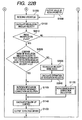
- FIGS. 22A and 22B By using FIGS. 22A and 22B , embodiment 3 will be described. The same flow as in FIGS. 7A and 7B according to embodiment 1 is included. Therefore, the same reference numerals and characters are used for the same flow, and the description will be omitted.
- the flow proceeds to S2610.
- S2610 it is determined whether the imaging magnification of shooting is 0.2 or more (predetermined value or more). In the case of 0.2 or more, the flow proceeds to S2620, and in the case of less than 0.2 (less than the predetermined value), the flow proceeds to S1130.
- S1130 rotation movement correction calculation is performed as in embodiment 1.
- the angular velocity ratio is fixed (stored) to the constant (specified constant) of 0.9, and in the next S2640, estimation of the present revolution angular velocity is calculated by multiplying the rotation angular velocity obtained in real time by the constant angular velocity ratio of 0.9, and the flow proceeds to the next S1120.
- the rotation revolution difference movement correction calculation is performed as in embodiment 1.
- the revolution angular velocity is sufficiently small with respect to the rotation angular velocity, and therefore, the image stabilization calculation is simplified by only performing rotation movement correction, which leads to enhancement in speed and reduction in power consumption. Further, the ratio of the revolution angular velocity to the rotation angular velocity rarely exceeds one, and when the ratio exceeds ⁇ 0.9, erroneous excessive correction is prevented by fixing the ratio to the constant 0.9.
Landscapes
- Physics & Mathematics (AREA)
- Engineering & Computer Science (AREA)
- Multimedia (AREA)
- Signal Processing (AREA)
- General Physics & Mathematics (AREA)
- Optics & Photonics (AREA)
- Adjustment Of Camera Lenses (AREA)
- Studio Devices (AREA)
Applications Claiming Priority (2)
| Application Number | Priority Date | Filing Date | Title |
|---|---|---|---|
| JP2009140255A JP4857363B2 (ja) | 2009-06-11 | 2009-06-11 | 像振れ補正装置および撮像装置 |
| PCT/JP2010/057729 WO2010143485A1 (en) | 2009-06-11 | 2010-04-23 | Image stabilization apparatus and image pickup apparatus |
Publications (3)
| Publication Number | Publication Date |
|---|---|
| EP2440970A1 EP2440970A1 (en) | 2012-04-18 |
| EP2440970A4 EP2440970A4 (en) | 2012-05-16 |
| EP2440970B1 true EP2440970B1 (en) | 2013-10-23 |
Family
ID=43308745
Family Applications (1)
| Application Number | Title | Priority Date | Filing Date |
|---|---|---|---|
| EP10786016.5A Not-in-force EP2440970B1 (en) | 2009-06-11 | 2010-04-23 | Image stabilization apparatus and image pickup apparatus |
Country Status (8)
| Country | Link |
|---|---|
| US (1) | US8711272B2 (zh) |
| EP (1) | EP2440970B1 (zh) |
| JP (1) | JP4857363B2 (zh) |
| KR (1) | KR101287931B1 (zh) |
| CN (1) | CN102804053B (zh) |
| BR (1) | BRPI1013048B1 (zh) |
| RU (1) | RU2498376C2 (zh) |
| WO (1) | WO2010143485A1 (zh) |
Families Citing this family (17)
| Publication number | Priority date | Publication date | Assignee | Title |
|---|---|---|---|---|
| JP2013017165A (ja) | 2011-06-10 | 2013-01-24 | Panasonic Corp | 撮像装置 |
| GB2508471B (en) * | 2012-11-29 | 2015-10-07 | Cooke Optics Ltd | Camera lens assembly |
| US9563105B1 (en) * | 2013-04-10 | 2017-02-07 | Ic Real Tech Inc. | Screw coupler enabling direct secure fastening between communicating electronic components |
| TW201442512A (zh) * | 2013-04-19 | 2014-11-01 | Hon Hai Prec Ind Co Ltd | 自動對焦設計系統、電子裝置及自動對焦設計方法 |
| JP6023999B2 (ja) * | 2013-04-25 | 2016-11-09 | 多摩川精機株式会社 | 空間安定装置 |
| JP2015034879A (ja) | 2013-08-08 | 2015-02-19 | キヤノン株式会社 | 像振れ補正装置およびその制御方法、レンズ鏡筒、光学機器、並びに撮像装置 |
| JP6410431B2 (ja) * | 2014-01-30 | 2018-10-24 | オリンパス株式会社 | カメラシステム |
| CN104792500B (zh) * | 2015-04-20 | 2017-07-14 | 中国科学院上海光学精密机械研究所 | 光学系统光束指向稳定性的诊断方法 |
| US11202011B2 (en) * | 2016-07-25 | 2021-12-14 | Canon Kabushiki Kaisha | Control apparatus, image capturing apparatus, lens apparatus, image capturing system, control method, and storage medium |
| WO2018070468A1 (ja) * | 2016-10-13 | 2018-04-19 | 富士フイルム株式会社 | ブレ補正装置、撮像装置、及びブレ補正方法 |
| JP7057628B2 (ja) | 2017-01-26 | 2022-04-20 | Omデジタルソリューションズ株式会社 | 撮像装置、及び、その像ぶれ量算出方法 |
| CN110419210B (zh) * | 2017-03-15 | 2021-01-12 | 富士胶片株式会社 | 摄像装置、摄像方法及记录介质 |
| WO2018230316A1 (ja) * | 2017-06-12 | 2018-12-20 | 富士フイルム株式会社 | ブレ検出装置、撮像装置、レンズ装置、撮像装置本体、ブレ検出方法及びブレ検出プログラム |
| JP7086571B2 (ja) * | 2017-11-16 | 2022-06-20 | キヤノン株式会社 | 撮像装置、レンズ装置およびこれらの制御方法 |
| JP6960324B2 (ja) * | 2017-12-19 | 2021-11-05 | 旭化成エレクトロニクス株式会社 | ブレ量算出装置、ブレ量補正装置、撮像装置、方法、およびプログラム |
| CN110731077B (zh) * | 2018-03-23 | 2021-10-01 | 华为技术有限公司 | 视频图像防抖方法和终端 |
| CH716570A2 (de) * | 2019-09-09 | 2021-03-15 | Andre Reber | Verfahren zur Verbesserung der Sehfähigkeit einer sehbehinderten Person mit einer portablen Sehhilfe. |
Family Cites Families (24)
| Publication number | Priority date | Publication date | Assignee | Title |
|---|---|---|---|---|
| DE3628480A1 (de) * | 1985-08-23 | 1987-03-05 | Canon Kk | Verfahren und vorrichtung zur kompensation einer bewegung eines bildes |
| JPH073514B2 (ja) * | 1985-12-26 | 1995-01-18 | キヤノン株式会社 | 像移動機構 |
| JP3103572B2 (ja) * | 1990-01-16 | 2000-10-30 | オリンパス光学工業株式会社 | カメラ装置 |
| DE69324530T2 (de) | 1992-07-15 | 1999-08-19 | Nikon Corp | Photographisches Gerät mit Bildzitterkorrektur |
| JP3513950B2 (ja) * | 1993-12-14 | 2004-03-31 | 株式会社ニコン | 像振れ補正カメラ |
| JPH07301839A (ja) * | 1994-05-10 | 1995-11-14 | Olympus Optical Co Ltd | カメラの手ブレ補正装置 |
| RU2095839C1 (ru) * | 1995-04-12 | 1997-11-10 | Акционерное общество закрытого типа "Наутэк-холдинг" | Устройство стабилизации оптического изображения |
| US5794078A (en) * | 1995-09-11 | 1998-08-11 | Nikon Corporation | Image movement correction of camera |
| US6429895B1 (en) * | 1996-12-27 | 2002-08-06 | Canon Kabushiki Kaisha | Image sensing apparatus and method capable of merging function for obtaining high-precision image by synthesizing images and image stabilization function |
| JPH11249185A (ja) * | 1998-03-04 | 1999-09-17 | Nikon Corp | カメラシステム及び交換レンズ |
| JP2004295027A (ja) | 2003-03-28 | 2004-10-21 | Nikon Corp | ブレ補正装置 |
| JP4717382B2 (ja) | 2004-06-15 | 2011-07-06 | キヤノン株式会社 | 光学機器 |
| JP2006091279A (ja) * | 2004-09-22 | 2006-04-06 | Canon Inc | 光学機器 |
| JP4667052B2 (ja) * | 2005-01-27 | 2011-04-06 | キヤノン株式会社 | 撮像装置並びにそのカメラ本体及び交換レンズ |
| JP2007034141A (ja) * | 2005-07-29 | 2007-02-08 | Olympus Imaging Corp | カメラシステム及びレンズユニット |
| JP4789614B2 (ja) * | 2005-12-26 | 2011-10-12 | キヤノン株式会社 | 防振制御装置およびその制御方法 |
| CN101454715B (zh) * | 2006-05-26 | 2011-03-30 | 日本胜利株式会社 | 图像模糊修正装置 |
| JP4827662B2 (ja) * | 2006-08-31 | 2011-11-30 | Hoya株式会社 | 焦点調節装置を備えたカメラ |
| JP4400611B2 (ja) * | 2006-10-26 | 2010-01-20 | カシオ計算機株式会社 | 撮像装置、ブレ補正方法、およびプログラム |
| JP2009105784A (ja) * | 2007-10-25 | 2009-05-14 | Sony Corp | 撮像装置 |
| JP4876066B2 (ja) * | 2007-12-19 | 2012-02-15 | キヤノン株式会社 | 映像処理装置及び映像処理システム及び映像処理方法及びプログラム |
| JP5430074B2 (ja) * | 2008-04-03 | 2014-02-26 | キヤノン株式会社 | 光学機器およびそれを備えた撮像装置 |
| US8199243B2 (en) * | 2008-04-28 | 2012-06-12 | Panasonic Corporation | Imaging device and camera body |
| KR20100085728A (ko) * | 2009-01-21 | 2010-07-29 | 삼성전자주식회사 | 촬영장치 및 이를 이용한 초점 검출 방법 |
-
2009
- 2009-06-11 JP JP2009140255A patent/JP4857363B2/ja not_active Expired - Fee Related
-
2010
- 2010-04-23 US US13/263,465 patent/US8711272B2/en not_active Expired - Fee Related
- 2010-04-23 RU RU2012100254/28A patent/RU2498376C2/ru not_active IP Right Cessation
- 2010-04-23 WO PCT/JP2010/057729 patent/WO2010143485A1/en active Application Filing
- 2010-04-23 EP EP10786016.5A patent/EP2440970B1/en not_active Not-in-force
- 2010-04-23 KR KR1020127000294A patent/KR101287931B1/ko active IP Right Grant
- 2010-04-23 CN CN201080026072.3A patent/CN102804053B/zh not_active Expired - Fee Related
- 2010-04-23 BR BRPI1013048-9A patent/BRPI1013048B1/pt not_active IP Right Cessation
Also Published As
| Publication number | Publication date |
|---|---|
| JP4857363B2 (ja) | 2012-01-18 |
| US20120038783A1 (en) | 2012-02-16 |
| BRPI1013048B1 (pt) | 2020-07-28 |
| CN102804053B (zh) | 2015-06-10 |
| EP2440970A4 (en) | 2012-05-16 |
| WO2010143485A1 (en) | 2010-12-16 |
| BRPI1013048A2 (pt) | 2016-04-05 |
| CN102804053A (zh) | 2012-11-28 |
| JP2010286651A (ja) | 2010-12-24 |
| EP2440970A1 (en) | 2012-04-18 |
| RU2012100254A (ru) | 2013-07-20 |
| US8711272B2 (en) | 2014-04-29 |
| KR20120025586A (ko) | 2012-03-15 |
| RU2498376C2 (ru) | 2013-11-10 |
| KR101287931B1 (ko) | 2013-07-19 |
Similar Documents
| Publication | Publication Date | Title |
|---|---|---|
| EP2440970B1 (en) | Image stabilization apparatus and image pickup apparatus | |
| US8339466B2 (en) | Image stabilization apparatus and image pickup apparatus | |
| JP5284169B2 (ja) | 像振れ補正装置およびそれを具備する光学機器、撮像装置 | |
| CN105814484B (zh) | 抖动校正装置及其调整方法、抖动校正电路、抖动校正方法、以及照相机模块及其光学元件的位置控制方法 | |
| JP3513950B2 (ja) | 像振れ補正カメラ | |
| JP6600232B2 (ja) | 像ブレ補正装置及び方法 | |
| EP2458426B1 (en) | Image pickup apparatus including image shake correction | |
| US5794078A (en) | Image movement correction of camera | |
| JP6105880B2 (ja) | 撮像装置およびその制御方法 | |
| JP2006300997A (ja) | 像振れ防止機能を有する撮像装置 | |
| US20140146191A1 (en) | Amount-of-shake sensing apparatus, imaging apparatus, and method for detecting the amount of shake | |
| JP2004295027A (ja) | ブレ補正装置 | |
| JP2007158853A (ja) | 振れ補正装置 | |
| CN109040573B (zh) | 抖动校正方法和抖动校正设备 | |
| JP5822548B2 (ja) | 像ブレ補正装置、像ブレ補正方法、撮像装置 | |
| JP3729214B2 (ja) | 像ブレ補正カメラ | |
| JP5854653B2 (ja) | 防振制御装置、撮像装置、及び防振制御方法 | |
| JPH1164914A (ja) | ブレ補正装置 | |
| JP3870501B2 (ja) | ブレ補正装置、及び、光学装置 | |
| JP4396117B2 (ja) | ブレ補正装置及び光学装置 | |
| JP2000081646A (ja) | 手振れ補正機能付きカメラ | |
| US10924672B2 (en) | Camera controller | |
| JP2000227613A (ja) | 手振れ補正装置 | |
| JP2007065117A (ja) | 像振れ補正装置 | |
| JP2013238647A (ja) | ブレ補正装置および光学機器 |
Legal Events
| Date | Code | Title | Description |
|---|---|---|---|
| PUAI | Public reference made under article 153(3) epc to a published international application that has entered the european phase |
Free format text: ORIGINAL CODE: 0009012 |
|
| 17P | Request for examination filed |
Effective date: 20120111 |
|
| AK | Designated contracting states |
Kind code of ref document: A1 Designated state(s): AT BE BG CH CY CZ DE DK EE ES FI FR GB GR HR HU IE IS IT LI LT LU LV MC MK MT NL NO PL PT RO SE SI SK SM TR |
|
| A4 | Supplementary search report drawn up and despatched |
Effective date: 20120417 |
|
| RIC1 | Information provided on ipc code assigned before grant |
Ipc: H04N 5/232 20060101ALI20120411BHEP Ipc: G03B 5/00 20060101AFI20120411BHEP Ipc: G02B 27/64 20060101ALI20120411BHEP |
|
| DAX | Request for extension of the european patent (deleted) | ||
| 17Q | First examination report despatched |
Effective date: 20120920 |
|
| GRAP | Despatch of communication of intention to grant a patent |
Free format text: ORIGINAL CODE: EPIDOSNIGR1 |
|
| INTG | Intention to grant announced |
Effective date: 20130508 |
|
| GRAS | Grant fee paid |
Free format text: ORIGINAL CODE: EPIDOSNIGR3 |
|
| GRAA | (expected) grant |
Free format text: ORIGINAL CODE: 0009210 |
|
| AK | Designated contracting states |
Kind code of ref document: B1 Designated state(s): AT BE BG CH CY CZ DE DK EE ES FI FR GB GR HR HU IE IS IT LI LT LU LV MC MK MT NL NO PL PT RO SE SI SK SM TR |
|
| REG | Reference to a national code |
Ref country code: GB Ref legal event code: FG4D |
|
| REG | Reference to a national code |
Ref country code: CH Ref legal event code: EP |
|
| REG | Reference to a national code |
Ref country code: AT Ref legal event code: REF Ref document number: 637901 Country of ref document: AT Kind code of ref document: T Effective date: 20131115 |
|
| REG | Reference to a national code |
Ref country code: IE Ref legal event code: FG4D |
|
| REG | Reference to a national code |
Ref country code: DE Ref legal event code: R096 Ref document number: 602010011237 Country of ref document: DE Effective date: 20131219 |
|
| REG | Reference to a national code |
Ref country code: NL Ref legal event code: VDEP Effective date: 20131023 |
|
| REG | Reference to a national code |
Ref country code: AT Ref legal event code: MK05 Ref document number: 637901 Country of ref document: AT Kind code of ref document: T Effective date: 20131023 |
|
| REG | Reference to a national code |
Ref country code: LT Ref legal event code: MG4D |
|
| PG25 | Lapsed in a contracting state [announced via postgrant information from national office to epo] |
Ref country code: NL Free format text: LAPSE BECAUSE OF FAILURE TO SUBMIT A TRANSLATION OF THE DESCRIPTION OR TO PAY THE FEE WITHIN THE PRESCRIBED TIME-LIMIT Effective date: 20131023 Ref country code: FI Free format text: LAPSE BECAUSE OF FAILURE TO SUBMIT A TRANSLATION OF THE DESCRIPTION OR TO PAY THE FEE WITHIN THE PRESCRIBED TIME-LIMIT Effective date: 20131023 Ref country code: NO Free format text: LAPSE BECAUSE OF FAILURE TO SUBMIT A TRANSLATION OF THE DESCRIPTION OR TO PAY THE FEE WITHIN THE PRESCRIBED TIME-LIMIT Effective date: 20140123 Ref country code: IS Free format text: LAPSE BECAUSE OF FAILURE TO SUBMIT A TRANSLATION OF THE DESCRIPTION OR TO PAY THE FEE WITHIN THE PRESCRIBED TIME-LIMIT Effective date: 20140223 Ref country code: BE Free format text: LAPSE BECAUSE OF FAILURE TO SUBMIT A TRANSLATION OF THE DESCRIPTION OR TO PAY THE FEE WITHIN THE PRESCRIBED TIME-LIMIT Effective date: 20131023 Ref country code: HR Free format text: LAPSE BECAUSE OF FAILURE TO SUBMIT A TRANSLATION OF THE DESCRIPTION OR TO PAY THE FEE WITHIN THE PRESCRIBED TIME-LIMIT Effective date: 20131023 Ref country code: LT Free format text: LAPSE BECAUSE OF FAILURE TO SUBMIT A TRANSLATION OF THE DESCRIPTION OR TO PAY THE FEE WITHIN THE PRESCRIBED TIME-LIMIT Effective date: 20131023 Ref country code: SE Free format text: LAPSE BECAUSE OF FAILURE TO SUBMIT A TRANSLATION OF THE DESCRIPTION OR TO PAY THE FEE WITHIN THE PRESCRIBED TIME-LIMIT Effective date: 20131023 |
|
| PG25 | Lapsed in a contracting state [announced via postgrant information from national office to epo] |
Ref country code: CY Free format text: LAPSE BECAUSE OF FAILURE TO SUBMIT A TRANSLATION OF THE DESCRIPTION OR TO PAY THE FEE WITHIN THE PRESCRIBED TIME-LIMIT Effective date: 20131023 Ref country code: LV Free format text: LAPSE BECAUSE OF FAILURE TO SUBMIT A TRANSLATION OF THE DESCRIPTION OR TO PAY THE FEE WITHIN THE PRESCRIBED TIME-LIMIT Effective date: 20131023 Ref country code: ES Free format text: LAPSE BECAUSE OF FAILURE TO SUBMIT A TRANSLATION OF THE DESCRIPTION OR TO PAY THE FEE WITHIN THE PRESCRIBED TIME-LIMIT Effective date: 20131023 Ref country code: AT Free format text: LAPSE BECAUSE OF FAILURE TO SUBMIT A TRANSLATION OF THE DESCRIPTION OR TO PAY THE FEE WITHIN THE PRESCRIBED TIME-LIMIT Effective date: 20131023 |
|
| PG25 | Lapsed in a contracting state [announced via postgrant information from national office to epo] |
Ref country code: PT Free format text: LAPSE BECAUSE OF FAILURE TO SUBMIT A TRANSLATION OF THE DESCRIPTION OR TO PAY THE FEE WITHIN THE PRESCRIBED TIME-LIMIT Effective date: 20140224 |
|
| REG | Reference to a national code |
Ref country code: DE Ref legal event code: R097 Ref document number: 602010011237 Country of ref document: DE |
|
| PG25 | Lapsed in a contracting state [announced via postgrant information from national office to epo] |
Ref country code: EE Free format text: LAPSE BECAUSE OF FAILURE TO SUBMIT A TRANSLATION OF THE DESCRIPTION OR TO PAY THE FEE WITHIN THE PRESCRIBED TIME-LIMIT Effective date: 20131023 |
|
| PG25 | Lapsed in a contracting state [announced via postgrant information from national office to epo] |
Ref country code: PL Free format text: LAPSE BECAUSE OF FAILURE TO SUBMIT A TRANSLATION OF THE DESCRIPTION OR TO PAY THE FEE WITHIN THE PRESCRIBED TIME-LIMIT Effective date: 20131023 Ref country code: SK Free format text: LAPSE BECAUSE OF FAILURE TO SUBMIT A TRANSLATION OF THE DESCRIPTION OR TO PAY THE FEE WITHIN THE PRESCRIBED TIME-LIMIT Effective date: 20131023 Ref country code: IT Free format text: LAPSE BECAUSE OF FAILURE TO SUBMIT A TRANSLATION OF THE DESCRIPTION OR TO PAY THE FEE WITHIN THE PRESCRIBED TIME-LIMIT Effective date: 20131023 Ref country code: CZ Free format text: LAPSE BECAUSE OF FAILURE TO SUBMIT A TRANSLATION OF THE DESCRIPTION OR TO PAY THE FEE WITHIN THE PRESCRIBED TIME-LIMIT Effective date: 20131023 Ref country code: RO Free format text: LAPSE BECAUSE OF FAILURE TO SUBMIT A TRANSLATION OF THE DESCRIPTION OR TO PAY THE FEE WITHIN THE PRESCRIBED TIME-LIMIT Effective date: 20131023 |
|
| PLBE | No opposition filed within time limit |
Free format text: ORIGINAL CODE: 0009261 |
|
| STAA | Information on the status of an ep patent application or granted ep patent |
Free format text: STATUS: NO OPPOSITION FILED WITHIN TIME LIMIT |
|
| PG25 | Lapsed in a contracting state [announced via postgrant information from national office to epo] |
Ref country code: DK Free format text: LAPSE BECAUSE OF FAILURE TO SUBMIT A TRANSLATION OF THE DESCRIPTION OR TO PAY THE FEE WITHIN THE PRESCRIBED TIME-LIMIT Effective date: 20131023 |
|
| 26N | No opposition filed |
Effective date: 20140724 |
|
| REG | Reference to a national code |
Ref country code: DE Ref legal event code: R097 Ref document number: 602010011237 Country of ref document: DE Effective date: 20140724 |
|
| PG25 | Lapsed in a contracting state [announced via postgrant information from national office to epo] |
Ref country code: MC Free format text: LAPSE BECAUSE OF FAILURE TO SUBMIT A TRANSLATION OF THE DESCRIPTION OR TO PAY THE FEE WITHIN THE PRESCRIBED TIME-LIMIT Effective date: 20131023 Ref country code: LU Free format text: LAPSE BECAUSE OF FAILURE TO SUBMIT A TRANSLATION OF THE DESCRIPTION OR TO PAY THE FEE WITHIN THE PRESCRIBED TIME-LIMIT Effective date: 20140423 |
|
| REG | Reference to a national code |
Ref country code: CH Ref legal event code: PL |
|
| REG | Reference to a national code |
Ref country code: FR Ref legal event code: ST Effective date: 20141231 |
|
| REG | Reference to a national code |
Ref country code: IE Ref legal event code: MM4A |
|
| PG25 | Lapsed in a contracting state [announced via postgrant information from national office to epo] |
Ref country code: LI Free format text: LAPSE BECAUSE OF NON-PAYMENT OF DUE FEES Effective date: 20140430 Ref country code: CH Free format text: LAPSE BECAUSE OF NON-PAYMENT OF DUE FEES Effective date: 20140430 |
|
| PG25 | Lapsed in a contracting state [announced via postgrant information from national office to epo] |
Ref country code: FR Free format text: LAPSE BECAUSE OF NON-PAYMENT OF DUE FEES Effective date: 20140430 Ref country code: SI Free format text: LAPSE BECAUSE OF FAILURE TO SUBMIT A TRANSLATION OF THE DESCRIPTION OR TO PAY THE FEE WITHIN THE PRESCRIBED TIME-LIMIT Effective date: 20131023 |
|
| PG25 | Lapsed in a contracting state [announced via postgrant information from national office to epo] |
Ref country code: IE Free format text: LAPSE BECAUSE OF NON-PAYMENT OF DUE FEES Effective date: 20140423 |
|
| PG25 | Lapsed in a contracting state [announced via postgrant information from national office to epo] |
Ref country code: MT Free format text: LAPSE BECAUSE OF FAILURE TO SUBMIT A TRANSLATION OF THE DESCRIPTION OR TO PAY THE FEE WITHIN THE PRESCRIBED TIME-LIMIT Effective date: 20131023 |
|
| PG25 | Lapsed in a contracting state [announced via postgrant information from national office to epo] |
Ref country code: SM Free format text: LAPSE BECAUSE OF FAILURE TO SUBMIT A TRANSLATION OF THE DESCRIPTION OR TO PAY THE FEE WITHIN THE PRESCRIBED TIME-LIMIT Effective date: 20131023 |
|
| PG25 | Lapsed in a contracting state [announced via postgrant information from national office to epo] |
Ref country code: BG Free format text: LAPSE BECAUSE OF FAILURE TO SUBMIT A TRANSLATION OF THE DESCRIPTION OR TO PAY THE FEE WITHIN THE PRESCRIBED TIME-LIMIT Effective date: 20131023 Ref country code: GR Free format text: LAPSE BECAUSE OF FAILURE TO SUBMIT A TRANSLATION OF THE DESCRIPTION OR TO PAY THE FEE WITHIN THE PRESCRIBED TIME-LIMIT Effective date: 20140124 |
|
| PG25 | Lapsed in a contracting state [announced via postgrant information from national office to epo] |
Ref country code: HU Free format text: LAPSE BECAUSE OF FAILURE TO SUBMIT A TRANSLATION OF THE DESCRIPTION OR TO PAY THE FEE WITHIN THE PRESCRIBED TIME-LIMIT; INVALID AB INITIO Effective date: 20100423 Ref country code: TR Free format text: LAPSE BECAUSE OF FAILURE TO SUBMIT A TRANSLATION OF THE DESCRIPTION OR TO PAY THE FEE WITHIN THE PRESCRIBED TIME-LIMIT Effective date: 20131023 |
|
| PG25 | Lapsed in a contracting state [announced via postgrant information from national office to epo] |
Ref country code: MK Free format text: LAPSE BECAUSE OF FAILURE TO SUBMIT A TRANSLATION OF THE DESCRIPTION OR TO PAY THE FEE WITHIN THE PRESCRIBED TIME-LIMIT Effective date: 20131023 |
|
| PGFP | Annual fee paid to national office [announced via postgrant information from national office to epo] |
Ref country code: GB Payment date: 20180427 Year of fee payment: 9 |
|
| GBPC | Gb: european patent ceased through non-payment of renewal fee |
Effective date: 20190423 |
|
| PG25 | Lapsed in a contracting state [announced via postgrant information from national office to epo] |
Ref country code: GB Free format text: LAPSE BECAUSE OF NON-PAYMENT OF DUE FEES Effective date: 20190423 |
|
| PGFP | Annual fee paid to national office [announced via postgrant information from national office to epo] |
Ref country code: DE Payment date: 20210323 Year of fee payment: 12 |
|
| REG | Reference to a national code |
Ref country code: DE Ref legal event code: R119 Ref document number: 602010011237 Country of ref document: DE |
|
| PG25 | Lapsed in a contracting state [announced via postgrant information from national office to epo] |
Ref country code: DE Free format text: LAPSE BECAUSE OF NON-PAYMENT OF DUE FEES Effective date: 20221103 |