WO2010143485A1 - Image stabilization apparatus and image pickup apparatus - Google Patents
Image stabilization apparatus and image pickup apparatus Download PDFInfo
- Publication number
- WO2010143485A1 WO2010143485A1 PCT/JP2010/057729 JP2010057729W WO2010143485A1 WO 2010143485 A1 WO2010143485 A1 WO 2010143485A1 JP 2010057729 W JP2010057729 W JP 2010057729W WO 2010143485 A1 WO2010143485 A1 WO 2010143485A1
- Authority
- WO
- WIPO (PCT)
- Prior art keywords
- angular velocity
- shooting
- image stabilization
- rotation
- principal point
- Prior art date
Links
Classifications
-
- G—PHYSICS
- G03—PHOTOGRAPHY; CINEMATOGRAPHY; ANALOGOUS TECHNIQUES USING WAVES OTHER THAN OPTICAL WAVES; ELECTROGRAPHY; HOLOGRAPHY
- G03B—APPARATUS OR ARRANGEMENTS FOR TAKING PHOTOGRAPHS OR FOR PROJECTING OR VIEWING THEM; APPARATUS OR ARRANGEMENTS EMPLOYING ANALOGOUS TECHNIQUES USING WAVES OTHER THAN OPTICAL WAVES; ACCESSORIES THEREFOR
- G03B5/00—Adjustment of optical system relative to image or object surface other than for focusing
-
- G—PHYSICS
- G02—OPTICS
- G02B—OPTICAL ELEMENTS, SYSTEMS OR APPARATUS
- G02B27/00—Optical systems or apparatus not provided for by any of the groups G02B1/00 - G02B26/00, G02B30/00
- G02B27/64—Imaging systems using optical elements for stabilisation of the lateral and angular position of the image
- G02B27/646—Imaging systems using optical elements for stabilisation of the lateral and angular position of the image compensating for small deviations, e.g. due to vibration or shake
-
- H—ELECTRICITY
- H04—ELECTRIC COMMUNICATION TECHNIQUE
- H04N—PICTORIAL COMMUNICATION, e.g. TELEVISION
- H04N23/00—Cameras or camera modules comprising electronic image sensors; Control thereof
- H04N23/60—Control of cameras or camera modules
- H04N23/68—Control of cameras or camera modules for stable pick-up of the scene, e.g. compensating for camera body vibrations
- H04N23/681—Motion detection
- H04N23/6812—Motion detection based on additional sensors, e.g. acceleration sensors
-
- H—ELECTRICITY
- H04—ELECTRIC COMMUNICATION TECHNIQUE
- H04N—PICTORIAL COMMUNICATION, e.g. TELEVISION
- H04N23/00—Cameras or camera modules comprising electronic image sensors; Control thereof
- H04N23/60—Control of cameras or camera modules
- H04N23/68—Control of cameras or camera modules for stable pick-up of the scene, e.g. compensating for camera body vibrations
- H04N23/682—Vibration or motion blur correction
- H04N23/685—Vibration or motion blur correction performed by mechanical compensation
- H04N23/687—Vibration or motion blur correction performed by mechanical compensation by shifting the lens or sensor position
-
- G—PHYSICS
- G03—PHOTOGRAPHY; CINEMATOGRAPHY; ANALOGOUS TECHNIQUES USING WAVES OTHER THAN OPTICAL WAVES; ELECTROGRAPHY; HOLOGRAPHY
- G03B—APPARATUS OR ARRANGEMENTS FOR TAKING PHOTOGRAPHS OR FOR PROJECTING OR VIEWING THEM; APPARATUS OR ARRANGEMENTS EMPLOYING ANALOGOUS TECHNIQUES USING WAVES OTHER THAN OPTICAL WAVES; ACCESSORIES THEREFOR
- G03B2217/00—Details of cameras or camera bodies; Accessories therefor
- G03B2217/005—Blur detection
Definitions
- the present invention relates to an image stabilization apparatus which prevents deterioration of a shot image by correcting an image blur due to shake, and an image pickup apparatus including the image stabilization apparatus.
- FIG. 23 is a view showing an outline of an image stabilization apparatus included in the conventional camera.
- a shake which occurs to the camera has six degrees of freedom in total, which are rotational movements of three degrees of freedom constituted of pitching, yawing and rolling movement, and translation movements of three degrees of freedom constituted of movements in an X-axis, a Y-axis and a Z-axis directions.
- the image stabilization apparatuses which are commercialized at present usually corrects the image blur due to the rotational movements of two degrees of freedom constituted of pitching and yawing movements .
- Movement of camera is monitored by an angular velocity sensor 130.
- As the angular velocity sensor a piezoelectric vibration angular velocity sensor that detects a Coriolis force which is caused by rotation is generally used.
- the angular velocity sensor 130 contains three detectors which perform detection of pitching movement that is the rotation around the Z-axis in FIG. 23, detection of yawing movement that is the rotation around the Y-axis in FIG. 23, and detection of rolling movement that is the rotation around the X-axis (optical axis) in FIG. 23.
- output of the angular velocity sensor 130 is sent to a lens CPU 106, and a target drive position of a correcting lens 101 for image stabilization is calculated.
- instruction signals are sent to voltage drivers 161x and 161y, and the voltage drivers 161x and l ⁇ ly follow the instruction signals, and drive lens drivers 12Ox and 12Oy.
- the position of the correcting lens 101 is monitored by lens position detectors 11Ox and 11Oy, and is fed back to the lens CPU 106.
- the lens CPU 106 performs positional control of the correcting lens 101 based on the target drive position and the position of the correcting lens 101. By driving the correcting lens according to the shake like this, image blur caused by shake can be corrected.
- image stabilization apparatus detection of movement of camera due to shake is performed by only the angular velocity sensor 130, and therefore, the angular movement (rotational movement) can be monitored, but movement which causes the optical axis to move parallel vertically or laterally (hereinafter, referred to as parallel movement) cannot be monitored. Accordingly, image stabilization can be performed only for the movements of the two degrees of freedom constituted of pitching and yawing movements.
- the case of performing shooting by using a micro lens with a focal length of 100 mm will be described as an example.
- the angular velocity sensor output substantially 0.8 deg/s
- the shooting magnification ⁇ is substantially zero.
- the shooting magnification is very large, and the influence of parallel movement cannot be ignored.
- the moving velocity in the vertical direction is 1 mm/s
- the image on the image plane moves also in velocity of 1 mm/s.
- the movement width in the image plane at the time of performing shooting with an exposure time of 1/15 second becomes 67 ⁇ m, and the image blur due to parallel movement cannot be ignored.
- model and mathematical expression which expresses the movement of an object in a space in a field of physics and engineering will be described.
- model expressing movement of the object on a plane an ordinary object will be described for facilitating description.
- the movement and the position of the object can be uniquely defined.
- the first one is the model expressing a parallel movement and a rotational movement (see FIGS. 24A and 24B) .
- the position of the object can be determined if defining the three degrees of freedom: a position X(t) in the X-axis direction; a position Y(t) in the Y-axis direction; and the rotational angle ⁇ (t) of the object itself are specified as shown in FIG. 24A.
- the movement of the object can be expressed by three components of an X-axis direction translation velocity
- This model is the commonest.
- the second one is the model expressing an instantaneous center of rotation and a rotation radius (see FIG. 25) .
- the movement within the plane can be expressed by a locus f (t) of the instantaneous center of rotation and the rotation velocity at the instant.
- This model is often used in the analysis of a link mechanism in mechanics.
- cameras equipped with a function of correcting a parallel movement are proposed in Japanese Patent Application Laid-Open No.
- 2004-295027 uses the concept of an instantaneous center which is frequently used in the mechanics, as the model expressing the movement in the space. This is the idea that the movement in the space can be expressed by a succession of the rotational movement, that is, the movement in the space is a rotational movement with a certain radius with a certain point as the center at the instant, and is the rotational movement of the radius with the next certain point as the center at the next instant. Therefore, it can be said that in Japanese Patent Application Laid-Open No. 2004-295027, the movement of camera due to shake is modeled as a succession of the rotational movement having the instantaous center.
- the correction error component which will be described later is output from the acceleration sensor (accelerometer) , but Japanese Patent Application Laid-Open No. H07-225405 and Japanese Patent Application Laid-Open No. 2004-295027 do not have any corresponding technical disclosure.
- the present invention is made in view of the aforementioned problems, and has an object to provide an image stabilization apparatus and an image pickup apparatus which enable accurate image stabilization without a control failure, reduces a calculation amount, and can minimize an error amount accompanying a change in principal point position of a shooting optical system, in whatever state an angular movement and a parallel movement coexist.
- an image stabilization apparatus adopts a constitution characterized by having a shooting optical system that shoots an object, in which a principal point of the shooting optical system moves to a second principal point position from a first principle position in an optical axis direction of the shooting optical system, and an acceleration detector that detects an acceleration which is applied to the image stabilization apparatus and outputs the acceleration and is disposed between the first principal point position and the second principal point position in the optical axis direction of the shooting optical system.
- FIG. 1 is a block diagram illustrating a main part of an image pickup apparatus that is embodiment 1 according to the present invention.
- FIG. 2 is a simplified diagram of a camera state projected to an XY plane of embodiment 1.
- FIG. 3 is a diagram illustrating a principal point position and a position of an accelerometer in embodiment 1.
- FIGS. 4A and 4B are diagrams illustrating error ratio functions of accelerometer outputs in the state of FIG. 3.
- FIG. 5 is a diagram illustrating an error ratio function of an accelerometer output at an infinite position.
- FIG. 6 is a diagram illustrating a position in which an error ratio of the accelerometer output in the state of FIG. 3 becomes the minimum.
- FIG. 7 which is composed of FIGS. 7A and 7B are flowcharts illustrating an operation of embodiment 1.
- FIG. 8A is a diagram illustrating a coordinate system fixed onto a camera.
- FIG. 8B is a diagram illustrating a top view of the camera.
- FIG. 8C is a diagram illustrating a front view of the camera.
- FIG. 8D is a diagram illustrating a side view of the camera.
- FIG. 9 is a view expressing only an optical system of the camera in a three-dimensional space.
- FIGS. 1OA and 1OB are views illustrating a polar coordinate system and an orthogonal coordinate system of a principal point A.
- FIG. 11 is a coordinate map at the time of being projected to an X 9 Y 9 plane and a Z 9 X 9 plane.
- FIG. 12 is a diagram illustrating a camera state projected to the X9Y 9 plane.
- FIG. 13 is a diagram illustrating a camera state projected to the ZgX 9 plane.
- FIG. 15 is a view of a camera initial state in an 0- XYZ coordinate system.
- FIG. 16 is a basic explanatory diagram of a polar coordinate system.
- FIG. 17 is a diagram illustrating a camera state which is projected to a two-dimensional XY coordinate system.
- FIG. 18 is a diagram illustrating a camera state projected to a two-dimensional ZX coordinate system.
- FIGS. 19A and 19B are diagrams illustrating error ratio functions and the like of accelerometer outputs according to embodiment 2.
- FIG. 20 is a diagram illustrating a position where the error ratio according to embodiment 2 becomes the minimum.
- FIG. 21 is a diagram illustrating a position where an error ratio according to a modified example of embodiment 2 becomes the minimum.
- FIG. 22 is composed of FIGS. 22A and 22B are flowcharts illustrating an operation of embodiment 3.
- FIG. 23 is a view illustrating an image stabilization apparatus of a camera of a conventional example.
- FIGS. 24A and 24B are diagrams illustrating definitions of an object position and an object velocity in an ordinary two-dimensional coordinate system.
- FIG. 25 is a diagram illustrating a definition of an ordinary locus of instantaneous center of rotation.
- the shake movement of the camera held by human hands, and an image movement which occurs on an image plane as a result of the shake movement of the camera will be expressed by "rotation revolution movement expression" with the movement model expressed by a rotation movement and a revolution movement and a geometrical-optical expression being combined.
- the present embodiment is an image stabilization apparatus which calculates a camera movement from the measured values of an accelerometer and an angular velocity sensor, and the rotation revolution movement expression, and further calculates an image movement. By performing drive control of a part or whole of the shooting lens or a part or whole of the image pickup device based on a calculated value of the image movement, the image blur is corrected.
- the present invention provides an image stabilization apparatus which corrects an image blur by performing image processing of a shot image based on the calculated value of the image movement obtained from the rotation revolution movement expression.
- FIG. 1 is a block diagram illustrating a main part of an image pickup apparatus (camera system) including an image stabilization apparatus according to embodiment 1 of the present invention.
- the parts which performs the same functions as in the prior art are assigned with the same reference numerals and characters, and the redundant descriptions will be properly omitted.
- An image stabilization apparatus is provided in a lens-barrel 102 attachable to and detachable from a camera body 201, and performs blur correction with respect to the directions of five degrees of freedom of pitching (rotation around an Z2 ⁇ axis) , yawing (rotation around Y2 ⁇ axis) , an Y 2 ⁇ axis direction, a Z 2 ⁇ axis direction and an X2-axis (optical axis) direction.
- pitching rotation around an Z2 ⁇ axis
- yawing rotation around Y2 ⁇ axis
- Y 2 ⁇ axis direction a Z 2 ⁇ axis direction
- X2-axis optical axis
- an image stabilization system in the pitching rotation and the Y 2 - axis direction, and an optical axis direction image stabilization system in the X 2 -axis (optical axis) direction are shown, and an image stabilization system in the yawing rotation and the ⁇ 2 -axis direction is the same as the image stabilization system of the pitching rotation and the Y 2 ⁇ axis direction.
- An angular velocity sensor 130 is an angular velocity detector which is floatingly supported with respect to the lens barrel 102, and detects the angular velocity of the movement which occurs to the camera body 201 (lens barrel 102).
- the angular velocity sensor 130 according to the embodiment 1 is a piezoelectric vibration angular velocity sensor that detects Coriolis force which is generated by rotation.
- the angular velocity sensor 130 is an angular velocity sensor internally having sensitivity axes for three axis rotation of pitching, yawing and rolling. The reason why the angular velocity sensor 130 is floatingly supported is to eliminate the influence of mechanical vibration accompanying the mechanism operation of the camera as much as possible.
- the angular velocity sensor 130 outputs an angular velocity signal corresponding to a detected angular velocity to a filter 160c.
- An accelerometer 121 is an acceleration detector that detects the acceleration of the movement which occurs to the camera body 201 (lens barrel 102).
- the accelerometer 121 according to the embodiment 1 is a triaxial accelerometer having three sensitivity axes with respect to the three directions of the X-axis, Y-axis and Z-axis, and is floatingly supported by the lens barrel 102.
- the accelerometer 121 is floatingly supported for the same reason as the case of the angular velocity sensor 130.
- the accelerometer 121 is a triaxial acceleration sensor (acceleration sensor using a weight) in the present embodiment, and the frequency characteristics of two axes are equally high, but the characteristic of the remaining one axis is low. Therefore, in order to detect the accelerations in the Y 2 -axis direction and the Z 2 ⁇ axis direction orthogonal to the optical axis, the two axes with high sensitivity are used, and the one axis low in characteristic is aligned with the X2 ⁇ axis (optical axis direction) . This is for precisely detecting the accelerations in the Y 2 -axis direction and the Z 2 ⁇ axis direction which have a large influence on image blur correction.
- the output of the accelerometer 121 is A/D-converted after passing through a low pass filter (LPF) such as a filter 160a or the like, and is input to an IS (image stabilizing) lens correction calculator 107 in a lens CPU 106.
- the accelerometer 121 may be mounted to a movable mirror frame which moves in the optical axis direction during zooming or the like, a frame that holds the other optical system, or a unit in an optical system such as a stop, but in such a case, it is necessary to enable the position of the accelerometer 121 with respect to the principal point position after zooming to be detected.
- the angular velocity sensor 130 is of a vibratory gyro type as described above, and vibrates at 26 KHz. Accordingly, if these sensors are mounted on the same substrate, the accelerometer 121 is likely to pick up the vibration noise, and therefore, the accelerometer 121 and angular velocity sensor 130 are mounted on separate substrates.
- An image stabilizing lens driver 120 is a driver (actuator) which generates a drive force for driving a correcting lens 101 for correction of the image blur within the plane (within the Y 2 Z 2 plane) perpendicular to an optical axis I.
- the image stabilizing lens driver 120 generates a drive force in the Y 2 -axis direction, and drives the correcting lens 101 when a coil not illustrated is brought into an energized state by the drive current output by a voltage driver 161.
- a lens position detector 110 is an optical position detector which detects the position of the correcting lens 101 in the plane orthogonal to the optical axis I.
- the lens position detector 110 monitors the present position of the correcting lens 101, and feeds back the information concerning the present position of the correcting lens 101 to an image stabilizing controller 108 via an A/D converter.
- the lens CPU 106 is a central processor that performs various controls of the lens barrel 102 side.
- the lens CPU 106 calculates the focal length based on the pulse signal output by a focal length detector 163, and calculates an object distance based on the pulse signal output by an object distance detector 164.
- the image stabilizing lens correction calculator 107, the image stabilizing controller 108 and an autofocus lens controller 401 are provided.
- the lens CPU 106 can perform communication with a body CPU 109 via a lens junction 190 provided between the lens barrel 102 and the camera body 201.
- An image blur correction start command is sent from the body CPU 109 synchronously with half depression ON of a release switch 191 and an image blur correction stop command is sent to the CPU 106 synchronously with half depression OFF.
- the lens CPU 106 monitors the state of a blur correction switch (SW) 103 provided in the lens barrel 102. If the blur correction switch 103 is ON, the lens CPU 106 performs image blur correction control, and if the blur correction switch 103 is OFF, the lens CPU 106 ignores the image blur correction start command from the body CPU 109 and does not perform blur correction.
- SW blur correction switch
- the image stabilizing lens correction calculator 107 is a part which converts the output signals of the filters 160a and 160c into the target velocity information for driving the lens barrel 102 to the target position.
- the image stabilizing controller 108, the filters 160a and 160c, an EEPROM 162, the focal length detector 163, and the object distance detector 164 are connected to the image stabilizing lens correction calculator 107.
- the autofocus lens controller 401 has an optical axis direction movement velocity calculator 402 which performs calculation for performing optical axis direction movement correction by using the accelerometer output value from the image stabilizing lens correction calculator 107, and outputs the calculation result to an autofocus lens voltage driver 172.
- An autofocus lens 140 can be driven in the optical axis direction by an autofocus lens driver 141 using an ultrasonic motor or a stepping motor as a drive source.
- the autofocus lens voltage driver 172 generates a voltage for performing drive control of the autofocus lens driver 141.
- the image stabilizing lens correction calculator 107 captures the output signals (analog signals) output from the angular velocity sensor 130 and the accelerometer 121 through the filters 160a and 160c by quantizing the signals by A/D conversion. Based on the focal length information obtained from the focal length detector 163, the object distance information obtained from the object distance detector 164 and the information peculiar to the lens which is written in the EEPROM 162, the image stabilizing lens correction calculator 107 converts the signals into the target drive velocity of the correcting lens 101. The conversion method (calculating method) to the target drive position performed by the image stabilizing lens correction calculator 107 will be described in detail later.
- the target velocity signal which is the information of the target drive velocity calculated by the image stabilizing lens correction calculator 107 is output to the image stabilizing controller 108.
- the image stabilizing controller 108 is the part which controls the image stabilizing lens driver 120 via the voltage driver 161, and performs follow-up control so that the correcting lens 101 is driven as the information of the target drive velocity.
- the image stabilizing controller 108 converts the position detection signal (analog signal) output by the lens position detector 110 into a digital signal and captures the digital signal.
- the input part to the image stabilizing controller 108 is for the target velocity signal converted into the target drive velocity of the correcting lens 101 which is the output of the image stabilizing lens correction calculator 107, and another input part is for the positional information of the correcting lens 101 which is obtained by the lens position detector 110.
- velocity control is performed by using the deviation between the target drive velocity of the correcting lens 101 and the actual velocity information.
- the image stabilizing controller 108 calculates a drive signal based on the target drive velocity, velocity information of the correcting lens 101 and the like, and outputs the digital drive signal to the voltage driver 161.
- PID control is performed by using the deviation of the target positional information and the lens positional information of the correcting lens 101.
- the image stabilizing controller 108 calculates the drive signal based on the target positional information, the positional information of the correcting lens 101 and the like, and outputs the digital drive signal to the voltage driver 161.
- the filters 160a and 160c are filters which remove predetermined frequency components from the output signals of the angular velocity sensor 130 and the accelerometer 121, and cut the noise component and the DC component included in the high-frequency band.
- the filters 160a and 160c perform A/D conversion of the angular velocity signals after the predetermined frequency components are removed, and thereafter, output the angular velocity signals to the image stabilizing lens correction calculator 107.
- the voltage driver 161 is a driver which supplies power to the image stabilizing driver 120 according to the input drive signal (drive voltage) .
- the voltage driver 161 performs switching for the drive signal, applies a voltage to the image stabilizing lens driver 120 to drive the image stabilizing lens driver 120.
- the EEPROM 162 is a nonvolatile memory which stores lens data that is various kinds of unique information concerning the lens barrel 102, the coefficients for converting the pulse signals output by the object distance detector 164 into physical quantities.
- the focal length detector 163 is a zoom encoder which detects a focal length. The focal length detector 163 outputs the pulse signal corresponding to a focal length value to the image stabilizing lens correction calculator 107.
- the object distance detector 164 is a focusing encoder for detecting the distance to an object. The object distance detector 164 detects the position of a shooting optical system 105 (autofocus lens 140) , and outputs the pulse signal corresponding to the position to the image stabilizing lens correction calculator 107.
- the position of the principal point A of the shooting optical system 105 is calculated as will be described later.
- the positional information of the principal point A of the shooting optical system 105 stored in the EEPROM 162 is read, and control which will be described later is performed.
- the body CPU 109 is a central processor which performs various controls of the entire camera system.
- the body CPU 109 transmits a blur correction start command to the lens CPU 106 based on the ON operation of the release switch 191.
- the body CPU 109 transmits a blur correction stop command to the lens CPU 106 based on the OFF operation of the release switch 191.
- various kinds of processing are performed other than them.
- Information on the release switch 191 is input to the body CPU 109, and the release switch 191 can detect half depressing or fully depressing operation of the release button not illustrated.
- the release switch 191 is a switch which detects the half depressing operation of the release button not illustrated, starts a series of shooting preparing operations, detects a fully depressing operation of the release button and starts a shooting operation.
- a rotation angular velocity calculator 301 calculates a rotation angular velocity based on the angular velocity sensor output value.
- the angular velocity sensor output value and the rotation angular velocity are generally in the linear relation, and therefore, the rotation angular velocity can be obtained by multiplying the angular velocity sensor output value by a coefficient.
- a high-pass filter 303 is a filter which transmits a frequency component necessary for blur correction.
- a revolution angular velocity calculator 304 can obtain a revolution angular acceleration by dividing a
- a rotation revolution difference image stabilization amount calculator 305 calculates the image movement velocity in the Y 2 direction of the image pickup surface of the image pickup device 203 by substituting a read imaging magnification: ⁇ , an actual focal length value: f, and the rotation angular velocity and the revolution angular
- the obtained image movement velocity becomes a target drive velocity.
- the image movement velocity in the Z 2 direction of the image pickup surface can be similarly obtained from expression (16) which will be described later, but the description will be omitted here.
- a theoretical formula selector 306 selects whether the formula of rotation revolution difference movement correction using a difference between the rotation angular velocity and the revolution angular velocity, or the formula of rotation movement correction using only a rotation angular velocity as the formula used for correction calculation according to the ratio of the revolution angular velocity to the rotation angular velocity.
- ⁇ represents an imaging magnification [ (without unit) ] at the time of image blur correction of the shooting lens of this camera
- f represents an actual focal length [mm] at the time of image blur correction of the shooting lens of this camera
- (l+ ⁇ )f represents an image side focal length [mm]
- rotation angular velocity [rad/sec] represents time derivative value of revolution angle ⁇ axy with an origin 0 as the center
- the revolution angular velocity [rad/sec] represents that the image movement velocity vector indicates the direction rotated by 90 degrees from the X 2 ⁇ axis (optical axis) in the polar coordinate system because of power.
- VdCXy(O 1 -X 1 Y 1 ) in the moving coordinate system O2-X2Y2 in the XY plane which is expression (15) will be described later, and here, the meaning of this formula will be described with reference to FIG. 2.
- FIG. 2 shows a schematic diagram of a state of a camera which is projected on an XY plane. Here, the outer shape and the lens of the camera are illustrated.
- a principal point A xy of the optical system, an accelerometer B xy , a center C xy of the image pickup device In the camera, a principal point A xy of the optical system, an accelerometer B xy , a center C xy of the image pickup device
- An origin O 4 of the coordinate system O 4 -X 4 Y 4 is fixed to a principal point A xy of the optical system.
- an X 4 -axis keeps a parallel state with respect to the X-axis
- a Y 4 ⁇ axis keeps the parallel state with respect to a Y-axis.
- An origin O2 of a coordinate system O2-X2Y2 is fixed to the principal point A xy , and moves integrally with the camera. In this case, the X 2 -axis is always matched with the optical axis of this camera.
- the angle around the origin O2 from the X 4 -axis to the X 2 -axis is set as the rotation angle ⁇ caxy .
- the angle around the origin 0 from the X-axis to a scalar r axy is set as a revolution angle ⁇ axy .
- Scalar represents an object side focal length, ⁇ is an imaging magnification.
- a gravity acceleration vector at the principal point A xy has an angle ⁇ gxy around the principal point A xy from the X 4 - axis to the vector by normal rotation
- the approximate expression means that the image movement velocity in the Y 2 direction in the image pickup surface can be expressed by -(image side focal length) x (value obtained by subtracting the revolution angular velocity from the rotation angular velocity) .
- the exact formula without approximation is expression (12).
- the exact formula expression (12) may be used.
- the components of the yawing angle movement of the camera shake on the ZX plane and the parallel movement in the Z 2 -direction are expressed by the rotation revolution movement formula, and the ⁇ 2 direction image movement (image movement in the lateral direction of the image pickup surface) velocity in the image pickup device surface is obtained by the approximate expression expression (16) .
- the fourth term, the fifth term, the sixth term and the seventh term are unrequired terms for calculation, and unless they are erased, they become the error components at the time of obtaining the revolution angular velocity .
- the fourth term represents Coriolis force, and if the movement in the camera optical axis direction is small, the velocity in the optical axis direction , the fourth term is the term which can be ignored. Expression (27) will be also described later.
- the fifth term and the sixth term are error components which are included in the accelerometer output A C cy2(o-x2y2) since the accelerometer 121 cannot be disposed in the ideal principal point position A, and is disposed in
- centripetal force which is generated due to the rotation of the accelerometer 121 around the principal point A.
- rbaxy and ⁇ baxy represent the coordinates of the position B where the accelerometer 121 is mounted, and are known.
- the sixth term is the acceleration component when the accelerometer 121 rotates around the principal point A, and r ba ⁇ y and represent the coordinates of the position B where the accelerometer 121 is mounted, and are known. can be calculated by differentiating the value of the angular velocity sensor 130 mounted to the camera. Therefore, the value of the sixth term can be calculated.
- the seventh term is the influence of the
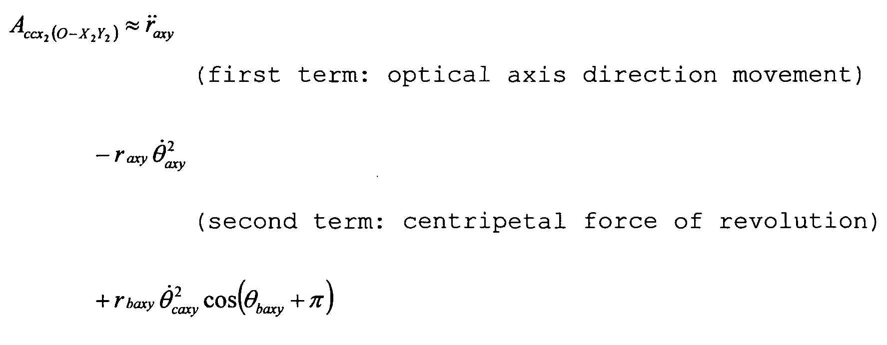
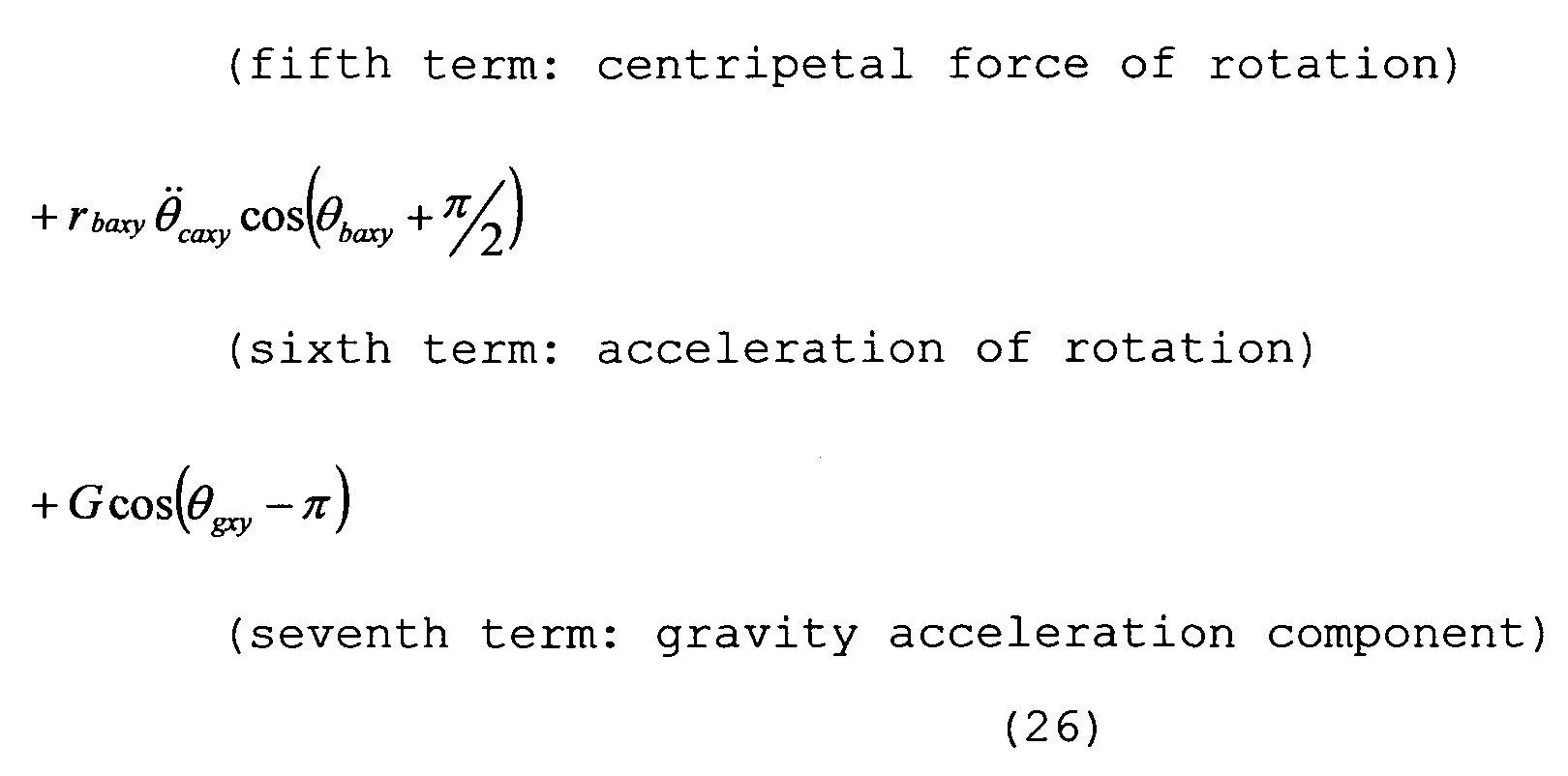
- the accelerometer output A CCX 2(o-x2Y2) in the X 2 -axis direction that is an optical axis for use in optical axis direction movement correction is represented by expression (26) .
- optical axis direction movement correction is only the first term (acceleration in the optical axis direction) .
- the second term, the fifth term, the sixth term and the seventh term are the components unrequired for the optical axis direction movement correction, and unless they are erased, they become error components at the time of obtaining the acceleration in the X 2 -axis direction which is the optical axis.
- the second term, the fifth term, the sixth term and the seventh term can be deleted by the similar method to the case of expression (27). Expression (26) will also be described later.
- the error components included in the output of the accelerometer 121 can be erased, but if the correction calculation is performed, blur correction operation start is delayed by the calculation time, and accurate blur correction cannot be made.
- FIG. 3 is a sectional view of the lens barrel 102, and is for describing the arrangement of the shooting optical system 105, the accelerometer 121 and the angular velocity sensor 131.
- FIG. 3 is a sectional view of the lens barrel 102, and is for describing the arrangement of the shooting optical system 105, the accelerometer 121 and the angular velocity sensor 131.
- the angular velocity sensor 131 is placed at an arbitrary position of the lens barrel 102, but the accelerometer 121 is placed at the position in the optical axis I direction between the principal point position Al (first point) at the time of equal-magnification shooting and the principal point position A2 (second point) at the time of infinity shooting.
- the accelerometer 121 is placed at the position in the optical axis direction, where the shooting magnification ⁇ becomes 0.5.
- the position in the optical axis I direction of the accelerometer 121 is set as a principal point position A3, the distance in the optical axis I direction from the principal point position Al at the time of equal- magnification shooting is set as ⁇ X, and the distance in the direction perpendicular to the optical axis I is set as ⁇ Y.
- r baxy ⁇ Y/sin ⁇ baxy is satisfied.
- tan ⁇ baxy ⁇ Y/ ⁇ X is satisfied.
- the fourth term in expression (27) can be ignored, and the seventh term also can be eliminated by filtering processing of a circuit. Therefore, the outputs of the accelerometer 121 after the filtering processing are the third term, the fifth term and the sixth term, and therefore, when the ratio of the accelerometer position error function g( ⁇ ba ) included in the output of the accelerometer 121 and represented by expression (30) is set as an error ratio function f( ⁇ ba ), the error ratio function f ( ⁇ ba) can be expressed as follows.
- FIG. 4A illustrates the error ratio in each imaging magnification which is obtained by obtaining the focal length f of the shooting optical system 105 and the imaging magnification at the time, in Expression (33) .
- FIG. 4B and FIG. 5 illustrate the error ratios at the time of disposing the accelerometer 121 at the equal-magnification position and the infinity position, for example.
- FIG. 6 illustrates how the result of sum of products of the values at the respective imaging magnifications of the error ratios obtained as illustrated in FIGS. 4A, 4B and 5 changes when the accelerometer 121 is disposed at the respective shooting magnifications. As illustrated in FIG.
- FIGS. 7A and 7B are flowcharts illustrating the flow of the operation relating to the image stabilizing lens correction of the image stabilization apparatus in embodiment 1.
- the operation relating to the correction amount calculation of the correcting lens 101 will be described according to FIGS. 7A and 7B.
- step (hereinafter, described as S) 1010 when the blur correction SW 103 is in an ON state, a correction start command is output from the camera body 201 by half depression ON of the release switch 191. By receiving the correction start command, the blur correction operation is started.
- S1020 it is determined whether or not a blur correction stop command is output from the camera body 201, and when it is output, the flow proceeds to S1400, and the blur correcting operation is stopped. When it is not output, the flow proceeds to S1030 to continue the blur correction operation. Accordingly, the blur correction operation is continued until a blur correction stop command is output from the camera body 201.
- the numeric value obtained from the focal length detector 163 is read.
- the numeric value of the focal length detector 163 is used for calculation of the imaging magnification ⁇ .
- the numeric value (absolute distance) obtained from the object distance detector 164 is read.
- the imaging magnification ⁇ is calculated based on the numeric value of the focal length detector 163 and the numeric value of the object distance detector 164.
- Calculation of the imaging magnification ⁇ is a unique formula depending on the optical system configuration, and is calculated based on the imaging magnification calculation formula. The obtaining of the imaging magnification ⁇ does not especially have to be performed based on the formula, but the imaging magnification may be obtained from a table with respect to the encoder position of the focal length and the absolute distance.
- the outputs of the angular velocity sensor 130 and the accelerometer 121 are read.
- the rotation angular velocity is calculated based on the angular velocity sensor output value from S1310.
- the angular velocity sensor output value and the rotation angular velocity are generally in the linear relation, and therefore, the rotation angular velocity can be obtained by- multiplication by a coefficient.
- S1410 it is determined whether the release switch 191 is fully depressed to be ON, that is, whether the release button not illustrated is fully depressed. If YES, that is, if it is the exposure time of the camera, the flow proceeds to S1420, and if NO, that is, if it is before exposure, the flow proceeds to S1090. In S1090, filtering processing is performed for the accelerometer output value A C cy2(o-x2Y2) from S1080, and the seventh term of expression (27) is erased. The value after the elimination is set as
- the output value of S1090 A 1 CC y2(o-x2Y2) is divided by the object side focal length r axy , and thereby, the revolution angular acceleration is obtained. Further, by performing time integration of the revolution angular acceleration, the revolution angular velocity necessary for control is obtained. In the next S1104, the ratio of the revolution angular velocity to the rotation angular velocity obtained in S1070 is calculated. In the next S1106, the value of the rotation revolution angular velocity ratio calculated in S1104 is stored. When the previous value remains, the new one is written over the previous value and is stored, and the flow proceeds to S1110.
- S1420 the value of the rotation revolution angular velocity ratio stored in S1106 in the past is read, and the flow proceeds to SlIlO.
- S1110 it is determined whether or not the ratio of the rotation angular velocity from S1070 and the revolution angular velocity from SIlOO is larger than 0.1 (larger than the predetermined value). When the ratio is larger than 0.1, the flow proceeds to S1120. When the ratio is 0.1 or less (the predetermined value or less), the flow proceeds to S1130.
- the image movement velocity in Y 2 direction of the image pickup surface is calculated by substituting the read imaging magnification ⁇ , the actual focal length value f, the rotation angular velocity value calculated in real time, and the estimated revolution angular velocity obtained by multiplying the rotation revolution angular velocity ratio stored in S1106 by the rotation angular velocity value calculated in real time into expression (15) .
- the obtained image movement velocity becomes the correction target velocity.
- the image movement velocity in the Z2- direction of the image pickup surface is similarly obtained from expression (16), but the description is omitted here.
- follow-up control calculation for driving the correcting lens 101 is performed, with considering the sensitivity of the correcting lens 101, based on the image movement velocity obtained by the rotation revolution difference movement correction calculation (S1120) or the rotation movement correction calculation (S1130) .
- the present position output of the correcting lens 101 is simultaneously monitored.
- the calculation result is output to the voltage driver 161 which drives the correcting lens 101 based on the follow-up control calculation result in S1140.
- the flow returns to S1020.
- a moving coordinate system O2-X2Y2Z 2 which is fixed to the camera will be described.
- the coordinate system O2-X 2 Y 2 Z 2 performs shake movement integrally with the camera, and therefore, the coordinate system is called a moving coordinate system.
- a three-dimensional coordinate system will be described with a three-dimensional coordinate system diagram of FIG. 8A.
- the coordinate system is an orthogonal coordinate system, and as in FIG. 8A, the X2 ⁇ axis, Y 2 ⁇ axis and Z 2 ⁇ axis are orthogonal to one another.
- Pitching is defined as the rotation about the Z 2 -axis around the origin O 2 and the pitching from the +X 2 -axis to the +Y 2 -axis is assigned with plus sign with the origin O 2 as the center.
- Yawing is defined as the rotation about the Y 2 ⁇ axis around the origin O 2 and the yawing from the +Z 2 ⁇ axis to the +X 2 - axis is assigned with plus sign.
- Rolling is defined as the rotation about the X 2 ⁇ axis around the origin O 2 and the rolling from the +Y 2 ⁇ axis to the +Z 2 ⁇ axis is assigned with plus sign.
- FIG. 8D is a camera side view with the camera sectional view of FIG. 1 being simplified, and the lens is illustrated in the see-through state.
- the coordinate system O 2 -X 2 Y 2 Z 2 which is fixed to the camera will be described.
- the origin O 2 of the coordinate system is fixed to the principal point A of the entire optical system (shooting optical system 105) which exists in the lens barrel 102, and the image pickup device direction on the optical axis is set as the plus direction of X 2 -axis.
- the camera upper direction (upper direction of this drawing) is set as the plus direction of Y 2 -axis, and the remaining direction is set as the plus Z 2 axis.
- a position B of the accelerometer 121 is expressed by a line segment length r ba ⁇ y between the origin O 2 and the position B of the accelerometer 121, and an angle ⁇ baxy formed by the X 2 -axis and the line segment r baX y.
- the rotational direction in the direction to the plus Y 2 -axis from the plus X 2 -axis with the 0 2 -axis as the center is set as plus direction.
- the camera top view of FIG. 8B illustrates the position B of the accelerometer 121 in the state projected onto a Z 2 X 2 plane.
- the position B of the accelerometer 121 is expressed by a line segment rbazx between the origin O 2 and the position B of the accelerometer 121 and an angle ⁇ bazx formed by the Z 2 -axis and the line segment r apelx .
- the rotational direction in the direction to +X 2 -axis from the +Z 2 -axis is set as plus direction.
- the position B is also expressed by an angle formed by the X 2 -axis and the line segment r baZ ⁇ -
- the rotational direction in the direction to the +Z 2 -axis from the +X 2 -axis is set as plus direction.
- FIG. 8C illustrates the position of the accelerometer 121 in the state projected on a Y 2 Z 2 plane.
- the position B of the accelerometer 121 is expressed by a line segment length r bayz between the origin O 2 and the position
- the rotational direction in the direction of the +Z 2 -axis from the +Y 2 -axis with the 0 2 -axis as the center is set as plus direction.
- the coordinate system O 9 -X 9 Y 9 Zg is integral with the object, and therefore, will be called a fixed coordinate system.
- FIG. 9 is a diagram expressing only the optical system of the camera in a three-dimensional space.
- a coordinate origin O 9 is matched with the subject to be shot.
- a coordinate axis +Y 9 is set in the direction opposite to the gravity acceleration direction of the earth. Remaining coordinate axes +Xg and +Z 9 are arbitrarily disposed.
- a point D is an imaging point of the object S, and is geometric-optically present on the extension of a line segment OA.
- FIG. 1OA a three-dimensional expression method of the principal point A in the fixed coordinate system O 9 - X 9 Y 9 Z 9 will be described. Since the position of the camera is illustrated on the space, only the principal point A to be the reference is illustrated in FIG. 1OA, and the other portions such as the imaging point D and the like are not illustrated.
- the principal point A is shown by the vector with the origin Og as the reference, and is set as .
- the length of the is set as a scalar r a .
- An angle to the from the Z 9 -axis with O 9 as the center is set as ⁇ a .
- An angle from the Xg-axis from a straight line OJ which is the line of intersection between a plane including the and the Z 9 -axis and the XY plane, is set as ⁇ a -
- the formula for transforming the position of the principal point A into an orthogonal coordinate system from a polar coordinate system is the following formula.
- FIG. 1OB the orthogonal coordinate system is illustrated.
- FIG. 11 a moving coordinate system O 4 -X 4 Y 4 Z 4 will be described.
- the moving coordinate system O 4 -X 4 Y 4 Z 4 is also provided to the principal point A.
- An original O 4 is fixed to the principal point A. More specifically, the origin O 4 also moves with movement of the principal point A.
- a coordinate axis +X 4 is always disposed to be parallel with the coordinate axis +Xg, and a coordinate axis +Y 4 is always disposed parallel with the coordinate axis +Yg. The parallelism is always kept when the principal point A moves.
- the direction of the gravity acceleration at the principal point A is a minus direction of the coordinate axis Y 9 .
- Two-dimensional coordinate expression when being projected on the X 9 Y 9 plane will be described.
- the point which is the principal point A projected on the XgY 9 plane is set as a principal point A xy .
- the line segment between the origin Og and the principal point A xy is set as the scalar r aX y, and the angle to the scalar r axy from the Xg-axis with the origin O 9 as the center is set as ⁇ axy .
- the angle ⁇ axy is the same angle as ⁇ a described above.
- FIG. 12 illustrates the camera state projected on the X 9 Y 9 plane. In this case, the outer shape and the lens of the camera are also illustrated.
- the origin O 4 of the coordinate system O 4 -X 4 Y 4 is fixed to the principal point A xy which is described above.
- the X 4 -axis keeps a parallel state with the Xg- axis
- the Y 4 -axis keeps a parallel state with the Yg- axis .
- the origin O 2 of the coordinate system O 2 -X2Y2 is fixed to the principal point A xy , and moves integrally with the camera.
- the X 2 - axis is always matched with the optical axis of this camera.
- the gravity acceleration at the principal point A xy is in the positive rotation (counterclockwise) from the X/j-axis with the principal point A xy as the center, and the angle to is set as ⁇ gxy .
- the ⁇ gxy is a constant value.
- the terms used in the present invention will be described.
- the origin Og where the object is present is compared to the sun
- the principal point A of the camera is compared to the center of the earth.
- the angle ⁇ axy is called “the revolution angle” within the XY plane
- the angle ⁇ ca ⁇ y is called “the rotation angle” within the XY plane. More specifically, this is similar to the fact that revolution indicates that the earth (camera) goes around the sun (object) , whereas rotation indicates the earth (camera) itself rotates.
- FIG. 13 illustrates the camera state projected onto the Z 9 X 9 plane.
- the origin O 4 of the coordinate system O 4 -Z 4 X 4 is fixed to the principal point A zx .
- the Z 4 -axis keeps a parallel state with the Z 9 -axis
- the X 4 -axis keeps a parallel state with the X 9 -axis.
- the origin O 2 of the coordinate system O 2 -Z 2 X 2 is fixed to the principal point A zx , and moves integrally with the camera.
- the X 2 -axis is always matched with the optical axis of the camera.
- the angle at the time of being rotated to the X 2 -axis from the Z 4 -axis with the origin O 2 as the center is set as ⁇ ca zx- Further, the angle at the time of being rotated to the X 2 -axis from the X 4 - axis with the origin O 2 as the center is set as -
- the gravity acceleration at the position of the principal point A is in the minus direction of the coordinate axis Yg.
- the line segment connecting the object S and the principal point A is set as a , and may be modeled.
- a new fixed coordinate system O-XYZ is set.
- the origin O of the fixed coordinate system O-XYZ is caused to correspond to the origin Og
- the coordinate axis X is caused to correspond to the optical axis of the camera.
- the direction of the coordinate axis Y is set so that the coordinate axis Yg is present within the XY plane. If the coordinate axis X and the coordinate axis Y are set, the coordinate axis Z is uniquely set.
- the fixed coordinate system Og-XgYgZg will not be illustrated, and only the fixed coordinate system O-XYZ will be illustrated as the fixed coordinate system hereinafter.
- the real term rcos ⁇ is the X-direction component
- the imaginary term jrsin ⁇ is the Y-direction component.
- the X- direction component is and the Y-direction component is
- the acceleration is obtained by the first order derivative of the velocity by the time t .
- Acceleration vector where the first term: represents the acceleration component of a change of the length r, the second term: represents the centripetal force component, the third term: represents the angular acceleration component, and the fourth term: represents the Coriolis force component .
- the acceleration vector is obtained by the following expressions ( 4a) and ( 4b) .
- X-direction component :
- Y-direction component :
- FIG. 17 setting of the coordinate system and codes of the two-dimensional XY coordinate system will be also described. Description will be made by partially- including the content which is already described.
- the object S is disposed on the fixed coordinate system O-XY.
- the codes will be described.
- the optical axis of the camera corresponds to the coordinate axis X of the fixed coordinate system O-XY.
- the object S corresponds to the origin O of the fixed coordinate system O-XY.
- the principal point A is expressed by the .
- the line segment length between the origin 0 and the principal point A of the camera is set as the scalar r axy , and the point where the origin O forms an image by the lens is set as an image forming point D.
- the codes will be descried.
- the origin O 4 of the coordinate system O 4 -X 4 Y 4 is fixed to the principal point A, the coordinate axis X 4 is always kept parallel with the coordinate axis X, and the coordinate axis Y 4 is always kept parallel with the coordinate axis Y.
- the origin O 2 of the coordinate system O 2 -X2Y 2 is fixed to the principal point A, and the coordinate axis X 2 is always kept in the optical axis direction of the camera.
- the accelerometer 121 is fixed to the point B inside the camera, and is expressed by Rbaxy in the coordinate system O 2 -X 2 Y 2 -
- the length of a line segment AB is set as the scalar r baxyf and the angle rotated to the line segment AB from the coordinate axis X 2 ⁇ axis with the origin O 2 as the center is set as ⁇ baX y.
- the image of the origin 0 forms an image at the position of a point D differing from the point C of the image pickup device center by the lens.
- the imaging point D with the principal point A as the reference is expressed by .
- the point D with the point C as the reference is expressed by .
- the relative moving velocity vector of the image forming point D with respect to the point C in the moving coordinate system O 2 -X 2 Y 2 at a certain time t2 is set as .
- the angle formed to the from the coordinate axis X with the origin 0 as the center is set as a rotation angle .
- the angle formed from the coordinate axis X 4 to the coordinate axis X 2 with the origin O 4 as the center is set as a revolution angle ⁇ caxy .
- the first order derivative of the by the time t is described as
- the second order derivative of it is described as .
- The is similarly described as and
- the revolution angle ⁇ axy is similarly described as and
- the rotation angle ⁇ caxy is similarly described as and .
- a relative moving velocity of the imaging point D with the point C as the reference in the moving coordinate system O 2 -X 2 Y 2 is obtained.
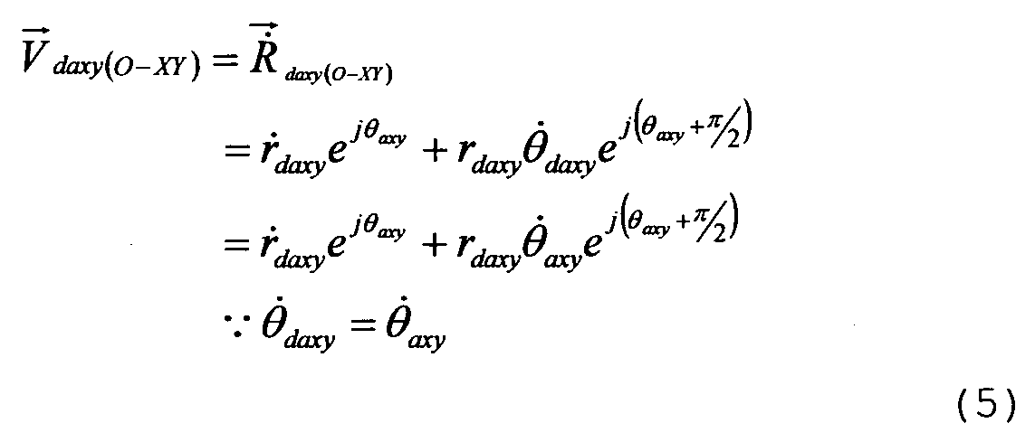
- a moving velocity at the imaging point D in the fixed coordinate system 0-XY is obtained by the following expression (5) .
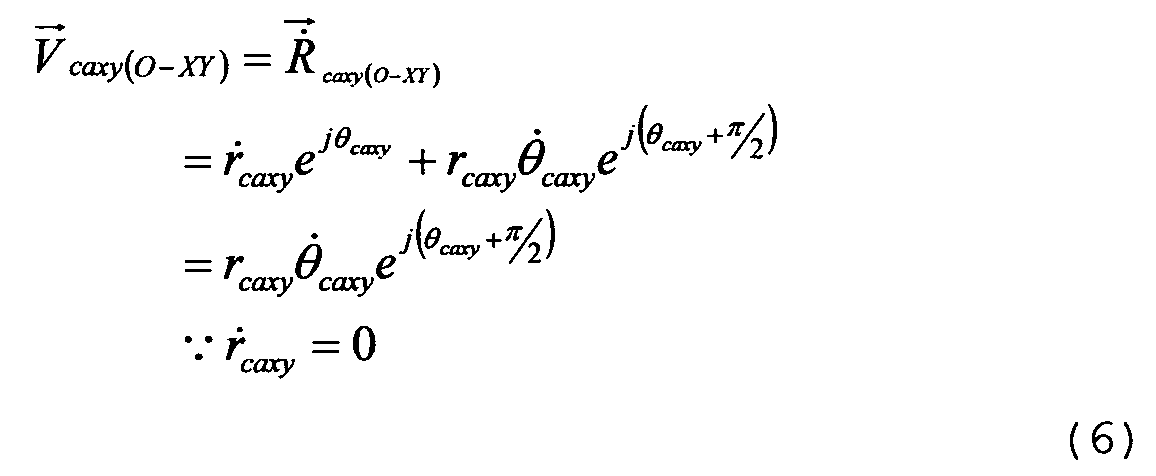
- the moving velocity of the image pickup device center C in the fixed coordinate system 0-XY is obtained by the following expression (6).
- the coordinate is converted from the fixed coordinate system O-XY into the moving coordinate system O2-X2Y2 fixed onto the camera.
- the expression is a strict expression strictly expressing the movement of the image which is actually recorded as an image.
- the imaginary part namely, the coordinate axis Y 2 direction component is the image movement component in the vertical direction of the camera within the image pickup surface.
- the real part of expression (12), namely, the coordinate axis X 2 direction component is the image movement component in the optical axis direction of the camera, and is a component by which a so-called blurred image occurs.
- the shake of the camera supported by the hand of a photographer is considered to be a vibration movement with a very small amplitude with a certain point in the space as the center, and therefore, the image movement velocity V dCXy(O2 - X1Y1) i- n tne moving coordinate system O2-X2Y2 which is strictly obtained is transformed into an approximate expression under the following conditions.
- V dCXy ( O1 - X2Y2 ) ' tne following expression ( 14 ) is derived .
- the approximate theoretical formula of the image movement velocity i n the moving coordinate system O 2 -X 2 Y 2 within the XY plane becomes the aforementioned expression (15).
- the component representing the direction of the image movement vector of the right side of expression (15) is , and therefore, the image movement direction is the Y 2 ⁇ axis direction in the direction at 90 degrees from the X 2 -axis.
- ⁇ represents an imaging magnification of this optical system
- f represents the actual focal length. (l+ ⁇ )f represents an image side focal length.
- this approximate expression means that the image movement velocity in the Y 2 direction within the image pickup surface is -(image side focal length) x (value obtained by subtracting the revolution angular velocity from the rotation angular velocity) .
- the image movement theoretical formula of the present invention in the two-dimensional ZX coordinate system when projected onto the ZX plane will be described.
- the approximate conditions are such that , .
- the approximate theoretical formula of the image movement velocity in the moving coordinate system O 2 -Z 2 X 2 within the ZY plane is as the following expression (16) by the procedure similar to the approximate formula V dcX y ( o2-x2Y2) in the XY plane.
- the component representing the direction of the image blur vector of the right side of expression (16) is , and therefore, the image movement direction is the Z 2 ⁇ axis direction in the direction at 90 degrees from the X 2 ⁇ axis.
- ⁇ represents the imaging magnification of this optical system
- f represents the actual focal length of this optical system.
- (l+ ⁇ )f represents the image side focal length. Therefore, the approximate formula means that the image movement velocity in the X 2 direction within the image pickup device surface is -(image side focal length) x (value obtained by subtracting the revolution angular velocity from the rotation angular velocity) .
- the output signal of the accelerometer 121 will be also described.
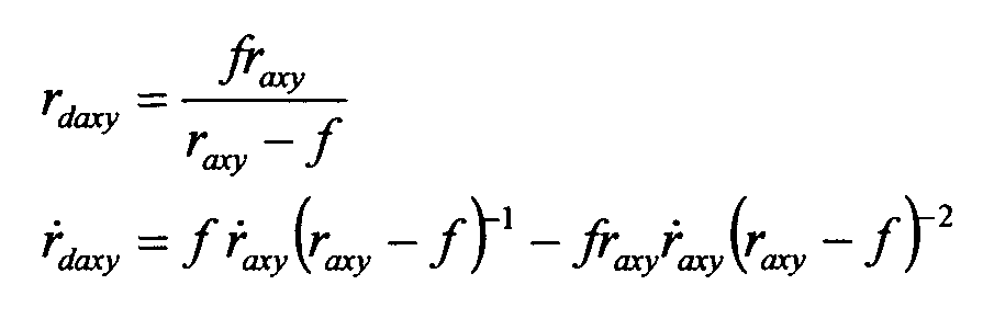
- the revolution angular velocity at the principal point A can be expressed as follows.
- the acceleration can be measured and calculated.
- the accelerometer 121 is fixed to the point B, and therefore, the acceleration value at the point A needs to be obtained by calculation based on the output of the accelerometer &t the point B.
- the difference value between the acceleration at the point B and that at the principal point A where the accelerometer is actually disposed, and the theoretical acceleration value at the point B are obtained.
- the component (term) which is unnecessary in image blur control is clarified.
- an acceleration vector which occurs at the principal point A in the fixed coordinate system O-XY is obtained from the following expression (17) .
- the relative acceleration vector a ⁇ the P°i n t B (accelerometer position) with respect to the point A in the fixed coordinate system 0-XY is obtained from the following expression (20) .
- the expression value is the movement vector error amount due to the fact that the accelerometer 121 is actually mounted at the position B with respect to the principal point A which is an ideal position.
- An acceleration a t the point B in the fixed coordinate system O-XY is expressed by the sum of the vectors from the origin O to the principal point A already obtained and from the principal point A to the point B.
- the position a ⁇ the point B in the fixed coordinate system O-XY is expressed by way of the principal point A by the following expression (21) .
- an acceleration a t the point B in the moving coordinate system will be calculated.
- the latitude (scalar) of the acceleration desired to be calculated is in the fixed coordinate system O-XYZ where the object is present.
- the acceleration is fixed to the moving coordinate system / the three axes of the accelerometer 121 are oriented in the X 2 -axis direction, the Y 2 ⁇ axis direction and the Z 2 -axis direction, and the acceleration component needs to be expressed by the coordinate axis directions of the moving coordinate system O 2 -X 2 Y 2- ⁇ .
- the disposition state of the accelerometer 121 will be described in detail.
- the accelerometer 121 of three- axis outputs is disposed at the point B.
- the axes of the accelerometer are set to an accelerometer output A CCX 2 with the sensitivity direction in the direction parallel with the X 2 ⁇ axis, an accelerometer output A ccy2 with the sensitivity direction in the direction parallel with the Y 2 -axis, and an accelerometer output A CCz2 with the sensitivity direction in the direction parallel with the Z 2 ⁇ axis. Since the movement in the XY plane is described here, the accelerometer output A ccx2 and the accelerometer output A ccy2 will be described.
- the approximate expression is obtained by substituting the approximate conditions. Restriction conditions are given such that the revolution angular velocity and the rotation angular velocity are very small vibration (+) around 0 so that
- This real part is the accelerometer output A ccx2 in the X 2 ⁇ axis direction
- the imaginary part is the accelerometer output A CCy2 in the Y 2 ⁇ axis direction.
- the above described polar coordinate system representation is decomposed into the X 2 component and the Y 2 component in the orthogonal coordinate system representation. Accelerometer output in the X 2 -axis direction:
- r axy is substantially equal to the object side focal length (l+ ⁇ )f/ ⁇ ( ⁇ represents an imaging magnification).
- the image pickup apparatus of recent years is equipped with the focus encoder which measures the moving position of the autofocus lens 140. Therefore, it is easy to calculate the object distance from the output value of the focus encoder, in the focus state. The result r axy is obtained.
- the value obtained from the next expression (27) is used as the revolution angular velocity . Accelerometer output in the Y 2 -axis direction:
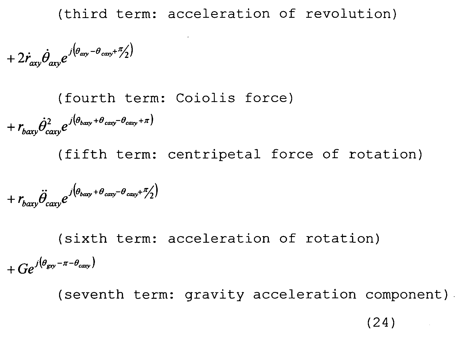
- the respective terms of the accelerometer output A ccy2 (o-x2Y2) in the Y 2 ⁇ axis direction will be described.
- the third term ⁇ s the component necessary for obtaining the revolution angular velocity desired to be obtained in the present embodiment, and the revolution angular velocity is obtained by dividing the third term with the known r axy and integrating the result.
- the fourth term represents a Coriolis force. If the movement of the camera in the optical axis direction is small, is established, and the fourth term can be ignored.
- the fifth term and the sixth term are the error components which are included in the accelerometer output A ccy 2(o- ⁇ 2Y2) since the accelerometer 121 cannot be disposed at the ideal principal point position A and is disposed at the point B.
- the fifth term represents the centripetal force which occurs since the accelerometer 121 rotates around the principal point A.
- r ba ⁇ y and ⁇ baxy are the coordinates of the point B at which the accelerometer 121 is mounted, and are known.
- the sixth term represents the acceleration component when the accelerometer 121 rotates around the principal point A, and rb a xy and ⁇ ba ⁇ y are the coordinates of the point B at which the accelerometer 121 is mounted, and are known. can be calculated by differentiating of the value of the angular velocity sensor
- the seventh term is the influence of the gravity acceleration, and can be dealt as the constant in the approximate expression, and therefore, can be erased by filtering processing of a circuit.
- X2Y 2 in the Y2 ⁇ axis direction includes unnecessary components for revolution angular velocity which is desired to be obtained in the present invention.
- the accelerometer 121 it has become clear that by disposing the accelerometer 121 at the position where the unnecessary components become the minimum, the necessary revolution angular velocity can be obtained without correction calculation.
- the movement velocity in the substantially optical axis direction of the camera is desired to be calculated.
- the first term r ⁇ corresponds to the optical axis direction movement acceleration.
- the second term, the fifth term, the sixth term and the seventh term can be erased for the same reason as described with the accelerometer output A CC y 2 (o-x2Y2) in the Y2 ⁇ axis direction.
- the accelerometer 121 by similarly disposing the accelerometer 121 at the position where the unnecessary components become the minimum, the movement velocity substantially in the optical axis direction of the camera can be obtained from the accelerometer output A ccx2 (o-x2Y2) in the X2 direction without correction calculation.
- the revolution angular velocity in real time is estimated by multiplying the ratio of the revolution angular velocity to the past rotation angular velocity by the rotation angular velocity in real time.
- the closest proximity is set to an equal- magnification, but the closest proximity is not limited to this, because even if the closest proximity is, for example, twice according to the specifications of the shooting optical system to which the present invention is applied, the sum of products of the error ratio function corresponding to each shooting imaging magnification is obtained between the shooting imaging magnification of twice to 0.0, whereby the position of the accelerometer 121 where the error components become the minimum can be obtained. Therefore, it is obvious that the effect of the content described in the present embodiment does not change irrespective of the shooting imaging magnification of the closest proximity of the shooting optical system.
- an angular movement and a parallel movement are newly and strictly modeled and expressed mathematically to be a rotation movement and a revolution movement, and thereby, in whatever state the two movement component states are, accurate image stabilization without a control failure can be performed.
- the accelerometer is disposed at the position where the error amount accompanying the change of the principal point position of the shooting optical system becomes the minimum, and therefore, accurate image stabilization corresponding to the change of the principal point position of the shooting optical system can be performed.
- image stabilization is performed with the difference between the rotation angular velocity and the revolution angular velocity, and therefore, the calculation processing amount after difference calculation can be reduced.
- the units of the rotation movement and the revolution movement are the same (for example: rad/sec) , and therefore, calculation becomes easy.
- the image movement in the image pickup surface of the image pickup device, and the optical axis direction movement can be represented by the same expression, and therefore, image movement correction calculation and the optical axis direction movement correction calculation can be performed at the same time.
- the error ratio at each shooting imaging magnification is obtained by using expression (33), and from the result of the sum of products of the value, the position of the accelerometer 121 where the error ratio becomes the minimum is obtained.
- the error ratio at each shooting imaging magnification obtained by using expression (33) is multiplied by a shooting frequency to weight.
- FIG. 19A the shooting frequency at each shooting imaging magnification known as a result of the earnest study of the present applicant is multiplied.
- the shooting frequency is illustrated in FIG. 19A
- FIG. 20 illustrates how the result of integrating the value at each shooting imaging magnification of (error ratio) x (shooting frequency) which is obtained as shown in FIG. 19B changes when the accelerometer 121 is disposed at each shooting imaging magnification. As shown in FIG.
- the case where the error ratio function at each shooting imaging magnification obtained by using expression (33) is weighted by the effective amount of a parallel movement at each shooting imaging magnification is considered.
- FIG. 21 illustrates how the result of integrating the value at each shooting imaging magnification of (error ratio) x (parallel movement effective amount) changes when the accelerometer 121 is disposed at each shooting imaging magnification.
- the accelerometer 121 can be disposed at the minimum position which is more suitable for the use of the camera of a photographer. It goes without saying that by weighting the error ratio with the value obtained by multiplying the shooting frequency and the effective amount of a parallel movement, the accelerometer 121 also can be disposed at the position where the error ratio is the minimum.
- FIGS. 22A and 22B By using FIGS. 22A and 22B, embodiment 3 will be described. The same flow as in FIGS. 7A and 7B according to embodiment 1 is included. Therefore, the same reference numerals and characters are used for the same flow, and the description will be omitted. After revolution angular velocity calculation of
- the flow proceeds to S2610.
- S2610 it is determined whether the imaging magnification of shooting is 0.2 or more (predetermined value or more) . In the case of 0.2 or more, the flow proceeds to S2620, and in the case of less than 0.2 (less than the predetermined value), the flow proceeds to S1130.
- S1130 rotation movement correction calculation is performed as in embodiment 1.
- the angular velocity ratio is fixed (stored) to the constant (specified constant) of 0.9, and in the next S2640, estimation of the present revolution angular velocity is calculated by multiplying the rotation angular velocity obtained in real time by the constant angular velocity ratio of 0.9, and the flow proceeds to the next S1120.
- the rotation revolution difference movement correction calculation is performed as in embodiment 1.
- the revolution angular velocity is sufficiently small with respect to the rotation angular velocity, and therefore, the image stabilization calculation is simplified by only performing rotation movement correction, which leads to enhancement in speed and reduction in power consumption. Further, the ratio of the revolution angular velocity to the rotation angular velocity rarely exceeds one, and when the ratio exceeds
Abstract
Description


Claims
Priority Applications (6)
| Application Number | Priority Date | Filing Date | Title |
|---|---|---|---|
| EP10786016.5A EP2440970B1 (en) | 2009-06-11 | 2010-04-23 | Image stabilization apparatus and image pickup apparatus |
| CN201080026072.3A CN102804053B (en) | 2009-06-11 | 2010-04-23 | Image stabilization apparatus and image pickup apparatus |
| KR1020127000294A KR101287931B1 (en) | 2009-06-11 | 2010-04-23 | Image stabilization apparatus and image pickup apparatus |
| US13/263,465 US8711272B2 (en) | 2009-06-11 | 2010-04-23 | Image stabilization apparatus and image pickup apparatus |
| RU2012100254/28A RU2498376C2 (en) | 2009-06-11 | 2010-04-23 | Image stabilising device and image capturing device |
| BRPI1013048-9A BRPI1013048B1 (en) | 2009-06-11 | 2010-04-23 | IMAGE STABILIZATION AND IMAGE CAPTURE APPARATUS |
Applications Claiming Priority (2)
| Application Number | Priority Date | Filing Date | Title |
|---|---|---|---|
| JP2009140255A JP4857363B2 (en) | 2009-06-11 | 2009-06-11 | Image shake correction apparatus and imaging apparatus |
| JP2009-140255 | 2009-06-11 |
Publications (1)
| Publication Number | Publication Date |
|---|---|
| WO2010143485A1 true WO2010143485A1 (en) | 2010-12-16 |
Family
ID=43308745
Family Applications (1)
| Application Number | Title | Priority Date | Filing Date |
|---|---|---|---|
| PCT/JP2010/057729 WO2010143485A1 (en) | 2009-06-11 | 2010-04-23 | Image stabilization apparatus and image pickup apparatus |
Country Status (8)
| Country | Link |
|---|---|
| US (1) | US8711272B2 (en) |
| EP (1) | EP2440970B1 (en) |
| JP (1) | JP4857363B2 (en) |
| KR (1) | KR101287931B1 (en) |
| CN (1) | CN102804053B (en) |
| BR (1) | BRPI1013048B1 (en) |
| RU (1) | RU2498376C2 (en) |
| WO (1) | WO2010143485A1 (en) |
Cited By (1)
| Publication number | Priority date | Publication date | Assignee | Title |
|---|---|---|---|---|
| CN109844632A (en) * | 2016-10-13 | 2019-06-04 | 富士胶片株式会社 | Shake correction device, photographic device and method of compensating for hand shake |
Families Citing this family (16)
| Publication number | Priority date | Publication date | Assignee | Title |
|---|---|---|---|---|
| JP2013017165A (en) | 2011-06-10 | 2013-01-24 | Panasonic Corp | Imaging apparatus |
| GB2508471B (en) * | 2012-11-29 | 2015-10-07 | Cooke Optics Ltd | Camera lens assembly |
| US9563105B1 (en) * | 2013-04-10 | 2017-02-07 | Ic Real Tech Inc. | Screw coupler enabling direct secure fastening between communicating electronic components |
| TW201442512A (en) * | 2013-04-19 | 2014-11-01 | Hon Hai Prec Ind Co Ltd | Auto-focus design system, electronic device having the same, and auto-focus design method |
| JP6023999B2 (en) * | 2013-04-25 | 2016-11-09 | 多摩川精機株式会社 | Space stabilizer |
| JP2015034879A (en) * | 2013-08-08 | 2015-02-19 | キヤノン株式会社 | Image shake correction device and control method for the same, lens barrel, optical device and imaging device |
| JP6410431B2 (en) * | 2014-01-30 | 2018-10-24 | オリンパス株式会社 | Camera system |
| CN104792500B (en) * | 2015-04-20 | 2017-07-14 | 中国科学院上海光学精密机械研究所 | The diagnostic method of optical system light beam pointing stability |
| US11202011B2 (en) * | 2016-07-25 | 2021-12-14 | Canon Kabushiki Kaisha | Control apparatus, image capturing apparatus, lens apparatus, image capturing system, control method, and storage medium |
| JP7057628B2 (en) * | 2017-01-26 | 2022-04-20 | Omデジタルソリューションズ株式会社 | Image pickup device and its image blur calculation method |
| JP6582153B2 (en) * | 2017-03-15 | 2019-09-25 | 富士フイルム株式会社 | Imaging apparatus, imaging method, and imaging program |
| WO2018230316A1 (en) * | 2017-06-12 | 2018-12-20 | 富士フイルム株式会社 | Shake detection device, image-capturing device, lens device, image capturing device body, shake detection method, and shake detection program |
| JP7086571B2 (en) * | 2017-11-16 | 2022-06-20 | キヤノン株式会社 | Image pickup device, lens device and control method thereof |
| JP6960324B2 (en) * | 2017-12-19 | 2021-11-05 | 旭化成エレクトロニクス株式会社 | Blur amount calculation device, blur amount correction device, image pickup device, method, and program |
| US11539887B2 (en) | 2018-03-23 | 2022-12-27 | Huawei Technologies Co., Ltd. | Video image anti-shake method and terminal |
| CH716570A2 (en) * | 2019-09-09 | 2021-03-15 | Andre Reber | Method for improving the eyesight of a visually impaired person with a portable visual aid. |
Citations (5)
| Publication number | Priority date | Publication date | Assignee | Title |
|---|---|---|---|---|
| JPS62153816A (en) * | 1985-12-26 | 1987-07-08 | Canon Inc | Image moving mechanism |
| JP2006091279A (en) * | 2004-09-22 | 2006-04-06 | Canon Inc | Optical instrument |
| JP2006208691A (en) * | 2005-01-27 | 2006-08-10 | Canon Inc | Imaging apparatus, its camera main body, and interchangeable lens |
| JP2007034141A (en) * | 2005-07-29 | 2007-02-08 | Olympus Imaging Corp | Camera system and lens unit |
| JP2007171786A (en) * | 2005-12-26 | 2007-07-05 | Canon Inc | Vibration-proof control device and imaging apparatus |
Family Cites Families (19)
| Publication number | Priority date | Publication date | Assignee | Title |
|---|---|---|---|---|
| DE3628480A1 (en) * | 1985-08-23 | 1987-03-05 | Canon Kk | Method and device for compensating a movement of an image |
| JP3103572B2 (en) | 1990-01-16 | 2000-10-30 | オリンパス光学工業株式会社 | Camera device |
| EP0843201A1 (en) | 1992-07-15 | 1998-05-20 | Nikon Corporation | Image-shake correcting photographic apparatus |
| JP3513950B2 (en) | 1993-12-14 | 2004-03-31 | 株式会社ニコン | Image stabilization camera |
| JPH07301839A (en) * | 1994-05-10 | 1995-11-14 | Olympus Optical Co Ltd | Camera shake correcting device |
| RU2095839C1 (en) * | 1995-04-12 | 1997-11-10 | Акционерное общество закрытого типа "Наутэк-холдинг" | Device stabilizing optical image |
| US5794078A (en) * | 1995-09-11 | 1998-08-11 | Nikon Corporation | Image movement correction of camera |
| US6429895B1 (en) * | 1996-12-27 | 2002-08-06 | Canon Kabushiki Kaisha | Image sensing apparatus and method capable of merging function for obtaining high-precision image by synthesizing images and image stabilization function |
| JPH11249185A (en) * | 1998-03-04 | 1999-09-17 | Nikon Corp | Camera system and interchangeable lens |
| JP2004295027A (en) | 2003-03-28 | 2004-10-21 | Nikon Corp | Blurring correction device |
| JP4717382B2 (en) * | 2004-06-15 | 2011-07-06 | キヤノン株式会社 | Optical equipment |
| WO2007141986A1 (en) * | 2006-05-26 | 2007-12-13 | Victor Company Of Japan, Limited | Image blurring correction device |
| JP4827662B2 (en) * | 2006-08-31 | 2011-11-30 | Hoya株式会社 | Camera with focus adjustment device |
| JP4400611B2 (en) * | 2006-10-26 | 2010-01-20 | カシオ計算機株式会社 | Imaging apparatus, blur correction method, and program |
| JP2009105784A (en) * | 2007-10-25 | 2009-05-14 | Sony Corp | Imaging apparatus |
| JP4876066B2 (en) * | 2007-12-19 | 2012-02-15 | キヤノン株式会社 | Video processing apparatus, video processing system, video processing method, and program |
| JP5430074B2 (en) * | 2008-04-03 | 2014-02-26 | キヤノン株式会社 | Optical apparatus and imaging apparatus including the same |
| JP2009290863A (en) * | 2008-04-28 | 2009-12-10 | Panasonic Corp | Imaging apparatus, and camera body |
| KR20100085728A (en) * | 2009-01-21 | 2010-07-29 | 삼성전자주식회사 | Photographing apparatus and focus detecting method using the same |
-
2009
- 2009-06-11 JP JP2009140255A patent/JP4857363B2/en not_active Expired - Fee Related
-
2010
- 2010-04-23 RU RU2012100254/28A patent/RU2498376C2/en not_active IP Right Cessation
- 2010-04-23 BR BRPI1013048-9A patent/BRPI1013048B1/en not_active IP Right Cessation
- 2010-04-23 CN CN201080026072.3A patent/CN102804053B/en not_active Expired - Fee Related
- 2010-04-23 US US13/263,465 patent/US8711272B2/en not_active Expired - Fee Related
- 2010-04-23 KR KR1020127000294A patent/KR101287931B1/en active IP Right Grant
- 2010-04-23 EP EP10786016.5A patent/EP2440970B1/en not_active Not-in-force
- 2010-04-23 WO PCT/JP2010/057729 patent/WO2010143485A1/en active Application Filing
Patent Citations (5)
| Publication number | Priority date | Publication date | Assignee | Title |
|---|---|---|---|---|
| JPS62153816A (en) * | 1985-12-26 | 1987-07-08 | Canon Inc | Image moving mechanism |
| JP2006091279A (en) * | 2004-09-22 | 2006-04-06 | Canon Inc | Optical instrument |
| JP2006208691A (en) * | 2005-01-27 | 2006-08-10 | Canon Inc | Imaging apparatus, its camera main body, and interchangeable lens |
| JP2007034141A (en) * | 2005-07-29 | 2007-02-08 | Olympus Imaging Corp | Camera system and lens unit |
| JP2007171786A (en) * | 2005-12-26 | 2007-07-05 | Canon Inc | Vibration-proof control device and imaging apparatus |
Non-Patent Citations (1)
| Title |
|---|
| See also references of EP2440970A4 * |
Cited By (3)
| Publication number | Priority date | Publication date | Assignee | Title |
|---|---|---|---|---|
| CN109844632A (en) * | 2016-10-13 | 2019-06-04 | 富士胶片株式会社 | Shake correction device, photographic device and method of compensating for hand shake |
| US10827124B2 (en) | 2016-10-13 | 2020-11-03 | Fujifilm Corporation | Shake correction device, imaging apparatus, and shake correction method |
| CN109844632B (en) * | 2016-10-13 | 2021-03-12 | 富士胶片株式会社 | Image stabilization device, imaging device, and image stabilization method |
Also Published As
| Publication number | Publication date |
|---|---|
| KR101287931B1 (en) | 2013-07-19 |
| BRPI1013048A2 (en) | 2016-04-05 |
| JP4857363B2 (en) | 2012-01-18 |
| EP2440970A1 (en) | 2012-04-18 |
| CN102804053B (en) | 2015-06-10 |
| CN102804053A (en) | 2012-11-28 |
| EP2440970A4 (en) | 2012-05-16 |
| EP2440970B1 (en) | 2013-10-23 |
| BRPI1013048B1 (en) | 2020-07-28 |
| US20120038783A1 (en) | 2012-02-16 |
| US8711272B2 (en) | 2014-04-29 |
| RU2012100254A (en) | 2013-07-20 |
| RU2498376C2 (en) | 2013-11-10 |
| KR20120025586A (en) | 2012-03-15 |
| JP2010286651A (en) | 2010-12-24 |
Similar Documents
| Publication | Publication Date | Title |
|---|---|---|
| EP2440970B1 (en) | Image stabilization apparatus and image pickup apparatus | |
| US8339466B2 (en) | Image stabilization apparatus and image pickup apparatus | |
| JP5284169B2 (en) | Image shake correction apparatus, optical apparatus including the same, and imaging apparatus | |
| CN105814484B (en) | Shake correction device and adjustment method thereof, shake correction circuit, shake correction method, and camera module and position control method of optical element thereof | |
| US8514290B2 (en) | Camera-shake correction apparatus and imaging apparatus including the same | |
| CN102455567A (en) | Optical apparatus, image capturing apparatus, and method for controlling optical apparatus | |
| JP2009300614A (en) | Imaging device | |
| JP2006300997A (en) | Imaging apparatus with image blur preventing function | |
| JP2004295027A (en) | Blurring correction device | |
| JP5164410B2 (en) | Imaging device | |
| JP5822548B2 (en) | Image blur correction apparatus, image blur correction method, and imaging apparatus | |
| JP2009069618A (en) | Imaging apparatus, control program, and record medium | |
| JP2014228623A (en) | Camera-shake correcting device, lens barrel, and photographing apparatus | |
| JP5854653B2 (en) | Anti-shake control device, imaging device, and anti-shake control method | |
| JP2010231037A (en) | Camera system and optical instrument | |
| US10924672B2 (en) | Camera controller | |
| JP2007065117A (en) | Image blur correction device | |
| JP2015028547A (en) | Imaging apparatus | |
| JP2013162185A (en) | Optical instrument and imaging apparatus | |
| JP2007096411A (en) | Imaging apparatus |
Legal Events
| Date | Code | Title | Description |
|---|---|---|---|
| WWE | Wipo information: entry into national phase |
Ref document number: 201080026072.3 Country of ref document: CN |
|
| 121 | Ep: the epo has been informed by wipo that ep was designated in this application |
Ref document number: 10786016 Country of ref document: EP Kind code of ref document: A1 |
|
| WWE | Wipo information: entry into national phase |
Ref document number: 13263465 Country of ref document: US |
|
| WWE | Wipo information: entry into national phase |
Ref document number: 2010786016 Country of ref document: EP |
|
| NENP | Non-entry into the national phase |
Ref country code: DE |
|
| ENP | Entry into the national phase |
Ref document number: 20127000294 Country of ref document: KR Kind code of ref document: A |
|
| WWE | Wipo information: entry into national phase |
Ref document number: 281/CHENP/2012 Country of ref document: IN |
|
| WWE | Wipo information: entry into national phase |
Ref document number: 2012100254 Country of ref document: RU |
|
| REG | Reference to national code |
Ref country code: BR Ref legal event code: B01A Ref document number: PI1013048 Country of ref document: BR |
|
| ENP | Entry into the national phase |
Ref document number: PI1013048 Country of ref document: BR Kind code of ref document: A2 Effective date: 20111209 |