JP2009300614A - Imaging device - Google Patents
Imaging device Download PDFInfo
- Publication number
- JP2009300614A JP2009300614A JP2008153401A JP2008153401A JP2009300614A JP 2009300614 A JP2009300614 A JP 2009300614A JP 2008153401 A JP2008153401 A JP 2008153401A JP 2008153401 A JP2008153401 A JP 2008153401A JP 2009300614 A JP2009300614 A JP 2009300614A
- Authority
- JP
- Japan
- Prior art keywords
- shake correction
- shake
- correction gain
- setting
- gain
- Prior art date
- Legal status (The legal status is an assumption and is not a legal conclusion. Google has not performed a legal analysis and makes no representation as to the accuracy of the status listed.)
- Pending
Links
Images


Classifications
-
- H—ELECTRICITY
- H04—ELECTRIC COMMUNICATION TECHNIQUE
- H04N—PICTORIAL COMMUNICATION, e.g. TELEVISION
- H04N23/00—Cameras or camera modules comprising electronic image sensors; Control thereof
- H04N23/60—Control of cameras or camera modules
- H04N23/68—Control of cameras or camera modules for stable pick-up of the scene, e.g. compensating for camera body vibrations
Landscapes
- Engineering & Computer Science (AREA)
- Multimedia (AREA)
- Signal Processing (AREA)
- Studio Devices (AREA)
- Adjustment Of Camera Lenses (AREA)
Abstract
Description
本発明は、手振れ等の振れによる像振れを補正する機能を有する撮像装置に関するものである。 The present invention relates to an imaging apparatus having a function of correcting image blur due to camera shake or the like.
デジタルカメラ、ビデオカメラ等の撮像装置では、手振れ等の振れにより被写体像が振れてしまい、見づらい映像となってしまうことがよくある。最近では高倍率のレンズが採用されており、特にテレ(望遠)側の時は振れが大きく目立つ。このような手振れ等の振れによるに像振れを補正する機能を備えた撮像装置が数多く提案され、製品化されている。 In an imaging device such as a digital camera or a video camera, a subject image often shakes due to a shake such as a hand shake, and the image is often difficult to see. Recently, a high-magnification lens has been adopted, and the shake is particularly noticeable especially on the telephoto side. Many image pickup apparatuses having a function of correcting image shake due to such shakes as camera shake have been proposed and commercialized.
手振れ等の振れを検出するための方式には、例えば手振れによる撮像装置の振れを振れセンサによって検出するセンサ方式と、撮影した画像に基づいて振れを検出する動きベクトル方式がある。センサ方式では、角速度センサがよく用いられる。この角速度センサは、圧電素子等の振動材を一定周波数で振動させ、回転運動成分により発生するコリオリの力を電圧に変換して角速度情報を得る。得られた角速度情報に対して積分を行い、振れ出力から補正位置制御信号(振れ補正量)を算出し、該補正位置制御信号により光学的に画角を移動可能な補正手段である補正レンズ(もしくは撮像素子)を駆動することで像振れ補正を行っている。 As a method for detecting shake such as hand shake, there are, for example, a sensor method that detects a shake of an imaging apparatus due to a shake by a shake sensor and a motion vector method that detects a shake based on a photographed image. In the sensor system, an angular velocity sensor is often used. This angular velocity sensor vibrates a vibration material such as a piezoelectric element at a constant frequency, converts Coriolis force generated by a rotational motion component into a voltage, and obtains angular velocity information. The obtained angular velocity information is integrated, a correction position control signal (shake correction amount) is calculated from the shake output, and a correction lens (correction means that can optically move the angle of view by the correction position control signal) Alternatively, image blur correction is performed by driving an image pickup device.
一方、動きベクトル方式は、撮像レンズを介して投影される被写体の画像を撮像素子で検出し、画像信号としてメモリに記憶しておき、次に検出する画像信号と比較して画像の振れを動きベクトルとして算出する。算出された動きベクトルから補正位置制御信号を算出し、該補正位置制御信号により光学的に画角を移動可能な補正手段である補正レンズ(もしくは撮像素子)を駆動することで像振れ補正を行っている。なお、像振れ補正のための例えば補正レンズ駆動時には、いずれの方式においても、上記補正位置制御信号に補正レンズ位置信号をフィードバックさせるフィードバック制御が行われる。 On the other hand, in the motion vector method, an image of a subject projected through an imaging lens is detected by an imaging device, stored in a memory as an image signal, and the shake of the image is compared with the next detected image signal. Calculate as a vector. A correction position control signal is calculated from the calculated motion vector, and image blur correction is performed by driving a correction lens (or an image sensor) that is a correction means that can optically move the angle of view by the correction position control signal. ing. For example, when driving a correction lens for image blur correction, feedback control for feeding back the correction lens position signal to the correction position control signal is performed in any method.
上記した振れセンサや撮影した画像信号から得られる振れ出力から算出される補正位置制御信号に基づいて像振れを補正する方法や装置などは数多く提案されている。例えば、振れセンサの検出された手振れ信号をもとに生成される振れ出力と、動きベクトル検出部で検出された動きベクトルをもとに生成される振れ出力とに基づいてゲイン調整値係数を算出する。そして、振れセンサの振れ出力に上記ゲイン調整値係数に基づいて設定される振れ補正ゲインをかけることにより、像振れ補正機能の効果を高めるという技術が提案されている(特許文献1)。なお、振れ補正ゲインとは、振れセンサの個体差のばらつきや環境変化、経時変化などによる出力変化を調整し、振れセンサの振れ出力が所定の手振れに対して一定の値を示すようにするためのものである。 Many methods and apparatuses for correcting image blur based on the above-described shake sensor and a corrected position control signal calculated from a shake output obtained from a photographed image signal have been proposed. For example, the gain adjustment value coefficient is calculated based on the shake output generated based on the shake signal detected by the shake sensor and the shake output generated based on the motion vector detected by the motion vector detection unit. To do. A technique for enhancing the effect of the image blur correction function by applying a shake correction gain set based on the gain adjustment value coefficient to the shake output of the shake sensor has been proposed (Patent Document 1). The shake correction gain is used to adjust the output change due to variations in individual differences of shake sensors, environmental changes, changes over time, etc., so that the shake output of the shake sensor shows a constant value for a given hand shake. belongs to.
また、撮像装置の小型化によって撮像レンズなどの光学系も小型化され、撮影可能な画角範囲も制約が大きくなってきている。そのため、広角な画像あるいは、より遠くの画像を撮影するため、撮像レンズの倍率を変換するコンバージョンレンズを取り付ける機会も増えてきている。
しかしながら、上記従来例では、動く被写体を撮影する際に被写体振れを含んだ動きベクトルに基づいてゲイン調整値係数を算出すると、適切な振れ補正ゲインが得られず、撮影された画像において十分な像振れ補正効果を得られないという問題があった。 However, in the above conventional example, when a gain adjustment value coefficient is calculated based on a motion vector including subject shake when a moving subject is photographed, an appropriate shake correction gain cannot be obtained, and a sufficient image is obtained in the photographed image. There was a problem that the shake correction effect could not be obtained.
また、撮像装置に対してパンニング動作を行った際にゲイン調整値係数を算出すると、パンニング動作中およびパンニング動作終了直後においては適切な振れ補正ゲインが得られない。このため、パンニング動作中およびパンニング動作終了直後において撮影された画像においては十分な像振れ補正効果を得ることができないという問題があった。 In addition, if the gain adjustment value coefficient is calculated when the panning operation is performed on the imaging apparatus, an appropriate shake correction gain cannot be obtained during the panning operation and immediately after the panning operation ends. For this reason, there has been a problem that a sufficient image blur correction effect cannot be obtained in images taken during the panning operation and immediately after the end of the panning operation.
さらに、上記従来例では、振れ補正ゲインを設定した後も該振れ補正ゲインに変化が生じるような場合のみならず、常に該振れ補正ゲインの設定のための演算を行っているため、演算処理部に不必要な演算負荷を与えるものであった。 Furthermore, in the above conventional example, not only when the shake correction gain changes even after the shake correction gain is set, but the calculation for setting the shake correction gain is always performed. Would give unnecessary computation load.
(発明の目的)
本発明の目的は、常に適切な振れ補正ゲインを設定するとともに、該振れ補正ゲイン設定のための演算負荷を軽減することのできる撮像装置を提供しようとするものである。
(Object of invention)
An object of the present invention is to provide an imaging apparatus capable of always setting an appropriate shake correction gain and reducing the calculation load for setting the shake correction gain.
上記目的を達成するために、本発明は、振れを検出する振れ検出手段と、撮像手段にて取り込んだ画像信号から動きベクトルを検出する動きベクトル検出手段と、前記振れ検出手段の振れ出力に基づいて前記振れを補正する振れ補正量を算出する振れ補正量算出手段と、前記振れ検出手段の振れ出力と前記動きべクトルを用いて前記振れ補正量の算出に用いられる振れ補正ゲインを設定する振れ補正ゲイン設定手段と、前記振れ補正量により補正手段を駆動し、前記振れによる像振れを補正する制御手段とを有する撮像装置において、撮影状態の変化に応じて前記振れ補正ゲインの設定開始と停止を制御する振れ補正ゲイン制御手段を有する撮像装置とするものである。 To achieve the above object, the present invention is based on shake detection means for detecting shake, motion vector detection means for detecting a motion vector from an image signal captured by an imaging means, and a shake output of the shake detection means. A shake correction amount calculating unit for calculating a shake correction amount for correcting the shake, and a shake correction gain used for calculating the shake correction amount using the shake output and the motion vector of the shake detection unit. In an imaging apparatus having a correction gain setting means and a control means for driving the correction means according to the shake correction amount and correcting image shake due to the shake, setting start and stop of the shake correction gain according to a change in shooting state The image pickup apparatus has a shake correction gain control means for controlling the image.
以上説明したように、本発明によれば、常に適切な振れ補正ゲインを設定するとともに、該振れ補正ゲイン設定のための演算負荷を軽減することができる撮像装置を提供できるものである。 As described above, according to the present invention, it is possible to provide an imaging apparatus capable of always setting an appropriate shake correction gain and reducing the calculation load for setting the shake correction gain.
本発明を実施するための最良の形態は、以下の実施例1ないし3に示す通りである。 The best mode for carrying out the present invention is as shown in Examples 1 to 3 below.
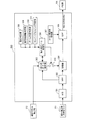
図1は本発明の実施例1に係る撮像装置全体の概略を示す構成図である。図1において、101は変倍を行うズームレンズをもつズームユニット、102はズームユニット101を駆動制御するズーム駆動制御部である。103は画角変更(像振れ補正)を可能とする補正レンズであるシフトレンズ(ユニット)、104はシフトレンズ103を駆動制御するシフトレンズ駆動制御部である。106は絞り・シャッタユニット105を駆動制御する絞り・シャッタ制御部である。107はピント調節を行うレンズを持つフォーカスユニット、108はフォーカスユニット107を駆動制御するフォーカス駆動制御部である。
FIG. 1 is a configuration diagram illustrating an outline of the entire imaging apparatus according to the first embodiment of the present invention. In FIG. 1,
109は各レンズ群を通ってきた光像を電気信号に変換する撮像部、110は撮像部109からの電気信号を映像信号に変換処理する撮像信号処理部である。111は撮像信号処理部110からの映像信号を用途に応じて加工する映像信号処理部、112は映像信号処理部111からの信号を必要に応じて表示する表示部である。
An
113はシステム全体で使用する用途に応じた電源を供給する電源部、114は外部との通信及び映像信号の入出力を行う外部入出力端子部である。115はシステムを操作するための操作部、116は映像情報など様々なデータを記憶する記憶部、117はシステム全体を制御する制御部である。
次に、上記構成の撮像装置の全体システムについて説明する。 Next, the entire system of the imaging apparatus having the above configuration will be described.
操作部115は押し込み量に応じて第1スイッチ(SW1)および第2スイッチ(SW2)が順にオンするように構成されたシャッタレリーズボタンを有している。詳しくは、シャッタレリーズボタンが約半分押し込まれたときに第1スイッチがオンし、シャッタレリーズボタンが最後まで押し込まれたときに第2スイッチがオンする構造となっている。
The
第1スイッチがオンすると、フォーカスユニット107によりピント調節が行われるとともに、絞り・シャッタユニット105により適正な露光量が設定される。さらに第2スイッチがオンすると、撮像部109に被写体像が露光され、ここで得られた画像情報が記憶部116に記憶される。
When the first switch is turned on, focus adjustment is performed by the
また、操作部115に含まれる振れ補正スイッチにより振れ補正の指示がなされると、制御部117がシフトレンズ駆動制御部104に像振れ補正を指示する。これにより、像振れ補正の停止指示がなされるまでシフトレンズ103が光軸と直交する平面内で移動させられ、像振れ補正が行われる。また、静止画モードと動画モードを選択可能としており、それぞれのモードにおいて各アクチュエータの動作条件も変更可能となっている。
When a shake correction instruction is given by a shake correction switch included in the
また、操作部115に含まれるズームスイッチによりズームの指示があると、制御部117が、ズーム駆動制御部102を介して、指示されたズーム位置にズームユニット101を移動させる。また、撮像部109から撮像信号処理部110、映像信号処理部111にて処理された画像情報をもとにフォーカス駆動制御部108を介してフォーカスレンズ107を駆動させ、ピント調節を行わせる。
Further, when there is an instruction for zooming with the zoom switch included in the
図2は、図1に示したシフトレンズ駆動制御部104の構成を示すブロック図である。
FIG. 2 is a block diagram showing a configuration of the shift lens
図2において、201は撮像装置の正位置状態におけるピッチ方向(垂直方向)の手振れ等の振れを検出するピッチ方向振れ検出部、202は撮像装置の正位置状態におけるヨー方向(水平方向)の手振れ等の振れを検出するヨー方向振れ検出部である。203,204は防振制御部であり、撮像部211からの画像信号をもとに動きベクトル検出部212にて検出された動きベクトルと振れ検出部201,202からの振れ出力をもとにシフトレンズ103の駆動目標位置を指示する補正位置制御信号を生成する。なお、撮像部211は図1の撮像部109に対応する。
In FIG. 2,
205,206はピッチ方向、ヨー方向それぞれの補正位置制御信号と後述のシフトレンズ位置信号の差が0になるように駆動制御するPID部である。207,208はPID部205,206からの信号をもとにシフトレンズ103を駆動するドライブ部である。209はシフトレンズ103のピッチ方向の位置を検出してシフトレンズ位置信号を出力する位置検出部、210はシフトレンズ103のヨー方向の位置を検出してシフトレンズ位置信号を出力する位置検出部である。
なお、防振制御部203,204および動きベクトル検出部212が図1の制御部117に含まれ、PID部205,206、ドライブ部207,208および位置検出部209,210が図1のシフトレンズ駆動制御部104に含まれる。
The image
次に、像振れ補正(防振)動作について説明する。 Next, an image blur correction (anti-shake) operation will be described.
像振れ補正動作は、振れ検出部201,202からの振れ出力および動きベクトル検出部212からの振れ出力(動きベクト)に基づいて、防振制御部203,204およびシフレンズ駆動制御部104がシフトレンズ103を駆動することで行われる。詳しくは、上記各振れ出力に基づいて防振制御部203,204が補正位置制御信号(駆動目標値=振れ補正量)を算出する。そして、該補正位置制御信号とシフトレンズ位置信号に基づいてシフトレンズ駆動制御部104がシフトレンズ103を駆動することで行われる。
In the image blur correction operation, the image
上記シフトレンズ103の駆動時に、該シフトレンズ103の位置制御が行われている。詳しくは、シフトレンズ103に取り付けられた磁石の位置検出が位置検出部209,210であるホール素子により磁石の磁束を検知することで行われる。そして、シフトレンズ103の位置信号であるホール素子出力を防振制御部203,204からの振れ補正量に合わせるようなフィードバック位置制御が行われる。なお、位置検出部209,210のホール素子出力には個体ばらつきがあるため、所定の振れ量に対して、シフトレンズ103が所定位置に移動するようにホール素子出力の調整を行う必要がある。このとき、PID部205,206では比例制御(P制御)と積分制御(I制御)と微分制御(D制御)を用いたPID制御を行う。そして、ドライブ部207,208にPID制御信号が出力される。
When the
図3は、図2の防振制御部213の構成を示すブロック図であり、振れセンサ201として角速度センサを使用した例を示す。なお、防振制御部214も同様の構成であり、その詳細は省略する。
FIG. 3 is a block diagram showing the configuration of the image stabilization control unit 213 in FIG. 2, and shows an example in which an angular velocity sensor is used as the
図3において、301は振れ検出部201からの角速度信号をデジタル信号に変換するA/D変換器、302はDC成分をカットするカットオフ周波数変更可能なHPF(ローパスフィルタ)である。303は角速度信号と動きベクトルをもとにゲイン調整値係数を算出し、適切となるような振れ補正ゲインを設定する振れ補正ゲイン設定部である。304は増幅器であり、HPF302からの振れ出力を後述のスイッチを介して入力される振れ補正ゲインによりゲインコントロールされた振れ量を出力する。305は振れ量である角速度信号を角度信号に変換し、補正位置制御信号として出力するためのLPF(ローパスフィルタ)である。307は振れ量に応じてLPF305のカットオフ周波数を変更するカットオフ周波数切換部である。振れ量に応じてLPF305のカットオフ周波数を変更させることで、撮像装置に加わる振れ量に応じてシフトレンズ103を中央付近に移動させる効果が生じる。そのため、パンニング動作などの大きな揺れが加わった後でも、画像の見え方を自然にする効果がある。
In FIG. 3,
306は振れ補正ゲイン制御部であり、温度判定部308、被写体距離判定部309、ズーム位置判定部310、または、コンバージョンレンズ判定部311より、撮影状態が変化したことを示す信号が入力される。すると、振れ補正ゲイン制御部306は、振れ補正ゲイン設定部303に振れ補正ゲイン設定再開の指示を送ると共にスイッチ312をオンにする。これにより、増幅器304にて振れ補正ゲインにしたがっての振れ出力(角速度信号)に対するゲインコントロールが可能となる。また、振れ補正ゲイン制御部306は、振れ補正ゲイン設定部303により適正な振れ補正ゲインが設定され、その後の撮影状態に変化がない場合には、スイッチ312をオフにする。これにより、増幅器304での振れ補正ゲインによるゲインコントロールが停止される。
A shake correction
振れ検出部201から防振制御部213に入力された角速度信号は、これら一連のフィルタ処理を施されることで、上記のように補正位置制御信号としてPID部205へ出力される。
The angular velocity signal input from the
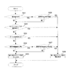
次に、振れ検出部201からの角速度信号と動きベクトル検出部212からの動きベクトルを用いて振れ補正ゲインを設定する際の振れ補正ゲイン設定部303の動作について、図4のフローチャートを用いて説明する。
Next, the operation of the shake correction
まず、ステップS101にて、振れ補正ゲイン制御部306からの指示が振れ補正ゲインの設定か否かを判定し、設定停止の指示である場合は振れ補正ゲインの設定を行わずに動作を終了する。
First, in step S101, it is determined whether or not the instruction from the shake correction
一方、振れ補正ゲインの設定が指示された場合はステップS101からステップS102へ進み、振れ検出部201から角速度信号と、動きベクトル検出部212から動きベクトルを、それぞれ取得する。そして、次のステップS103にて、ゲイン調整値係数を
ゲイン調整値係数=動きベクトル/角速度信号 ……………(1)
の(1)式により算出する。そして、次のステップS104にて、得られたゲイン調整値係数と所定値との比較を行う。この結果、算出したゲイン調整値係数が所定値より大きいとき、換言すれば、動きベクトルが大きいときは十分な像振れ補正効果が得られていないため、現在設定されている振れ補正ゲインは適切でないと判定してステップS106へ進む。そして、振れ補正ゲインが適切に設定されている時間を測定するための時間カウントをクリアする。そして、次のステップS108にて、ゲイン調整値係数に基づいて、ゲイン調整値係数が小さくなるように振れ補正ゲインの設定を行い、ステップS102へ戻り、同様の動作を繰り返す。
On the other hand, when setting of the shake correction gain is instructed, the process proceeds from step S101 to step S102, and the angular velocity signal is obtained from the
(1). Then, in the next step S104, the obtained gain adjustment value coefficient is compared with a predetermined value. As a result, when the calculated gain adjustment value coefficient is larger than the predetermined value, in other words, when the motion vector is large, a sufficient image blur correction effect is not obtained, and the currently set shake correction gain is not appropriate. And the process proceeds to step S106. And the time count for measuring the time when the shake correction gain is appropriately set is cleared. In the next step S108, based on the gain adjustment value coefficient, the shake correction gain is set so that the gain adjustment value coefficient becomes small, and the process returns to step S102 to repeat the same operation.
その後、算出したゲイン調整値係数が所定値以下となる、換言すれば、動きベクトルが小さくなったときは、設定した振れ補正ゲインは適切であると判定してステップS104からステップS105へ進む。そして、ステップS105にて、振れ補正ゲインが適切に設定されている時間を測定するための時間カウントをインクリメントする。そして、次のステップS107にて、時間カウントと所定時間とを比較し、時間カウントが所定時間より短い場合には、振れ補正ゲインが適切に設定されている時間が短いと判定してステップS102へ戻る。上記時間カウントが所定時間より短い場合とは、動く被写体を撮影している場合やパンニング動作を行っている際である。この際に検出された動きベクトルに基づいてゲイン調整値係数を算出すると、適切な振れ補正ゲインが得られないため、ステップS102へ戻り、以下同様の動作を繰り返すようにしている。 Thereafter, when the calculated gain adjustment value coefficient is equal to or smaller than the predetermined value, in other words, when the motion vector is small, it is determined that the set shake correction gain is appropriate, and the process proceeds from step S104 to step S105. In step S105, the time count for measuring the time for which the shake correction gain is appropriately set is incremented. Then, in the next step S107, the time count is compared with the predetermined time. If the time count is shorter than the predetermined time, it is determined that the time for which the shake correction gain is appropriately set is short, and the process proceeds to step S102. Return. The case where the time count is shorter than the predetermined time is a case where a moving subject is being photographed or a panning operation is being performed. If a gain adjustment value coefficient is calculated based on the motion vector detected at this time, an appropriate shake correction gain cannot be obtained. Therefore, the process returns to step S102, and the same operation is repeated thereafter.
その後、時間カウントが所定時間より長いと判定すると、ステップS107からステップS109へ進む。そして、ステップS109では、振れ補正ゲインが適切に設定されている時間が継続しており、この時の振れ補正ゲインは適切な値と推定できるため、現在の温度を温度判定部308より取り込み、この温度を記憶する。そして、次のステップS110にて、振れ補正ゲインの設定を完了する。
Thereafter, when it is determined that the time count is longer than the predetermined time, the process proceeds from step S107 to step S109. In step S109, the time during which the shake correction gain is appropriately set continues. Since the shake correction gain at this time can be estimated to be an appropriate value, the current temperature is taken in from the
次に、振れ補正ゲイン制御部306での動作、詳しくは撮影状態の変化の有無に応じて振れ補正ゲインの設定を開始させるもしくは停止させる動作について、図5のフローチャートを用いて説明する。
Next, an operation in the shake correction
まず、ステップS201にて、図4のステップS109で記憶されている温度と現在の温度とを比較し、温度が変化しているか否かの判定を行う。これは、温度変化によって角速度センサの出力が変化するため、温度に応じた適切な振れ補正量を設定する必要があるためである。その結果、温度変化が生じていると判定した場合はステップS206へ進み、振れ補正ゲイン設定部303に振れ補正ゲインの設定開始指示を行い、振れ補正ゲインの設定を開始させる。
First, in step S201, the temperature stored in step S109 of FIG. 4 is compared with the current temperature to determine whether the temperature has changed. This is because the output of the angular velocity sensor changes due to a temperature change, and it is necessary to set an appropriate shake correction amount according to the temperature. As a result, if it is determined that a temperature change has occurred, the process proceeds to step S206, where a shake correction gain setting start instruction is given to the shake correction
一方、温度変化が生じていないと判定した場合はステップS201からステップS202へ進み、コンバージョンレンズ判定部311からの情報よりコンバージョンレンズの着脱の有無を判定する。これは、コンバージョンレンズの着脱によってレンズの敏感度が変化するため、コンバージョンレンズの着脱によって適切な振れ補正量が異なるためである。コンバージョンレンズの着脱が有ったと判定した場合はステップS206へ進み、振れ補正ゲイン設定部303に振れ補正ゲインの設定開始指示を出し、振れ補正ゲインの設定を開始させる。また、コンバージョンレンズの着脱が無いと判定した場合にはステップS202からステップS203へ進む。
On the other hand, if it is determined that no temperature change has occurred, the process proceeds from step S201 to step S202, and whether or not the conversion lens is attached or detached is determined from information from the conversion
ステップS203では、ズーム位置判定部310からの情報よりズーム位置の変化の有無を判定する。これは、ズーム位置によってレンズの敏感度が変化するため、ズーム位置に応じて適切な振れ補正量が異なるためである。ズーム位置の変化が有ると判定した場合はステップS206へ進み、振れ補正ゲイン設定部303に振れ補正ゲインの設定開始指示を出し、振れ補正ゲインの設定を開始させる。また、ズーム位置の変化が無いと判定した場合はステップS203からステップS204へ進む。
In step S203, the presence / absence of a change in the zoom position is determined based on information from the zoom
ステップS204では、被写体距離判定部309からの情報より被写体距離の変化の有無を判定する。これは、被写体距離によってレンズの敏感度が変化するため、被写体距離に応じて適切な振れ補正量が異なるためである。被写体距離の変化が有ると判定した場合はステップS206へ進み、振れ補正ゲイン設定部303に振れ補正ゲインの設定開始指示を出し、振れ補正ゲインの設定を開始させる。被写体距離の変化が無いと判定した場合はステップ204からステップ205へ進み、振れ補正ゲイン設定部303に振れ補正ゲインの設定停止指示を出し、振れ補正ゲインの設定を停止させる。
In step S <b> 204, whether or not there is a change in the subject distance is determined from information from the subject
次に、以上のように構成された撮像装置の像振れ補正動作等について、図6に示すフローチャートを用いて説明する。 Next, an image shake correction operation and the like of the imaging apparatus configured as described above will be described with reference to a flowchart shown in FIG.
ステップS301にて、撮像装置の電源がオンされると、ステップS302以降の像振れ補正演動作を開始する。ここで、像振れ補正動作は一定周期毎(例えば250μsec)に発生する割り込み処理によって行われる。そして、第1の方向例えばピッチ方向と第2の方向、例えばヨー方向の制御が行われる。 In step S301, when the power of the imaging apparatus is turned on, the image blur correction performance operation after step S302 is started. Here, the image blur correction operation is performed by an interrupt process that occurs at regular intervals (for example, 250 μsec). Then, control in the first direction, for example, the pitch direction and the second direction, for example, the yaw direction is performed.
上記制御が開始されると、ステップS302にて、振れ補正モードが設定されているか否かの判定を振れ補正スイッチの状態より判定し、振れ補正スイッチがオフの時はステップS308へ進む。そして、振れ補正ゲインの設定を行わず、シフトレンズ103を中央(撮影光軸に一致する位置)固定とする。そして、ステップS309へ進む。
When the control is started, in step S302, it is determined whether or not the shake correction mode is set based on the state of the shake correction switch. When the shake correction switch is off, the process proceeds to step S308. Then, the shake correction gain is not set, and the
また、振れ補正スイッチがオンの時はステップS302からステップS303へ進み、振れ補正ゲインの設定が必要か否かの判定を行う。ここで、振れ補正ゲインの設定が必要な場合、つまり撮影状態の変化があった場合はステップS304へ進み、振れ補正ゲインの設定を行う。振れ補正ゲインの設定が必要でないと判定した場合、つまり撮影状態の変化がない場合はステップ305へ進み、振れ補正ゲインの設定を停止する。その後はステップS306へ進み、設定済みの振れ補正ゲインを用いて振れ量の算出を行う。そして、次のステップS307にて、算出された振れ量にて得られる補正位置制御信号によりシフトレンズ103を手振れ等の振れをキャンセルする方向に移動させる像振れ補正動作を行う。
When the shake correction switch is on, the process proceeds from step S302 to step S303, and it is determined whether or not a shake correction gain needs to be set. If the shake correction gain needs to be set, that is, if there is a change in the shooting state, the process proceeds to step S304, and the shake correction gain is set. When it is determined that the shake correction gain setting is not necessary, that is, when there is no change in the shooting state, the process proceeds to step 305 and the shake correction gain setting is stopped. Thereafter, the process proceeds to step S306, and the shake amount is calculated using the set shake correction gain. Then, in the next step S307, an image blur correction operation is performed in which the
その後、ステップS309にて、シャッタレリーズボタンが最後まで押し込まれたときにオンするスイッチ2(SW2)の状態を判定し、該スイッチ2がオンしていなければ直ちにステップS312へ進む。一方、スイッチ2がオンしていればステップS310へ進み、撮像部109への露光を開始し、所定の露光時間が経過するとステップS311へ進み、露光を終了する。そして、次のステップS312にて、電源スイッチがオンか否かを判定し、オンしていればステップS302へ戻り、以下同様の動作を終了する。電源スイッチがオフすると上記の動作を終了する。
Thereafter, in step S309, the state of the switch 2 (SW2) that is turned on when the shutter release button is fully depressed is determined. If the switch 2 is not turned on, the process immediately proceeds to step S312. On the other hand, if the switch 2 is on, the process proceeds to step S310 to start exposure to the
次に、本発明の実施例2に係る撮像装置について説明する。なお、撮像装置の構成は、実施例1にて説明した図1〜図3と同様である。また、図4および図6の各動作も実施例1と同様であるので、その説明は省略する。 Next, an image pickup apparatus according to Embodiment 2 of the present invention will be described. The configuration of the imaging apparatus is the same as that shown in FIGS. 1 to 3 described in the first embodiment. 4 and 6 are the same as those in the first embodiment, and the description thereof is omitted.
図7は、本発明の実施例2に係る振れ補正ゲイン制御部306での動作、詳しくは撮影状態の変化の有無に応じて振れ補正ゲインの設定を開始もしくは停止させる動作を示すフローチャートである。以下このフローチャートにしたがって説明する。
FIG. 7 is a flowchart showing an operation in the shake correction
まず、ステップS401にて、図4のステップS109で記憶されている温度と現在の温度を比較し、温度が変化しているか否かを判定する。その結果、温度変化が生じていない場合はステップS402へ進む。一方、温度変化が生じていると判定した場合はステップS406へ進み、その温度変化が所定温度以上かどうかの判定を行う。ここで、温度変化が所定温度以上の場合はステップS408へ進み、振れ補正ゲイン設定部303に振れ補正ゲインの設定開始指示を出し、振れ補正ゲインの設定を開始させる。また、温度変化が所定温度より小さい場合はステップS402へ進む。
First, in step S401, the temperature stored in step S109 in FIG. 4 is compared with the current temperature to determine whether the temperature has changed. As a result, if no temperature change has occurred, the process proceeds to step S402. On the other hand, if it is determined that a temperature change has occurred, the process proceeds to step S406, where it is determined whether the temperature change is equal to or higher than a predetermined temperature. If the temperature change is equal to or higher than the predetermined temperature, the process proceeds to step S408, and a shake correction gain setting start instruction is issued to the shake correction
ステップS402では、コンバージョンレンズの着脱の有無を判定し、コンバージョンレンズの着脱が有ると判定した場合はステップS408へ進み、振れ補正ゲイン設定部303に振れ補正ゲインの設定開始指示を出し、振れ補正ゲインの設定を開始させる。また、コンバージョンレンズの着脱が無いと判定した場合はステップS403へ進み、ズーム位置の変化の有無を判定する。その結果、ズーム位置の変化が有ると判定した場合はステップS408へ進み、振れ補正ゲイン設定部303に振れ補正ゲインの設定開始指示を出し、振れ補正ゲインの設定を開始させる。
In step S402, it is determined whether or not the conversion lens is attached / detached. If it is determined that the conversion lens is attached / detached, the process proceeds to step S408, and a shake correction gain setting start instruction is issued to the shake correction
上記ステップS403にてズーム位置の変化が無いと判定した場合はステップS404へ進み、被写体距離の変化の有無を判定する。その結果、被写体距離の変化が無いと判定した場合はステップS405へ進む。また、被写体距離の変化が有ると判定した場合はステップS407へ進み、被写体距離変化が所定値(所定距離)以上かどうかの判定を行う。ここで、被写体距離の変化が所定値以上と判定した場合はステップS408へ進み、振れ補正ゲイン設定部303に振れ補正ゲインの設定開始指示を出し、振れ補正ゲインの設定を開始させる。また、被写体距離の変化が所定値より小さいと判定した場合はステップS405へ進む。
If it is determined in step S403 that there is no change in the zoom position, the process proceeds to step S404, and it is determined whether or not the subject distance has changed. As a result, if it is determined that there is no change in the subject distance, the process proceeds to step S405. If it is determined that the subject distance has changed, the process proceeds to step S407, and it is determined whether the subject distance change is equal to or greater than a predetermined value (predetermined distance). If it is determined that the change in the subject distance is greater than or equal to the predetermined value, the process proceeds to step S408, where a shake correction gain setting start instruction is issued to the shake correction
ステップS405では、振れ補正ゲイン設定部303に振れ補正ゲインの設定停止指示を出し、振れ補正ゲインの設定を停止させる。
In step S405, a shake correction gain setting stop instruction is issued to the shake correction
次に、本発明の実施例3に係る撮像装置について説明する。なお、撮像装置の構成は、実施例1にて説明した図1〜図3と同様である。また、図5および図6の各動作も実施例1と同様であるので、その説明は省略する。 Next, an image pickup apparatus according to Embodiment 3 of the present invention will be described. The configuration of the imaging apparatus is the same as that shown in FIGS. 1 to 3 described in the first embodiment. The operations in FIGS. 5 and 6 are also the same as those in the first embodiment, and a description thereof will be omitted.
図8は、本発明の実施例3に係る、振れ検出部201からの角速度信号と動きベクトル検出部212からの動きベクトルをもとに振れ補正ゲインを設定する動作を示すフローチャートである。以下、このフローチャートにしたがって振れ補正ゲインを設定する動作について説明する。
FIG. 8 is a flowchart showing an operation for setting a shake correction gain based on the angular velocity signal from the
まず、ステップS501にて、振れ補正ゲイン設定の停止指示後、規定時間経過しているか否かの判定を行う。その結果、振れ補正ゲイン設定の停止指示があってから規定時間が経過していないと判定した場合は、振れ補正ゲイン設定を行わずに終了する。また、振れ補正ゲイン設定の停止指示後、規定時間経過していると判定した場合はステップS502へ進む。 First, in step S501, it is determined whether or not a specified time has elapsed after an instruction to stop the shake correction gain setting. As a result, if it is determined that the specified time has not elapsed since the instruction to stop the shake correction gain setting, the process is terminated without setting the shake correction gain. If it is determined that the specified time has elapsed after the stop instruction for setting the shake correction gain, the process proceeds to step S502.
次のステップ502では、振れ補正ゲイン制御部306からの指示が振れ補正ゲインの設定か否かの判定を行う。その結果、設定停止の指示である場合には、振れ補正ゲインの設定を行わずに終了する。一方、設定開始の指示である場合はステップS503へ進む。
In the next step 502, it is determined whether or not the instruction from the shake correction
ステップS503では、角速度センサと動きベクトルの取得を行う。そして、次のステップS504にて、ゲイン調整値係数を
ゲイン調整値係数=動きベクトル/角速度信号 ……………(2)
の(2)式により算出する。そして、次のステップS505にて、得られたゲイン調整値係数と所定値との比較を行う。算出したゲイン調整値係数が所定値以上のときは、振れ補正ゲインは適切でないと判定してステップ507へ進み、振れ補正ゲインが適切に設定されている時間を測定するための時間カウントをクリアする。そして、次のステップS509にて、ゲイン調整値係数に基づいて振れ補正ゲインの設定を行い、ステップS503へ戻る。
In step S503, an angular velocity sensor and a motion vector are acquired. In the next step S504, the gain adjustment value coefficient is changed to gain adjustment value coefficient = motion vector / angular velocity signal (2)
(2). In the next step S505, the gain adjustment value coefficient obtained is compared with a predetermined value. If the calculated gain adjustment value coefficient is equal to or greater than the predetermined value, it is determined that the shake correction gain is not appropriate, and the process proceeds to step 507 to clear the time count for measuring the time for which the shake correction gain is set appropriately. . In the next step S509, the shake correction gain is set based on the gain adjustment value coefficient, and the process returns to step S503.
また、上記ステップS505にて算出したゲイン調整値係数が所定値以下のときは、振れ補正ゲインは適切であると判定してステップS506へ進み、振れ補正ゲインが適切に設定されている時間を測定するための時間カウントをインクリメントする。そして、ステップS508へ進み、時間カウントと所定時間を比較し、所定時間より短い場合には、振れ補正ゲインが適切に設定されている時間が短いと判定してステップS503へ戻り、以下同様の動作を繰り返す。 If the gain adjustment value coefficient calculated in step S505 is less than or equal to a predetermined value, it is determined that the shake correction gain is appropriate, and the process proceeds to step S506 to measure the time for which the shake correction gain is set appropriately. Increment the time count to Then, the process proceeds to step S508, where the time count is compared with the predetermined time. If the time is shorter than the predetermined time, it is determined that the time for which the shake correction gain is properly set is short, the process returns to step S503, and so on. repeat.
また、上記ステップS508にて時間カウントが所定時間より長いと判定した場合はステップS510へ進む。そして、ステップS510では、振れ補正ゲインが適切に設定されている時間が継続しており、この時設定されている振れ補正ゲインは適切な値と推定できるので、その時の温度を記録する。その後はステップS511へ進み、振れ補正ゲイン設定を完了する。 If it is determined in step S508 that the time count is longer than the predetermined time, the process proceeds to step S510. In step S510, the time during which the shake correction gain is appropriately set continues, and the shake correction gain set at this time can be estimated to be an appropriate value, so the temperature at that time is recorded. Thereafter, the process proceeds to step S511, and the shake correction gain setting is completed.
上記実施例1ないし3における撮像装置は、以下の構成要素より成る。つまり、振れを検出する振れ検出部201,202、撮像部109にて取り込んだ画像信号から動きベクトルを検出する動きベクトル検出部212を有する。さらに、振れ出力に基づいて振れを補正するための振れ補正量を算出する防振制御部203,204を有する。さらに、振れ出力と動きべクトルを用いて振れ補正量の算出に用いられる前記振れ出力のゲインを調整するための振れ補正ゲインを設定する振れ補正ゲイン設定部303を有する。さらに、振れ補正量(補正位置制御信号)によりシフトレンズ103を駆動し、振れによる像振れを補正するシフトレンズ駆動制御部104を有する。さらに、振れ補正ゲインの設定を制御する振れ補正ゲイン制御部306を有する。
The imaging device according to the first to third embodiments includes the following components. That is, there are
詳しくは、振れ出力と動きべクトルとによりゲイン補正係数を算出し、該ゲイン補正係数をもとに前記振れ補正ゲインを設定するようにしている。そして、ゲイン補正係数が所定値以下になり、かつ、振れ補正ゲインの設定を開始してから所定時間が経過することにより、振れ補正ゲインの設定動作を停止するようにしている。 Specifically, a gain correction coefficient is calculated from a shake output and a motion vector, and the shake correction gain is set based on the gain correction coefficient. Then, the shake correction gain setting operation is stopped when the gain correction coefficient becomes equal to or less than a predetermined value and a predetermined time elapses after the setting of the shake correction gain is started.
また、撮像装置の使用前と使用時で温度変化が生じた、詳しくは撮像装置の使用前の温度と使用時の温度とに所定温度以上の差が生じた場合に、振れ補正ゲインの設定動作を開始させるようにしている。 In addition, when there is a temperature change before and during use of the imaging device, specifically when there is a difference of more than a specified temperature between the temperature before using the imaging device and the temperature during use, the shake correction gain setting operation To start.
また、焦点距離を変更するレンズ(コンバージョンレンズ)の取り付けまたは取り外しが行われた際に、前記振れ補正ゲインの設定動作を開始させるようにしている。あるいは/および、焦点距離変化(所定値以上の被写体距離変化)が生じた際に、振れ補正ゲインの設定動作を開始させるようにしている。あるいは/および、振れ補正ゲインの設定の停止後、所定時間が経過した後に、振れ補正ゲインの設定動作を開始させるようにしている。 In addition, when the lens (conversion lens) for changing the focal length is attached or detached, the setting operation of the shake correction gain is started. Alternatively, and / or when a focal length change (subject distance change greater than or equal to a predetermined value) occurs, a shake correction gain setting operation is started. Alternatively, the shake correction gain setting operation is started after a predetermined time has elapsed after the shake correction gain setting is stopped.
よって、常に適切な振れ補正ゲインを設定することができる。さらには、頻繁に振れ補正ゲインの設定を開始させないことで、演算処理の負荷が少なくなり、消費電力が抑えられるというメリットがある。 Therefore, it is possible to always set an appropriate shake correction gain. Furthermore, there is an advantage that the load of calculation processing is reduced and the power consumption can be suppressed by not frequently setting the shake correction gain.
(本発明と実施例の対応)
振れ検出部201,202が本発明の振れ検出手段に、撮像部109が本発明の撮像手段に、動きベクトル検出部212が、本発明の、撮像手段にて取り込んだ画像信号から動きベクトルを検出する動きベクトル検出手段に、それぞれ相当する。また、防振制御部203,204が、本発明の、振れ検出手段の振れ出力に基づいて振れを補正するための振れ補正量を算出する振れ補正量算出手段に相当する。また、振れ補正ゲイン設定部303が、本発明の、振れ出力と動きべクトルを用いて振れ補正量の算出に用いられる振れ補正ゲインを設定する振れ補正ゲイン設定手段に相当する。また、シフトレンズ駆動制御部104が、本発明の、振れ補正量により補正手段(シフトレンズ103)を駆動し、振れによる像振れを補正する制御手段に相当する。また、振れ補正ゲイン制御部306が、本発明の、撮影状態の変化に応じて振れ補正ゲインの設定を制御する振れ補正ゲイン制御手段に相当する。
(Correspondence between the present invention and the embodiment)
The
103 シフトレンズ
104 シフトレンズ駆動制御部
117 制御部
211 撮像部
201,202 振れ検出部
203,204 防振制御部
205,206 PID制御部
207,208 ドライブ部
209,210 位置検出部
212 動きベクトル検出部
303 振れ補正ゲイン設定部
306 振れ補正ゲイン制御部
308 温度判定部
309 被写体距離判定部
310 ズーム位置判定部
311 コンバージョンレンズ判定部
312 スイッチ
DESCRIPTION OF
Claims (9)
撮像手段にて取り込んだ画像信号から動きベクトルを検出する動きベクトル検出手段と、
前記振れ検出手段の振れ出力に基づいて前記振れを補正する振れ補正量を算出する振れ補正量算出手段と、
前記振れ検出手段の振れ出力と前記動きべクトルを用いて前記振れ補正量の算出に用いられる振れ補正ゲインを設定する振れ補正ゲイン設定手段と、
前記振れ補正量により補正手段を駆動し、前記振れによる像振れを補正する制御手段とを有する撮像装置において、
撮影状態の変化に応じて前記振れ補正ゲインの設定開始と停止を制御する振れ補正ゲイン制御手段を有することを特徴とする撮像装置。 Shake detection means for detecting shake;
Motion vector detection means for detecting a motion vector from an image signal captured by the imaging means;
A shake correction amount calculating means for calculating a shake correction amount for correcting the shake based on a shake output of the shake detection means;
A shake correction gain setting means for setting a shake correction gain used for calculation of the shake correction amount using the shake output of the shake detection means and the motion vector;
In an imaging apparatus having a control unit that drives a correction unit according to the shake correction amount and corrects image blur due to the shake,
An image pickup apparatus comprising shake correction gain control means for controlling start and stop of setting of the shake correction gain according to a change in photographing state.
Priority Applications (2)
| Application Number | Priority Date | Filing Date | Title |
|---|---|---|---|
| JP2008153401A JP2009300614A (en) | 2008-06-11 | 2008-06-11 | Imaging device |
| US12/466,262 US8508600B2 (en) | 2008-06-11 | 2009-05-14 | Imaging apparatus for stabilizing an image |
Applications Claiming Priority (1)
| Application Number | Priority Date | Filing Date | Title |
|---|---|---|---|
| JP2008153401A JP2009300614A (en) | 2008-06-11 | 2008-06-11 | Imaging device |
Publications (1)
| Publication Number | Publication Date |
|---|---|
| JP2009300614A true JP2009300614A (en) | 2009-12-24 |
Family
ID=41414382
Family Applications (1)
| Application Number | Title | Priority Date | Filing Date |
|---|---|---|---|
| JP2008153401A Pending JP2009300614A (en) | 2008-06-11 | 2008-06-11 | Imaging device |
Country Status (2)
| Country | Link |
|---|---|
| US (1) | US8508600B2 (en) |
| JP (1) | JP2009300614A (en) |
Cited By (7)
| Publication number | Priority date | Publication date | Assignee | Title |
|---|---|---|---|---|
| JP2011139169A (en) * | 2009-12-25 | 2011-07-14 | Canon Inc | Imaging apparatus |
| JP2011180302A (en) * | 2010-02-26 | 2011-09-15 | Nikon Corp | Shake correction device, lens barrel, and camera system |
| WO2018047406A1 (en) * | 2016-09-07 | 2018-03-15 | 富士フイルム株式会社 | Shake correction device, shake correction method, shake correction program, lens device, and imaging device |
| JP2018091855A (en) * | 2018-01-11 | 2018-06-14 | 株式会社ニコンビジョン | Distance detection device and distance detection method |
| JP2019029968A (en) * | 2017-08-03 | 2019-02-21 | キヤノン株式会社 | Imaging apparatus and control method thereof |
| US10539662B2 (en) | 2014-08-27 | 2020-01-21 | Nikon Vision Co., Ltd. | Range finder and optical device |
| JP2020046498A (en) * | 2018-09-18 | 2020-03-26 | 株式会社日立国際電気 | Imaging device and tremor-damping method |
Families Citing this family (6)
| Publication number | Priority date | Publication date | Assignee | Title |
|---|---|---|---|---|
| JP2012099876A (en) * | 2010-10-29 | 2012-05-24 | Sanyo Electric Co Ltd | Image processing device, imaging device, image processing method, and program |
| EP2533518B1 (en) * | 2011-06-10 | 2014-09-10 | Canon Kabushiki Kaisha | Shake compensation apparatus, shake compensation control method, and image capturing apparatus and control method thereof |
| JP2013055381A (en) * | 2011-08-31 | 2013-03-21 | Ricoh Co Ltd | Imaging apparatus, imaging method and portable information terminal device |
| CN104767930A (en) * | 2014-01-03 | 2015-07-08 | 三星电机株式会社 | Device used for image correction and method |
| US20150195457A1 (en) * | 2014-01-03 | 2015-07-09 | Samsung Electro-Mechanics Co., Ltd. | Apparatus and method for image correction |
| JP6584098B2 (en) * | 2015-03-09 | 2019-10-02 | キヤノン株式会社 | Imaging apparatus and control method thereof |
Citations (7)
| Publication number | Priority date | Publication date | Assignee | Title |
|---|---|---|---|---|
| JPH0682889A (en) * | 1992-09-04 | 1994-03-25 | Canon Inc | Camera |
| JPH10150595A (en) * | 1996-11-20 | 1998-06-02 | Sony Corp | Video camera |
| JP2004080457A (en) * | 2002-08-20 | 2004-03-11 | Ricoh Co Ltd | Image input apparatus |
| JP2004226692A (en) * | 2003-01-23 | 2004-08-12 | Nikon Corp | Vibration detecting device and blur correction camera |
| JP2005049591A (en) * | 2003-07-28 | 2005-02-24 | Nikon Corp | Photographic lens and camera system |
| JP2005203861A (en) * | 2004-01-13 | 2005-07-28 | Sony Corp | Imaging apparatus |
| JP2005303933A (en) * | 2004-04-15 | 2005-10-27 | Sony Corp | Imaging pickup device |
Family Cites Families (14)
| Publication number | Priority date | Publication date | Assignee | Title |
|---|---|---|---|---|
| JP3254733B2 (en) * | 1992-06-16 | 2002-02-12 | 松下電器産業株式会社 | Automatic gain control circuit |
| US6233009B1 (en) * | 1993-09-08 | 2001-05-15 | Canon Kabushiki Kaisha | Image-shake correcting device for detecting vibration frequency and for changing vibration characteristics |
| JP3661367B2 (en) * | 1997-09-09 | 2005-06-15 | コニカミノルタフォトイメージング株式会社 | Camera with shake correction function |
| JPH11196015A (en) * | 1997-12-26 | 1999-07-21 | Alps Electric Co Ltd | Receiving circuit |
| JP2001251152A (en) * | 2000-03-03 | 2001-09-14 | Matsushita Electric Ind Co Ltd | Device and method for automatically controlling gain and radio communication equipment provided with automatic gain control function |
| JP2005130045A (en) * | 2003-10-21 | 2005-05-19 | Konica Minolta Photo Imaging Inc | Image pickup apparatus and image pickup element used therefor |
| JP2005210261A (en) * | 2004-01-21 | 2005-08-04 | Renesas Technology Corp | Wireless communication system and high frequency ic |
| JP4717382B2 (en) * | 2004-06-15 | 2011-07-06 | キヤノン株式会社 | Optical equipment |
| JPWO2007097287A1 (en) | 2006-02-20 | 2009-07-16 | パナソニック株式会社 | Imaging device and lens barrel |
| JP4994756B2 (en) * | 2006-09-14 | 2012-08-08 | キヤノン株式会社 | Anti-vibration control device, optical apparatus including the same, imaging device, and control method of anti-vibration control device |
| JP4823179B2 (en) * | 2006-10-24 | 2011-11-24 | 三洋電機株式会社 | Imaging apparatus and imaging control method |
| JP4818189B2 (en) * | 2007-04-19 | 2011-11-16 | キヤノン株式会社 | Imaging apparatus and control method thereof |
| US7864477B1 (en) * | 2007-08-13 | 2011-01-04 | Marvell International Ltd. | Circuits, architectures, apparatuses, systems, algorithms and methods and software for automatic gain calibration of a burst signal stream |
| JP2009105784A (en) * | 2007-10-25 | 2009-05-14 | Sony Corp | Imaging apparatus |
-
2008
- 2008-06-11 JP JP2008153401A patent/JP2009300614A/en active Pending
-
2009
- 2009-05-14 US US12/466,262 patent/US8508600B2/en not_active Expired - Fee Related
Patent Citations (7)
| Publication number | Priority date | Publication date | Assignee | Title |
|---|---|---|---|---|
| JPH0682889A (en) * | 1992-09-04 | 1994-03-25 | Canon Inc | Camera |
| JPH10150595A (en) * | 1996-11-20 | 1998-06-02 | Sony Corp | Video camera |
| JP2004080457A (en) * | 2002-08-20 | 2004-03-11 | Ricoh Co Ltd | Image input apparatus |
| JP2004226692A (en) * | 2003-01-23 | 2004-08-12 | Nikon Corp | Vibration detecting device and blur correction camera |
| JP2005049591A (en) * | 2003-07-28 | 2005-02-24 | Nikon Corp | Photographic lens and camera system |
| JP2005203861A (en) * | 2004-01-13 | 2005-07-28 | Sony Corp | Imaging apparatus |
| JP2005303933A (en) * | 2004-04-15 | 2005-10-27 | Sony Corp | Imaging pickup device |
Cited By (15)
| Publication number | Priority date | Publication date | Assignee | Title |
|---|---|---|---|---|
| US8767079B2 (en) | 2009-12-25 | 2014-07-01 | Canon Kabushiki Kaisha | Image capture apparatus and control method thereof |
| JP2011139169A (en) * | 2009-12-25 | 2011-07-14 | Canon Inc | Imaging apparatus |
| JP2011180302A (en) * | 2010-02-26 | 2011-09-15 | Nikon Corp | Shake correction device, lens barrel, and camera system |
| US10539662B2 (en) | 2014-08-27 | 2020-01-21 | Nikon Vision Co., Ltd. | Range finder and optical device |
| WO2018047406A1 (en) * | 2016-09-07 | 2018-03-15 | 富士フイルム株式会社 | Shake correction device, shake correction method, shake correction program, lens device, and imaging device |
| JP6496883B2 (en) * | 2016-09-07 | 2019-04-10 | 富士フイルム株式会社 | Blur correction apparatus, blur correction method, blur correction program, lens apparatus, and imaging apparatus |
| JPWO2018047406A1 (en) * | 2016-09-07 | 2019-04-18 | 富士フイルム株式会社 | Shake correction apparatus, shake correction method, shake correction program, lens apparatus, and imaging apparatus |
| US10652467B2 (en) | 2016-09-07 | 2020-05-12 | Fujifilm Corporation | Shake correction device, shake correction method, shake correction program, lens device, and imaging device |
| US11089222B2 (en) | 2016-09-07 | 2021-08-10 | Fujifilm Corporation | Shake correction device, shake correction method, shake correction program, lens device, and imaging device |
| JP2019029968A (en) * | 2017-08-03 | 2019-02-21 | キヤノン株式会社 | Imaging apparatus and control method thereof |
| CN109391755A (en) * | 2017-08-03 | 2019-02-26 | 佳能株式会社 | Picture pick-up device and the method wherein executed |
| JP7009107B2 (en) | 2017-08-03 | 2022-01-25 | キヤノン株式会社 | Image pickup device and its control method |
| JP2018091855A (en) * | 2018-01-11 | 2018-06-14 | 株式会社ニコンビジョン | Distance detection device and distance detection method |
| JP2020046498A (en) * | 2018-09-18 | 2020-03-26 | 株式会社日立国際電気 | Imaging device and tremor-damping method |
| JP7202823B2 (en) | 2018-09-18 | 2023-01-12 | 株式会社日立国際電気 | Imaging device and damping method |
Also Published As
| Publication number | Publication date |
|---|---|
| US20090309985A1 (en) | 2009-12-17 |
| US8508600B2 (en) | 2013-08-13 |
Similar Documents
| Publication | Publication Date | Title |
|---|---|---|
| JP2009300614A (en) | Imaging device | |
| US8514290B2 (en) | Camera-shake correction apparatus and imaging apparatus including the same | |
| JP2018124582A (en) | Image stabilizer correction device and image stabilizer correction circuit, as well as image stabilizer correction method | |
| JP6472176B2 (en) | Imaging apparatus, image shake correction apparatus, image pickup apparatus control method, and image shake correction method | |
| JP5121674B2 (en) | Imaging device | |
| JP2011109329A (en) | Imaging device | |
| JP2013033160A (en) | Image blur correction device, its control method, and optical instrument or imaging apparatus | |
| JP2015203862A (en) | Image shake correction device and method for controlling the same, program, and storage medium | |
| JP2015185925A (en) | Imaging device and control method thereof | |
| JP5053819B2 (en) | Imaging apparatus and control method thereof | |
| JP6558891B2 (en) | Image shake correction apparatus and imaging apparatus | |
| JP6482197B2 (en) | Image shake correction apparatus, control method thereof, and imaging apparatus | |
| JP4983151B2 (en) | camera | |
| CN108737698B (en) | Image stabilization apparatus and method, image pickup apparatus, image pickup system, and storage medium | |
| JP2009069618A (en) | Imaging apparatus, control program, and record medium | |
| JP5164410B2 (en) | Imaging device | |
| JP6395401B2 (en) | Image shake correction apparatus, control method therefor, optical apparatus, and imaging apparatus | |
| JP4679236B2 (en) | Camera shake detection device and photographing device | |
| JP4487487B2 (en) | An imaging device equipped with a shake correction device | |
| JP6611585B2 (en) | Zoom control device, zoom control method, and imaging device | |
| JP4701006B2 (en) | Camera shake detection device and photographing device | |
| JP4909061B2 (en) | Imaging device | |
| JP2009300784A (en) | Camera shake correction device and camera shake correction method, and imaging device | |
| JP6700931B2 (en) | Image processing device, imaging device, and control method | |
| JP2015152886A (en) | Imaging device and control method of the same |
Legal Events
| Date | Code | Title | Description |
|---|---|---|---|
| RD01 | Notification of change of attorney |
Free format text: JAPANESE INTERMEDIATE CODE: A7421 Effective date: 20100520 |
|
| RD01 | Notification of change of attorney |
Free format text: JAPANESE INTERMEDIATE CODE: A7421 Effective date: 20100630 |
|
| A621 | Written request for application examination |
Free format text: JAPANESE INTERMEDIATE CODE: A621 Effective date: 20110606 |
|
| A977 | Report on retrieval |
Free format text: JAPANESE INTERMEDIATE CODE: A971007 Effective date: 20120621 |
|
| A131 | Notification of reasons for refusal |
Free format text: JAPANESE INTERMEDIATE CODE: A131 Effective date: 20120703 |
|
| A521 | Request for written amendment filed |
Free format text: JAPANESE INTERMEDIATE CODE: A523 Effective date: 20120829 |
|
| A02 | Decision of refusal |
Free format text: JAPANESE INTERMEDIATE CODE: A02 Effective date: 20130205 |