EP2432616B1 - Methode de separation d'une feuille en verre mince par faisceau laser - Google Patents
Methode de separation d'une feuille en verre mince par faisceau laser Download PDFInfo
- Publication number
- EP2432616B1 EP2432616B1 EP10778445.6A EP10778445A EP2432616B1 EP 2432616 B1 EP2432616 B1 EP 2432616B1 EP 10778445 A EP10778445 A EP 10778445A EP 2432616 B1 EP2432616 B1 EP 2432616B1
- Authority
- EP
- European Patent Office
- Prior art keywords
- glass
- glass sheet
- laser
- sheet
- laser beam
- Prior art date
- Legal status (The legal status is an assumption and is not a legal conclusion. Google has not performed a legal analysis and makes no representation as to the accuracy of the status listed.)
- Not-in-force
Links
- 239000011521 glass Substances 0.000 title claims description 138
- 238000000034 method Methods 0.000 title claims description 37
- 239000000463 material Substances 0.000 claims description 30
- 238000001816 cooling Methods 0.000 claims description 29
- 239000010409 thin film Substances 0.000 claims description 16
- 239000012530 fluid Substances 0.000 claims description 9
- 239000004065 semiconductor Substances 0.000 claims description 4
- 238000000151 deposition Methods 0.000 claims description 3
- 230000001902 propagating effect Effects 0.000 claims description 3
- 230000001678 irradiating effect Effects 0.000 claims 1
- 239000000758 substrate Substances 0.000 description 39
- 238000005520 cutting process Methods 0.000 description 33
- 239000010410 layer Substances 0.000 description 12
- 238000000926 separation method Methods 0.000 description 12
- 238000003698 laser cutting Methods 0.000 description 11
- 238000010438 heat treatment Methods 0.000 description 10
- 230000008569 process Effects 0.000 description 10
- 239000006060 molten glass Substances 0.000 description 7
- XLYOFNOQVPJJNP-UHFFFAOYSA-N water Substances O XLYOFNOQVPJJNP-UHFFFAOYSA-N 0.000 description 7
- 230000007547 defect Effects 0.000 description 6
- 230000008901 benefit Effects 0.000 description 5
- 230000003287 optical effect Effects 0.000 description 5
- VYPSYNLAJGMNEJ-UHFFFAOYSA-N Silicium dioxide Chemical compound O=[Si]=O VYPSYNLAJGMNEJ-UHFFFAOYSA-N 0.000 description 4
- 239000011324 bead Substances 0.000 description 4
- 239000006132 parent glass Substances 0.000 description 4
- 238000010791 quenching Methods 0.000 description 4
- 238000013459 approach Methods 0.000 description 3
- 238000005452 bending Methods 0.000 description 3
- 230000007423 decrease Effects 0.000 description 3
- 238000009826 distribution Methods 0.000 description 3
- 238000003280 down draw process Methods 0.000 description 3
- 239000001307 helium Substances 0.000 description 3
- 229910052734 helium Inorganic materials 0.000 description 3
- SWQJXJOGLNCZEY-UHFFFAOYSA-N helium atom Chemical compound [He] SWQJXJOGLNCZEY-UHFFFAOYSA-N 0.000 description 3
- 230000000644 propagated effect Effects 0.000 description 3
- 239000000919 ceramic Substances 0.000 description 2
- 239000000498 cooling water Substances 0.000 description 2
- 238000001704 evaporation Methods 0.000 description 2
- 230000008020 evaporation Effects 0.000 description 2
- 239000007789 gas Substances 0.000 description 2
- 230000005484 gravity Effects 0.000 description 2
- 238000004093 laser heating Methods 0.000 description 2
- 230000000171 quenching effect Effects 0.000 description 2
- 230000003252 repetitive effect Effects 0.000 description 2
- 239000005368 silicate glass Substances 0.000 description 2
- 239000000377 silicon dioxide Substances 0.000 description 2
- 239000005361 soda-lime glass Substances 0.000 description 2
- 238000004544 sputter deposition Methods 0.000 description 2
- 238000010521 absorption reaction Methods 0.000 description 1
- 230000004888 barrier function Effects 0.000 description 1
- 238000010549 co-Evaporation Methods 0.000 description 1
- 230000008602 contraction Effects 0.000 description 1
- 238000007796 conventional method Methods 0.000 description 1
- 239000002826 coolant Substances 0.000 description 1
- 239000012809 cooling fluid Substances 0.000 description 1
- 230000001419 dependent effect Effects 0.000 description 1
- 238000005137 deposition process Methods 0.000 description 1
- 238000011161 development Methods 0.000 description 1
- 239000003989 dielectric material Substances 0.000 description 1
- 230000009977 dual effect Effects 0.000 description 1
- 239000010408 film Substances 0.000 description 1
- 230000004927 fusion Effects 0.000 description 1
- 238000003286 fusion draw glass process Methods 0.000 description 1
- 239000002241 glass-ceramic Substances 0.000 description 1
- 230000006872 improvement Effects 0.000 description 1
- AMGQUBHHOARCQH-UHFFFAOYSA-N indium;oxotin Chemical compound [In].[Sn]=O AMGQUBHHOARCQH-UHFFFAOYSA-N 0.000 description 1
- 239000004973 liquid crystal related substance Substances 0.000 description 1
- 229910044991 metal oxide Inorganic materials 0.000 description 1
- 150000004706 metal oxides Chemical class 0.000 description 1
- 238000013021 overheating Methods 0.000 description 1
- 238000002161 passivation Methods 0.000 description 1
- 230000035515 penetration Effects 0.000 description 1
- 238000013001 point bending Methods 0.000 description 1
- 230000009467 reduction Effects 0.000 description 1
- 238000007652 sheet-forming process Methods 0.000 description 1
- 238000003283 slot draw process Methods 0.000 description 1
- 230000003068 static effect Effects 0.000 description 1
- 239000002344 surface layer Substances 0.000 description 1
- 238000012360 testing method Methods 0.000 description 1
- 230000008719 thickening Effects 0.000 description 1
- 230000007704 transition Effects 0.000 description 1
- 235000012431 wafers Nutrition 0.000 description 1
Images


Classifications
-
- B—PERFORMING OPERATIONS; TRANSPORTING
- B23—MACHINE TOOLS; METAL-WORKING NOT OTHERWISE PROVIDED FOR
- B23K—SOLDERING OR UNSOLDERING; WELDING; CLADDING OR PLATING BY SOLDERING OR WELDING; CUTTING BY APPLYING HEAT LOCALLY, e.g. FLAME CUTTING; WORKING BY LASER BEAM
- B23K26/00—Working by laser beam, e.g. welding, cutting or boring
- B23K26/36—Removing material
- B23K26/38—Removing material by boring or cutting
-
- C—CHEMISTRY; METALLURGY
- C03—GLASS; MINERAL OR SLAG WOOL
- C03B—MANUFACTURE, SHAPING, OR SUPPLEMENTARY PROCESSES
- C03B33/00—Severing cooled glass
- C03B33/09—Severing cooled glass by thermal shock
- C03B33/091—Severing cooled glass by thermal shock using at least one focussed radiation beam, e.g. laser beam
-
- B—PERFORMING OPERATIONS; TRANSPORTING
- B23—MACHINE TOOLS; METAL-WORKING NOT OTHERWISE PROVIDED FOR
- B23K—SOLDERING OR UNSOLDERING; WELDING; CLADDING OR PLATING BY SOLDERING OR WELDING; CUTTING BY APPLYING HEAT LOCALLY, e.g. FLAME CUTTING; WORKING BY LASER BEAM
- B23K26/00—Working by laser beam, e.g. welding, cutting or boring
- B23K26/36—Removing material
- B23K26/40—Removing material taking account of the properties of the material involved
-
- C—CHEMISTRY; METALLURGY
- C03—GLASS; MINERAL OR SLAG WOOL
- C03B—MANUFACTURE, SHAPING, OR SUPPLEMENTARY PROCESSES
- C03B33/00—Severing cooled glass
- C03B33/02—Cutting or splitting sheet glass or ribbons; Apparatus or machines therefor
- C03B33/0215—Cutting or splitting sheet glass or ribbons; Apparatus or machines therefor the ribbon being in a substantially vertical plane
-
- C—CHEMISTRY; METALLURGY
- C03—GLASS; MINERAL OR SLAG WOOL
- C03B—MANUFACTURE, SHAPING, OR SUPPLEMENTARY PROCESSES
- C03B33/00—Severing cooled glass
- C03B33/02—Cutting or splitting sheet glass or ribbons; Apparatus or machines therefor
- C03B33/023—Cutting or splitting sheet glass or ribbons; Apparatus or machines therefor the sheet or ribbon being in a horizontal position
- C03B33/0235—Ribbons
-
- C—CHEMISTRY; METALLURGY
- C03—GLASS; MINERAL OR SLAG WOOL
- C03B—MANUFACTURE, SHAPING, OR SUPPLEMENTARY PROCESSES
- C03B33/00—Severing cooled glass
- C03B33/02—Cutting or splitting sheet glass or ribbons; Apparatus or machines therefor
- C03B33/04—Cutting or splitting in curves, especially for making spectacle lenses
-
- C—CHEMISTRY; METALLURGY
- C03—GLASS; MINERAL OR SLAG WOOL
- C03B—MANUFACTURE, SHAPING, OR SUPPLEMENTARY PROCESSES
- C03B33/00—Severing cooled glass
- C03B33/09—Severing cooled glass by thermal shock
-
- B—PERFORMING OPERATIONS; TRANSPORTING
- B23—MACHINE TOOLS; METAL-WORKING NOT OTHERWISE PROVIDED FOR
- B23K—SOLDERING OR UNSOLDERING; WELDING; CLADDING OR PLATING BY SOLDERING OR WELDING; CUTTING BY APPLYING HEAT LOCALLY, e.g. FLAME CUTTING; WORKING BY LASER BEAM
- B23K2103/00—Materials to be soldered, welded or cut
- B23K2103/50—Inorganic material, e.g. metals, not provided for in B23K2103/02 – B23K2103/26
- B23K2103/52—Ceramics
-
- Y—GENERAL TAGGING OF NEW TECHNOLOGICAL DEVELOPMENTS; GENERAL TAGGING OF CROSS-SECTIONAL TECHNOLOGIES SPANNING OVER SEVERAL SECTIONS OF THE IPC; TECHNICAL SUBJECTS COVERED BY FORMER USPC CROSS-REFERENCE ART COLLECTIONS [XRACs] AND DIGESTS
- Y10—TECHNICAL SUBJECTS COVERED BY FORMER USPC
- Y10T—TECHNICAL SUBJECTS COVERED BY FORMER US CLASSIFICATION
- Y10T225/00—Severing by tearing or breaking
- Y10T225/30—Breaking or tearing apparatus
- Y10T225/304—Including means to apply thermal shock to work
Definitions
- This invention is directed to a method of separating a thin glass sheet comprising forming a full body crack in a glass sheet comprising a first surface, an opposing second surface and a thickness between the first and second surfaces, the full body crack intersecting the first and second surfaces.
- Conventional laser-cut glass can have a high median strength, typically better than 400 MPa. For comparison, the median strength of mechanically cut edges is roughly 100 MPa or less. However, the Weibull modulus, or "shape factor", m, for laser cut samples is low. A typical shape factor for samples prepared by conventional laser scoring, followed by a score and bend method for separating the sheet, is approximately 3, with a minimum edge strength of about 100 MPa. The low shape factor means the distribution of edge strength is fairly broad. This performance is problematic in applications where minimum edge strength is important for reliability reasons.
- a method of separating a thin glass sheet is defined in claim 1.
- the laser beam preferably comprises a wavelength between about 9 ⁇ m and 11 ⁇ m, and may be, for example, a CO 2 laser at a nominal wavelength of 10.6 ⁇ m.
- a thermal conductivity of an ambient atmosphere in contact with the sheet of brittle material is greater than about 0.024 W/m/K.
- the ambient atmosphere may comprise a large concentration of a high thermal conductivity gas.
- a length of the beam footprint where the beam intersects with the first surface and parallel with the predetermined path is, according to the present invention, greater than a speed of the traverse of the beam over the first surface of the brittle material multiplied by ( ⁇ c p d 2 )/4 ⁇ where ⁇ is the density of the glass plate, c p is the specific heat of the glass plate, ⁇ is the thermal conductivity of the glass plate and d is the thickness of the glass plate.
- an external tension force can be applied perpendicular to the pre-determined path during the traversing of the laser beam.
- the brittle material such as a thin glass sheet
- the distance between the spools increased without increasing a length of the brittle material between the spools (or increasing the length of brittle material between the spools less than the increase in distance between the spools) to apply a tension force.
- two spools need not be used and is merely illustrative.
- traversing the laser beam comprises passing the beam footprint only a single pass along the predetermined path.
- traversing the laser beam over the surface of the surface of the brittle material comprises a plurality of repetitive passes over the predetermined path.
- the full body crack that separates the sheet of brittle material into sub-sheets is propagated along the predetermined path only after a plurality of passes has been performed.
- the use of a plurality of passes is effective in separating out a closed figure, such as a generally rectangular shape (e.g. a rectangle with rounded corners).
- At least one of the sub-sheets can be further processed by depositing a dielectric or a semiconductor material on at least one of the at least two sub-sheets.
- one of the sub-sheets can have one or more thin film transistors deposited thereon by known deposition techniques (e.g. evaporation, sputtering, etc.).
- full body cutting refers to forming a crack in a sheet of brittle material (e.g. a thin glass sheet) that extends through the thickness of the material and across a dimension of the material such that the material is cleaved into separate pieces.
- brittle material e.g. a thin glass sheet
- forced fluid cooling refers to cooling a brittle material by directing a confined flow of a fluid, such as air or water trough a nozzle, onto a substrate to cool the substrate.
- a fluid such as air or water trough a nozzle
- a jet of pressurized water or air may be directed at a prescribed region of a glass plate behind a laser beam to quench the heated glass.
- Forced fluid cooling is to be distinguished from ambient cooling, or general cooling of the substrate through contact with the ambient atmosphere.
- the methods disclosed herein may be applied to a variety of thin brittle materials, such as glass, glass ceramics, ceramics or other similar materials (e.g. semiconductor wafers), one prominent use is the cutting of glass substrates used in display applications.
- This category includes, but is not limited to, television displays, computer displays, cell phone displays, and so forth. Consequently, the following description will be presented in the context of thin sheets of glass, with the understanding that the methods described can be applied to other materials.
- a score is first formed in the glass sheet along a pre-determined cutting path to create an initial flaw in the glass that extends substantially across the sheet, but not through the thickness of the sheet.
- the score may be made using a mechanical instrument, such as a hard scribe or wheel.
- a bending moment is then applied to the glass to induce a tensile stress along the score to create a crack ("vent crack” or "vent”) that propagates through the thickness of the sheet.
- the score may be produced by a laser beam. Again, a bending moment is applied to separate the sheet.
- a laser beam is traversed over an initial flaw (such as a nick at an edge of the sheet) to induce a crack at the flaw and then over the surface of the glass sheet along the cutting path to propagate the crack through the body of the glass and across a dimension of the sheet.
- the traversing laser beam is closely followed by a thin jet of a cooling fluid, typically water, to quench the heated glass and increase the stress, thereby driving the crack through the body of the glass and separating the sheet into several individual panes.
- the edge strength of glass substrates cut using a laser may vary widely, with a corresponding variation in the Weibull modulus, m, sometimes referred to as the "shape factor".
- Fracture analysis shows a dominating presence of twist hackle in the cut edges of low strength glass substrate samples separated according to conventional methods. Twist hackle occurs when a torsional stress (twisting) is applied to a material during the time a crack is propagating through the material. During laser separation of glass, twist hackle can be produced on the surfaces of the cut edge when uneven laser heating of the glass occurs. Twist hackle can be eliminated by balancing the temperature through the thickness of the glass substrate, which can result in a significant increase in the median strength of the cut sheet as well as the minimum edge strength and shape factor.
- Silica-based glass substrates suitable for use in display applications strongly absorb light in a wavelength range from about 9 ⁇ m to about 11 ⁇ m, and the penetration depth of such light in the glass substrates is usually limited to no more than about several wavelengths (e.g. 20 - 30 microns or less). It should be noted, however, that different glasses may strongly absorb at different wavelengths, and so the wavelength range needed for strong absorption may vary outside this range.
- a CO 2 laser emits light at 10.6 um wavelength, well within the 9 - 11 ⁇ m range. Thus, a beam emitted by a CO 2 laser is strongly absorbed by silica-based glass, and can be regarded as a surface heater.
- a strongly absorbed laser beam such as a CO 2 laser
- the time, ⁇ depth needed for the temperature to equilibrate through the sheet thickness can be estimated using the following equation: ⁇ depth ⁇ ⁇ c p 4 ⁇ d 2 where p is the glass density, c p is the specific heat of the glass, ⁇ is the heat conductivity of the glass, and d is the glass thickness.
- ⁇ depth increases as the square of the glass thickness.
- ⁇ depth is about 0.2 seconds.
- ⁇ depth decreases to 0.02 seconds, an approximately ten-fold reduction in time.
- a typical glass thickness for liquid crystal display (LCD) TV substrates, cell phones display substrates, and other hand-held devices is less than about 1 mm, and typically about 0.7 mm.
- the industrial trend is toward thin glass substrates of 0.5 mm or less. As the thickness d of the glass substrates decreases, the time needed to balance (equilibrate) the temperature over the glass thickness is significantly reduced.
- the surface layer can easily be heated to the strain or softening point of the glass material if the power of the beam is too high, or the residence time of the beam on the surface is too long. Because separation of the glass is dependent on the generation of high stress in the glass, heating of glass substrates above the softening point can subsequently decrease cutting speed by relieving stress in the glass. To prevent overheating, the laser beam can be shaped in a way that balances thermal conduction through the thickness of the material.
- the beam may be shaped into an elongated form using a cylindrical lens (a combination of positive-negative or positive-positive cylindrical lenses with crossed optical axes), or scanning techniques using optical scanners or rotating mirrors that effectively irradiate extended lengths of the substrate without the need to modify the shape of an otherwise circular beam.
- a cylindrical lens a combination of positive-negative or positive-positive cylindrical lenses with crossed optical axes
- scanning techniques using optical scanners or rotating mirrors that effectively irradiate extended lengths of the substrate without the need to modify the shape of an otherwise circular beam.
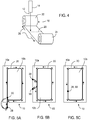
- Figure 1 is a schematic showing laser cutting of glass sheet 10 using an elongated laser beam 12 produced by laser 14 without forced fluid cooling.
- the glass sheet includes a first surface 9 and a second surface 13.
- the beam irradiates a "footprint" 16 on the first surface 9 of glass sheet 10 having a major axis oriented along the cutting direction 18, and a minor axis perpendicular to the major axis, wherein the boundaries of the footprint are defined wherein the intensity of the beam has been reduced to a value of 1/e 2 the peak intensity.
- the lengths of the major and minor axes of footprint 16 are denoted as b and a , respectively.
- the length b of the beam footprint on the glass sheet is greater than the traverse speed v of the beam (the speed of the "footprint", or area over which the beam impinges) multiplied by ⁇ depth .
- the laser cutting path is shown as dashed line 20, and the beam is shown moving to the left.
- FIGS. 2A - 2C illustrate the stress profile of a small strip of glass along the laser cutting path, the width of which is roughly twice the length a of the elongated (e.g. elliptical) beam minor axis.
- the stress profile through the glass thickness is shown at different times as the laser passes over the glass.
- FIG. 2A depicts the stress field present in the glass at the instant when the laser beam 12 begins to heat the irradiated surface and traverses over the surface.
- the figure shows that a compressive stress (indicated by the inward pointing arrows) develops close to the irradiated glass surface and a tensile stress develops farther below the surface (indicated by the outwardly pointing arrows - the length of the line connecting the arrows indicates relative magnitude of the stress).
- a compressive stress develops within the heated portion.
- the transverse time of the laser along the cutting line of the glass surface is determined by b/v, where, as before, v is the transverse speed of the laser beam relative to the glass substrate.
- heat from the irradiated surface is conducted through the thickness of the glass, and the stress profile is compressive at the outer surfaces of the glass (both the irradiated surface and the opposite surface) and tensile in the central portion of the glass sheet.
- FIG. 2C depicts the same region of glass shortly after the laser beam has moved away from the glass strip. Due to heat loss at the glass surfaces, the stress profile becomes tensile at the outer surfaces of the glass, and compressive within the central region of the glass. The stress profile of FIG. 2C , given enough temperature difference between the heated region and the rest of the glass substrate, is responsible for crack propagation and sheet separation.
- Sheet 10 may optionally comprise a thin film layer 11, such as a metal oxide layer (e.g. indium tin oxide - ITO), wherein the full body crack that separates the sheet of brittle material into sub-sheets, also separates the thin film layer.
- This film layer 11 may comprise multiple layers.
- the one or more thin film layers may, for example, comprise a thin film device such as a thin film transistor.
- the thin film layer may be a barrier layer or passivation layer.
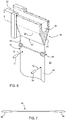
- Thin glass substrates rolled into a cylindrical drum may also be cut according to methods disclosed herein.
- glass is wound from a first drum or spool 22 to a second spool 24.
- a slight tension (arrows 26) is externally applied to the thin glass sheets perpendicular to cut line (pre-determined path) 20 during the separating process. That is, the tension is to be distinguished from tension that is formed by heating and/or cooling the glass.
- the tension may be applied by moving spools 22, 24 apart.
- the applied tension is to be distinguished from thermally developed stress (i.e. resulting from heating by the laser).
- Laser cutting can be carried out at the desired length by non-contact laser scoring to form an initial flaw, followed by CO 2 laser cutting without forced cooling to propagate a full body crack across the glass sheet.
- the applied tension serves a dual purpose. First, the applied tension facilitates an increase in laser cutting speed.
- the applied tension may also be used to maintain full body crack propagation in the desired cutting direction, since crack propagation is always perpendicular to the applied tensile stress.
- Yet another improvement in cutting speed can be achieved by pre-heating the glass substrate to higher temperatures along the cutting path. Pre-heating the glass substrate reduces the amount of heating required to be supplied by the cutting laser while propagating the full body crack.
- the glass sheet can be locally preheated along the predetermined cutting path by a flame or by a laser (either the cutting laser or another laser).
- FIGS. 5A - 5C show laser shape cutting of glass substrates using a galvanometer-based scanner.
- a defocused laser beam is rapidly scanned (indicated by the arrows) along a predetermined path 20 that traces the perimeter of a shaped part.
- an initial defect on the edge of glass substrate 10 is generated mechanically, or, in some embodiments, ablated with a focused laser beam, such as a focused CO 2 laser beam.
- the beam typically is initially positioned a short distance away from the glass substrate at a start position 28, then rapidly scanned over the edge defect, and along the pre-determined beam path 20. After rounding the fourth corner (the end position 30), the laser is turned off (extinguished) and the scanner is re-positioned to start position 28, the beam is turned back on and the cycle repeats along the same path. While the repetitive scans are taking place, and after a plurality of scans, a full-body crack is generated at the initial flaw substrate edge. The advancing crack front rapidly propagates along the laser beam path, until it encounters the already formed portion of the full body crack, and the crack front stops. A shaped cut is thus obtained, separating the parent sheet 10 into two sub-sheets 10a and 10b.
- FIG. 5B is another embodiment of a scanning method wherein the scan is started from a side of the rectangular part, rather than from a corner position as shown in FIG. 5A . With the preceding exception, the process proceeds as described with respect to FIG. 5A .
- FIG. 5C is still another embodiment comprising a closed-loop scan to heat the glass substrate.
- the start and stop positions are co-located on the scan path.
- the advantage of the closed loop scan method is that the scan is continuous: the laser will be kept on so long as the scan is in progress, and the initial mechanical defect is located in the path of the scanning beam. Because the defect is located off-edge, more tension is needed to generate the initial full body crack. The tension necessary to generate the initial full-body crack at the defect site can be induced by forced cooling at the defect site, wherein thereafter the scanning process and crack propagation around the pre-determined path is done without the need for forced cooling.
- a glass ribbon is formed by feeding molten glass to a forming body, and wherein the molten glass descends from the forming body.
- the descent of the molten glass may be due to gravity, or a combination of gravity and a separately applied pulling force.
- Down draw processes include well known slot draw processes, where the molten glass descends from a slot formed at the bottom of a hollow forming body, and fusion forming processes, where the molten glass flows over the sides of the forming body, fuses and descends from the bottom of the forming body.
- molten glass 32 is flowed into a conduit, or forming body 34, having a trough 36 at the top of the body.
- the trough is open so that the molten glass can overflow the walls of the trough and flow over the outer sides of the forming body in separate streams.
- the forming body includes outer forming surfaces 38, 40 over which the separate streams flow. The forming surfaces 38, 40 meet at the bottom or root 42 of the forming body, and rejoin (fuse) to form a continuous thin ribbon of glass 44.
- laser beams 12 emitted by lasers 14 are directed at a location on ribbon 44 inboard of the bulbous edge portions that has cooled to an elastic state such that the edge portions are separated from the remainder of the ribbon in accordance with foregoing embodiments.
- the temperature of the ribbon is significantly higher than the room temperature (several hundreds of degrees Celsius).
- the heat conduction of the ambient atmosphere can be improved by increasing the thermal conductivity of the ambient atmosphere 50.
- the percentage of helium in the atmosphere can be increased.
- Helium has a thermal conductivity of 0.142 W/m/K, which is significantly higher than the thermal conductivity of air, which is about 0.024 W/m/K.
- the ambient atmosphere is contact with the glass is made greater than about 0.024 W/m/K and preferably greater than about 0.1 W/m/K.
- the atmosphere can be increased to comprise up to 100% helium for example, or one or more other high thermal conductivity gases, alone or in combination, to remove heat from the surface of the ribbon and create the tension needed to cut the glass.
- a 12 watt (W) CO 2 laser was used to separate a 190 ⁇ m thick silicate glass substrate without forced cooling.
- a small flaw was first initiated at the edge of the glass using the cutting laser, modifying the beam with a 2" focal length plano-convex spherical lens. Once the initial flaw was created, a plano-convex and concave cylindrical lens was inserted into the beam path to form an elongated laser beam, and relative motion between the resulting elongated beam footprint and the substrate was increased to a terminal cutting speed of 45 mm/s. Residual stress remaining in the substrate after separation was negligible at the cutting speed.
- a CO 2 laser was used to separate a Corning EAGLE XGTM glass sheet of 0.63 mm thickness without forced cooling.
- An initial flaw was generated at an edge of the sheet with a CO 2 laser operating at 6.5 watts and a 2" focal length plano-convex spherical lens.
- plano-concave and convex cylindrical lenses were used to form an elongated beam using the same laser.
- the beam was elongated to a footprint length (major axis) of 9 mm and a footprint width (minor axis) of 0.6 mm.
- a terminal cutting speed of 9 mm/s was achieved and the substrate was successful cleaved in a single pass of the elongated beam footprint.
- plano-concave and convex cylindrical lenses were used to elongate the beam.
- the elongated beam was then traversed over the initial flaw and the surface of the parent glass sheet along a predetermined cutting path. This was repeated for non-forced cooling sample.
- the edge strength of each of the three samples sets was tested by subjecting each sample to a 4-point bending test. The results were plotted as a distribution (Weibull) of the probability of failure versus applied stress (MPa) and shown in FIG. 3 .
- FIG. 3 shows that samples cut with a cooling water jet (Batch 2 - indicated with triangles, center) and without a cooling water jet (Batch 1 - indicated with circles, far right) both outperformed the mechanical cut samples (Batch 3 - indicated by squares, far left) in terms of strength.
- the laser cut samples without using forced cooling exhibited an average strength of about 380 MPa while the laser cut samples with forced cooling exhibited an average strength of about 240 MPa.
- a CO 2 laser was used to separate soda-lime glass substrates of 1" x 0.5" and with a 0.7 mm thickness were laser cut without forced cooling.
- the soda lime glass had a coefficient of thermal expansion (CTE) of about 80x10 -7 /°C.
- An initial flaw was generated with the CO 2 laser running at 6.5 watts and a 2" focal length plano-convex and concave lens. After the initial flaw was formed, a plano-concave cylindrical lens was used to elongate the laser beam, and the beam was traversed over the initial flaw and the surface of the glass substrate along a predetermined cutting path to propagate a full body crack along the cutting path. A terminal cutting speed of 25 mm/s was achieved and the sample was successfully separated.
- a scanning method as shown in the embodiment of FIG. 5A is used in the shaped cutting process.
- a 75 um Corning code 0211 glass was used as the parent substrate.
- the parent glass substrate was approximately 120 by 150 mm.
- the laser beam was emitted from a CO 2 laser and was about 2 mm in cross sectional diameter.
- the laser power was about 80 watts, and the scanning speed was about 1500 mm/s.
- the shape being cut was about 100 x 120 mm in dimension, with a 5 mm corner radius. Crack propagation was observed less than 1 second after scanning with the laser beam was started. The scanning process was stopped once crack propagation was observed.
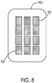
- sheet 10 becomes separated into sub-sheets 10a and 10b.
- one sub-piece can be a shape as described above and shown in FIG. 8 .
- One or more layers of materials 52 such as dielectrics or semiconductor materials, can thereafter be deposited on one of the sub-sheets (such as the generally rectangular sub-piece) according to conventional deposition processes (e.g. evaporation, co-evaporation, sputtering, etc.).
- the layers of material can comprise, for example, thin films such as ITO or a thin film transistor, and the sub-piece can be used in an electronic device, such as a display device.
- the thin film (or a thin film device) may be deposited on the glass sheet prior to the separation into two sub-sheets, and wherein the separation separates the thin film (or thin film device) comprising sub-sheet from the rest of the parent sheet.
Claims (6)
- Méthode de séparation d'une feuille de verre mince (10) comprenant la formation d'une fissure sur tout le corps (17) dans une feuille de verre (10) comprenant une première surface (9), une deuxième surface (13) opposée, et une épaisseur entre les première et deuxième surfaces (9,13), la fissure sur tout le corps (17) croisant les première et deuxième surfaces (9,13), caractérisée par :l'irradiation de la fissure sur tout le corps (17) avec un faisceau laser (12) ayant une longueur à la première surface (9) parallèle à un chemin prédéterminé (20) ; etle déplacement du faisceau laser (12) sur la première surface (9) le long d'un chemin prédéterminé (20) pour propager la fissure sur tout le corps (17) le long du chemin prédéterminé et séparer la feuille de verre (10) en au moins deux sous-feuilles de verre (10a, 10b), la fissure sur tout le corps (17) se propageant sans refroidissement par fluide en circulation forcée de la feuille de verre (10) ;caractérisée en outre en ce qu'une longueur du faisceau laser (12) à la première surface (9) parallèle à un chemin prédéterminé (20) est supérieure à une vitesse de déplacement multipliée par (ρcpd2)/4κ, ρ étant la densité de la feuille de verre (10), cp étant la chaleur spécifique de la feuille de verre (10), κ étant la conductivité thermique de la feuille de verre, et d étant l'épaisseur de la feuille de verre (10), l'épaisseur étant égale ou inférieure à 1 mm.
- Méthode selon la revendication 1, une conductivité thermique d'une atmosphère ambiante au contact de la feuille de verre (10) étant supérieure à environ 0,024 W/m/K.
- Méthode selon la revendication 1 ou 2, comprenant en outre l'application d'une force de tension externe perpendiculaire au chemin prédéterminé (20) au cours du déplacement.
- Méthode selon une quelconque des revendications 1 à 3, au moins une partie de la feuille de verre (10) étant disposée sur une bobine (22).
- Méthode selon une quelconque des revendications 1 à 4, la feuille de verre (10) comprenant un film mince (11) déposé dessus.
- Méthode selon une quelconque des revendications 1 à 4, comprenant en outre le dépôt d'un matériau diélectrique ou semi-conducteur sur au moins une des au moins deux sous-feuilles de verre (10a, 10b).
Applications Claiming Priority (2)
| Application Number | Priority Date | Filing Date | Title |
|---|---|---|---|
| US12/469,794 US8269138B2 (en) | 2009-05-21 | 2009-05-21 | Method for separating a sheet of brittle material |
| PCT/US2010/035715 WO2010135616A2 (fr) | 2009-05-21 | 2010-05-21 | Procédé de séparation d'une feuille de matériau cassant |
Publications (3)
| Publication Number | Publication Date |
|---|---|
| EP2432616A2 EP2432616A2 (fr) | 2012-03-28 |
| EP2432616A4 EP2432616A4 (fr) | 2015-02-11 |
| EP2432616B1 true EP2432616B1 (fr) | 2018-02-28 |
Family
ID=43123886
Family Applications (1)
| Application Number | Title | Priority Date | Filing Date |
|---|---|---|---|
| EP10778445.6A Not-in-force EP2432616B1 (fr) | 2009-05-21 | 2010-05-21 | Methode de separation d'une feuille en verre mince par faisceau laser |
Country Status (7)
| Country | Link |
|---|---|
| US (1) | US8269138B2 (fr) |
| EP (1) | EP2432616B1 (fr) |
| JP (1) | JP6018503B2 (fr) |
| KR (1) | KR101581992B1 (fr) |
| CN (1) | CN102458754B (fr) |
| TW (1) | TWI415811B (fr) |
| WO (1) | WO2010135616A2 (fr) |
Families Citing this family (77)
| Publication number | Priority date | Publication date | Assignee | Title |
|---|---|---|---|---|
| US8932510B2 (en) | 2009-08-28 | 2015-01-13 | Corning Incorporated | Methods for laser cutting glass substrates |
| US8946590B2 (en) | 2009-11-30 | 2015-02-03 | Corning Incorporated | Methods for laser scribing and separating glass substrates |
| JP5709032B2 (ja) * | 2010-02-12 | 2015-04-30 | 日本電気硝子株式会社 | ガラスフィルムの製造方法 |
| US8720228B2 (en) * | 2010-08-31 | 2014-05-13 | Corning Incorporated | Methods of separating strengthened glass substrates |
| US8607590B2 (en) * | 2010-11-30 | 2013-12-17 | Corning Incorporated | Methods for separating glass articles from strengthened glass substrate sheets |
| TWI548598B (zh) * | 2011-02-28 | 2016-09-11 | 康寧公司 | 熔融抽拉裝置及方法 |
| KR101800224B1 (ko) * | 2011-06-08 | 2017-11-22 | 니폰 덴키 가라스 가부시키가이샤 | 판형상 유리의 절단방법 및 그 절단장치 |
| US8635887B2 (en) * | 2011-08-10 | 2014-01-28 | Corning Incorporated | Methods for separating glass substrate sheets by laser-formed grooves |
| DE102011084128A1 (de) * | 2011-10-07 | 2013-04-11 | Schott Ag | Verfahren zum Schneiden eines Dünnglases mit spezieller Ausbildung der Kante |
| US8677783B2 (en) * | 2011-11-28 | 2014-03-25 | Corning Incorporated | Method for low energy separation of a glass ribbon |
| JP2013119510A (ja) * | 2011-12-08 | 2013-06-17 | Asahi Glass Co Ltd | レーザを用いてガラス基板を加工する方法 |
| KR101258403B1 (ko) * | 2011-12-09 | 2013-04-30 | 로체 시스템즈(주) | 강화유리 기판 절단방법 |
| CN103635438B (zh) * | 2011-12-12 | 2016-08-17 | 日本电气硝子株式会社 | 平板玻璃的切割分离方法 |
| US9938180B2 (en) | 2012-06-05 | 2018-04-10 | Corning Incorporated | Methods of cutting glass using a laser |
| KR20150037816A (ko) * | 2012-07-09 | 2015-04-08 | 아사히 가라스 가부시키가이샤 | 강화 유리판의 절단 방법 |
| DE112013003503B4 (de) * | 2012-07-10 | 2020-02-13 | AGC Inc. | Verfahren zur Bearbeitung einer Glasplatte |
| KR101355807B1 (ko) * | 2012-09-11 | 2014-02-03 | 로체 시스템즈(주) | 비금속 재료의 곡선 절단방법 |
| US9610653B2 (en) | 2012-09-21 | 2017-04-04 | Electro Scientific Industries, Inc. | Method and apparatus for separation of workpieces and articles produced thereby |
| US20140084039A1 (en) * | 2012-09-24 | 2014-03-27 | Electro Scientific Industries, Inc. | Method and apparatus for separating workpieces |
| US9216924B2 (en) | 2012-11-09 | 2015-12-22 | Corning Incorporated | Methods of processing a glass ribbon |
| DE102012110971A1 (de) * | 2012-11-14 | 2014-05-15 | Schott Ag | Trennen von transparenten Werkstücken |
| US9126857B2 (en) | 2012-11-15 | 2015-09-08 | Corning Incorporated | Separation apparatuses for separating sheets of brittle material and methods for separating sheets of brittle material |
| WO2014079478A1 (fr) | 2012-11-20 | 2014-05-30 | Light In Light Srl | Traitement par laser à grande vitesse de matériaux transparents |
| KR102002959B1 (ko) | 2012-11-20 | 2019-07-24 | 삼성디스플레이 주식회사 | 표시 장치의 제조 방법 |
| US9212081B2 (en) * | 2012-11-21 | 2015-12-15 | Corning Incorporated | Methods of cutting a laminate strengthened glass substrate |
| EP2754524B1 (fr) | 2013-01-15 | 2015-11-25 | Corning Laser Technologies GmbH | Procédé et dispositif destinés au traitement basé sur laser de substrats plats, galette ou élément en verre, utilisant un faisceau laser en ligne |
| KR102144324B1 (ko) * | 2013-02-04 | 2020-08-13 | 에이지씨 가부시키가이샤 | 유리 기판의 절단 방법, 유리 기판, 근적외선 커트 필터 유리, 유리 기판의 제조 방법 |
| KR20150123845A (ko) * | 2013-02-25 | 2015-11-04 | 코닝 인코포레이티드 | 얇은 유리 패널 제조 방법 |
| EP2781296B1 (fr) | 2013-03-21 | 2020-10-21 | Corning Laser Technologies GmbH | Dispositif et procédé de découpe de contours à partir de substrats plats au moyen d'un laser |
| JP2016117593A (ja) * | 2013-04-15 | 2016-06-30 | 旭硝子株式会社 | ガラス板の切断方法 |
| CN105939973B (zh) * | 2013-12-03 | 2019-08-20 | 康宁股份有限公司 | 用于切断玻璃板的设备和方法 |
| US9815730B2 (en) | 2013-12-17 | 2017-11-14 | Corning Incorporated | Processing 3D shaped transparent brittle substrate |
| US9850160B2 (en) | 2013-12-17 | 2017-12-26 | Corning Incorporated | Laser cutting of display glass compositions |
| US9701563B2 (en) | 2013-12-17 | 2017-07-11 | Corning Incorporated | Laser cut composite glass article and method of cutting |
| US10293436B2 (en) | 2013-12-17 | 2019-05-21 | Corning Incorporated | Method for rapid laser drilling of holes in glass and products made therefrom |
| US11556039B2 (en) | 2013-12-17 | 2023-01-17 | Corning Incorporated | Electrochromic coated glass articles and methods for laser processing the same |
| US9676167B2 (en) | 2013-12-17 | 2017-06-13 | Corning Incorporated | Laser processing of sapphire substrate and related applications |
| US10442719B2 (en) | 2013-12-17 | 2019-10-15 | Corning Incorporated | Edge chamfering methods |
| US20150165560A1 (en) | 2013-12-17 | 2015-06-18 | Corning Incorporated | Laser processing of slots and holes |
| US9260337B2 (en) * | 2014-01-09 | 2016-02-16 | Corning Incorporated | Methods and apparatus for free-shape cutting of flexible thin glass |
| KR101616952B1 (ko) * | 2014-01-14 | 2016-04-29 | 전상욱 | 취성 소재의 임의 형상 절단 방법 |
| JP6350884B2 (ja) * | 2014-02-03 | 2018-07-04 | 日本電気硝子株式会社 | レーザー溶断方法及び溶断面を有する板状ガラス製品 |
| EP3107868B1 (fr) | 2014-02-20 | 2021-05-26 | Corning Incorporated | Procédés permettant de pratiquer une découpe courbe sur du verre mince flexible |
| CN106029591B (zh) * | 2014-05-23 | 2019-08-23 | 日本电气硝子株式会社 | 面板的制造方法 |
| KR102445217B1 (ko) | 2014-07-08 | 2022-09-20 | 코닝 인코포레이티드 | 재료를 레이저 가공하는 방법 및 장치 |
| US10335902B2 (en) | 2014-07-14 | 2019-07-02 | Corning Incorporated | Method and system for arresting crack propagation |
| EP3169635B1 (fr) | 2014-07-14 | 2022-11-23 | Corning Incorporated | Procédé et système pour former des perforations |
| US10526234B2 (en) | 2014-07-14 | 2020-01-07 | Corning Incorporated | Interface block; system for and method of cutting a substrate being transparent within a range of wavelengths using such interface block |
| EP3552753A3 (fr) * | 2014-07-14 | 2019-12-11 | Corning Incorporated | Système et procédé de traitement de matériaux transparents utilisant des lignes focales de faisceau laser réglables en longueur et en diamètre |
| EP3183222B1 (fr) | 2014-08-20 | 2019-12-25 | Corning Incorporated | Méthode de découpe de verre fin et flexible permettant la réalisation de bord de haute résistance |
| TW201628751A (zh) * | 2014-11-20 | 2016-08-16 | 康寧公司 | 彈性玻璃基板之回饋控制的雷射切割 |
| US10047001B2 (en) | 2014-12-04 | 2018-08-14 | Corning Incorporated | Glass cutting systems and methods using non-diffracting laser beams |
| EP3708548A1 (fr) | 2015-01-12 | 2020-09-16 | Corning Incorporated | Découpage au laser de substrats trempés thermiquement à l'aide du procédé d'absorption multiphotonique |
| CN107922237B (zh) | 2015-03-24 | 2022-04-01 | 康宁股份有限公司 | 显示器玻璃组合物的激光切割和加工 |
| CN107666983B (zh) | 2015-03-27 | 2020-10-02 | 康宁股份有限公司 | 可透气窗及其制造方法 |
| JP7082042B2 (ja) | 2015-07-10 | 2022-06-07 | コーニング インコーポレイテッド | 可撓性基体シートに孔を連続形成する方法およびそれに関する製品 |
| WO2017180116A1 (fr) * | 2016-04-13 | 2017-10-19 | Gkn Aerospace North America Inc. | Système et procédé de fabrication d'additifs |
| CN109311725B (zh) | 2016-05-06 | 2022-04-26 | 康宁股份有限公司 | 从透明基材激光切割及移除轮廓形状 |
| US10410883B2 (en) | 2016-06-01 | 2019-09-10 | Corning Incorporated | Articles and methods of forming vias in substrates |
| US10794679B2 (en) | 2016-06-29 | 2020-10-06 | Corning Incorporated | Method and system for measuring geometric parameters of through holes |
| WO2018022476A1 (fr) | 2016-07-29 | 2018-02-01 | Corning Incorporated | Appareils et procédés de traitement laser |
| KR102423775B1 (ko) | 2016-08-30 | 2022-07-22 | 코닝 인코포레이티드 | 투명 재료의 레이저 가공 |
| US11243192B2 (en) | 2016-09-27 | 2022-02-08 | Vaon, Llc | 3-D glass printable hand-held gas chromatograph for biomedical and environmental applications |
| US10821707B2 (en) * | 2018-05-17 | 2020-11-03 | Vaon, Llc | Multi-layer, flat glass structures |
| US11203183B2 (en) | 2016-09-27 | 2021-12-21 | Vaon, Llc | Single and multi-layer, flat glass-sensor structures |
| CN109803786B (zh) | 2016-09-30 | 2021-05-07 | 康宁股份有限公司 | 使用非轴对称束斑对透明工件进行激光加工的设备和方法 |
| EP3529214B1 (fr) | 2016-10-24 | 2020-12-23 | Corning Incorporated | Station de traitement de substrat pour usinage laser de substrats en verre de type à vitre |
| US10752534B2 (en) | 2016-11-01 | 2020-08-25 | Corning Incorporated | Apparatuses and methods for laser processing laminate workpiece stacks |
| US10688599B2 (en) | 2017-02-09 | 2020-06-23 | Corning Incorporated | Apparatus and methods for laser processing transparent workpieces using phase shifted focal lines |
| WO2018175193A2 (fr) * | 2017-03-22 | 2018-09-27 | Corning Incorporated | Procédés de séparation d'une bande de verre |
| US10580725B2 (en) | 2017-05-25 | 2020-03-03 | Corning Incorporated | Articles having vias with geometry attributes and methods for fabricating the same |
| US11078112B2 (en) | 2017-05-25 | 2021-08-03 | Corning Incorporated | Silica-containing substrates with vias having an axially variable sidewall taper and methods for forming the same |
| US10626040B2 (en) | 2017-06-15 | 2020-04-21 | Corning Incorporated | Articles capable of individual singulation |
| WO2019026586A1 (fr) * | 2017-08-01 | 2019-02-07 | 坂東機工株式会社 | Machine à fendre les plaques de verre |
| US11554984B2 (en) | 2018-02-22 | 2023-01-17 | Corning Incorporated | Alkali-free borosilicate glasses with low post-HF etch roughness |
| US11524366B2 (en) * | 2018-07-26 | 2022-12-13 | Coherent Munich GmbH & Co. KG | Separation and release of laser-processed brittle material |
| CN110091072B (zh) * | 2019-05-28 | 2020-10-13 | 中国人民解放军国防科技大学 | 一种聚合物材料的瞬态激光烧蚀模拟方法 |
Citations (1)
| Publication number | Priority date | Publication date | Assignee | Title |
|---|---|---|---|---|
| US20020115235A1 (en) * | 2001-02-21 | 2002-08-22 | Hiroshi Sawada | Substrate cutting method |
Family Cites Families (38)
| Publication number | Priority date | Publication date | Assignee | Title |
|---|---|---|---|---|
| US3629545A (en) | 1967-12-19 | 1971-12-21 | Western Electric Co | Laser substrate parting |
| US4580336A (en) * | 1984-01-26 | 1986-04-08 | General Electric Company | Apparatus for slitting amorphous metal and method of producing a magnetic core therefrom |
| JPS61229487A (ja) * | 1985-04-03 | 1986-10-13 | Sasaki Glass Kk | レ−ザビ−ムによるガラス切断方法 |
| US5132505A (en) * | 1990-03-21 | 1992-07-21 | U.S. Philips Corporation | Method of cleaving a brittle plate and device for carrying out the method |
| KR920010885A (ko) * | 1990-11-30 | 1992-06-27 | 카나이 쯔또무 | 박막반도체와 그 제조방법 및 제조장치 및 화상처리장치 |
| JPH04349133A (ja) * | 1991-05-28 | 1992-12-03 | Seiko Epson Corp | ガラス部品の切断加工方法 |
| JP3036906B2 (ja) * | 1991-07-30 | 2000-04-24 | ホーヤ株式会社 | ガラス加工方法及びその装置 |
| RU2024441C1 (ru) | 1992-04-02 | 1994-12-15 | Владимир Степанович Кондратенко | Способ резки неметаллических материалов |
| JP3077462B2 (ja) * | 1993-09-01 | 2000-08-14 | 日立電線株式会社 | ガラスの切断方法 |
| US5622540A (en) | 1994-09-19 | 1997-04-22 | Corning Incorporated | Method for breaking a glass sheet |
| US5776220A (en) | 1994-09-19 | 1998-07-07 | Corning Incorporated | Method and apparatus for breaking brittle materials |
| US5585020A (en) * | 1994-11-03 | 1996-12-17 | Becker; Michael F. | Process for the production of nanoparticles |
| KR970008386A (ko) * | 1995-07-07 | 1997-02-24 | 하라 세이지 | 기판의 할단(割斷)방법 및 그 할단장치 |
| KR100447786B1 (ko) * | 1995-08-31 | 2004-11-06 | 코닝 인코포레이티드 | 취성물질절단방법및그장치 |
| US6306510B1 (en) * | 1998-07-15 | 2001-10-23 | Agfa-Gevaert | Laminate comprising a glass layer having crack lines |
| JP2000281373A (ja) * | 1999-03-26 | 2000-10-10 | Mitsubishi Electric Corp | 脆性材料の分割方法 |
| JP2000323441A (ja) | 1999-05-10 | 2000-11-24 | Hitachi Cable Ltd | セラミックス基板上に形成した光導波回路チップの切断方法 |
| DE19963939B4 (de) | 1999-12-31 | 2004-11-04 | Schott Spezialglas Gmbh | Verfahren und Vorrichtung zum Durchtrennen von flachen Werkstücken aus sprödbrüchigem Material |
| JP4786783B2 (ja) * | 2000-08-18 | 2011-10-05 | 日本板硝子株式会社 | ガラス板の切断方法及び記録媒体用ガラス円盤 |
| JP4659300B2 (ja) * | 2000-09-13 | 2011-03-30 | 浜松ホトニクス株式会社 | レーザ加工方法及び半導体チップの製造方法 |
| US6657723B2 (en) * | 2000-12-13 | 2003-12-02 | International Business Machines Corporation | Multimode planar spectrographs for wavelength demultiplexing and methods of fabrication |
| EP1341730B1 (fr) | 2000-12-15 | 2005-08-10 | LZH Laserzentrum Hannover E.V. | Procede pour decouper des composants constitues de verre, de ceramique, de vitroceramique ou d'un materiau analogue par realisation d'une fente thermique dans le composant le long d'une zone de decoupage |
| JP2003002676A (ja) | 2001-06-19 | 2003-01-08 | Seiko Epson Corp | 基板の分割方法及び液晶装置の製造方法 |
| JP2003002675A (ja) * | 2001-06-21 | 2003-01-08 | Nakamura Tome Precision Ind Co Ltd | ガラス板の割断方法及び装置 |
| JP2003019587A (ja) * | 2001-07-04 | 2003-01-21 | Inst Of Physical & Chemical Res | レーザー加工方法およびレーザー加工装置 |
| JP4474108B2 (ja) * | 2002-09-02 | 2010-06-02 | 株式会社 日立ディスプレイズ | 表示装置とその製造方法および製造装置 |
| US7294224B2 (en) | 2003-12-01 | 2007-11-13 | Applied Materials, Inc. | Magnet assembly for plasma containment |
| DE102004014277A1 (de) | 2004-03-22 | 2005-10-20 | Fraunhofer Ges Forschung | Verfahren zum laserthermischen Trennen von Flachgläsern |
| JP3873098B2 (ja) * | 2004-03-31 | 2007-01-24 | 国立大学法人 北海道大学 | レーザ加工方法および装置 |
| DE102004020737A1 (de) | 2004-04-27 | 2005-11-24 | Lzh Laserzentrum Hannover E.V. | Vorrichtung zum Durchtrennen von Bauteilen aus sprödbrüchigen Materialien mit spannungsfreier Bauteillagerung |
| DE102004024475A1 (de) | 2004-05-14 | 2005-12-01 | Lzh Laserzentrum Hannover E.V. | Verfahren und Vorrichtung zum Trennen von Halbleitermaterialien |
| JP2006159747A (ja) * | 2004-12-09 | 2006-06-22 | Japan Steel Works Ltd:The | レーザ加工方法及びその装置 |
| KR101152141B1 (ko) * | 2005-06-08 | 2012-06-15 | 삼성전자주식회사 | 액정표시패널과 액정표시패널의 제조방법 |
| KR101081613B1 (ko) | 2005-09-13 | 2011-11-09 | 가부시키가이샤 레미 | 취성재료의 할단방법 및 장치 |
| DE102006018622B3 (de) | 2005-12-29 | 2007-08-09 | H2B Photonics Gmbh | Vorrichtung zum durchtrennenden Bearbeiten von Bauteilen aus sprödbrüchigem Material |
| JP2007319888A (ja) | 2006-05-31 | 2007-12-13 | Sharp Corp | 被加工脆性部材のレーザー溶断方法 |
| US8168514B2 (en) * | 2006-08-24 | 2012-05-01 | Corning Incorporated | Laser separation of thin laminated glass substrates for flexible display applications |
| US20090040640A1 (en) * | 2007-08-07 | 2009-02-12 | Jinnam Kim | Glass cutting method, glass for flat panel display thereof and flat panel display device using it |
-
2009
- 2009-05-21 US US12/469,794 patent/US8269138B2/en active Active
-
2010
- 2010-05-20 TW TW99116134A patent/TWI415811B/zh active
- 2010-05-21 EP EP10778445.6A patent/EP2432616B1/fr not_active Not-in-force
- 2010-05-21 JP JP2012512055A patent/JP6018503B2/ja not_active Expired - Fee Related
- 2010-05-21 KR KR1020117029957A patent/KR101581992B1/ko active IP Right Grant
- 2010-05-21 WO PCT/US2010/035715 patent/WO2010135616A2/fr active Application Filing
- 2010-05-21 CN CN201080027736.8A patent/CN102458754B/zh active Active
Patent Citations (1)
| Publication number | Priority date | Publication date | Assignee | Title |
|---|---|---|---|---|
| US20020115235A1 (en) * | 2001-02-21 | 2002-08-22 | Hiroshi Sawada | Substrate cutting method |
Also Published As
| Publication number | Publication date |
|---|---|
| KR20120018798A (ko) | 2012-03-05 |
| EP2432616A2 (fr) | 2012-03-28 |
| CN102458754A (zh) | 2012-05-16 |
| WO2010135616A2 (fr) | 2010-11-25 |
| CN102458754B (zh) | 2016-04-06 |
| TWI415811B (zh) | 2013-11-21 |
| TW201103875A (en) | 2011-02-01 |
| WO2010135616A3 (fr) | 2011-02-24 |
| JP2012527400A (ja) | 2012-11-08 |
| EP2432616A4 (fr) | 2015-02-11 |
| US8269138B2 (en) | 2012-09-18 |
| US20100294748A1 (en) | 2010-11-25 |
| KR101581992B1 (ko) | 2015-12-31 |
| JP6018503B2 (ja) | 2016-11-02 |
Similar Documents
| Publication | Publication Date | Title |
|---|---|---|
| EP2432616B1 (fr) | Methode de separation d'une feuille en verre mince par faisceau laser | |
| US8943855B2 (en) | Methods for laser cutting articles from ion exchanged glass substrates | |
| US8584490B2 (en) | Laser cutting method | |
| US8426767B2 (en) | Methods for laser scribing and breaking thin glass | |
| JP5702785B2 (ja) | ガラス基板のレーザ切断方法 | |
| US8720228B2 (en) | Methods of separating strengthened glass substrates | |
| JP5976906B2 (ja) | ガラス基板のレーザスクライブおよび分離方法 | |
| US20130221053A1 (en) | Method and apparatus for separation of strengthened glass and articles produced thereby | |
| WO2013031778A1 (fr) | Procédé et dispositif de découpe de plaques en verre armé | |
| WO2008103239A1 (fr) | Finition de bord thermique | |
| WO2010108061A2 (fr) | Entaillage de précision au laser | |
| JP4831003B2 (ja) | レーザ照射によるガラス基板表面の表面傷部の修復法 | |
| US20200024188A1 (en) | Compositional modification of glass articles through laser heating and methods for making the same | |
| TW201831414A (zh) | 藉由形成劃痕線來雷射處理透明工件的方法 |
Legal Events
| Date | Code | Title | Description |
|---|---|---|---|
| PUAI | Public reference made under article 153(3) epc to a published international application that has entered the european phase |
Free format text: ORIGINAL CODE: 0009012 |
|
| 17P | Request for examination filed |
Effective date: 20111201 |
|
| AK | Designated contracting states |
Kind code of ref document: A2 Designated state(s): AL AT BE BG CH CY CZ DE DK EE ES FI FR GB GR HR HU IE IS IT LI LT LU LV MC MK MT NL NO PL PT RO SE SI SK SM TR |
|
| DAX | Request for extension of the european patent (deleted) | ||
| A4 | Supplementary search report drawn up and despatched |
Effective date: 20150112 |
|
| RIC1 | Information provided on ipc code assigned before grant |
Ipc: C03B 33/02 20060101ALI20150105BHEP Ipc: C03B 33/04 20060101ALI20150105BHEP Ipc: C03B 33/023 20060101ALI20150105BHEP Ipc: B23K 26/04 20140101ALI20150105BHEP Ipc: B23K 26/38 20140101AFI20150105BHEP Ipc: B23K 26/08 20140101ALI20150105BHEP Ipc: B23K 26/40 20140101ALI20150105BHEP Ipc: C03B 33/09 20060101ALI20150105BHEP |
|
| 17Q | First examination report despatched |
Effective date: 20151211 |
|
| GRAP | Despatch of communication of intention to grant a patent |
Free format text: ORIGINAL CODE: EPIDOSNIGR1 |
|
| INTG | Intention to grant announced |
Effective date: 20170630 |
|
| GRAJ | Information related to disapproval of communication of intention to grant by the applicant or resumption of examination proceedings by the epo deleted |
Free format text: ORIGINAL CODE: EPIDOSDIGR1 |
|
| GRAP | Despatch of communication of intention to grant a patent |
Free format text: ORIGINAL CODE: EPIDOSNIGR1 |
|
| INTC | Intention to grant announced (deleted) | ||
| INTG | Intention to grant announced |
Effective date: 20171121 |
|
| GRAS | Grant fee paid |
Free format text: ORIGINAL CODE: EPIDOSNIGR3 |
|
| GRAA | (expected) grant |
Free format text: ORIGINAL CODE: 0009210 |
|
| AK | Designated contracting states |
Kind code of ref document: B1 Designated state(s): AL AT BE BG CH CY CZ DE DK EE ES FI FR GB GR HR HU IE IS IT LI LT LU LV MC MK MT NL NO PL PT RO SE SI SK SM TR |
|
| REG | Reference to a national code |
Ref country code: GB Ref legal event code: FG4D Ref country code: CH Ref legal event code: EP |
|
| REG | Reference to a national code |
Ref country code: AT Ref legal event code: REF Ref document number: 973592 Country of ref document: AT Kind code of ref document: T Effective date: 20180315 |
|
| REG | Reference to a national code |
Ref country code: FR Ref legal event code: PLFP Year of fee payment: 9 |
|
| REG | Reference to a national code |
Ref country code: IE Ref legal event code: FG4D |
|
| REG | Reference to a national code |
Ref country code: DE Ref legal event code: R096 Ref document number: 602010048852 Country of ref document: DE |
|
| REG | Reference to a national code |
Ref country code: NL Ref legal event code: MP Effective date: 20180228 |
|
| REG | Reference to a national code |
Ref country code: LT Ref legal event code: MG4D |
|
| REG | Reference to a national code |
Ref country code: AT Ref legal event code: MK05 Ref document number: 973592 Country of ref document: AT Kind code of ref document: T Effective date: 20180228 |
|
| PG25 | Lapsed in a contracting state [announced via postgrant information from national office to epo] |
Ref country code: CY Free format text: LAPSE BECAUSE OF FAILURE TO SUBMIT A TRANSLATION OF THE DESCRIPTION OR TO PAY THE FEE WITHIN THE PRESCRIBED TIME-LIMIT Effective date: 20180228 Ref country code: NO Free format text: LAPSE BECAUSE OF FAILURE TO SUBMIT A TRANSLATION OF THE DESCRIPTION OR TO PAY THE FEE WITHIN THE PRESCRIBED TIME-LIMIT Effective date: 20180528 Ref country code: FI Free format text: LAPSE BECAUSE OF FAILURE TO SUBMIT A TRANSLATION OF THE DESCRIPTION OR TO PAY THE FEE WITHIN THE PRESCRIBED TIME-LIMIT Effective date: 20180228 Ref country code: HR Free format text: LAPSE BECAUSE OF FAILURE TO SUBMIT A TRANSLATION OF THE DESCRIPTION OR TO PAY THE FEE WITHIN THE PRESCRIBED TIME-LIMIT Effective date: 20180228 Ref country code: NL Free format text: LAPSE BECAUSE OF FAILURE TO SUBMIT A TRANSLATION OF THE DESCRIPTION OR TO PAY THE FEE WITHIN THE PRESCRIBED TIME-LIMIT Effective date: 20180228 Ref country code: LT Free format text: LAPSE BECAUSE OF FAILURE TO SUBMIT A TRANSLATION OF THE DESCRIPTION OR TO PAY THE FEE WITHIN THE PRESCRIBED TIME-LIMIT Effective date: 20180228 Ref country code: ES Free format text: LAPSE BECAUSE OF FAILURE TO SUBMIT A TRANSLATION OF THE DESCRIPTION OR TO PAY THE FEE WITHIN THE PRESCRIBED TIME-LIMIT Effective date: 20180228 |
|
| PG25 | Lapsed in a contracting state [announced via postgrant information from national office to epo] |
Ref country code: GR Free format text: LAPSE BECAUSE OF FAILURE TO SUBMIT A TRANSLATION OF THE DESCRIPTION OR TO PAY THE FEE WITHIN THE PRESCRIBED TIME-LIMIT Effective date: 20180529 Ref country code: SE Free format text: LAPSE BECAUSE OF FAILURE TO SUBMIT A TRANSLATION OF THE DESCRIPTION OR TO PAY THE FEE WITHIN THE PRESCRIBED TIME-LIMIT Effective date: 20180228 Ref country code: LV Free format text: LAPSE BECAUSE OF FAILURE TO SUBMIT A TRANSLATION OF THE DESCRIPTION OR TO PAY THE FEE WITHIN THE PRESCRIBED TIME-LIMIT Effective date: 20180228 Ref country code: AT Free format text: LAPSE BECAUSE OF FAILURE TO SUBMIT A TRANSLATION OF THE DESCRIPTION OR TO PAY THE FEE WITHIN THE PRESCRIBED TIME-LIMIT Effective date: 20180228 Ref country code: BG Free format text: LAPSE BECAUSE OF FAILURE TO SUBMIT A TRANSLATION OF THE DESCRIPTION OR TO PAY THE FEE WITHIN THE PRESCRIBED TIME-LIMIT Effective date: 20180528 |
|
| PG25 | Lapsed in a contracting state [announced via postgrant information from national office to epo] |
Ref country code: EE Free format text: LAPSE BECAUSE OF FAILURE TO SUBMIT A TRANSLATION OF THE DESCRIPTION OR TO PAY THE FEE WITHIN THE PRESCRIBED TIME-LIMIT Effective date: 20180228 Ref country code: RO Free format text: LAPSE BECAUSE OF FAILURE TO SUBMIT A TRANSLATION OF THE DESCRIPTION OR TO PAY THE FEE WITHIN THE PRESCRIBED TIME-LIMIT Effective date: 20180228 Ref country code: IT Free format text: LAPSE BECAUSE OF FAILURE TO SUBMIT A TRANSLATION OF THE DESCRIPTION OR TO PAY THE FEE WITHIN THE PRESCRIBED TIME-LIMIT Effective date: 20180228 Ref country code: PL Free format text: LAPSE BECAUSE OF FAILURE TO SUBMIT A TRANSLATION OF THE DESCRIPTION OR TO PAY THE FEE WITHIN THE PRESCRIBED TIME-LIMIT Effective date: 20180228 Ref country code: AL Free format text: LAPSE BECAUSE OF FAILURE TO SUBMIT A TRANSLATION OF THE DESCRIPTION OR TO PAY THE FEE WITHIN THE PRESCRIBED TIME-LIMIT Effective date: 20180228 |
|
| REG | Reference to a national code |
Ref country code: DE Ref legal event code: R097 Ref document number: 602010048852 Country of ref document: DE |
|
| PG25 | Lapsed in a contracting state [announced via postgrant information from national office to epo] |
Ref country code: CZ Free format text: LAPSE BECAUSE OF FAILURE TO SUBMIT A TRANSLATION OF THE DESCRIPTION OR TO PAY THE FEE WITHIN THE PRESCRIBED TIME-LIMIT Effective date: 20180228 Ref country code: SK Free format text: LAPSE BECAUSE OF FAILURE TO SUBMIT A TRANSLATION OF THE DESCRIPTION OR TO PAY THE FEE WITHIN THE PRESCRIBED TIME-LIMIT Effective date: 20180228 Ref country code: DK Free format text: LAPSE BECAUSE OF FAILURE TO SUBMIT A TRANSLATION OF THE DESCRIPTION OR TO PAY THE FEE WITHIN THE PRESCRIBED TIME-LIMIT Effective date: 20180228 Ref country code: SM Free format text: LAPSE BECAUSE OF FAILURE TO SUBMIT A TRANSLATION OF THE DESCRIPTION OR TO PAY THE FEE WITHIN THE PRESCRIBED TIME-LIMIT Effective date: 20180228 |
|
| REG | Reference to a national code |
Ref country code: CH Ref legal event code: PL |
|
| PLBE | No opposition filed within time limit |
Free format text: ORIGINAL CODE: 0009261 |
|
| STAA | Information on the status of an ep patent application or granted ep patent |
Free format text: STATUS: NO OPPOSITION FILED WITHIN TIME LIMIT |
|
| GBPC | Gb: european patent ceased through non-payment of renewal fee |
Effective date: 20180528 |
|
| REG | Reference to a national code |
Ref country code: BE Ref legal event code: MM Effective date: 20180531 |
|
| PG25 | Lapsed in a contracting state [announced via postgrant information from national office to epo] |
Ref country code: MC Free format text: LAPSE BECAUSE OF FAILURE TO SUBMIT A TRANSLATION OF THE DESCRIPTION OR TO PAY THE FEE WITHIN THE PRESCRIBED TIME-LIMIT Effective date: 20180228 |
|
| 26N | No opposition filed |
Effective date: 20181129 |
|
| REG | Reference to a national code |
Ref country code: IE Ref legal event code: MM4A |
|
| PG25 | Lapsed in a contracting state [announced via postgrant information from national office to epo] |
Ref country code: SI Free format text: LAPSE BECAUSE OF FAILURE TO SUBMIT A TRANSLATION OF THE DESCRIPTION OR TO PAY THE FEE WITHIN THE PRESCRIBED TIME-LIMIT Effective date: 20180228 Ref country code: LI Free format text: LAPSE BECAUSE OF NON-PAYMENT OF DUE FEES Effective date: 20180531 Ref country code: CH Free format text: LAPSE BECAUSE OF NON-PAYMENT OF DUE FEES Effective date: 20180531 |
|
| PG25 | Lapsed in a contracting state [announced via postgrant information from national office to epo] |
Ref country code: LU Free format text: LAPSE BECAUSE OF NON-PAYMENT OF DUE FEES Effective date: 20180521 |
|
| PG25 | Lapsed in a contracting state [announced via postgrant information from national office to epo] |
Ref country code: IE Free format text: LAPSE BECAUSE OF NON-PAYMENT OF DUE FEES Effective date: 20180521 Ref country code: GB Free format text: LAPSE BECAUSE OF NON-PAYMENT OF DUE FEES Effective date: 20180528 |
|
| PG25 | Lapsed in a contracting state [announced via postgrant information from national office to epo] |
Ref country code: BE Free format text: LAPSE BECAUSE OF NON-PAYMENT OF DUE FEES Effective date: 20180531 |
|
| PGFP | Annual fee paid to national office [announced via postgrant information from national office to epo] |
Ref country code: FR Payment date: 20190417 Year of fee payment: 10 |
|
| PG25 | Lapsed in a contracting state [announced via postgrant information from national office to epo] |
Ref country code: MT Free format text: LAPSE BECAUSE OF NON-PAYMENT OF DUE FEES Effective date: 20180521 |
|
| PG25 | Lapsed in a contracting state [announced via postgrant information from national office to epo] |
Ref country code: TR Free format text: LAPSE BECAUSE OF FAILURE TO SUBMIT A TRANSLATION OF THE DESCRIPTION OR TO PAY THE FEE WITHIN THE PRESCRIBED TIME-LIMIT Effective date: 20180228 |
|
| PG25 | Lapsed in a contracting state [announced via postgrant information from national office to epo] |
Ref country code: HU Free format text: LAPSE BECAUSE OF FAILURE TO SUBMIT A TRANSLATION OF THE DESCRIPTION OR TO PAY THE FEE WITHIN THE PRESCRIBED TIME-LIMIT; INVALID AB INITIO Effective date: 20100521 Ref country code: PT Free format text: LAPSE BECAUSE OF FAILURE TO SUBMIT A TRANSLATION OF THE DESCRIPTION OR TO PAY THE FEE WITHIN THE PRESCRIBED TIME-LIMIT Effective date: 20180228 |
|
| PG25 | Lapsed in a contracting state [announced via postgrant information from national office to epo] |
Ref country code: MK Free format text: LAPSE BECAUSE OF NON-PAYMENT OF DUE FEES Effective date: 20180228 |
|
| PG25 | Lapsed in a contracting state [announced via postgrant information from national office to epo] |
Ref country code: IS Free format text: LAPSE BECAUSE OF FAILURE TO SUBMIT A TRANSLATION OF THE DESCRIPTION OR TO PAY THE FEE WITHIN THE PRESCRIBED TIME-LIMIT Effective date: 20180628 |
|
| PG25 | Lapsed in a contracting state [announced via postgrant information from national office to epo] |
Ref country code: FR Free format text: LAPSE BECAUSE OF NON-PAYMENT OF DUE FEES Effective date: 20200531 |
|
| PGFP | Annual fee paid to national office [announced via postgrant information from national office to epo] |
Ref country code: DE Payment date: 20220411 Year of fee payment: 13 |
|
| REG | Reference to a national code |
Ref country code: DE Ref legal event code: R119 Ref document number: 602010048852 Country of ref document: DE |