EP2426761A2 - Électrode positive pour batterie secondaire à électrolyte non aqueux, batterie l'utilisant et procédé de fabrication de ladite électrode positive - Google Patents
Électrode positive pour batterie secondaire à électrolyte non aqueux, batterie l'utilisant et procédé de fabrication de ladite électrode positive Download PDFInfo
- Publication number
- EP2426761A2 EP2426761A2 EP11179737A EP11179737A EP2426761A2 EP 2426761 A2 EP2426761 A2 EP 2426761A2 EP 11179737 A EP11179737 A EP 11179737A EP 11179737 A EP11179737 A EP 11179737A EP 2426761 A2 EP2426761 A2 EP 2426761A2
- Authority
- EP
- European Patent Office
- Prior art keywords
- positive electrode
- compound
- battery
- aqueous electrolyte
- secondary battery
- Prior art date
- Legal status (The legal status is an assumption and is not a legal conclusion. Google has not performed a legal analysis and makes no representation as to the accuracy of the status listed.)
- Withdrawn
Links
Images


Classifications
-
- H—ELECTRICITY
- H01—ELECTRIC ELEMENTS
- H01M—PROCESSES OR MEANS, e.g. BATTERIES, FOR THE DIRECT CONVERSION OF CHEMICAL ENERGY INTO ELECTRICAL ENERGY
- H01M4/00—Electrodes
- H01M4/02—Electrodes composed of, or comprising, active material
- H01M4/36—Selection of substances as active materials, active masses, active liquids
- H01M4/362—Composites
- H01M4/364—Composites as mixtures
-
- H—ELECTRICITY
- H01—ELECTRIC ELEMENTS
- H01M—PROCESSES OR MEANS, e.g. BATTERIES, FOR THE DIRECT CONVERSION OF CHEMICAL ENERGY INTO ELECTRICAL ENERGY
- H01M4/00—Electrodes
- H01M4/02—Electrodes composed of, or comprising, active material
- H01M4/04—Processes of manufacture in general
- H01M4/0402—Methods of deposition of the material
- H01M4/0404—Methods of deposition of the material by coating on electrode collectors
-
- H—ELECTRICITY
- H01—ELECTRIC ELEMENTS
- H01M—PROCESSES OR MEANS, e.g. BATTERIES, FOR THE DIRECT CONVERSION OF CHEMICAL ENERGY INTO ELECTRICAL ENERGY
- H01M4/00—Electrodes
- H01M4/02—Electrodes composed of, or comprising, active material
- H01M4/13—Electrodes for accumulators with non-aqueous electrolyte, e.g. for lithium-accumulators; Processes of manufacture thereof
- H01M4/139—Processes of manufacture
- H01M4/1391—Processes of manufacture of electrodes based on mixed oxides or hydroxides, or on mixtures of oxides or hydroxides, e.g. LiCoOx
-
- H—ELECTRICITY
- H01—ELECTRIC ELEMENTS
- H01M—PROCESSES OR MEANS, e.g. BATTERIES, FOR THE DIRECT CONVERSION OF CHEMICAL ENERGY INTO ELECTRICAL ENERGY
- H01M4/00—Electrodes
- H01M4/02—Electrodes composed of, or comprising, active material
- H01M4/36—Selection of substances as active materials, active masses, active liquids
- H01M4/58—Selection of substances as active materials, active masses, active liquids of inorganic compounds other than oxides or hydroxides, e.g. sulfides, selenides, tellurides, halogenides or LiCoFy; of polyanionic structures, e.g. phosphates, silicates or borates
-
- H—ELECTRICITY
- H01—ELECTRIC ELEMENTS
- H01M—PROCESSES OR MEANS, e.g. BATTERIES, FOR THE DIRECT CONVERSION OF CHEMICAL ENERGY INTO ELECTRICAL ENERGY
- H01M4/00—Electrodes
- H01M4/02—Electrodes composed of, or comprising, active material
- H01M4/62—Selection of inactive substances as ingredients for active masses, e.g. binders, fillers
- H01M4/621—Binders
- H01M4/622—Binders being polymers
- H01M4/623—Binders being polymers fluorinated polymers
-
- H—ELECTRICITY
- H01—ELECTRIC ELEMENTS
- H01M—PROCESSES OR MEANS, e.g. BATTERIES, FOR THE DIRECT CONVERSION OF CHEMICAL ENERGY INTO ELECTRICAL ENERGY
- H01M4/00—Electrodes
- H01M4/02—Electrodes composed of, or comprising, active material
- H01M4/62—Selection of inactive substances as ingredients for active masses, e.g. binders, fillers
- H01M4/624—Electric conductive fillers
- H01M4/626—Metals
-
- Y—GENERAL TAGGING OF NEW TECHNOLOGICAL DEVELOPMENTS; GENERAL TAGGING OF CROSS-SECTIONAL TECHNOLOGIES SPANNING OVER SEVERAL SECTIONS OF THE IPC; TECHNICAL SUBJECTS COVERED BY FORMER USPC CROSS-REFERENCE ART COLLECTIONS [XRACs] AND DIGESTS
- Y02—TECHNOLOGIES OR APPLICATIONS FOR MITIGATION OR ADAPTATION AGAINST CLIMATE CHANGE
- Y02E—REDUCTION OF GREENHOUSE GAS [GHG] EMISSIONS, RELATED TO ENERGY GENERATION, TRANSMISSION OR DISTRIBUTION
- Y02E60/00—Enabling technologies; Technologies with a potential or indirect contribution to GHG emissions mitigation
- Y02E60/10—Energy storage using batteries
Definitions
- the present invention relates to a positive electrode for a non-aqueous electrolyte secondary battery, a battery using the positive electrode, and a method of manufacturing the positive electrode for a non-aqueous electrolyte secondary battery.
- the thickness of the positive electrode mixture slurry applied should be sufficiently large, in order to obtain high capacity and cost advantage by reducing the thickness of the components such as separator and current collector that are not directly involved in charge and discharge.
- the electrode plate becomes very stiff, lacking flexibility. This leads to such a problem that the positive electrode breaks during the winding of the electrode assembly and consequently the productivity of the battery considerably deteriorates.
- the present invention provides a positive electrode for a non-aqueous electrolyte secondary battery comprising: a positive electrode current collector; a positive electrode mixture layer formed on at least one surface of the positive electrode current collector, the positive electrode mixture layer containing a positive electrode active material, a water-based binder, and a conductive agent; the positive electrode active material comprising a lithium-transition metal composite oxide having at least one metallic compound selected from the group consisting of an aluminum compound, a zinc compound, a zirconium compound, a magnesium compound, and a rare earth compound, the at least one metallic compound adhered to a surface of the lithium-transition metal composite oxide; and the water-based binder comprising a latex rubber.
- the present invention provides the advantageous effects of improving productivity of a battery by increasing flexibility of the positive electrode, and improving the battery performance such as the storage performance in a charged state and the cycle performance (particularly the cycle performance at high-rate discharge).
- a positive electrode for a non-aqueous electrolyte secondary battery comprises: a positive electrode current collector; a positive electrode mixture layer formed on at least one surface of the positive electrode current collector, the positive electrode mixture layer containing a positive electrode active material, a water-based binder, and a conductive agent; the positive electrode active material comprising a lithium-transition metal composite oxide having at least one metallic compound selected from the group consisting of an aluminum compound, a zinc compound, a zirconium compound, a magnesium compound, and a rare earth compound, the at least one metallic compound adhered to a surface of the lithium-transition metal composite oxide; and the water-based binder comprising a latex rubber.
- the irregularity in the surface of the positive electrode active material is greater than when metallic compound is not adhered to the surface. Therefore, the dispersibility of the latex rubber is improved significantly, and the network of the latex rubber, which shows excellent binding capability, is uniformly formed in the positive electrode active material layer. Accordingly, the flexibility of the positive electrode is improved. As a result, productivity of the battery is dramatically improved because the positive electrode is prevented from breaking during winding the electrode assembly.
- the surface of the lithium-transition metal composite oxide can be inhibited from being exposed because the dispersibility of the latex rubber is improved (i.e., the latex rubber is dispersed uniformly over the surface of the lithium-transition metal composite oxide), so the decomposition reaction of the electrolyte solution at the positive electrode surface can be inhibited.
- the storage performance in a charged state under a high-temperature atmosphere and the cycle performance (particularly the cycle performance at high-rate discharge) is improved significantly.
- One reason for the significant improvement in the cycle performance is that the decomposition of the electrolyte solution is inhibited.
- the improvement in the flexibility of the positive electrode serves to maintain the binding performance between the positive electrode mixture layer and the positive electrode current collector even when the charge-discharge cycle is repeated (i.e., when the positive electrode active material undergoes expansion and shrinkage repeatedly).
- latex rubber means a rubber that can be dispersed in water, and it does not include water-soluble binder agents, such as CMC (carboxymethylcellulose).
- the latex rubber contain a fluorine-containing resin. It is also desirable that the fluorine-containing resin be PTFE.
- the flexibility of the positive electrode is improved further when the latex rubber contains a fluorine-containing resin such as PTFE.
- the at least one metallic compound be a rare earth compound. It is desirable that the rare earth compound be at least one compound selected from the group consisting of an yttrium compound, a lanthanum compound, a neodymium compound, a samarium compound, an erbium compound, and an ytterbium compound.
- the at least one metallic compound selected from the group consisting of an aluminum compound, a zinc compound, a zirconium compound, a magnesium compound, and a rare earth compound be at least one substance selected from the group consisting of a hydroxide, an oxyhydroxide, an acetate compound, a nitrate compound, and a sulfate compound.
- a hydroxide is particularly desirable.
- the acetate compound or the like changes into a hydroxide because the lithium transition metal oxide is alkaline. Therefore, the metallic compound exists in the form of a hydroxide in many cases, and that is why the hydroxide is desirable.
- the reason why the acetate compound, the nitrate compound, or the sulfate compound is desirable is that these compounds may remain on the surface of the lithium transition metal oxide without undergoing reactions.
- the reason why the acetate compound, the nitrate compound, or the sulfate compound is used for producing the metallic compound is that these compounds can be dissolved in water easily.
- an oxyhydroxide is desirable because, after preparing the positive electrode, the positive electrode may be subjected to a heat treatment (for example, a heat treatment at a temperature of from 230°C to 300°C), and in that case, a hydroxide changes into an oxyhydroxide.
- the metallic compound existing on the surface of the lithium-transition metal composite oxide have an average particle size of from 1 nm to 100 nm.
- the average particle size of the metallic compound is less than 1 nm, the irregularity in the surface of the positive electrode active material may be so small that the effect of improving the dispersibility of the latex rubber may not be fully exhibited.
- the average particle size of the metallic compound exceeds 100 nm, the amount of the metallic compound per unit area adhering to the surface will be so small that the effect of improving the dispersibility of the latex rubber may not be fully exhibited.
- the area of the lithium transition metal oxide exposed will be so large that the effect of inhibiting the decomposition reaction of the electrolyte solution cannot be fully exhibited either.
- the present invention also provides a non-aqueous electrolyte secondary battery comprising any one of the foregoing positive electrodes, a negative electrode, and a non-aqueous electrolyte.
- the present invention also provides a method of manufacturing a positive electrode for a non-aqueous electrolyte secondary battery, comprising the steps of: preparing a positive electrode active material by using a lithium-transition metal composite oxide and an aqueous solution having dissolved therein at least one metal salt selected from the group consisting of a rare earth salt, an aluminum salt, a zinc salt, a zirconium salt, and a magnesium salt, and adhering at least one metallic compound selected from the group consisting of a rare earth compound, an aluminum compound, a zinc compound, a zirconium compound, and a magnesium compound onto a surface of the lithium-transition metal composite oxide; preparing a positive electrode mixture slurry using the positive electrode active material, a conductive agent, and a latex rubber; and coating the positive electrode mixture slurry onto at least one surface of a positive electrode current collector, and thereafter drying the positive electrode mixture slurry, to prepare a positive electrode mixture layer.
- a positive electrode active material by using a lithium-transition metal
- the just-described method makes it possible to directly manufacture the positive electrode mixture slurry by using the lithium-transition metal composite oxide and the aqueous solution containing dissolved therein an aluminum salt, a zinc salt, a zirconium salt, a magnesium salt, and a rare earth salt, without drying the mixture.
- rare earth salt examples include nitrate, sulfate, chloride, and acetate.
- the following two techniques are examples of the technique of making a metallic compound adhere to the surface of the lithium-transition metal composite oxide by using a lithium-transition metal composite oxide and an aqueous solution having dissolved therein an aluminum salt, a zinc salt, a zirconium salt, a magnesium salt, or a rare earth salt.
- the conductive agent comprise a dispersion in which the conductive agent is dispersed by a thickening agent.
- the use of the dispersion in which the conductive agent is dispersed by a thickening agent serves to improve the dispersibility of the conductive agent.
- the resulting positive electrode active material was stirred while adding a dispersion having dispersed therein AB (acetylene black) as a conductive agent and CMC (carboxymethylcellulose) as a thickening agent thereto. Further, methyl methacrylate-butadiene rubber as a water-based binder (made of a latex rubber) was added thereto, to thus prepare a positive electrode mixture slurry.
- the positive electrode mixture slurry was prepared so that the mass ratio of the positive electrode active material, the AB, the CMC, and the methyl methacrylate-butadiene rubber was 94.5 : 2.5 : 0.5 : 1.0.
- the positive electrode mixture slurry was coated onto both sides of a positive electrode current collector made of an aluminum foil.
- the resultant article was then dried and rolled, whereby a positive electrode was prepared.
- the filling density of the positive electrode active material in this positive electrode was set at 3.60 g/cc.
- the amount of the adhering erbium compound was 0.067 mass % in terms of elemental erbium based on the mass of the lithium cobalt oxide.
- the resultant positive electrode active material was observed by SEM (see Fig. 6 ).
- the particle size of the erbium compound adhered to the particle surface of the lithium cobalt oxide was about 1 nm to about 100 nm, and that the particles of the erbium compound were adhered over the lithium cobalt oxide particle in a dispersed state.
- the flake-shaped particles with a size of about 200 nm or greater are lithium cobalt oxide particles.
- a carbon material (graphite), CMC, and SBR were mixed at a mass ratio of 97.5 : 1 : 1.5 in an aqueous solution to prepare a negative electrode mixture slurry. Thereafter, the negative electrode mixture slurry was coated onto both sides of a negative electrode current collector made of a copper foil, and the resultant article was then dried and rolled, whereby, a negative electrode was prepared.
- the filling density of the negative electrode active material was set at 1.75 g/cc.
- LiPF 6 as a lithium salt was dissolved at a concentration of 1 mol/L into a mixed solvent of 3 : 7 volume ratio of EC (ethylene carbonate) and DEC (diethyl carbonate), and 1 volume % of VC (vinylene carbonate) was added thereto, whereby a non-aqueous electrolyte solution was prepared.
- EC ethylene carbonate
- DEC diethyl carbonate
- VC vinyl carbonate
- the positive electrode and the negative electrode were disposed facing each other with the separators interposed therebetween.
- the positive electrode, the negative electrode, and the separators were spirally coiled using a winding core rod.
- the winding core rod was pulled out to prepare a spirally-wound electrode assembly, and then, the spirally-wound electrode assembly was compressed to prepare a flat-type electrode assembly.
- the just-described flat-type electrode assembly and the above-described electrolyte solution were put into an aluminum laminate battery case in a CO 2 atmosphere at 25°C and 1 atm, so that a flat-type non-aqueous electrolyte secondary battery was prepared.
- This battery had a design capacity of 750 mAh when charged to 4.4 V.
- This battery had dimensions of 3.6 mm in thickness, 35 mm in width, and 62 mm in length.
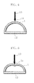
- the specific structure of the non-aqueous electrolyte secondary battery 11 is as follows. As illustrated in Figs. 1 and 2 , a positive electrode 1 and a negative electrode 2 are disposed so as to face each other across separators 3. A flat-type electrode assembly is constructed by the positive electrode 1, the negative electrode 2, and the separators 3, and a non-aqueous electrolyte solution is impregnated in the flat-type electrode assembly. The positive electrode 1 and the negative electrode 2 are connected to a positive electrode current collector tab 4 and a negative electrode current collector tab 5, respectively, so as to form a structure that enables charging and discharging as a secondary battery. The electrode assembly is disposed in a space within an aluminum laminate battery case 6 having a sealed part 7, at which opposing peripheral edges of the aluminum laminate films are heat sealed.
- a positive electrode and a battery were fabricated in the same manner as described in the just-described embodiment.
- Battery A1 of the invention The battery fabricated in this manner is hereinafter referred to as Battery A1 of the invention.
- a positive electrode and a battery were fabricated in the same manner as described in Example 1 above, except that in preparing the positive electrode, an aqueous solution in which 1.72 g of ytterbium acetate tetrahydrate was dissolved in 100 mL of pure water was used in place of the aqueous solution in which erbium acetate tetrahydrate was dissolved in pure water.
- the amount of the adhering ytterbium compound was 0.069 mass % in terms of elemental ytterbium based on the mass of the lithium cobalt oxide.
- the particle size of the ytterbium compound adhered to the surface of the lithium cobalt oxide particle was from about 1 nm to about 100 nm.
- the particles of the ytterbium compound were adhered over the lithium cobalt oxide particle in a dispersed state, as in Example 1.
- Battery A2 of the invention The battery fabricated in this manner is hereinafter referred to as Battery A2 of the invention.
- a positive electrode and a battery were fabricated in the same manner as described in Example 1 above, except that in preparing the positive electrode, an aqueous solution in which 1.39g of neodymium acetate monohydrate was dissolved in 100 mL of pure water was used in place of the aqueous solution in which erbium acetate tetrahydrate was dissolved in pure water.
- the amount of the adhering neodymium compound was 0.058 mass % in terms of elemental neodymium based on the mass of the lithium cobalt oxide.
- the particle size of the neodymium compound adhered to the surface of the lithium cobalt oxide particle was from about 1 nm to about 100 nm.
- the particles of the neodymium compound were adhered over the lithium cobalt oxide particle in a dispersed state, as in Example 1.
- Battery A3 of the invention The battery fabricated in this manner is hereinafter referred to as Battery A3 of the invention.
- a positive electrode and a battery were fabricated in the same manner as described in Example 1 above, except that in preparing the positive electrode, an aqueous solution in which 1.40 g of lanthanum acetate 1.5 hydrate was dissolved in 100 mL of pure water was used in place of the aqueous solution in which erbium acetate tetrahydrate was dissolved in pure water.
- the amount of the adhering lanthanum compound was 0.056 mass % in terms of elemental lanthanum based on the mass of the lithium cobalt oxide.
- the particle size of the lanthanum compound adhered to the surface of the lithium cobalt oxide particle was from about 1 nm to about 100 nm.
- the particles of the lanthanum compound were adhered over the lithium cobalt oxide particle in a dispersed state, as in Examples 1.
- Battery A4 of the invention The battery fabricated in this manner is hereinafter referred to as Battery A4 of the invention.
- a positive electrode and a battery were fabricated in the same manner as described in Example 1 above, except that in preparing the positive electrode, an aqueous solution in which 1.53 g of yttrium acetate pentahydrate was dissolved in 100 mL of pure water was used in place of the aqueous solution in which erbium acetate tetrahydrate was dissolved in pure water.
- the amount of the adhering yttrium compound was 0.036 mass % in terms of elemental yttrium based on the mass of the lithium cobalt oxide.
- the particle size of the yttrium compound adhered to the surface of the lithium cobalt oxide particle was from about 1 nm to about 100 nm.
- the particles of the yttrium compound were adhered over the lithium cobalt oxide particle in a dispersed state, as in Example 1.
- Battery A5 of the invention The battery fabricated in this manner is hereinafter referred to as Battery A5 of the invention.
- a positive electrode and a battery were fabricated in the same manner as described in Example 1 above, except that in preparing the positive electrode, an aqueous solution in which 1.63 g of samarium acetate tetrahydrate was dissolved in 100 mL of pure water was used in place of the aqueous solution in which erbium acetate tetrahydrate was dissolved in pure water.
- the amount of the adhering samarium compound was 0.060 mass % in terms of elemental samarium based on the mass of the lithium cobalt oxide.
- the particle size of the samarium compound adhered to the surface of the lithium cobalt oxide particle was from about 1 nm to about 100 nm.
- the particles of the samarium compound were adhered over the lithium cobalt oxide particle in a dispersed state, as in Example 1.
- Battery A6 The battery fabricated in this manner is hereinafter referred to as Battery A6 of the invention.
- a positive electrode and a battery were fabricated in the same manner as described in Example 1 above, except that in preparing the positive electrode, an aqueous solution in which 1.81 g of erbium nitrate pentahydrate was dissolved in 100 mL of pure water was used in place of the aqueous solution in which erbium acetate tetrahydrate was dissolved in pure water.
- the amount of the adhering erbium compound was 0.067 mass % in terms of elemental erbium based on the mass of the lithium cobalt oxide.
- the particle size of the erbium compound adhered to the surface of the lithium cobalt oxide particle was from about 1 nm to about 100 nm.
- the particles of the erbium compound were adhered over the lithium cobalt oxide particle in a dispersed state, as in Example 1.
- Battery A7 of the invention The battery fabricated in this manner is hereinafter referred to as Battery A7 of the invention.
- a positive electrode and a battery were fabricated in the same manner as described in Example 1 above, except that in preparing the positive electrode, the positive electrode mixture slurry was dried at 120°C for 3 yours after adding the aqueous solution in which 1.69 g of erbium acetate tetrahydrate was dissolved in 100 mL of pure water to LiCoO 2 and kneading the mixture.
- the amount of the adhering erbium compound was 0.067 mass % in terms of elemental erbium based on the mass of the lithium cobalt oxide.
- the particle size of the erbium compound adhered to the surface of the lithium cobalt oxide particle was from about 1 nm to about 100 nm.
- the particles of the erbium compound were adhered over the lithium cobalt oxide particle in a dispersed state, as in Example 1.
- Battery A8 of the invention The battery fabricated in this manner is hereinafter referred to as Battery A8 of the invention.
- a positive electrode and a battery were fabricated in the same manner as described in Example 1 above, except that in preparing the positive electrode, an aqueous solution in which 1.53 g of aluminum nitrate nonahydrate was dissolved in 100 mL of pure water was used in place of the aqueous solution in which erbium acetate tetrahydrate was dissolved in pure water.
- the amount of the adhering aluminum compound was 0.011 mass % in terms of elemental aluminum based on the mass of the lithium cobalt oxide.
- the particle size of the aluminum compound adhered to the surface of the lithium cobalt oxide particle was from about 1 nm to about 100 nm.
- the particles of the aluminum compound were adhered over the lithium cobalt oxide particle in a dispersed state, as in Example 1.
- Battery A9 of the invention The battery fabricated in this manner is hereinafter referred to as Battery A9 of the invention.
- a positive electrode and a battery were fabricated in the same manner as described in Example 1 above, except that in preparing the positive electrode, an aqueous solution in which 0.92 g of zirconium oxyacetate was dissolved in 100 mL of pure water was used in place of the aqueous solution in which erbium acetate tetrahydrate was dissolved in pure water.
- the amount of the adhering zirconium compound was 0.037 mass % in terms of elemental zirconium based on the mass of the lithium cobalt oxide.
- the particle size of the zirconium compound adhered to the surface of the lithium cobalt oxide particle was from about 1 nm to about 100 nm.
- the particles of the zirconium compound were adhered over the lithium cobalt oxide particle in a dispersed state, as in Example 1.
- Battery A10 The battery fabricated in this manner is hereinafter referred to as Battery A10 of the invention.
- a positive electrode and a battery were fabricated in the same manner as described in Example 1 above, except that in preparing the positive electrode, an aqueous solution in which 0.90 g of zinc acetate dihydrate was dissolved in 100 mL of pure water was used in place of the aqueous solution in which erbium acetate tetrahydrate was dissolved in pure water.
- the amount of the adhering zinc compound was 0.027 mass % in terms of elemental zinc based on the mass of the lithium cobalt oxide.
- the particle size of the zinc compound adhered to the surface of the lithium cobalt oxide particle was from about 1 nm to about 100 nm.
- the particles of the zinc compound were adhered over the lithium cobalt oxide particle in a dispersed state, as in Example 1.
- Battery A11 of the invention The battery fabricated in this manner is hereinafter referred to as Battery A11 of the invention.
- a positive electrode and a battery were fabricated in the same manner as described in Example 1 above, except that in preparing the positive electrode, an aqueous solution in which 1.05 g of magnesium nitrate hexahydrate was dissolved in 100 mL of pure water was used in place of the aqueous solution in which erbium acetate tetrahydrate was dissolved in pure water.
- the amount of the adhering magnesium compound was 0.01 mass % in terms of elemental magnesium based on the mass of the lithium cobalt oxide.
- the particle size of the magnesium compound adhered to the surface of the lithium cobalt oxide particle was from about 1 nm to about 100 nm.
- the particles of the magnesium compound were adhered over the lithium cobalt oxide particle in a dispersed state, as in Example 1.
- Battery A12 of the invention The battery fabricated in this manner is hereinafter referred to as Battery A12 of the invention.
- a positive electrode and a battery were fabricated in the same manner as described in Example 1 above, except that PTFE (polytetrafluoroethylene) was used as the latex rubber, in place of the methyl methacrylate-butadiene rubber, when preparing the positive electrode mixture slurry.
- PTFE polytetrafluoroethylene
- Battery A13 of the invention The battery fabricated in this manner is hereinafter referred to as Battery A13 of the invention.
- a positive electrode and a battery were prepared in the same manner as described in Example 1 above, except that LiNi 0.5 Co 0.2 Mn 0.3 O 2 was used as the positive electrode active material in place of LiCoO 2 (containing 1.0 mol % of Al and 1.0 mol % Mg in solid solution).
- the amount of the adhering erbium compound was 0.067 mass % in terms of elemental erbium based on the mass of the LiNi 0.5 Co 0.2 Mn 0.3 O 2 .
- the particle size of the erbium compound adhered to the surface of the lithium cobalt oxide particle was from about 1 nm to about 100 nm.
- the particles of the erbium compound were adhered over the LiNi 0.5 Co 0.2 Mn 0.3 O 2 particle in a dispersed state, as in Example 1.
- Battery A14 The battery fabricated in this manner is hereinafter referred to as Battery A14 of the invention.
- a positive electrode and a battery were prepared in the same manner as described in Example 1 above, except that a 1 : mass ratio mixture of LiCoO 2 (containing 1.0 mol% of Al and 1.0 mol% of Mg in solid solution) and LiNi 0.33 Co 0.33 Mn 0.33 O 2 was used as the positive electrode active material in place of LiCoO 2 (containing 1.0 mol % of Al and 1.0 mol % Mg in solid solution).
- the amount of the adhering erbium compound was 0.067 mass % in terms of elemental erbium based on the mass of the mixture of LiCoO 2 and LiNi 0.33 Co 0.33 Mn 0.33 O 2 .
- the particle size of the erbium compound adhered to each of the particle surfaces of the LiCoO 2 and the LiNi 0.33 Co 0.33 Mn 0.33 O 2 was from about 1 nm to about 100 nm.
- the particles of the erbium compound were adhered over the LiCoO 2 particle and the LiNi 0.33 Co 0.33 Mn 0.33 O 2 particle in a dispersed state, as in Example 1.
- Battery A15 The battery fabricated in this manner is hereinafter referred to as Battery A15 of the invention.
- a positive electrode and a battery were fabricated in the same manner as described in Example 1 above, except that in preparing the positive electrode, 100 mL of pure water alone was used in place of the aqueous solution in which erbium acetate tetrahydrate was dissolved in pure water.
- Comparative Battery Z1 The battery fabricated in this manner is hereinafter referred to as Comparative Battery Z1.
- a positive electrode and a battery were fabricated in the same manner as described in Comparative Examples 1 above, except that PTFE (polytetrafluoroethylene) was used as the latex rubber, in place of the methyl methacrylate-butadiene rubber, when preparing the positive electrode mixture slurry.
- PTFE polytetrafluoroethylene
- Comparative Battery Z2 The battery fabricated in this manner is hereinafter referred to as Comparative Battery Z2.
- a positive electrode and a battery were prepared in the same manner as described in Comparative Example 1 above, except that LiNi 0.5 Co 0.2 Mn 0.3 O 2 was used as the positive electrode active material in place of LiCoO2 (containing 1.0 mol % of Al and 1.0 mol % Mg in solid solution).
- Comparative Battery Z3 The battery fabricated in this manner is hereinafter referred to as Comparative Battery Z3.
- a positive electrode and a battery were prepared in the same manner as described in Comparative Example 1 above, except that a 1 : 1 mass ratio mixture of LiCoO 2 (containing 1.0 mol% of Al and 1.0 mol% of Mg in solid solution) and LiNi 0.33 Co 0.33 Mn 0.33 O 2 was used as the positive electrode active material in place of LiCoO 2 (containing 1.0 mol % of Al and 1.0 mol % Mg in solid solution).
- a positive electrode was cut out into a size of width 5 0mm ⁇ length 20 mm, and as illustrated in Fig. 4 , both ends of the cut-out positive electrode 1 were bonded to an end of an acrylic place 12 having a width of 30 mm using a double-sided tape.
- a central portion 1a of the positive electrode 1 was pressed with a pressing force 13.
- the speed of the pressing was a constant speed of 20 mm/min.
- Fig. 5 is a schematic cross-sectional view illustrating the positive electrode 1 in which a dent is formed by a pressing force 13 at its central portion 1a.
- the load obtained immediately before such a dent was formed was defined as the maximum value of the load.
- Fig. 3 is a graph illustrating the relationship between the load applied to the positive electrode and the displacement. As illustrated in Fig. 3 , the maximum value of the load was obtained as the maximum load. The maximum loads obtained for the respective positive electrodes are shown in Table 1, and each of the maximum load values indicates the flexibility of each of the positive electrodes. Table I shows that the smaller the value is, the greater the flexibility is.
- Residual capacity ratio % Discharge capacity obtained at the first - time discharge after the cotinuous charging test / Discharge capacity obtained before the continuous charging test ⁇ 100
- each of the batteries was charged at a constant current of 1.0 It (750 mA) to a battery voltage of 4.4 V and thereafter further charged at a constant voltage of 4.4 V to a current of It/20 (37.5 mA). Then, 10 minutes later the completion of the charging, each of the batteries was discharged at a constant current of 1.0 It (750 mA) until the battery voltage reached 2.75 V, and the discharge capacity before the continuous charging test was determined.
- each of the batteries was set aside in a thermostatic chamber at 60°C for 1 hour.
- each of the batteries was charged at a constant current of 1.0 It (750 mA) to a battery voltage of 4.4 V and thereafter further charged at a constant voltage of 4.4 V.
- the total charging time at 60°C was set at 72 hours, and after the time elapsed, each of the batteries was removed from the thermostatic chamber at 60°C. Then, after each of the batteries was cooled to room temperature, each of the batteries was discharged at a constant current of 1.0 It (750 mA) until the battery voltage reached 2.75 V, and the discharge capacity at the first-time discharge after the continuous charging test was obtained.
- a positive electrode was prepared in the same manner as described in Example 1 above, except that in preparing the positive electrode, PVdF [the solvent used was a NMP (N-methyl-2-pyrrolidone) solution] was used as the binder agent in place of the latex rubber, and that the mixture was prepared so that the mass ratio of LiCoO 2 , AB, and PVdF became 95 : 2.5 : 2.5, and the flexibility of the resulting positive electrode was determined in the foregoing manner. As a result, it was confirmed that the resulting positive electrode showed a flexibility of 146 Nm, almost as low as the positive electrode of Comparative Battery Z1.
- rare earth elements are not limited to erbium and the like as described above.
- Other rare earth elements such as scandium and cerium may also achieve the same advantageous effects.
- Capacity retention ratio % Discharge capacity at the 250 ⁇ th cycle / Discharge capacity at the first cycle ⁇ 100
- Each of the batteries was charged at a constant current of 1.0 It (750 mA) to a battery voltage of 4.4 V and thereafter further charged at a constant voltage of 4.4 V to a current of It/20 (37.5mA).
- Each of the batteries was discharged at a constant current of 2.671 It (2000 mA) until the battery voltage reached 2.75 V.
- the rest time between the charge test and the discharge test was 10 minutes.
- Batteries A1 and A8 through A12 of the invention are compared to each other, it is observed that Batteries A1 and A8 of the invention, each having a positive electrode containing an erbium compound adhered to the surface, exhibit higher capacity retention ratios after the 250th cycle than Batteries A9 through A12 of the invention, each having a positive electrode containing an aluminum compound or the like adhered to the surface.
- a rare earth compound such as an erbium compound be adhered to the lithium cobalt oxide surface.
- Batteries A1 and A8 through A12 of the invention are compared to each other, it is observed that Batteries A1 and A8 of the invention, each having a positive electrode containing an erbium compound adhered to the surface, exhibit better flexibility than Batteries A9 through A12 of the invention, each having a positive electrode containing an aluminum compound or the like adhered to the surface.
- a rare earth compound such as an erbium compound be adhered to the lithium cobalt oxide surface.
- Batteries A14 and A15 of the invention exhibit improvements in flexibility over Comparative Batteries Z3 and Z4.
- the effect of improvement in flexibility is more significant when using LiCoO 2 as the positive electrode active material than when using LiNi 0.5 Co 0.2 Mn 0.3 O 2 and when using a mixture of LiCoO 2 and LiNi 0.33 Co 0.33 Mn 0.33 O 2 (i.e., the effect of improving the flexibility obtained by Battery A1 of the invention over Comparative Battery Z1 is more significant than the effect of improving the flexibility obtained by Batteries A14 and A15 of the invention over Comparative Batteries Z3 and Z4). Although the reason is not fully understood, this is believed to be due to the differences in, for example, particle size, surface area, shape, and alkaline component of the positive electrode active materials.
- the present invention is expected to be applicable to the power sources for mobile information terminals such as mobile telephones, notebook computers, and PDAs, as well as the power sources for the applications that require high power, such as HEVs and power tools.
Landscapes
- Chemical & Material Sciences (AREA)
- Chemical Kinetics & Catalysis (AREA)
- Electrochemistry (AREA)
- General Chemical & Material Sciences (AREA)
- Engineering & Computer Science (AREA)
- Manufacturing & Machinery (AREA)
- Composite Materials (AREA)
- Inorganic Chemistry (AREA)
- Materials Engineering (AREA)
- Battery Electrode And Active Subsutance (AREA)
- Secondary Cells (AREA)
Applications Claiming Priority (3)
| Application Number | Priority Date | Filing Date | Title |
|---|---|---|---|
| JP2010195288 | 2010-09-01 | ||
| JP2011037922 | 2011-02-24 | ||
| JP2011120139A JP5758701B2 (ja) | 2010-09-01 | 2011-05-30 | 非水電解液二次電池用正極、それを用いた電池、及び非水電解液二次電池用正極の製造方法 |
Publications (2)
| Publication Number | Publication Date |
|---|---|
| EP2426761A2 true EP2426761A2 (fr) | 2012-03-07 |
| EP2426761A3 EP2426761A3 (fr) | 2013-12-25 |
Family
ID=44674401
Family Applications (1)
| Application Number | Title | Priority Date | Filing Date |
|---|---|---|---|
| EP11179737.9A Withdrawn EP2426761A3 (fr) | 2010-09-01 | 2011-09-01 | Électrode positive pour batterie secondaire à électrolyte non aqueux, batterie l'utilisant et procédé de fabrication de ladite électrode positive |
Country Status (3)
| Country | Link |
|---|---|
| EP (1) | EP2426761A3 (fr) |
| JP (1) | JP5758701B2 (fr) |
| CN (1) | CN102386376A (fr) |
Families Citing this family (13)
| Publication number | Priority date | Publication date | Assignee | Title |
|---|---|---|---|---|
| CN103855401A (zh) * | 2012-12-06 | 2014-06-11 | 上海比亚迪有限公司 | 一种锂离子电池正极极片及其制备方法和含有该极片的锂离子电池 |
| JP6158307B2 (ja) * | 2013-03-28 | 2017-07-05 | 三洋電機株式会社 | 非水電解質二次電池用正極、非水電解質二次電池用正極の製造方法および非水電解質二次電池 |
| JP6455124B2 (ja) * | 2013-12-24 | 2019-01-23 | 日亜化学工業株式会社 | 非水電解液二次電池用正極活物質及びその製造方法 |
| CN104752713B (zh) * | 2013-12-30 | 2019-01-25 | 北京当升材料科技股份有限公司 | 一种锂离子电池复合正极材料及其制备方法 |
| KR102311509B1 (ko) | 2014-12-12 | 2021-10-08 | 삼성에스디아이 주식회사 | 리튬 이차 전지용 양극 조성물, 그리고 이를 포함하는 리튬 이차 전지용 양극 및 리튬 이차 전지 |
| JP6632233B2 (ja) * | 2015-07-09 | 2020-01-22 | マクセルホールディングス株式会社 | 非水電解質二次電池 |
| CN107836056B (zh) * | 2015-08-06 | 2021-03-30 | 松下知识产权经营株式会社 | 非水电解质二次电池 |
| CN105449205A (zh) * | 2015-12-17 | 2016-03-30 | 山东精工电子科技有限公司 | 一种水系磷酸铁锂浆料制备方法 |
| CN106207128B (zh) * | 2016-08-31 | 2018-10-30 | 南开大学 | 一种Zr(OH)4包覆镍钴铝三元正极材料的制备方法 |
| WO2018179916A1 (fr) * | 2017-03-30 | 2018-10-04 | パナソニックIpマネジメント株式会社 | Matériau actif d'électrode positive destiné à une batterie secondaire à électrolyte non aqueux |
| JPWO2022034414A1 (fr) * | 2020-08-12 | 2022-02-17 | ||
| CN114023938B (zh) * | 2021-11-04 | 2023-06-09 | 山东零壹肆先进材料有限公司 | 一种正极材料及其制备方法和应用 |
| CN114361378B (zh) * | 2021-12-14 | 2024-03-29 | 宁德厦钨新能源材料有限公司 | 一种三元材料的电化学性能检测方法 |
Citations (3)
| Publication number | Priority date | Publication date | Assignee | Title |
|---|---|---|---|---|
| JP2006185887A (ja) | 2004-11-30 | 2006-07-13 | Matsushita Electric Ind Co Ltd | 非水電解液二次電池 |
| JP2008235157A (ja) | 2007-03-23 | 2008-10-02 | Matsushita Electric Ind Co Ltd | リチウム二次電池用正極活物質 |
| JP2009081072A (ja) | 2007-09-26 | 2009-04-16 | Furukawa Battery Co Ltd:The | 非水電解液二次電池用正極板の製造方法およびその正極板を用いた非水電解液二次電池 |
Family Cites Families (16)
| Publication number | Priority date | Publication date | Assignee | Title |
|---|---|---|---|---|
| JPH09245836A (ja) * | 1996-03-08 | 1997-09-19 | Fuji Photo Film Co Ltd | 非水電解質二次電池 |
| JP3692965B2 (ja) * | 2000-05-15 | 2005-09-07 | 株式会社デンソー | リチウム二次電池およびその正極の製造方法 |
| FR2822296A1 (fr) * | 2001-03-19 | 2002-09-20 | Atofina | Elements de batteries lithium-ion fabriques a partir d'une poudre microcomposite a base d'une charge et d'un fluoropolymere |
| JP4995382B2 (ja) * | 2001-07-05 | 2012-08-08 | 日本化学工業株式会社 | リチウムコバルト系複合酸化物、その製造方法、、リチウム二次電池正極活物質及びリチウム二次電池 |
| JP3944899B2 (ja) * | 2001-12-27 | 2007-07-18 | 株式会社ジーエス・ユアサコーポレーション | 非水系二次電池 |
| JP2004087227A (ja) * | 2002-08-26 | 2004-03-18 | Mitsui Mining Co Ltd | リチウム二次電池用負極 |
| US20040191633A1 (en) * | 2003-02-26 | 2004-09-30 | The University Of Chicago | Electrodes for lithium batteries |
| CN1274052C (zh) * | 2003-03-21 | 2006-09-06 | 比亚迪股份有限公司 | 锂离子二次电池的制造方法 |
| JP2005196992A (ja) * | 2003-12-26 | 2005-07-21 | Hitachi Ltd | リチウム二次電池用正極材料及び電池 |
| JP4683527B2 (ja) * | 2004-07-22 | 2011-05-18 | 日本化学工業株式会社 | 改質リチウムマンガンニッケル系複合酸化物、その製造方法、リチウム二次電池正極活物質及びリチウム二次電池 |
| JP4984478B2 (ja) * | 2005-10-04 | 2012-07-25 | 住友化学株式会社 | 正極活物質および非水電解質二次電池 |
| WO2007105818A1 (fr) * | 2006-03-15 | 2007-09-20 | Sumitomo Chemical Company, Limited | Poudre de materiau actif d'electrode positive |
| JP2008166118A (ja) * | 2006-12-28 | 2008-07-17 | Samsung Sdi Co Ltd | リチウム二次電池用の負極活物質及びリチウム二次電池 |
| JP2009048921A (ja) * | 2007-08-22 | 2009-03-05 | Sanyo Electric Co Ltd | 非水電解質電池用正極及びその製造方法と非水電解質電池及びその製造方法 |
| JP2009099523A (ja) * | 2007-09-27 | 2009-05-07 | Sanyo Electric Co Ltd | リチウム二次電池 |
| JP4989670B2 (ja) * | 2008-09-30 | 2012-08-01 | 三洋電機株式会社 | 非水電解質二次電池用正極活物質、非水電解質二次電池用正極活物質の製造方法、非水電解質二次電池用正極及び非水電解質二次電池 |
-
2011
- 2011-05-30 JP JP2011120139A patent/JP5758701B2/ja active Active
- 2011-08-31 CN CN2011102587492A patent/CN102386376A/zh active Pending
- 2011-09-01 EP EP11179737.9A patent/EP2426761A3/fr not_active Withdrawn
Patent Citations (3)
| Publication number | Priority date | Publication date | Assignee | Title |
|---|---|---|---|---|
| JP2006185887A (ja) | 2004-11-30 | 2006-07-13 | Matsushita Electric Ind Co Ltd | 非水電解液二次電池 |
| JP2008235157A (ja) | 2007-03-23 | 2008-10-02 | Matsushita Electric Ind Co Ltd | リチウム二次電池用正極活物質 |
| JP2009081072A (ja) | 2007-09-26 | 2009-04-16 | Furukawa Battery Co Ltd:The | 非水電解液二次電池用正極板の製造方法およびその正極板を用いた非水電解液二次電池 |
Also Published As
| Publication number | Publication date |
|---|---|
| EP2426761A3 (fr) | 2013-12-25 |
| JP5758701B2 (ja) | 2015-08-05 |
| CN102386376A (zh) | 2012-03-21 |
| JP2012190773A (ja) | 2012-10-04 |
Similar Documents
| Publication | Publication Date | Title |
|---|---|---|
| EP2426761A2 (fr) | Électrode positive pour batterie secondaire à électrolyte non aqueux, batterie l'utilisant et procédé de fabrication de ladite électrode positive | |
| US9299984B2 (en) | Lithium secondary battery having positive electrode active material including lithium transition metal composite oxide with particles of rare earth compound adhered thereto | |
| US9570740B2 (en) | Nonaqueous electrolyte secondary battery and method for manufacturing nonaqueous electrolyte secondary battery | |
| JP4942319B2 (ja) | リチウム二次電池 | |
| US9437869B2 (en) | Positive electrode for nonaqueous electrolyte secondary battery and nonaqueous electrolyte secondary battery using the positive electrode | |
| JP6022357B2 (ja) | 非水電解質二次電池用導電剤、非水電解質二次電池用正極、及び非水電解液二次電池 | |
| US20050266316A1 (en) | Non-aqueous electrolyte secondary battery | |
| US8822076B2 (en) | Non-aqueous electrolytic secondary battery and positive electrode for non-aqueous electrolytic secondary battery | |
| CN104538674A (zh) | 非水电解质二次电池 | |
| WO2013080722A1 (fr) | Batterie secondaire à électrolyte non aqueux et son procédé de fabrication | |
| WO2015079664A1 (fr) | Électrode positive pour batterie rechargeable à électrolyte non aqueux | |
| JP2021536098A (ja) | リチウム二次電池用正極材の製造方法、及びこれにより製造されたリチウム二次電池用正極材 | |
| JP2018528153A (ja) | 充電式バッテリー用のリチウム遷移金属酸化物カソード材料の前駆体 | |
| CN114094068B (zh) | 钴包覆的正极材料及其制备方法、正极片和锂离子电池 | |
| US20140157587A1 (en) | Positive electrode for non-aqueous electrolyte secondary battery, battery using the same, and method of manufacturing positive electrode for non-aqueous electrolyte secondary battery | |
| JP3301931B2 (ja) | リチウム二次電池 | |
| JP3951715B2 (ja) | リチウムイオン二次電池の正極活物質およびその製造方法 | |
| JP2005332629A (ja) | 非水電解液二次電池用正極活物質およびその製造方法 | |
| EP4138153A2 (fr) | Matériau actif positif pour batterie au lithium rechargeable, son procédé de préparation et batterie au lithium rechargeable le comprenant | |
| JP2005019149A (ja) | リチウム二次電池 | |
| JP2006278185A (ja) | リチウム二次電池及びその製造方法 | |
| JP2004284845A (ja) | リチウムニッケル銅酸化物及びその製造方法並びに非水電解質二次電池 | |
| JP2005174631A (ja) | 非水電解質二次電池用正極板および非水電解質二次電池 | |
| JP2002083588A (ja) | リチウムイオン二次電池用正極合剤の製造方法 | |
| JP2002164049A (ja) | リチウムイオン二次電池 |
Legal Events
| Date | Code | Title | Description |
|---|---|---|---|
| AK | Designated contracting states |
Kind code of ref document: A2 Designated state(s): AL AT BE BG CH CY CZ DE DK EE ES FI FR GB GR HR HU IE IS IT LI LT LU LV MC MK MT NL NO PL PT RO RS SE SI SK SM TR |
|
| AX | Request for extension of the european patent |
Extension state: BA ME |
|
| PUAI | Public reference made under article 153(3) epc to a published international application that has entered the european phase |
Free format text: ORIGINAL CODE: 0009012 |
|
| PUAL | Search report despatched |
Free format text: ORIGINAL CODE: 0009013 |
|
| AK | Designated contracting states |
Kind code of ref document: A3 Designated state(s): AL AT BE BG CH CY CZ DE DK EE ES FI FR GB GR HR HU IE IS IT LI LT LU LV MC MK MT NL NO PL PT RO RS SE SI SK SM TR |
|
| AX | Request for extension of the european patent |
Extension state: BA ME |
|
| RIC1 | Information provided on ipc code assigned before grant |
Ipc: H01M 4/62 20060101AFI20131119BHEP Ipc: H01M 4/485 20100101ALI20131119BHEP Ipc: H01M 4/04 20060101ALI20131119BHEP Ipc: H01M 4/131 20100101ALI20131119BHEP Ipc: H01M 4/1391 20100101ALI20131119BHEP |
|
| STAA | Information on the status of an ep patent application or granted ep patent |
Free format text: STATUS: THE APPLICATION IS DEEMED TO BE WITHDRAWN |
|
| 18D | Application deemed to be withdrawn |
Effective date: 20140626 |