EP2420432A1 - Structure latérale de carrosserie de véhicule - Google Patents
Structure latérale de carrosserie de véhicule Download PDFInfo
- Publication number
- EP2420432A1 EP2420432A1 EP11177647A EP11177647A EP2420432A1 EP 2420432 A1 EP2420432 A1 EP 2420432A1 EP 11177647 A EP11177647 A EP 11177647A EP 11177647 A EP11177647 A EP 11177647A EP 2420432 A1 EP2420432 A1 EP 2420432A1
- Authority
- EP
- European Patent Office
- Prior art keywords
- center pillar
- stiffener
- floor cross
- cross member
- front floor
- Prior art date
- Legal status (The legal status is an assumption and is not a legal conclusion. Google has not performed a legal analysis and makes no representation as to the accuracy of the status listed.)
- Granted
Links
Images


Classifications
-
- B—PERFORMING OPERATIONS; TRANSPORTING
- B62—LAND VEHICLES FOR TRAVELLING OTHERWISE THAN ON RAILS
- B62D—MOTOR VEHICLES; TRAILERS
- B62D25/00—Superstructure or monocoque structure sub-units; Parts or details thereof not otherwise provided for
- B62D25/04—Door pillars ; windshield pillars
-
- B—PERFORMING OPERATIONS; TRANSPORTING
- B62—LAND VEHICLES FOR TRAVELLING OTHERWISE THAN ON RAILS
- B62D—MOTOR VEHICLES; TRAILERS
- B62D25/00—Superstructure or monocoque structure sub-units; Parts or details thereof not otherwise provided for
- B62D25/02—Side panels
- B62D25/025—Side sills thereof
-
- B—PERFORMING OPERATIONS; TRANSPORTING
- B62—LAND VEHICLES FOR TRAVELLING OTHERWISE THAN ON RAILS
- B62D—MOTOR VEHICLES; TRAILERS
- B62D25/00—Superstructure or monocoque structure sub-units; Parts or details thereof not otherwise provided for
- B62D25/06—Fixed roofs
Definitions
- the present invention relates to side vehicle body structures in which left and right side bodies are fixedly joined with each other via a front floor cross member and roof arch.
- Japanese Patent No. 3637141 discloses a side vehicle body structure in which a center pillar, provided on each of the left and right sides of a vehicle and extending vertically between front and rear doors of the vehicle, is fixedly joined to a roof side rail located over the center pillar and to a side sill located under the center pillar.
- a side-sill reinforcing member provided within the side sill, is divided into front and rear parts and includes a joint section having a lower end portion of the center pillar fixedly joined thereto, and a section having no side-sill reinforcing member therein (i.e., reinforcement-lacking section) is provided over a predetermined range preceding and succeeding the joint section.
- reinforcement-lacking section a section having no side-sill reinforcing member therein
- the side sill starts bending inwardly at the reinforcement-lacking section, in response to which the center pillar pivots inwardly about the neighborhood of a joint section between the center pillar and the roof side rail. In this manner, a lateral collision impact can be absorbed in the side vehicle body structure disclosed in the prior patent literature.
- the present invention provides an improved side vehicle body structure including left and right side bodies constituting left and right walls of a passenger compartment, which comprises: a front floor cross member extending in a left-right direction of the vehicle to interconnect respective longitudinally-middle portions of left and right side sills constituting lower end edges of the left and right side bodies, the front floor cross member including a front floor cross member stiffener, each of the left and right side sills including a side sill stiffener; and a roof arch extending in the left-right direction of the vehicle to interconnect upper ends of left and right center pillars extending upward from the longitudinally-middle portions of the left and right side sills, each of the left and right center pillars including a center pillar stiffener having upper and lower center pillar stiffener members.
- the roof arch, the upper center pillar stiffener members of the left and right center pillars, the side sill stiffeners of the left and right side sills and the front floor cross member stiffener are each formed by die quenching of a steel plate.
- the lower center pillar stiffener members of the left and right center pillars are each plastically formed of a steel plate having a strength smaller than a strength that would be obtainable by die quenching of the steel plate.
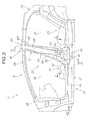
- the front floor cross member stiffener, the upper and lower center pillar stiffener members of the left and right center pillars and the roof arch are disposed in an annular configuration to thereby provide an annular framework, as viewed in front elevation of the vehicle compartment.
- the lower center pillar stiffener members of the left and right center pillars which are not among the members formed by the die quenching (hot stamping), are each a steel plate of a small strength (i.e., ordinary high-tensile steel plate).
- the lower center pillar stiffener member of ordinary high-tensile steel plate corresponding to the one side body, first deforms, ahead of others, toward beneath a seat cushion section provided within the passenger compartment, in response to which other elements connected to the lower center pillar stiffener member are advantageously induced to deform toward beneath the seat cushion section.
- the side sill stiffener member of each of the left and right side sills can achieve an increased strength against a load (impact) input to the front or rear surface of the vehicle.
- the side vehicle body structure of the present invention can achieve an increased strength of the vehicle body against loads (collision loads) input to the front, rear and side surfaces of the vehicle.
- each of the left and right center pillars includes an upper section formed in a closed sectional shape with the upper center pillar stiffener member and an inner center pillar member facing the passenger compartment and a lower section formed in a closed sectional shape with the lower center pillar stiffener member and the inner center pillar member, and the roof arch is fixedly joined at opposite end portions thereof to the inner center pillar members of the left and right center pillars via corner brackets.
- the lower center pillar stiffener member of the corresponding center pillar becomes a starting point of deformation to collapse toward the interior (hollow interior) of the closed sectional shape ahead of other elements.
- the lower center pillar stiffener member of each of the left and right center pillars overlaps a seat cushion section of a front seat disposed within the passenger compartment.
- the lower center pillar stiffener member corresponding to the one side body advantageously deforms toward beneath the seat cushion section.
- the front floor cross member is formed in a closed sectional shape with the front floor cross member stiffener and a front floor cross member body, and only the front floor cross member body is fixedly joined at each of opposite ends thereof to the inner side sill member that defines a closed sectional shape in conjunction with the side sill stiffener of a corresponding one of the left and right side sills. Further, opposite ends of the front floor cross member stiffener are each spaced from the inner side sill member of the corresponding side sill to form a space therebetween.
- each end portion of the front floor cross member body fixedly joined to the inner side sill member of one of the left and right side sills, is allowed to readily deform, which can thereby induce the lower center pillar stiffener member to deform toward beneath the seat cushion section.
- the side vehicle body structure of the present invention further comprises a partitioning and reinforcing member provided in each of the left and right side sills for partitioning and reinforcing the side sill.
- the input load can be dispersed to the partitioning and reinforcing member of the corresponding side sill, so that this arrangement can more reliably prevent collapsing deformation of the side sill.
- the partitioning and reinforcing member can transmit the input load to the end portion of the front floor cross member body via the inner side sill member without substantively attenuating the load, thereby more reliably promoting compressive deformation of the end portion of the front floor cross member body.
- this arrangement can prevent collapsing deformation of the hollow side sill into the interior of the side sill itself.
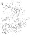
- FIG. 1 showing in perspective an embodiment of a side vehicle body structure of the present invention employed in a vehicle 11, in which a left side body 13 and right side body (not shown) of a vehicle body 12 are fixedly joined with each other via a front floor cross member 15 located thereunder and a roof arch 16 located thereover.
- the side vehicle body structure is constructed in substantial left-right symmetry about a centerline C ( Fig. 3 ) of the vehicle body 12; that is, the left side body 13 and the right side body are substantially symmetrical to each other about the longitudinal centerline C.
- the vehicle 11 which is for example a four-door, right-steering-wheel type vehicle, includes front and rear doorways 18 and 21 provided in the left side body 13, passenger compartment 22, and front and rear seats 24 and 25 provided in the passenger compartment 22.
- Reference numeral 35 represents a roof including the roof arch 16, and 36 represents a roof panel.
- the left side body 13 includes a side sill 27 constituting a lower frame of the front and rear doorways 18 and 21 and constituting lower end edges of the left and right side bodies, a front pillar 28, a roof side rail 29 constituting an upper frame of the front and rear doorways 18 and 21, a center pillar 31, and a rear pillar 32.
- the left side body 13 includes an outer side panel 33 ( Figs. 3 and 4 ) constituting an outer surface of the side sill 27, front pillar 28, center pillar 31 and rear pillar 32, only part of the outer side panel 33 is indicated by two-dot-dash line.
- the right side body (not shown) is constructed similar to the left side body 13.
- the side vehicle body structure includes the left side body 13 constituting a left side wall of the passenger compartment 22, the right side body constituting a right side wall of the passenger compartment 22, a right side wall of the passenger compartment 22, the front floor cross member 15 extending in a with (or left-right) direction of the vehicle to interconnect longitudinally-middle portions 41 of the side sills 27 of the left and right side bodies 13 (left and right side sills 27), and the roof arch 16 extending in the with (or left-right) direction of the vehicle to join together upper end portions 42 of the center pillars 31 of the left and right side bodies (i.e., left and right center pillars 31) extending upward from the middle portions 41.
- the roof arch 16, upper center pillar stiffener member 44 of a center pillar stiffener 43 ( Fig. 1 ) of the center pillars 31, side sill stiffener 45 of the side sill 27 and front floor cross member stiffener 46 of the front floor cross member 15 are each a super-high-tensile-strength workpiece formed by die quenching of a steel plate, i.e. by a die quench (or hot stamp) process in which a steel plate is heated and plastically formed with a die, attached to a press device, and simultaneously cooled or quenched by contact with the die to be thereby quenched (see Japanese Industrial Standards (JIS)).
- JIS Japanese Industrial Standards
- a lower center pillar stiffener member 47 which is the remaining part of the center pillar stiffener 43, is formed by cold pressing a steel plate, which has a strength smaller than a strength obtainable by die quenching of the steel plate.
- the front floor cross member stiffener 46, left and right center pillar stiffeners 47, upper and lower center pillar stiffener members 44 and 47 of the left and right center pillars 31 and roof arch 16 are arranged or disposed in an annular configuration as viewed in front elevation of the passenger compartment 22 (i.e., as shown in Fig. 3 ).
- the workpieces (hot stamped workpieces) obtained by the die quench (or hot stamp) process in the instant embodiment are each a workpiece of super-high-tensile-strength steel having a tensile strength of 980 Mpa or over that is greater than tensile strengths (e.g., 590 Mpa) of the lower center pillar stiffener member 47, inner center pillar member 48, front floor cross member 15 and inner side sill member 54.
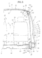
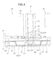
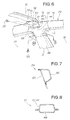
- the center pillar 31 has an upper section formed in a closed sectional shape with the upper center pillar stiffener member 44 and inner center pillar member 48, facing the passenger compartment 22, as shown in Fig. 8 , and a lower section formed in a closed sectional shape with the lower center pillar stiffener member 47 and inner center pillar member 48 as shown in Fig. 4 .
- the roof arch 16 are fixedly joined at its opposite end portions to the inner center pillar members 48 of the left and right center pillars 31 via corner brackets 51 with an inner roof side rail member 87 sandwiched between each of the inner center pillar members 48 and the corresponding corner bracket 51.
- the lower center pillar stiffener member 47 overlaps a seat cushion section 52 of the front seat 24 provided within the passenger compartment 22.
- the front floor cross member 15 has a closed sectional shape defined by the front floor cross member stiffener 46 and front floor cross member body 53 as shown in Fig. 11 , and only the front floor cross member body 53 is fixedly joined at each of its opposite ends to the inner side sill member 54 that defines a closed sectional shape ( Fig. 3 ) in conjunction with the side sill stiffener 45, as shown in Figs. 4 and 9 .
- the front floor cross member stiffener 46 is spaced from the inner side sill member 54 of each of the left and right side sills by a distance (average distance) E to define a space 56, as shown in Fig. 4 .
- a partitioning and reinforcing member 57 is provided within the side sill 27, as shown in Figs. 4 , 9 and 10 .
- the portioning and reinforcing member 57 includes an outer bulkhead 58, inner bulkhead 61, front bulkhead 62 and rear bulkhead 63.
- the side sill 27 comprises an outer side sill member 67, inner side sill member 54 and side sill stiffener 45 that is formed by the die quench (hot stamp) process.
- the side sill stiffener 45 is provided, along a substantially full length of the side sill 27, in an interior space (closed sectional shape), defined by the outer side sill member 67 and inner side sill member 54, in such a manner as to divide the interior space into two interior space regions, and the side sill stiffener 45 constitutes an intermediate layer of the side sill 27.
- An underbody 68 is fixedly joined to the inner side sill member 54.
- the front floor cross member 15 of the underbody 68 is fixedly joined to the left and right side sills 2 only at opposite end portions 53a and 53b ( Fig. 5 ) of the front floor cross member body 53.
- the opposite end portions 53a and 53b ( Fig. 5 ) of the front floor cross member body 53 are also opposite end portions of the front floor cross member 15. Further, the distance (average distance) E at each of the end portions 53a and 53b is intended to function as a collapsing region.
- front floor cross member body 53 has a channel cross-sectional shape, and opposite flanges 71, formed integrally with the body 53, are fixedly joined to the front floor cross member stiffener 46.
- the front floor cross member stiffener 46 has a generally band-like shape and has opposite joining margins 72 laid over and welded with the flanges 71 of the front floor cross member body 53. Each of opposite end surfaces 73 of the front floor cross member stiffener 46 is spaced from the longitudinally-middle portion 41 of the corresponding side sill 27 connected to the center pillar 31, rather than being joined to the side sill 27.
- Each of the left and right center pillars 31 comprises three main members: an outer center pillar member 75 of the outer side panel 33; the inner center pillar member 48; and the center pillar stiffener 43.
- the inner center pillar member 48 extends through the side sill 27.
- the center pillar stiffener 43 is provided in an interior space, defined by the outer center pillar member 75 and the inner center pillar member 48, in such a manner as to divide the interior space into two space regions and constitutes an intermediate layer of the center pillar 31. Further, the center pillar stiffener 43 has a hat-like or U sectional shape as shown in Figs. 4 , 8 and 10 and extends from the roof side rail 29 to the side sill 27 as shown in Fig. 3 . Further, the center pillar stiffener 43 comprises two members: the upper center pillar stiffener member 44 formed by the above-mentioned die quench (hot stamp) process; and the lower center pillar stiffener member 47.
- the lower center pillar stiffener member 47 has an upper-end joint section 78 laid over and joined to the outer surface of a lower end portion of the upper center pillar stiffener member 44, and a lower-end joint section 81 joined to the outer surface of the side sill 27.
- the upper center pillar stiffener member 44 has a lower-end joint section 83 joined with the lower center pillar stiffener member 47, and a roof joint section 84 joined to the roof side rail 29.
- the roof side rail 29 of the left and right side bodies 13 (i.e., left and right roof side rails 29) includes an outer roof side rail member 86 and an inner rood side rail member 87 that together define a closed sectional shape of the roof side rail 29 as shown in Figs. 3 and 7 .
- the roof arch 16 is fixedly connected at opposite ends to longitudinally-middle portions of the left and right rood side rails 29.
- the roof arch 16 has a channel sectional shape, and it has a fastening section 92 at one end portion 91 portion thereof for fastening thereto the corner bracket 51 and a similar fastening section 94 at another end portion 93 thereof.
- the one end portion 91 has an upper surface in generally the same plane as an upper surface of an end portion 43a of the center pillar stiffener 43 of the left center pillar.
- the other end portion 93 has an upper surface in generally the same plane as an upper surface of an end portion of the center pillar stiffener of the right center pillar.
- Each of the fastening sections 92 and 94 has a fastening hole 95 having a diameter corresponding to a diameter of a bolt 96.
- the roof side arch 16 is fixedly joined at each of the opposite end portions to the upper end portion 42 of the center pillar 31 and to the roof side rail 29 via the corner bracket 51.
- the corner bracket 51 which is of a plate shape, has a one-end fastening section 98 retained in face-to-face contact with the upper end portion 42 of the center pillar 31, and an other-end fastening section 101 retained in face-to-face contact with the roof arch 16.
- the partitioning and reinforcing member 57 comprises the above-mentioned outer bulkhead 58, inner bulkhead 61, front bulkhead 62 and rear bulkhead 63.
- the outer bulkhead 58 has a generally U sectional shape defined by a pair of opposed first and second partition sections 103 and 104 and a connection section 105 interconnecting the lower ends of the first and second partition sections 103 and 104.
- Each of the front and rear bulkheads 62 and 63 includes a body 111 fitted with inner wall surfaces of the side wall 27 in such a manner as to partition the interior of the side wall 27.
- the front seat 24 is a conventional separate-type seat which includes a driver's seat 114 and a front passenger's seat 115 provided separately from each other. As shown in Fig. 3 , the front passenger's seat 115 includes a seat cushion 52 and a seat back 116 attached to the seat cushion 52. The seat cushion 52 is fixed to the underbody 68, including the front floor cross member 15, via a slide device 117.
- the driver's seat 114 is constructed in generally the same manner as the front passenger's seat 115.
- the front seat 24 may be a bench seat type where the driver's seat 114 and front passenger's seat 115 are formed integrally with each other.
- the lower center pillar stiffener member 47 As a load is input from an external obstacle or object to the center pillar 31 of the left side body 13 as indicated by arrow a1, the lower center pillar stiffener member 47 having a strength smaller than that obtainable by the die quench process starts deforming, as a starting point of deformation, ahead of the others and thereby absorb the load.
- the upper center pillar stiffener member 44 extending continuously from the lower center pillar stiffener member 47 is a member (hot stamped member) obtained by the die quench (hot stamp) process.
- the upper center pillar stiffener member 44 has a greater tensile strength than the lower center pillar stiffener member 47 formed of high-tensile steel and hence is difficult to bend as compared to the lower center pillar stiffener member 47.
- the side sill 27 Simultaneously with deformation of the lower center pillar stiffener member 47 due to the input load, the side sill 27 transmits the external input load (arrow a1) to the one end portion 53a of the front floor cross member body 53 formed of high-tensile steel and extending inwardly from the side sill 27.
- the front floor cross member body 53 When the input load has been transmitted to the front floor cross member body 53, the front floor cross member body 53 starts deforming at the one end portion 53a and thereby absorbs the load.
- the front floor cross member stiffener 46 fixedly joined to the front floor cross member body 53 is a member (hot stamped member) obtained by the die quench process, it has a greater tensile strength than the front floor cross member body 53 formed of high-tensile steel and hence is difficult to bend (more specifically, difficult to buckle or compressively deform) as compared to the front floor cross member body 53. Thus, the impact is absorbed by the one end portion 53a positively deforming in response to the impact.
- the upper center pillar stiffener member 44 bends into the passenger compartment 22, but an amount of such bending of the upper center pillar stiffener member 44 is small. Because the upper center pillar stiffener member 44 is a member (hot stamped member) obtained by the die quench process, it has a greater tensile than high-tensile steel and hence is difficult to bend.
- the upper center pillar stiffener member 44 transmits the input load to the roof arch 16 extending continuously from an upper end portion of the upper center pillar stiffener member 44.
- the roof arch 16, to which the load has been transmitted as above, is also a hot stamped member that has a greater tensile than high-tensile steel and hence presents a small amount of compressive or buckling deformation.
- the side sill 27 disperses the input load by means of the hot-stamped side sill stiffener 45, and thus, it presents a small amount of compressive or buckling deformation.
- the side sill stiffener 45 has a greater tensile than high-tensile steel and hence is difficult to plastically deform.
- the side sill 27 is difficult to plastically deform because of the provision of the front floor cross member stiffener 46 of the front floor cross member 15. Similarly, when a collision load has been input from the rear of the vehicle 11, the side sill 27 is difficult to plastically deform.
- the instant embodiment of the side vehicle body structure in which the hot stamped members, excluding the lower center pillar stiffener member 47, are disposed or arranged in an annular configuration, can significantly increase the strength of the vehicle body 12 against loads from the front, rear and left and right sides of the vehicle 11.
- the lower center pillar stiffener member 47 is smaller in tensile strength than the upper center pillar stiffener member 44 and side sill stiffener 45 extending continuously from the lower center pillar stiffener member 47, and thus, as a load is input as indicated by arrow a1, the lower center pillar stiffener member 47 starts deforming toward the seat cushion section 52 of the front seat 24, i.e., starts being pressed into the passenger compartment 22.
- the side sill stiffener 45 deforms inwardly so that the input load is transmitted from the inner side sill member 54 to the front cross member body 53 via the partitioning and reinforcing member 57 as shown in Figs. 9 to 12 . In this case, the load is not transmitted directly to the front cross member stiffener 46 spaced part from the inner side sill member 54.
- the front cross member body 53 except its opposite end portions 53a and 53b, is reinforced by the front floor cross member stiffener 46 (hot stamped member).
- the one end portion 53a is easy to deform in response to the input load, which allows the lower center pillar stiffener member 47 to be more reliably deformed toward beneath the seat cushion section 52 as indicated by arrow a3.
- the side sill 27 operates to disperse the input load from the side sill stiffener 45 to the partitioning and reinforcing member 57 (outer bulkhead 58, inner bulkhead 61, front bulkhead 62 and rear bulkhead 63), so that the instant embodiment can prevent the side sill stiffener 45 from being inwardly collapsed.
- the side sill stiffener 45 transmits most of the input load to the front floor cross member 15 via the inner side sill member 54, collapsing of the end portion 53a of the front floor cross member body 53 can be promoted, as a result of which it is possible to prevent the hollow side sill 27 from being collapsed and deformed due to the input load.
- the embodiment of the side vehicle body structure of the present invention can advantageously eliminate a need for particularly shaping the lower center pillar stiffener member 47 and the opposite end portions 53a and 53b of the front floor cross member body 53 so as to provide a starting point of deformation.
- the embodiment of the side vehicle body structure of the present invention can eliminate a time and labor for particularly forming a portion, such as a fragile-shape portion, notch (V shape portion), hole or opening, which produces stress concentration.
- the hot stamp process can create super high-tensile-strength steel plates of 980 MPa or over. Although such super-high-tensile-strength steel plates can be applied to a vehicle body and reduce the weight of the vehicle body, it would be difficult to apply the super-high-tensile-strength steel plates to vehicle body members of complicated shapes.
- the high-tensile steel plates are applied only to members of relatively simple shapes, such as the roof arch, upper center pillar stiffener members, etc., and constitute an annular framework in combination with cold-pressed steel plates of about 590 Mpa.
- the present invention can provide a side vehicle body structure which can be manufactured at low cost and has a reduced weight and increased strength, and which can maintain an appropriate strength against frontal and lateral collisions.
- the side vehicle body structure of the present invention is well suited for application to bodies of automotive vehicles, particularly four-door automotive vehicles.
- Roof arch (16), upper center pillar stiffener members (44) of left and right center pillars (31), side sill stiffeners (45) of left and right side sills (27) and front floor cross member stiffener (46) are each formed by die quenching of a steel plate.
- Lower center pillar stiffener members (47) of left and right center pillars are each plastically formed of a steel plate having a strength smaller than a strength obtainable by die quenching of the steel plate.
- the front floor cross member stiffener (46), upper and lower center pillar stiffener members (44, 47) and roof arch (16) are arranged in an annular configuration, as viewed in front elevation of a vehicle compartment (22).
Landscapes
- Engineering & Computer Science (AREA)
- Chemical & Material Sciences (AREA)
- Combustion & Propulsion (AREA)
- Transportation (AREA)
- Mechanical Engineering (AREA)
- Body Structure For Vehicles (AREA)
Applications Claiming Priority (1)
| Application Number | Priority Date | Filing Date | Title |
|---|---|---|---|
| JP2010182324A JP5063757B2 (ja) | 2010-08-17 | 2010-08-17 | 車体側部構造 |
Publications (2)
| Publication Number | Publication Date |
|---|---|
| EP2420432A1 true EP2420432A1 (fr) | 2012-02-22 |
| EP2420432B1 EP2420432B1 (fr) | 2012-10-24 |
Family
ID=44514559
Family Applications (1)
| Application Number | Title | Priority Date | Filing Date |
|---|---|---|---|
| EP20110177647 Not-in-force EP2420432B1 (fr) | 2010-08-17 | 2011-08-16 | Structure latérale de carrosserie de véhicule |
Country Status (2)
| Country | Link |
|---|---|
| EP (1) | EP2420432B1 (fr) |
| JP (1) | JP5063757B2 (fr) |
Cited By (12)
| Publication number | Priority date | Publication date | Assignee | Title |
|---|---|---|---|---|
| US20140138988A1 (en) * | 2011-07-04 | 2014-05-22 | Honda Motor Co., Ltd. | Vehicle body structure and method for assembling vehicle body structure |
| US20150108788A1 (en) * | 2012-04-27 | 2015-04-23 | Nissan Motor Co., Ltd. | Structure against side impact |
| US20150123434A1 (en) * | 2012-04-27 | 2015-05-07 | Nissan Motor Co., Ltd. | Load transfer structure against side impact |
| CN106347475A (zh) * | 2016-11-25 | 2017-01-25 | 上汽通用五菱汽车股份有限公司 | C柱下接头的连接结构 |
| WO2017098303A1 (fr) * | 2015-12-09 | 2017-06-15 | Arcelormittal | Procédé pour produire une partie structurelle interne d'automobile comprenant des zones renforcées localisées |
| CN109204546A (zh) * | 2017-06-30 | 2019-01-15 | 比亚迪股份有限公司 | 车身结构及车辆 |
| US20190126988A1 (en) * | 2017-10-26 | 2019-05-02 | Toyota Jidosha Kabushiki Kaisha | Vehicle-body upper structure |
| US10406627B2 (en) | 2013-12-20 | 2019-09-10 | Nippon Steel Corporation | Resistance spot welding method |
| DE102018203104B4 (de) | 2017-03-03 | 2021-07-29 | Toyota Jidosha Kabushiki Kaisha | Fahrzeugheckstruktur |
| US11180008B2 (en) * | 2018-11-12 | 2021-11-23 | Honda Motor Co., Ltd. | Vehicle body structure of automobile |
| WO2022023443A3 (fr) * | 2020-07-29 | 2022-03-24 | Piëch Ip Ag | Véhicule à moteur de type modulaire et divers modules pour un véhicule à moteur de ce type |
| US11685444B2 (en) | 2019-10-04 | 2023-06-27 | Honda Motor Co., Ltd. | Vehicle body lateral section structure |
Families Citing this family (4)
| Publication number | Priority date | Publication date | Assignee | Title |
|---|---|---|---|---|
| JP5487236B2 (ja) * | 2012-04-05 | 2014-05-07 | 本田技研工業株式会社 | 自動車の車体側部構造 |
| CN103847800B (zh) * | 2012-12-03 | 2016-06-01 | 上汽通用五菱汽车股份有限公司 | 一种c柱下部接头结构 |
| JP6295466B2 (ja) * | 2014-07-11 | 2018-03-20 | トヨタ車体株式会社 | 車両のボディ構造 |
| JP6753302B2 (ja) | 2016-12-19 | 2020-09-09 | トヨタ自動車株式会社 | センタピラー構造 |
Citations (8)
| Publication number | Priority date | Publication date | Assignee | Title |
|---|---|---|---|---|
| US5671968A (en) * | 1994-08-31 | 1997-09-30 | Fuji Jukogyo Kabushiki Kaisha | Body structure for motor vehicle |
| US6086141A (en) * | 1994-08-31 | 2000-07-11 | Fuji Jukosyo Kabushiki Kaisha | Body structure for motor vehicle |
| US6139094A (en) * | 1998-05-04 | 2000-10-31 | Aluminum Company Of America | Rocker to pillar joint |
| US20010002760A1 (en) * | 1997-10-16 | 2001-06-07 | Gianfranco Gabbianelli | Door seal interface structure for a motor vehicle space frame |
| US20050023862A1 (en) * | 2003-08-01 | 2005-02-03 | Nissan Motor Co., Ltd. | Vehicle body structure |
| JP3637141B2 (ja) | 1996-03-19 | 2005-04-13 | 富士重工業株式会社 | 車両車体の側面衝突対策構造 |
| US20070102964A1 (en) * | 2005-11-04 | 2007-05-10 | Honda Motor Co., Ltd. | Vehicle body structure reinforced against side impact |
| DE102007053353A1 (de) * | 2007-10-30 | 2009-05-20 | Deutsches Zentrum für Luft- und Raumfahrt e.V. | Karosseriesäule für Fahrzeuge und Fahrzeugkarosserie |
Family Cites Families (6)
| Publication number | Priority date | Publication date | Assignee | Title |
|---|---|---|---|---|
| JP3120635B2 (ja) * | 1993-09-24 | 2000-12-25 | トヨタ自動車株式会社 | 自動車の車体下部構造 |
| JP3924856B2 (ja) * | 1997-08-19 | 2007-06-06 | マツダ株式会社 | 車両の車体構造 |
| JP3500626B2 (ja) * | 1999-01-29 | 2004-02-23 | マツダ株式会社 | 車両の車体構造 |
| JP2009143280A (ja) * | 2007-12-11 | 2009-07-02 | Toyota Motor Corp | 車体構造 |
| JP5119475B2 (ja) * | 2008-05-14 | 2013-01-16 | 新日鐵住金株式会社 | センターピラー補強部材及びその製造方法 |
| JP5407367B2 (ja) * | 2009-01-28 | 2014-02-05 | マツダ株式会社 | 車両の側部車体構造 |
-
2010
- 2010-08-17 JP JP2010182324A patent/JP5063757B2/ja not_active Expired - Fee Related
-
2011
- 2011-08-16 EP EP20110177647 patent/EP2420432B1/fr not_active Not-in-force
Patent Citations (8)
| Publication number | Priority date | Publication date | Assignee | Title |
|---|---|---|---|---|
| US5671968A (en) * | 1994-08-31 | 1997-09-30 | Fuji Jukogyo Kabushiki Kaisha | Body structure for motor vehicle |
| US6086141A (en) * | 1994-08-31 | 2000-07-11 | Fuji Jukosyo Kabushiki Kaisha | Body structure for motor vehicle |
| JP3637141B2 (ja) | 1996-03-19 | 2005-04-13 | 富士重工業株式会社 | 車両車体の側面衝突対策構造 |
| US20010002760A1 (en) * | 1997-10-16 | 2001-06-07 | Gianfranco Gabbianelli | Door seal interface structure for a motor vehicle space frame |
| US6139094A (en) * | 1998-05-04 | 2000-10-31 | Aluminum Company Of America | Rocker to pillar joint |
| US20050023862A1 (en) * | 2003-08-01 | 2005-02-03 | Nissan Motor Co., Ltd. | Vehicle body structure |
| US20070102964A1 (en) * | 2005-11-04 | 2007-05-10 | Honda Motor Co., Ltd. | Vehicle body structure reinforced against side impact |
| DE102007053353A1 (de) * | 2007-10-30 | 2009-05-20 | Deutsches Zentrum für Luft- und Raumfahrt e.V. | Karosseriesäule für Fahrzeuge und Fahrzeugkarosserie |
Cited By (20)
| Publication number | Priority date | Publication date | Assignee | Title |
|---|---|---|---|---|
| US9394018B2 (en) * | 2011-07-04 | 2016-07-19 | Honda Motor Co., Ltd. | Vehicle body structure and method for assembling vehicle body structure |
| US20140138988A1 (en) * | 2011-07-04 | 2014-05-22 | Honda Motor Co., Ltd. | Vehicle body structure and method for assembling vehicle body structure |
| US20150108788A1 (en) * | 2012-04-27 | 2015-04-23 | Nissan Motor Co., Ltd. | Structure against side impact |
| US20150123434A1 (en) * | 2012-04-27 | 2015-05-07 | Nissan Motor Co., Ltd. | Load transfer structure against side impact |
| US9327622B2 (en) * | 2012-04-27 | 2016-05-03 | Nissan Motor Co., Ltd. | Load transfer structure against side impact |
| US9327767B2 (en) * | 2012-04-27 | 2016-05-03 | Nissan Motor Co., Ltd. | Structure against side impact |
| US10406627B2 (en) | 2013-12-20 | 2019-09-10 | Nippon Steel Corporation | Resistance spot welding method |
| US11097329B2 (en) | 2015-12-09 | 2021-08-24 | Arcelormittal | Method for producing an inner automotive structural part comprising localized reinforced areas |
| WO2017098427A1 (fr) * | 2015-12-09 | 2017-06-15 | Arcelormittal | Procédé de production d'une pièce de structure automobile interne comprenant des zones renforcées localisées |
| WO2017098303A1 (fr) * | 2015-12-09 | 2017-06-15 | Arcelormittal | Procédé pour produire une partie structurelle interne d'automobile comprenant des zones renforcées localisées |
| RU2720387C2 (ru) * | 2015-12-09 | 2020-04-29 | Арселормиттал | Способ изготовления внутреннего элемента конструкции автомобиля, содержащего ограниченные усиленные участки |
| CN106347475A (zh) * | 2016-11-25 | 2017-01-25 | 上汽通用五菱汽车股份有限公司 | C柱下接头的连接结构 |
| CN106347475B (zh) * | 2016-11-25 | 2023-08-04 | 上汽通用五菱汽车股份有限公司 | C柱下接头的连接结构 |
| DE102018203104B4 (de) | 2017-03-03 | 2021-07-29 | Toyota Jidosha Kabushiki Kaisha | Fahrzeugheckstruktur |
| CN109204546A (zh) * | 2017-06-30 | 2019-01-15 | 比亚迪股份有限公司 | 车身结构及车辆 |
| US20190126988A1 (en) * | 2017-10-26 | 2019-05-02 | Toyota Jidosha Kabushiki Kaisha | Vehicle-body upper structure |
| US10933918B2 (en) * | 2017-10-26 | 2021-03-02 | Toyota Jidosha Kabushiki Kaisha | Vehicle-body upper structure |
| US11180008B2 (en) * | 2018-11-12 | 2021-11-23 | Honda Motor Co., Ltd. | Vehicle body structure of automobile |
| US11685444B2 (en) | 2019-10-04 | 2023-06-27 | Honda Motor Co., Ltd. | Vehicle body lateral section structure |
| WO2022023443A3 (fr) * | 2020-07-29 | 2022-03-24 | Piëch Ip Ag | Véhicule à moteur de type modulaire et divers modules pour un véhicule à moteur de ce type |
Also Published As
| Publication number | Publication date |
|---|---|
| JP2012040910A (ja) | 2012-03-01 |
| EP2420432B1 (fr) | 2012-10-24 |
| JP5063757B2 (ja) | 2012-10-31 |
Similar Documents
| Publication | Publication Date | Title |
|---|---|---|
| EP2420432B1 (fr) | Structure latérale de carrosserie de véhicule | |
| CN107031731B (zh) | 汽车的侧部车体构造 | |
| EP2105372B1 (fr) | Structure de cadre pour véhicule automobile, véhicule automobile fourni avec celle-ci et procédé pour fournir une structure de cadre | |
| JP4286884B2 (ja) | 自動車の車体構造 | |
| JP4384206B2 (ja) | 自動車の車体構造 | |
| JP4555210B2 (ja) | 自動車の車体構造 | |
| US7735902B2 (en) | Front structure of a motor vehicle | |
| JP6928719B2 (ja) | 自動車の車体構造 | |
| JP3783546B2 (ja) | 車両のサイドシル構造 | |
| AU705222B2 (en) | Front structure of car body, and method of absorbing impact by means of the front structure | |
| JP4151527B2 (ja) | 車体側面構造 | |
| CN210734286U (zh) | 车辆侧部构造 | |
| CN107792183B (zh) | 车辆的后部车体构造 | |
| JP6588972B2 (ja) | 自動車用の補強要素、補強要素およびドアアセンブリを製造するための方法 | |
| JP6308427B2 (ja) | 車体構造 | |
| WO2015025572A1 (fr) | Structure de montant central pour automobile | |
| JP2011037291A (ja) | フロントピラー構造 | |
| CN111017034B (zh) | 一种车架结构 | |
| US6983982B2 (en) | Front vehicle body structure | |
| KR102319323B1 (ko) | 차체 측부 구조 | |
| JP2007055414A (ja) | 車両用エネルギ吸収ビーム及び車両用ドア構造 | |
| CN111907601A (zh) | 中柱制造方法 | |
| US20150042124A1 (en) | Vehicle front structure | |
| CN100519310C (zh) | 一种可伸缩顶汽车前底板的布置结构 | |
| CN114572312A (zh) | 一种分片式前纵梁总成 |
Legal Events
| Date | Code | Title | Description |
|---|---|---|---|
| 17P | Request for examination filed |
Effective date: 20110816 |
|
| AK | Designated contracting states |
Kind code of ref document: A1 Designated state(s): AL AT BE BG CH CY CZ DE DK EE ES FI FR GB GR HR HU IE IS IT LI LT LU LV MC MK MT NL NO PL PT RO RS SE SI SK SM TR |
|
| AX | Request for extension of the european patent |
Extension state: BA ME |
|
| PUAI | Public reference made under article 153(3) epc to a published international application that has entered the european phase |
Free format text: ORIGINAL CODE: 0009012 |
|
| REG | Reference to a national code |
Ref country code: DE Ref legal event code: R079 Ref document number: 602011000349 Country of ref document: DE Free format text: PREVIOUS MAIN CLASS: B62D0025040000 Ipc: B62D0025020000 |
|
| GRAJ | Information related to disapproval of communication of intention to grant by the applicant or resumption of examination proceedings by the epo deleted |
Free format text: ORIGINAL CODE: EPIDOSDIGR1 |
|
| GRAP | Despatch of communication of intention to grant a patent |
Free format text: ORIGINAL CODE: EPIDOSNIGR1 |
|
| GRAP | Despatch of communication of intention to grant a patent |
Free format text: ORIGINAL CODE: EPIDOSNIGR1 |
|
| RIC1 | Information provided on ipc code assigned before grant |
Ipc: B62D 25/06 20060101ALI20120229BHEP Ipc: B62D 25/04 20060101ALI20120229BHEP Ipc: B62D 25/20 20060101ALI20120229BHEP Ipc: B62D 25/02 20060101AFI20120229BHEP |
|
| GRAS | Grant fee paid |
Free format text: ORIGINAL CODE: EPIDOSNIGR3 |
|
| RIN1 | Information on inventor provided before grant (corrected) |
Inventor name: IMAMURA, SHOGO Inventor name: MASUTA, NORIAKI Inventor name: HATTORI, HIROYUKI Inventor name: ASANO, SADAYUKI |
|
| GRAA | (expected) grant |
Free format text: ORIGINAL CODE: 0009210 |
|
| AK | Designated contracting states |
Kind code of ref document: B1 Designated state(s): AL AT BE BG CH CY CZ DE DK EE ES FI FR GB GR HR HU IE IS IT LI LT LU LV MC MK MT NL NO PL PT RO RS SE SI SK SM TR |
|
| REG | Reference to a national code |
Ref country code: GB Ref legal event code: FG4D |
|
| REG | Reference to a national code |
Ref country code: CH Ref legal event code: EP |
|
| REG | Reference to a national code |
Ref country code: AT Ref legal event code: REF Ref document number: 580753 Country of ref document: AT Kind code of ref document: T Effective date: 20121115 |
|
| REG | Reference to a national code |
Ref country code: IE Ref legal event code: FG4D |
|
| REG | Reference to a national code |
Ref country code: DE Ref legal event code: R096 Ref document number: 602011000349 Country of ref document: DE Effective date: 20121213 |
|
| REG | Reference to a national code |
Ref country code: AT Ref legal event code: MK05 Ref document number: 580753 Country of ref document: AT Kind code of ref document: T Effective date: 20121024 |
|
| REG | Reference to a national code |
Ref country code: NL Ref legal event code: VDEP Effective date: 20121024 |
|
| PG25 | Lapsed in a contracting state [announced via postgrant information from national office to epo] |
Ref country code: SE Free format text: LAPSE BECAUSE OF FAILURE TO SUBMIT A TRANSLATION OF THE DESCRIPTION OR TO PAY THE FEE WITHIN THE PRESCRIBED TIME-LIMIT Effective date: 20121024 Ref country code: FI Free format text: LAPSE BECAUSE OF FAILURE TO SUBMIT A TRANSLATION OF THE DESCRIPTION OR TO PAY THE FEE WITHIN THE PRESCRIBED TIME-LIMIT Effective date: 20121024 Ref country code: HR Free format text: LAPSE BECAUSE OF FAILURE TO SUBMIT A TRANSLATION OF THE DESCRIPTION OR TO PAY THE FEE WITHIN THE PRESCRIBED TIME-LIMIT Effective date: 20121024 Ref country code: NO Free format text: LAPSE BECAUSE OF FAILURE TO SUBMIT A TRANSLATION OF THE DESCRIPTION OR TO PAY THE FEE WITHIN THE PRESCRIBED TIME-LIMIT Effective date: 20130124 Ref country code: IS Free format text: LAPSE BECAUSE OF FAILURE TO SUBMIT A TRANSLATION OF THE DESCRIPTION OR TO PAY THE FEE WITHIN THE PRESCRIBED TIME-LIMIT Effective date: 20130224 Ref country code: NL Free format text: LAPSE BECAUSE OF FAILURE TO SUBMIT A TRANSLATION OF THE DESCRIPTION OR TO PAY THE FEE WITHIN THE PRESCRIBED TIME-LIMIT Effective date: 20121024 |
|
| PG25 | Lapsed in a contracting state [announced via postgrant information from national office to epo] |
Ref country code: LV Free format text: LAPSE BECAUSE OF FAILURE TO SUBMIT A TRANSLATION OF THE DESCRIPTION OR TO PAY THE FEE WITHIN THE PRESCRIBED TIME-LIMIT Effective date: 20121024 Ref country code: PT Free format text: LAPSE BECAUSE OF FAILURE TO SUBMIT A TRANSLATION OF THE DESCRIPTION OR TO PAY THE FEE WITHIN THE PRESCRIBED TIME-LIMIT Effective date: 20130225 Ref country code: SI Free format text: LAPSE BECAUSE OF FAILURE TO SUBMIT A TRANSLATION OF THE DESCRIPTION OR TO PAY THE FEE WITHIN THE PRESCRIBED TIME-LIMIT Effective date: 20121024 Ref country code: PL Free format text: LAPSE BECAUSE OF FAILURE TO SUBMIT A TRANSLATION OF THE DESCRIPTION OR TO PAY THE FEE WITHIN THE PRESCRIBED TIME-LIMIT Effective date: 20121024 Ref country code: GR Free format text: LAPSE BECAUSE OF FAILURE TO SUBMIT A TRANSLATION OF THE DESCRIPTION OR TO PAY THE FEE WITHIN THE PRESCRIBED TIME-LIMIT Effective date: 20130125 Ref country code: BE Free format text: LAPSE BECAUSE OF FAILURE TO SUBMIT A TRANSLATION OF THE DESCRIPTION OR TO PAY THE FEE WITHIN THE PRESCRIBED TIME-LIMIT Effective date: 20121024 |
|
| PG25 | Lapsed in a contracting state [announced via postgrant information from national office to epo] |
Ref country code: AT Free format text: LAPSE BECAUSE OF FAILURE TO SUBMIT A TRANSLATION OF THE DESCRIPTION OR TO PAY THE FEE WITHIN THE PRESCRIBED TIME-LIMIT Effective date: 20121024 |
|
| PG25 | Lapsed in a contracting state [announced via postgrant information from national office to epo] |
Ref country code: CZ Free format text: LAPSE BECAUSE OF FAILURE TO SUBMIT A TRANSLATION OF THE DESCRIPTION OR TO PAY THE FEE WITHIN THE PRESCRIBED TIME-LIMIT Effective date: 20121024 Ref country code: RS Free format text: LAPSE BECAUSE OF FAILURE TO SUBMIT A TRANSLATION OF THE DESCRIPTION OR TO PAY THE FEE WITHIN THE PRESCRIBED TIME-LIMIT Effective date: 20121024 Ref country code: SK Free format text: LAPSE BECAUSE OF FAILURE TO SUBMIT A TRANSLATION OF THE DESCRIPTION OR TO PAY THE FEE WITHIN THE PRESCRIBED TIME-LIMIT Effective date: 20121024 Ref country code: DK Free format text: LAPSE BECAUSE OF FAILURE TO SUBMIT A TRANSLATION OF THE DESCRIPTION OR TO PAY THE FEE WITHIN THE PRESCRIBED TIME-LIMIT Effective date: 20121024 Ref country code: EE Free format text: LAPSE BECAUSE OF FAILURE TO SUBMIT A TRANSLATION OF THE DESCRIPTION OR TO PAY THE FEE WITHIN THE PRESCRIBED TIME-LIMIT Effective date: 20121024 Ref country code: BG Free format text: LAPSE BECAUSE OF FAILURE TO SUBMIT A TRANSLATION OF THE DESCRIPTION OR TO PAY THE FEE WITHIN THE PRESCRIBED TIME-LIMIT Effective date: 20130124 |
|
| PG25 | Lapsed in a contracting state [announced via postgrant information from national office to epo] |
Ref country code: IT Free format text: LAPSE BECAUSE OF FAILURE TO SUBMIT A TRANSLATION OF THE DESCRIPTION OR TO PAY THE FEE WITHIN THE PRESCRIBED TIME-LIMIT Effective date: 20121024 Ref country code: RO Free format text: LAPSE BECAUSE OF FAILURE TO SUBMIT A TRANSLATION OF THE DESCRIPTION OR TO PAY THE FEE WITHIN THE PRESCRIBED TIME-LIMIT Effective date: 20121024 |
|
| PLBE | No opposition filed within time limit |
Free format text: ORIGINAL CODE: 0009261 |
|
| STAA | Information on the status of an ep patent application or granted ep patent |
Free format text: STATUS: NO OPPOSITION FILED WITHIN TIME LIMIT |
|
| 26N | No opposition filed |
Effective date: 20130725 |
|
| PG25 | Lapsed in a contracting state [announced via postgrant information from national office to epo] |
Ref country code: ES Free format text: LAPSE BECAUSE OF FAILURE TO SUBMIT A TRANSLATION OF THE DESCRIPTION OR TO PAY THE FEE WITHIN THE PRESCRIBED TIME-LIMIT Effective date: 20130204 |
|
| REG | Reference to a national code |
Ref country code: DE Ref legal event code: R097 Ref document number: 602011000349 Country of ref document: DE Effective date: 20130725 |
|
| PG25 | Lapsed in a contracting state [announced via postgrant information from national office to epo] |
Ref country code: CY Free format text: LAPSE BECAUSE OF FAILURE TO SUBMIT A TRANSLATION OF THE DESCRIPTION OR TO PAY THE FEE WITHIN THE PRESCRIBED TIME-LIMIT Effective date: 20121024 |
|
| PG25 | Lapsed in a contracting state [announced via postgrant information from national office to epo] |
Ref country code: MC Free format text: LAPSE BECAUSE OF FAILURE TO SUBMIT A TRANSLATION OF THE DESCRIPTION OR TO PAY THE FEE WITHIN THE PRESCRIBED TIME-LIMIT Effective date: 20121024 |
|
| REG | Reference to a national code |
Ref country code: IE Ref legal event code: MM4A |
|
| PG25 | Lapsed in a contracting state [announced via postgrant information from national office to epo] |
Ref country code: LT Free format text: LAPSE BECAUSE OF FAILURE TO SUBMIT A TRANSLATION OF THE DESCRIPTION OR TO PAY THE FEE WITHIN THE PRESCRIBED TIME-LIMIT Effective date: 20121024 Ref country code: IE Free format text: LAPSE BECAUSE OF NON-PAYMENT OF DUE FEES Effective date: 20130816 |
|
| REG | Reference to a national code |
Ref country code: CH Ref legal event code: PL |
|
| PG25 | Lapsed in a contracting state [announced via postgrant information from national office to epo] |
Ref country code: LI Free format text: LAPSE BECAUSE OF NON-PAYMENT OF DUE FEES Effective date: 20140831 Ref country code: CH Free format text: LAPSE BECAUSE OF NON-PAYMENT OF DUE FEES Effective date: 20140831 |
|
| REG | Reference to a national code |
Ref country code: DE Ref legal event code: R084 Ref document number: 602011000349 Country of ref document: DE |
|
| PG25 | Lapsed in a contracting state [announced via postgrant information from national office to epo] |
Ref country code: SM Free format text: LAPSE BECAUSE OF FAILURE TO SUBMIT A TRANSLATION OF THE DESCRIPTION OR TO PAY THE FEE WITHIN THE PRESCRIBED TIME-LIMIT Effective date: 20121024 |
|
| REG | Reference to a national code |
Ref country code: GB Ref legal event code: 746 Effective date: 20150507 |
|
| REG | Reference to a national code |
Ref country code: DE Ref legal event code: R084 Ref document number: 602011000349 Country of ref document: DE Effective date: 20150505 |
|
| REG | Reference to a national code |
Ref country code: FR Ref legal event code: PLFP Year of fee payment: 5 |
|
| PG25 | Lapsed in a contracting state [announced via postgrant information from national office to epo] |
Ref country code: MT Free format text: LAPSE BECAUSE OF FAILURE TO SUBMIT A TRANSLATION OF THE DESCRIPTION OR TO PAY THE FEE WITHIN THE PRESCRIBED TIME-LIMIT Effective date: 20121024 Ref country code: TR Free format text: LAPSE BECAUSE OF FAILURE TO SUBMIT A TRANSLATION OF THE DESCRIPTION OR TO PAY THE FEE WITHIN THE PRESCRIBED TIME-LIMIT Effective date: 20121024 |
|
| PG25 | Lapsed in a contracting state [announced via postgrant information from national office to epo] |
Ref country code: HU Free format text: LAPSE BECAUSE OF FAILURE TO SUBMIT A TRANSLATION OF THE DESCRIPTION OR TO PAY THE FEE WITHIN THE PRESCRIBED TIME-LIMIT; INVALID AB INITIO Effective date: 20110816 Ref country code: LU Free format text: LAPSE BECAUSE OF NON-PAYMENT OF DUE FEES Effective date: 20130816 Ref country code: MK Free format text: LAPSE BECAUSE OF FAILURE TO SUBMIT A TRANSLATION OF THE DESCRIPTION OR TO PAY THE FEE WITHIN THE PRESCRIBED TIME-LIMIT Effective date: 20121024 |
|
| PGFP | Annual fee paid to national office [announced via postgrant information from national office to epo] |
Ref country code: GB Payment date: 20150812 Year of fee payment: 5 |
|
| PGFP | Annual fee paid to national office [announced via postgrant information from national office to epo] |
Ref country code: FR Payment date: 20150629 Year of fee payment: 5 |
|
| GBPC | Gb: european patent ceased through non-payment of renewal fee |
Effective date: 20160816 |
|
| REG | Reference to a national code |
Ref country code: FR Ref legal event code: ST Effective date: 20170428 |
|
| PG25 | Lapsed in a contracting state [announced via postgrant information from national office to epo] |
Ref country code: FR Free format text: LAPSE BECAUSE OF NON-PAYMENT OF DUE FEES Effective date: 20160831 Ref country code: GB Free format text: LAPSE BECAUSE OF NON-PAYMENT OF DUE FEES Effective date: 20160816 |
|
| PGFP | Annual fee paid to national office [announced via postgrant information from national office to epo] |
Ref country code: DE Payment date: 20170808 Year of fee payment: 7 |
|
| PG25 | Lapsed in a contracting state [announced via postgrant information from national office to epo] |
Ref country code: AL Free format text: LAPSE BECAUSE OF FAILURE TO SUBMIT A TRANSLATION OF THE DESCRIPTION OR TO PAY THE FEE WITHIN THE PRESCRIBED TIME-LIMIT Effective date: 20121024 |
|
| REG | Reference to a national code |
Ref country code: DE Ref legal event code: R119 Ref document number: 602011000349 Country of ref document: DE |
|
| PG25 | Lapsed in a contracting state [announced via postgrant information from national office to epo] |
Ref country code: DE Free format text: LAPSE BECAUSE OF NON-PAYMENT OF DUE FEES Effective date: 20190301 |