EP2418183B1 - Verfahren zur Härtung beschichteter Glasfasern mit erhöhter UVLED-Intensität - Google Patents
Verfahren zur Härtung beschichteter Glasfasern mit erhöhter UVLED-Intensität Download PDFInfo
- Publication number
- EP2418183B1 EP2418183B1 EP11176947.7A EP11176947A EP2418183B1 EP 2418183 B1 EP2418183 B1 EP 2418183B1 EP 11176947 A EP11176947 A EP 11176947A EP 2418183 B1 EP2418183 B1 EP 2418183B1
- Authority
- EP
- European Patent Office
- Prior art keywords
- uvled
- source
- curing
- array
- sources
- Prior art date
- Legal status (The legal status is an assumption and is not a legal conclusion. Google has not performed a legal analysis and makes no representation as to the accuracy of the status listed.)
- Active
Links
- 239000003365 glass fiber Substances 0.000 title claims description 105
- 238000000034 method Methods 0.000 title claims description 28
- 238000000576 coating method Methods 0.000 claims description 81
- 230000005855 radiation Effects 0.000 claims description 67
- 239000011248 coating agent Substances 0.000 claims description 58
- 230000008859 change Effects 0.000 claims description 7
- 230000004044 response Effects 0.000 claims description 7
- 230000003247 decreasing effect Effects 0.000 claims description 3
- 238000001723 curing Methods 0.000 description 112
- 239000013307 optical fiber Substances 0.000 description 57
- 230000001681 protective effect Effects 0.000 description 22
- 230000005670 electromagnetic radiation Effects 0.000 description 17
- QSHDDOUJBYECFT-UHFFFAOYSA-N mercury Chemical compound [Hg] QSHDDOUJBYECFT-UHFFFAOYSA-N 0.000 description 17
- 229910052753 mercury Inorganic materials 0.000 description 17
- 239000011247 coating layer Substances 0.000 description 12
- 239000001301 oxygen Substances 0.000 description 9
- 229910052760 oxygen Inorganic materials 0.000 description 9
- 230000008569 process Effects 0.000 description 9
- 238000010521 absorption reaction Methods 0.000 description 8
- QVGXLLKOCUKJST-UHFFFAOYSA-N atomic oxygen Chemical compound [O] QVGXLLKOCUKJST-UHFFFAOYSA-N 0.000 description 7
- 239000000835 fiber Substances 0.000 description 7
- 239000010410 layer Substances 0.000 description 7
- IJGRMHOSHXDMSA-UHFFFAOYSA-N Atomic nitrogen Chemical compound N#N IJGRMHOSHXDMSA-UHFFFAOYSA-N 0.000 description 6
- 239000007789 gas Substances 0.000 description 5
- 238000003491 array Methods 0.000 description 4
- 239000010453 quartz Substances 0.000 description 4
- VYPSYNLAJGMNEJ-UHFFFAOYSA-N silicon dioxide Inorganic materials O=[Si]=O VYPSYNLAJGMNEJ-UHFFFAOYSA-N 0.000 description 4
- 239000006227 byproduct Substances 0.000 description 3
- 230000001186 cumulative effect Effects 0.000 description 3
- 230000000694 effects Effects 0.000 description 3
- 239000011521 glass Substances 0.000 description 3
- 239000000203 mixture Substances 0.000 description 3
- 229910052757 nitrogen Inorganic materials 0.000 description 3
- 238000003848 UV Light-Curing Methods 0.000 description 2
- XAGFODPZIPBFFR-UHFFFAOYSA-N aluminium Chemical compound [Al] XAGFODPZIPBFFR-UHFFFAOYSA-N 0.000 description 2
- 229910052782 aluminium Inorganic materials 0.000 description 2
- 230000005540 biological transmission Effects 0.000 description 2
- UHESRSKEBRADOO-UHFFFAOYSA-N ethyl carbamate;prop-2-enoic acid Chemical compound OC(=O)C=C.CCOC(N)=O UHESRSKEBRADOO-UHFFFAOYSA-N 0.000 description 2
- 238000012681 fiber drawing Methods 0.000 description 2
- 238000011065 in-situ storage Methods 0.000 description 2
- 239000000463 material Substances 0.000 description 2
- 239000000178 monomer Substances 0.000 description 2
- 238000013021 overheating Methods 0.000 description 2
- 238000006116 polymerization reaction Methods 0.000 description 2
- 238000001228 spectrum Methods 0.000 description 2
- PSGCQDPCAWOCSH-UHFFFAOYSA-N (4,7,7-trimethyl-3-bicyclo[2.2.1]heptanyl) prop-2-enoate Chemical compound C1CC2(C)C(OC(=O)C=C)CC1C2(C)C PSGCQDPCAWOCSH-UHFFFAOYSA-N 0.000 description 1
- 229910001369 Brass Inorganic materials 0.000 description 1
- RYGMFSIKBFXOCR-UHFFFAOYSA-N Copper Chemical compound [Cu] RYGMFSIKBFXOCR-UHFFFAOYSA-N 0.000 description 1
- 239000010951 brass Substances 0.000 description 1
- 238000005253 cladding Methods 0.000 description 1
- 239000008199 coating composition Substances 0.000 description 1
- 239000002826 coolant Substances 0.000 description 1
- 238000001816 cooling Methods 0.000 description 1
- 229910052802 copper Inorganic materials 0.000 description 1
- 239000010949 copper Substances 0.000 description 1
- 230000008878 coupling Effects 0.000 description 1
- 238000010168 coupling process Methods 0.000 description 1
- 238000005859 coupling reaction Methods 0.000 description 1
- 230000002939 deleterious effect Effects 0.000 description 1
- 239000003085 diluting agent Substances 0.000 description 1
- 239000006185 dispersion Substances 0.000 description 1
- 238000005516 engineering process Methods 0.000 description 1
- 238000007380 fibre production Methods 0.000 description 1
- 210000002196 fr. b Anatomy 0.000 description 1
- 210000003918 fraction a Anatomy 0.000 description 1
- 230000004927 fusion Effects 0.000 description 1
- 238000010438 heat treatment Methods 0.000 description 1
- 239000011261 inert gas Substances 0.000 description 1
- 239000007788 liquid Substances 0.000 description 1
- 238000004519 manufacturing process Methods 0.000 description 1
- 239000011159 matrix material Substances 0.000 description 1
- VSQYNPJPULBZKU-UHFFFAOYSA-N mercury xenon Chemical compound [Xe].[Hg] VSQYNPJPULBZKU-UHFFFAOYSA-N 0.000 description 1
- 230000003287 optical effect Effects 0.000 description 1
- 239000004033 plastic Substances 0.000 description 1
- 239000002244 precipitate Substances 0.000 description 1
- 239000000047 product Substances 0.000 description 1
- 230000001737 promoting effect Effects 0.000 description 1
- 238000004088 simulation Methods 0.000 description 1
- 229910001220 stainless steel Inorganic materials 0.000 description 1
- 239000010935 stainless steel Substances 0.000 description 1
- 230000000153 supplemental effect Effects 0.000 description 1
- 239000002699 waste material Substances 0.000 description 1
- XLYOFNOQVPJJNP-UHFFFAOYSA-N water Substances O XLYOFNOQVPJJNP-UHFFFAOYSA-N 0.000 description 1
Images


Classifications
-
- C—CHEMISTRY; METALLURGY
- C03—GLASS; MINERAL OR SLAG WOOL
- C03C—CHEMICAL COMPOSITION OF GLASSES, GLAZES OR VITREOUS ENAMELS; SURFACE TREATMENT OF GLASS; SURFACE TREATMENT OF FIBRES OR FILAMENTS MADE FROM GLASS, MINERALS OR SLAGS; JOINING GLASS TO GLASS OR OTHER MATERIALS
- C03C25/00—Surface treatment of fibres or filaments made from glass, minerals or slags
- C03C25/62—Surface treatment of fibres or filaments made from glass, minerals or slags by application of electric or wave energy; by particle radiation or ion implantation
- C03C25/6206—Electromagnetic waves
- C03C25/6226—Ultraviolet
-
- C—CHEMISTRY; METALLURGY
- C03—GLASS; MINERAL OR SLAG WOOL
- C03C—CHEMICAL COMPOSITION OF GLASSES, GLAZES OR VITREOUS ENAMELS; SURFACE TREATMENT OF GLASS; SURFACE TREATMENT OF FIBRES OR FILAMENTS MADE FROM GLASS, MINERALS OR SLAGS; JOINING GLASS TO GLASS OR OTHER MATERIALS
- C03C25/00—Surface treatment of fibres or filaments made from glass, minerals or slags
- C03C25/10—Coating
- C03C25/12—General methods of coating; Devices therefor
-
- B—PERFORMING OPERATIONS; TRANSPORTING
- B05—SPRAYING OR ATOMISING IN GENERAL; APPLYING FLUENT MATERIALS TO SURFACES, IN GENERAL
- B05D—PROCESSES FOR APPLYING FLUENT MATERIALS TO SURFACES, IN GENERAL
- B05D3/00—Pretreatment of surfaces to which liquids or other fluent materials are to be applied; After-treatment of applied coatings, e.g. intermediate treating of an applied coating preparatory to subsequent applications of liquids or other fluent materials
- B05D3/06—Pretreatment of surfaces to which liquids or other fluent materials are to be applied; After-treatment of applied coatings, e.g. intermediate treating of an applied coating preparatory to subsequent applications of liquids or other fluent materials by exposure to radiation
- B05D3/061—Pretreatment of surfaces to which liquids or other fluent materials are to be applied; After-treatment of applied coatings, e.g. intermediate treating of an applied coating preparatory to subsequent applications of liquids or other fluent materials by exposure to radiation using U.V.
- B05D3/065—After-treatment
- B05D3/067—Curing or cross-linking the coating
-
- B—PERFORMING OPERATIONS; TRANSPORTING
- B05—SPRAYING OR ATOMISING IN GENERAL; APPLYING FLUENT MATERIALS TO SURFACES, IN GENERAL
- B05D—PROCESSES FOR APPLYING FLUENT MATERIALS TO SURFACES, IN GENERAL
- B05D2203/00—Other substrates
- B05D2203/30—Other inorganic substrates, e.g. ceramics, silicon
- B05D2203/35—Glass
-
- B—PERFORMING OPERATIONS; TRANSPORTING
- B05—SPRAYING OR ATOMISING IN GENERAL; APPLYING FLUENT MATERIALS TO SURFACES, IN GENERAL
- B05D—PROCESSES FOR APPLYING FLUENT MATERIALS TO SURFACES, IN GENERAL
- B05D2256/00—Wires or fibres
Definitions
- the present invention embraces an apparatus and a method for curing coatings on drawn glass fibers.
- Glass fibers are often protected from external forces with one or more coating layers.
- two or more layers of coatings are applied during the optical-fiber drawing process (i.e., whereby a glass fiber is drawn from an optical preform in a drawing tower).
- a softer inner coating layer typically helps to protect the glass fiber from microbending.
- a harder outer coating layer typically is used to provide additional protection and to facilitate handling of the glass fiber.
- the coating layers may be cured, for example, using heat or ultraviolet (UV) light.
- UV curing requires that the coated glass fiber be exposed to high intensity UV radiation. Curing time can be reduced by exposing the coating to higher intensity UV radiation. Reducing curing time is particularly desirable to permit an increase in fiber drawing line speeds and thus optical-fiber production rates.
- Mercury lamps e.g., high-pressure mercury lamps or mercury xenon lamps
- mercury lamps are commonly used to generate the UV radiation needed for UV curing.
- One downside of using mercury lamps is that mercury lamps require a significant amount of power to generate sufficiently intense UV radiation.
- UV lamps used to cure a single coated fiber i.e., one polymeric coating
- mercury lamps Another shortcoming of mercury lamps is that much of the energy used for powering mercury lamps is emitted not as UV radiation but rather as heat. Accordingly, mercury lamps must be cooled ( e . g ., using a heat exchanger) to prevent overheating. In addition, the undesirable heat generated by the mercury lamps may slow the rate at which the optical-fiber coatings cure.
- mercury lamps generate a wide spectrum of electromagnetic radiation, such as electromagnetic radiation having wavelengths of less than 200 nanometers and greater than 700 nanometers ( i . e ., infrared light).
- electromagnetic radiation having wavelengths of between about 300 nanometers and 400 nanometers is useful for curing UV coatings.
- much of the electromagnetic radiation generated by mercury bulbs is wasted ( e . g ., 90 percent or more).
- glass fibers typically possess a diameter of about 125 microns or less, which, of course, is much smaller than the mercury bulbs. Consequently, most of the UV radiation emitted by the mercury lamps does not reach the glass fiber's uncured coating ( i . e ., the energy is wasted).
- UVLEDs to cure glass-fiber coatings as an alternative to conventional mercury lamps. UVLEDs typically require significantly less energy and correspondingly generate much less heat energy than conventional UV lamps.
- U.S. Patent No. 7,022,382 discloses the use of UV lasers (e.g., continuous or pulsed lasers) for curing optical-fiber coatings.
- UV lasers e.g., continuous or pulsed lasers
- US 2005/0222295 , US 2010/0183821 and US 2003/0026919 disclose the use of ultraviolet light emitting diodes (UVLEDs) for curing optical-fiber coatings.
- UVLEDs ultraviolet light emitting diodes
- the present invention relates to a method of curing a coating on a glass according to claims 1-7.
- the coating is evenly cured as the glass fiber passes through the cavity.
- the output of each UVLED source in the first UVLED array defines a pulse train.
- each of the UVLED sources in the first UVLED array are driven at substantially the same current.
- At least two of the UVLED sources in the first UVLED array are driven at different currents.
- the maximum output intensity x n (t) max of each UVLED source in the first UVLED array is substantially the same.
- the maximum output intensities x n (t) max are different.
- the output x n (t) of each UVLED source in the first UVLED array defines a pulse train with a duty cycle equal to A/B; each UVLED source in the first UVLED array has substantially the same maximum output intensity x n (t) max and substantially the same minimum output intensity x n (t) min ; the first UVLED array has B UVLED sources; and x total (t,v f ) ⁇ A(x n (t) max + x n (t) min ).
- said method comprises the step of adjusting the phase of the output of at least one UVLED source in response to a change in the line speed v f of the glass fiber so that x total (t,v f ) has a substantially constant value for a given line speed.
- said method comprises increasing the output intensity of the UVLED sources in response to an increase in the line speed v f of the glass fiber.
- said method comprises decreasing the output intensity of the UVLED sources in response to a decrease in the line speed v f of the glass fiber.
- said method comprises the step of driving a UVLED source in the first UVLED array at a current that is greater than the UVLED source's maximum rated current, the UVLED source having a maximum output intensity x n (t) max greater than could be achieved if the UVLED source was driven at its maximum rated current.
- the apparatus for curing a coated glass fiber comprises a cavity defining a curing axis; and a first UVLED array positioned within said cavity, said first UVLED array comprising a plurality of UVLED sources; wherein each UVLED source in said first UVLED array has an oscillating output x n (t) of UV radiation having a maximum output intensity x n (t) max and a minimum output intensity x n (t) min , each UVLED source having a maximum output intensity x n (t) max that is greater than can be achieved by driving each UVLED source at its maximum rated current; wherein at least two of said UVLED sources in said first UVLED array have oscillating outputs of UV radiation that are out of phase with one another.
- said apparatus comprises a controller electrically connected to said first UVLED array; wherein said controller is capable of adjusting the output intensity and/or phase of the oscillating outputs of said UVLED sources in said first UVLED array.
- each said UVLED source in said first UVLED array has substantially the same maximum output intensity x n (t) max .
- At least two of said UVLED sources in said first UVLED array have different maximum output intensities x n (t) max .
- the output x n (t) of each said UVLED source in said first UVLED array defines a pulse train with a duty cycle equal to A/B; each UVLED source in said first UVLED array has substantially the same maximum output intensity x n (t) max and substantially the same minimum output intensity x n (t) min ; said first UVLED array has B UVLED sources; and x total (t,v f ) ⁇ A(x n (t) max + x n (t) min ).
- each said UVLED source in said first UVLED array defines a pulse train.
- said apparatus comprises a second UVLED array positioned within said cavity, said second UVLED array comprising a plurality of UVLED sources; wherein each UVLED source in said second UVLED array has an oscillating output y n (t) of UV radiation having a maximum output intensity y n (t) max and a minimum output intensity y n (t) min , each UVLED source having a maximum output intensity y n (t) max that is greater than can be achieved by driving each UVLED source at its maximum rated current; and wherein the maximum output intensity y n (t) max of at least one of said UVLED sources in said second UVLED array is different from the maximum output intensity x n (t) max of at least one of said UVLED sources in said first UVLED array.
- said apparatus comprises a controller electrically connected to said first UVLED array; wherein said controller is capable of adjusting the output intensity and/or phase of the oscillating outputs of said UVLED sources in said first UVLED array.
- each said UVLED source in said first UVLED array has substantially the same maximum output intensity x n (t) max .
- At least two of said UVLED sources in said first UVLED array have different maximum output intensities x n (t) max .
- the output x n (t) of each said UVLED source in said first UVLED array defines a pulse train with a duty cycle equal to A/B; each UVLED source in said first UVLED array has substantially the same maximum output intensity x n (t) max and substantially the same minimum output intensity x n (t) min ; said first UVLED array has B UVLED sources; and x total (t,v f ) ⁇ A(x n (t) max + x n (t) min ).
- each said UVLED source in said first UVLED array defines a pulse train.
- a UVLED source in said first UVLED array has a maximum output intensity x n (t) max that is greater than could be achieved if the UVLED source was driven at its maximum rated current.
- the present invention embraces a UVLED apparatus for curing in situ optical-fiber coatings (i.e., on a glass fiber).
- An exemplary apparatus for curing a coated glass fiber includes a cavity that defines a curing axis.
- a first UVLED array is positioned within the cavity.
- the first UVLED array includes a plurality of UVLED sources, each of which has a variable ( e . g ., oscillating) output x n (t) of UV radiation having a maximum output intensity x n (t) max and a minimum output intensity x n (t) min .
- the maximum output intensity x n (t) max of each of the UVLED sources is greater than can be achieved by driving each UVLED source at its respective maximum rated current.
- at least two of the UVLED sources have oscillating outputs of UV radiation that are out of phase with one another.
- the apparatus includes a controller that is capable of adjusting the intensity and/or phase of the oscillating outputs of the UVLED sources.
- the present invention embraces a method of curing a coating on a glass fiber.
- a glass fiber having an incompletely cured coating is passed at a line speed v f through a cavity and along a curing axis that is defined by the cavity.
- a plurality of UVLEDs that define a first UVLED array are driven at a current that is greater than the maximum rated current of the UVLED sources.
- Each UVLED source has an oscillating output x n (t) of UV radiation having a maximum output intensity x n (t) max and a minimum output intensity x n (t) min .
- the maximum output intensity x n (t) max of each of the UVLED sources is typically greater than could be achieved if each UVLED source was driven at its maximum rated current.
- UV radiation from the first UVLED array is emitted (e.g., into the cavity) to promote the curing of the glass-fiber coating.
- the present invention embraces an apparatus for curing glass-fiber coatings (e . g ., primary coatings, secondary coatings, and/or tertiary ink layers).
- the apparatus typically employs one or more UVLED arrays.
- each UVLED array has a plurality of UVLED sources that are capable of being driven beyond their normal operating current (e . g ., overdriven beyond a UVLED source's maximum rated current).
- the apparatus 10 for curing glass-fiber coatings includes a UVLED array 11a (denoted by a dotted circle) positioned within a cavity 12 ( e . g ., a substantially cylindrical cavity).
- the interior of the cavity 12 defines a curing space.
- the curing space defines a curing axis 13 along which a drawn glass fiber passes during the curing process.
- the UVLED array 11a includes a plurality of UVLED sources 14a.
- a mounting plate 15 may be employed to provide structural support for the UVLED sources 14a.
- Figure 1 depicts the UVLED array 11a having two UVLED sources 14a.
- each UVLED source is formed from a single light emitting diode. That said, it is within the scope of the present invention to employ a plurality of small light emitting diodes to form each UVLED source.
- each UVLED source (e . g ., a single UVLED or a plurality of discrete UVLEDs) is overdriven to achieve a higher-than-normal output intensity.
- each UVLED source is typically driven at a higher-than-rated power and current (e.g., higher than its normal operating current) so that each UVLED source has a maximum output intensity that is greater than could be achieved using a UVLED source's maximum rated current.
- a UVLED source may be driven at a current 2-4 times its maximum rated current (e.g., three times its maximum rated current). For some UVLED sources, a three-fold increase in current results in up to an eight-fold increase in UV-radiation output intensity.
- a device's maximum rated current is the maximum current that the device can continuously carry, while remaining within its temperature rating.
- each UVLED source is typically driven at a higher-than-rated current, each UVLED source is typically driven at its normal operating voltage.
- the cure rate of an optical-fiber coating depends not only on the total UV radiation dosage, but also on the intensity of the UV radiation to which the coating is exposed. As will be appreciated by those having ordinary skill in the art, it has been observed that an increase in the intensity of UV radiation results in a nonlinear (e.g., squared) increase in the cure rate of a coating. By overdriving UVLED sources, the cure rate of optical-fiber coatings can be increased, thereby enabling higher line speeds.
- UVLED sources Relative to other UV radiation sources (e . g ., mercury lamps), UVLED sources typically generate a smaller amount of heat energy. That said, each UVLED source may produce increased heat as a result of being overdriven. High temperatures may cause problems for the UVLED sources, therefore, dissipating heat generated by each UVLED source is important for a number of reasons. First, excessive heat may slow the rate at which optical-fiber coatings cure. Furthermore, excessive heat can cause the temperature of the UVLED source to rise, which can reduce UV-radiation output. Indeed, continuous high-temperature exposure can dramatically reduce the lifetime of a UVLED source ( e . g ., by permanently damaging the UVLED source).
- a heat sink 16 may be located behind each UVLED source 14a ( e . g ., opposite the portion of the UVLED source 14a that emits UV radiation).
- the heat sink 16 may be one-inch square, for example, although other heat sink shapes and sizes are within the scope of the present invention.
- the heat sink may be formed of a material suitable for conducting heat (e.g., brass, aluminum, or copper).
- Exemplary heat sinks may include fins or other protrusions that facilitate air cooling of the heat sink.
- the heat sink may include a heat exchanger that employs a liquid coolant (e . g ., chilled water), which circulates within the heat exchanger to draw heat from the UVLED.
- a piezoelectric heat exchanger may be mounted on the heat sink.
- each UVLED source typically has an oscillating (e . g ., pulsed) output.
- each UVLED source typically has a repetitively variable output.
- a UVLED source may be pulsed between high-power (e . g ., on) and low-power ( e . g ., off) states.
- high-power e . g ., on
- low-power e . g ., off
- the low-power ( e . g ., off) state provides time for the UVLED source to cool and recover before the next high-power state.
- pulsed UVLED sources may generate a waveform that approximates a square wave (i . e ., a rectangular pulse train having a duty cycle of 50 percent). Because a square wave has a duty cycle of 50 percent, a UVLED source that generates an output approximating a square wave will have high-power and low-power states of equal duration. That said, other duty cycles are within the scope of the present invention.
- waveforms emitted by exemplary UVLED sources may have a duty cycle of greater than or less than 50 percent (e . g ., a rectangular waveform having a duty cycle of 25 percent, 33 percent, or 75 percent).
- UVLED sources typically generate an approximately rectangular waveform
- other waveforms are within the scope of the present invention.
- a UVLED source may generate an approximately triangular, sawtooth, or sinusoidal waveform.
- Exemplary, square, triangular, sawtooth, and sinusoidal waveforms are depicted in Figures 2a-2d , respectively.
- a coated glass fiber is evenly cured along its length.
- the degree to which a coated glass fiber is cured is a function of both UV intensity and UV dosage.
- each UVLED source typically emits UV radiation of varying intensity (e.g., oscillating between high-power and low-power states).
- the UVLED sources are located at different positions along the curing axis, it will take some time for a point on the coated glass fiber to move from one UVLED source to subsequent UVLED sources. Therefore, to ensure even curing of a coated glass fiber passing through a UVLED array, the high-power and low-power states of the UVLED sources should be timed so that every point on the coated glass fiber passes the same number of UVLED sources that are in a high-power state.
- the UVLED sources typically are timed to account for ( i ) the period and duty of the oscillating UVLED outputs and ( ii ) the time it takes for a point on the coated glass fiber to move from one UVLED source to subsequent UVLED sources.
- the waveforms ( e . g ., x n (t)) generated by at least some of the UVLED sources usually are out of phase with one another (i.e., have a phase difference).
- one UVLED source within the UVLED array may be in a high-power state, while other UVLED sources are in a low-power state.
- the UVLED sources within an array typically have substantially identical waveforms. That said, it is within the scope of the present invention for the UVLED sources within an array to have varying waveforms.
- a UVLED array may employ two UVLED sources, the first UVLED source having a duty cycle of 1/3 and the second UVLED source having a duty cycle of 2/3.
- the number of UVLED sources within a UVLED array may be represented by the variable k.
- Each UVLED source has an output defining a waveform x n (t) with a period T ( e . g ., between about one and two seconds).
- the duty cycle D of the UVLED source within the UVLED array may be represented by the fraction A / B ( i . e ., the ratio of the time that a UVLED source is in a high-power state versus the total period length).
- a duty cycle of 1/3 e . g ., about 33 percent means that a UVLED source will be in its high-power state one third ( i . e ., 1/3) of the time and in its low power state two thirds ( i . e ., 2/3) of the time.
- the number of UVLED sources in the UVLED array is typically at least B .
- a UVLED array may employ five UVLED sources, each having a duty cycle of 20 percent.
- a UVLED array may employ three UVLED sources, each having a duty cycle of 2/3.
- each UVLED source may be defined by the cylindrical coordinate system (i.e., r, ⁇ , z).
- the curing axis i . e ., the axis along which a coated glass fiber passes during the curing process
- the curing axis defines a z-axis.
- variable r represents the perpendicular distance of a point to the z-axis ( i . e ., the distance to the curing axis).
- the variable r is usually constant. Stated otherwise, the UVLED sources may be positioned approximately equidistant from the curing axis ( i . e ., the z axis).
- variable ⁇ describes, within a plane that is perpendicular to the z-axis, the angle between a reference direction and the projection to a point.
- the variable ⁇ describes the angle between a reference axis ( e . g ., the x-axis) and the orthogonal projection of a point onto the x-y plane.
- the z variable describes the position of a reference point along the z-axis.
- the UVLED sources are separated by a distance d n , which is defined as the distance along the z axis ( i . e ., ⁇ z) from the first UVLED source in the array to the other UVLED sources in the array.
- d 2 is the ⁇ z between the first UVLED source and a second UVLED source
- d 3 is the ⁇ z between the first UVLED source and a third UVLED source.
- the coated glass fiber has a line speed v f ( e . g ., between about 10 meters per second and 30 meters per second). Because a glass fiber is typically coated shortly after it is drawn, the line speed of a coated glass fiber is typically the same as the draw speed of the glass fiber.
- Each UVLED array has a cumulative radiation output (i . e ., the sum of the outputs of the UVLED sources).
- the cumulative radiation output of a UVLED array may be normalized to account for the line speed of a coated glass fiber and the distance between UVLED sources. In other words, the cumulative radiation output of a UVLED array may be normalized to account for the time for a point on the coated glass fiber to travel along the z axis between the UVLED sources within an array.
- x total (t,v f ) has a substantially constant value for a given line speed v f ( i . e ., assuming a constant line speed).
- v f line speed
- a UVLED array may have B UVLED sources, each generating a rectangular pulse train having a duty cycle D that is equal to A / B ( i . e ., representing the ratio of the time that a UVLED source is in a high-power state versus total period length).
- the rectangular pulse trains generated by the UVLED sources have a maximum value ( i . e ., maximum output intensity) x n (t) max and a minimum value ( i . e ., minimum output intensity) x n (t) min .
- Such an exemplary UVLED array defines a substantially constant x total (t,v f ), and assuming that each UVLED source in the array has substantially the same maximum output intensity x n (t) max , then x total (t,v f ) ⁇ A (x n (t) max + x n (t) min ). In other words, if x total (t,v f ) is substantially constant, then any point on the coated glass fiber will pass A UVLED sources that are in a high-power state.
- a UVLED array may employ two pulsed UVLED sources.
- the distance from the first UVLED source to the second UVLED source i . e ., d 2 ) is 100 millimeters.
- the coated glass fiber that is being cured has a line speed v f of 10 meters per second.
- Each UVLED source generates a square wave output having a duty cycle of 50 percent and a period of one second.
- x n (t) max is equal to 1 (i.e., represented here as a unitless 1) and x n (t) min is equal to 0.
- the normalized sum x total (t,v f ) is equal to x 1 (t) + x 2 (t+d n /v f ), therefore x total (t,v f ) is equal to 1 (i.e., represented here as a unitless 1). Because x total (t,v f ) is equal to a constant value, the coated glass fiber is exposed to UV radiation of consistent intensity and dosage as it passes through the UVLED array.
- the apparatus for curing glass-fiber coatings may include a plurality of UVLED arrays.
- Figure 1 depicts the apparatus 10 having a second UVLED array 11b (denoted by a dotted circle).
- Figure 1 depicts each UVLED array 11a and 11b having two UVLED sources 14a and 14b, the number of UVLED sources in each array may vary.
- the outputs of the UVLED sources in the first UVLED array may differ from the outputs of the UVLED sources in the second UVLED array.
- a first UVLED array may employ two UVLED sources, each generating a rectangular pulse train with a duty cycle of 50 percent.
- a second UVLED array may employ four UVLED sources, each generating a rectangular pulse train with a duty cycle of 25 percent.
- the UVLED sources in the second array may generate a higher or lower intensity output than the UVLED sources in the first array.
- Varying the UV intensity of different UVLED arrays may enhance the curing of the glass-fiber coating.
- it may be desirable to initially expose a coated glass fiber to high intensity UV radiation.
- it may be desirable to initially expose the optical fiber to lower intensity UV radiation (e.g., between about 10 percent and 50 percent of the maximum exposure intensity) before exposing the optical fiber to high intensity UV radiation (e.g., the maximum intensity to which the optical fiber is exposed).
- initially exposing the optical fiber to lower intensity UV radiation may be useful in controlling the generation of free radicals in an uncured coating.
- an apparatus as described herein may include a dark space between one or more UVLED arrays.
- the apparatus may include a space in which substantially no UV radiation is incident to the coated glass fiber being cured.
- a pause in the curing process provided by a dark space can help to ensure even and efficient curing of the optical-fiber coatings.
- a dark space may be useful in preventing too many free radicals from being present in a glass-fiber coating before it is cured ( i . e ., dark space helps to control free-radical generation).
- a coated glass fiber may be passed through a dark space. After the coated glass fiber passes through the dark space, it may be exposed to higher power UV radiation from a second UVLED array to complete the curing process.
- a curing apparatus employing dark space is disclosed in commonly assigned U.S. Patent No. 7,322,122 for a Method and Apparatus for Curing a Fiber Having at Least Two Fiber Coating Curing Stages.
- the apparatus 10 may include a controller 18 that is electrically connected to the UVLED sources 14a and 14b.
- the controller 18 may be capable of adjusting the UV radiation output from the UVLED sources 14a and 14b.
- the controller 18 may change the period, duty cycle, intensity, and/or phase of the outputs of the UVLED sources 14a and 14b ( e . g ., in response to a change in line speed).
- the line speed of a coated glass fiber may vary during the curing process.
- the line speed may be affected by changes to the draw speed of the glass fiber; the draw speed of the glass fiber is typically adjusted during the drawing process to ensure a near-constant fiber thickness.
- a change in line speed can undesirably affect the degree to which a coated glass fiber cures ( e . g ., by undesirably undercuring or overcuring portions of the coated glass fiber).
- the output intensity of each UVLED source may be increased at higher line speeds and decreased at lower line speeds, resulting in a change in the maximum output intensity x n (t) max of the UVLED sources.
- the phase of the UVLED-source outputs may be adjusted to ensure that the normalized x total (t,v f ) for each UVLED array defines a substantially constant value for a given line speed. At different line speeds, x total (t,v f ) may define different substantially constant values.
- the line speed of a coated glass fiber may be measured using a sensor that is connected to the controller.
- the sensor then transmits the line speed data to the controller, which can adjust the output of the UVLED sources.
- the output intensity of the UVLED sources may be controlled by reducing (or increasing) the current flowing to the UVLEDs.
- the apparatus for curing glass-fiber coatings includes a UVLED array having a plurality of UVLED sources positioned within a cylindrical cavity (or a substantially cylindrical cavity) that has a reflective inner surface.
- the cylindrical cavity may be made from stainless steel, polished aluminum or metalized glass, such as silvered quartz, or other suitable material.
- the interior of the cylindrical cavity defines a curing space.
- the curing space defines a curing axis along which a drawn glass fiber passes during the curing process.
- a protective tube surrounds the curing axis.
- a transparent quartz tube e . g ., a quartz tube that is substantially transparent to UV radiation emitted by the UVLED sources
- the protective tube e . g ., a transparent quartz tube
- the protective tube may have a diameter of about 10 millimeters and a thickness of about 1 millimeter.
- the protective tube prevents curing byproducts from damaging and/or fouling the UVLED sources within the cylindrical cavity.
- volatile components of the optical-fiber coating have a tendency to evaporate during curing.
- these curing byproducts can precipitate onto both the UVLEDs and the cavity's reflective inner surface.
- the protective tube can also prevent uncured coating (e . g ., delivered by a coating applicator) from being inadvertently deposited within the cylindrical cavity ( e . g ., spilled onto the UVLED sources and/or the cavity's reflective inner surface).
- An inert gas e . g ., nitrogen
- gas mixture e . g ., nitrogen and oxygen
- the protective tube may provide an environment having between about 0.1 percent and 5 percent oxygen, such as between about 0.2 percent and 3 percent oxygen ( e . g ., about 0.31 percent oxygen). Providing a reduced-oxygen environment around the coated glass fiber seems to help reduce the consumption of free radicals by the oxygen.
- the gas (e.g., nitrogen and/or oxygen) flowing through the protective tube may be heated, such as by employing one or more heat rings positioned around ( i ) the protective tube and/or ( ii ) a pipe supplying the gas.
- the gas flowing through the protective tube may be heated using infrared heaters. Heating the gas flow helps to remove unreacted coating components (e . g ., coating monomers) and/or unwanted byproducts present in the cured coating.
- the cylindrical cavity has a non-circular elliptical cross-section.
- the cylindrical cavity usually has the shape of an elliptic cylinder.
- an exemplary elliptic cylinder has a major axis length of 54 millimeters and a minor axis length of 45.8 millimeters.
- the curing axis corresponds with one of the two line foci defined by the elliptic cylinder.
- the cylinder's elliptical shape can be modified to compensate for the deleterious effects that may be caused by the protective tube ( e . g ., refraction and reflection).
- a UVLED does not emit UV radiation only toward a point or line, but rather emits UV radiation in many directions. Thus, most of the UV radiation emitted by a UVLED source will not directly strike a glass-fiber coating to effect curing. In curing an optical-fiber coating, however, it is desirable that as much UV radiation as possible strike the optical fiber ( i . e ., a coated glass fiber). As will be understood by those having ordinary skill in the art, curing occurs when UV radiation is absorbed by photoinitiators in the glass-fiber coating.
- the reflective surface of the cylindrical cavity can reflect otherwise misdirected UV radiation onto an optical fiber for curing, thus reducing wasted energy.
- any electromagnetic radiation that is emitted from one line focus (regardless of direction) will be directed toward the other line focus after being reflected at the inner surface of the cylinder.
- each UVLED source may be positioned along the other line focus ( i . e ., the line focus that does not correspond with a curing axis) such that each UVLED source emits UV radiation in the general direction of the curing axis.
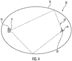
- Figures 2 and 3 depict an exemplary apparatus for curing a coated glass fiber.
- the apparatus includes a cavity segment 20.
- the cavity segment 20 defines a substantially cylindrical cavity 25 having an elliptical shape and a reflective inner surface.
- the cavity 25 defines a first line focus 21 and a second line focus 22.
- One or more UVLED sources 24 are positioned along the first line focus 21.
- the cavity segment 20 may include a plurality of UVLED sources 24 positioned contiguously to one another along the first line focus 21 (i.e., directly stacked). In another embodiment, adjacent UVLED sources may be vertically separated by a space of at least about 5 millimeters ( e . g ., at least about 10 millimeters).
- the second line focus 22 further defines a curing axis along which a coated glass fiber 26 passes so it can be cured. As depicted in Figure 4 , UV rays 23 emitted from the UVLED source 24 may reflect off the inner surface of the cavity 25 such that the reflected UV rays 23 are incident to the coated glass fiber 26.
- the cavity segment 20 typically includes a single UVLED source positioned within a particular horizontal plane.
- multiple UVLEDs may be positioned ( e . g ., at a point other than the first focal line) within a horizontal plane to promote more uniform curing of the glass fiber.
- an apparatus for curing a coated glass fiber may include a plurality of differently oriented cavity segments. Each cavity may have a common curing axis ( e . g ., the second focal line), but a different first line focus.
- a second cavity segment 30 for curing a glass fiber may have a different orientation than the first cavity segment 20 (e.g., the second cavity segment 30 may have UVLED sources positioned along a line focus 31 that differs from the first line focus 21).
- the second cavity segment 30 is rotated 180 degrees relative to the orientation of the first cavity segment 20. That said, various degrees of rotation may separate adjacent cavity segments. By way of non-limiting illustration, a 45-degree rotation, a 90-degree rotation, or a 135-degree rotation may separate adjacent cavity segments while maintaining the common curing axis.
- the positioning of a plurality of cavity segments in a three-dimensional arrangement may be defined by the cylindrical coordinate system ( i . e ., r , ⁇ , z).
- the curing axis defines a z-axis.
- the variable r is the perpendicular distance of a point to the z-axis.
- the variable ⁇ describes the angle in a plane that is perpendicular to the z-axis.
- the variable ⁇ describes the angle between a reference axis (e.g., the x-axis) and the orthogonal projection of a point onto the x-y plane.
- the z variable describes the height or position of a reference point along the z-axis.
- a plurality of cavity segments having the same elliptical dimensions may be positioned in a helical arrangement with the first cavity segment at the position (1, 0, 0), where r is fixed at a constant distance (i.e., represented here as a unitless 1). Additional cavity segments may be positioned, for example, every 90 degrees (i.e., ⁇ /2) with a ⁇ z of 1 ( i . e ., a positional step change represented here as a unitless 1).
- a second cavity segment would have the coordinates (1, ⁇ /2, 1)
- a third cavity segment would have the coordinates (1, ⁇ , 2)
- a fourth cavity segment would have the coordinates (1, 3 ⁇ /2, 3), thereby defining a helical configuration.
- the respective cavity segments are rotated around the curing axis.
- the respective distances r and z need not be equivalent.
- the several cavity segments in an arrangement as herein disclosed need not be offset by 90 degrees ( e . g ., ⁇ /2, ⁇ , 3 ⁇ /2, etc.).
- the respective cavity segments may be offset by 60 degrees ( e . g ., ⁇ /3, 2 ⁇ /3, ⁇ , etc.) or by 120 degrees ( e . g ., 2 ⁇ /3, 4 ⁇ /3, 2 ⁇ , etc.).
- the cavity segments in an arrangement as discussed herein need not follow a regularized helical rotation.
- the protective tube interferes with the UV radiation directed toward the curing axis.
- Applicant simulated directing a 0.1-millimeter wide UVLED having an emission pattern of cos 1.5 ( ⁇ ) directly toward (i.e., employing an emission angle of 0 degrees) a target having a diameter of 250 microns, the approximate diameter of a representative optical fiber.
- the size of a UVLED refers to its actual size or, if the UVLED is rescaled with a lens, its effective size.
- the simulation positioned the point source and the target at opposite foci within a reflective elliptic cylinder having a major axis length of 54 millimeters and a minor axis length of 45.8 millimeters. In the absence of a protective tube, nearly 100 percent of the UV rays hit the target.
- UV rays having an incidence angle other than approximately 90 degrees with the protective tube can be undesirably refracted or reflected.
- Applicant also simulated directing the UVLED toward a 250-micron target surrounded by a protective tube while employing an emission angle of 90 degrees rather than 0 degrees.
- Table 1 shows UVLED efficiency (i.e ., the percent of UV radiation hitting a 250-micron target) at respective emission angles of 0 degrees and 90 degrees for UVLEDs of various widths.
- Table 1 (UVLED Efficiency) UVLED Width (mm) UVLED Efficiency (0° emission angle) UVLED Efficiency (90° emission angle) 0.1 77 100 0.2 77 79 0.3 77 61 0.4 77 50 0.5 76 43 1 45 25 1.5 31 17 2 24 13 2.5 19 11
- Table 2 shows UVLED efficiency for a UVLED having a width (or effective width) of 0.1 mm.
- Table 2 UVLED Efficiency
- Elliptic Cylinder Major Axis Width mm
- Elliptic Cylinder Minor Axis Width mm
- Protective Tube Diameter mm
- Emission Pattern Emission Angle degrees
- UVLED Efficiency percentage
- Applicant further simulated UVLED efficiency for various emission angles using various UVLEDs, where ( i ) the reflective elliptic cylinder had a major axis length of 54 millimeters and a minor axis length of 45.8 millimeters, ( ii ) the protective tube had a diameter of 24 millimeters, and ( iii ) the UVLED had an emission pattern of cos 1.5 ( ⁇ ).
- Figure 5 graphically depicts the relationship between UVLED emission angle and UVLED efficiency for UVLEDs of various widths. In brief, Figure 5 shows that for a UVLED having a width of less than 0.5 millimeter, employing an emission angle of more than 0 degrees improves UVLED efficiency.
- UVLED efficiency 1001.3 x 3 + 1166.1 x 2 ⁇ 461.6 x + 140.45, where x is the width of the UVLED, where x is the width of the UVLED, x ⁇ 0.5 millimeter, and the UVLED has an emission pattern of cos 1.5 ( ⁇ ).
- the optimum emission angle is typically at least about 30 degrees, such as between 30 degrees and 100 degrees (e.g., about 90 degrees for a UVLED having a width of about 0.3 millimeter or less), more typically between about 30 degrees and 60 degrees (e.g., about 45 degrees for a UVLED having a width of about 0.22 millimeter), between each UVLED source and the major axis of the elliptical cylinder.
- ever smaller UVLEDs may facilitate the deployment of a curing apparatus that can efficiently employ emission angles approaching 180 degrees.
- such a curing apparatus might employ emission angles greater than about 100 degrees, such as between about 120 degrees and 150 degrees (e.g., about 135 degrees).
- a protective tube is present within the elliptical cylinder (i.e., surrounding the curing axis)
- employing an angled UVLED source in this way will provide improved UV absorption during curing.
- Figure 6 depicts an exemplary apparatus 50 for curing a coated glass-fiber 26 in accordance with the present invention.
- the apparatus 50 employs one or more angled UVLED sources 24 positioned within a substantially cylindrical cavity 25 having an elliptical shape and having a reflective inner surface.
- the cavity 25 defines a first line focus 21 and a second line focus 22.
- the second line focus 22 defines a curing axis.
- a coated glass fiber 26 passes along the curing axis during curing.
- a protective tube 35 surrounds the curing axis and the coated glass fiber 26.
- the cavity 25 also defines a major axis 34 that intersects the first line focus 21 and the second line focus 22.
- One or more UVLED sources 24 are positioned along the first line focus 21.
- Each UVLED source 24 emits UV rays 23 in a distinctive emission pattern.
- an emission pattern has a line of average emission L avg 23a (i.e., an average of all the UV rays emitted by the UVLED source 24).
- an UVLED source 24 is angled away from the coated glass fiber 26.
- the UVLED source 24 is positioned so that an emission angle ⁇ is defined between the line of average emission L avg 23a and the elliptical cylinder's major axis 34.
- the emission angle ⁇ is typically between about 30 degrees and 100 degrees (e.g., between 30 degrees and 60 degrees), more typically between about 40 degrees and 50 degrees (e.g., 45 degrees).
- the emission angle ⁇ is typically calculated relative to the line of average emission L avg for a UVLED source (e.g., a single UVLED), it is within the scope of the invention to describe the emission angle ⁇ relative to a line defined by a UVLED source's median or mode (i.e., a line of maximum emission L max ).
- UV radiation emitted from a UVLED is not emitted from a single point. Therefore, and because of the small size of a coated glass fiber (e.g ., a 250-micron diameter), it is desirable to use small UVLED sources (e.g ., a 3-millimeter square UVLED or a 1-millimeter square UVLED). In general, a greater percentage of reflected UV radiation will be incident to the coated glass fiber using a small UVLED as compared to using a larger UVLED.
- small UVLED sources e.g a 3-millimeter square UVLED or a 1-millimeter square UVLED
- each UVLED source may include a lens (e.g ., a convex lens, such as a biconvex or plano-convex lens) for focusing emitted UV radiation.
- each lens may have a focus at one of the two line foci (e.g ., the line focus not defining a curing axis).
- a cylindrical lens with a high numerical aperture can be used to rescale a 3-millimeter square UVLED, so that it has an effective width of about 0.4 millimeter or less at the line focus.
- the apparatus for curing a coated glass fiber may employ one or more optical fibers (e.g., one or more multimode optical fibers) to transmit UV radiation.
- these optical fibers are typically positioned along the first line focus of the apparatus as an alternative to positioning UVLED sources along the first line focus.
- each optical fiber is coupled to one or more sources of UV radiation, such as a UVLED source.
- a plurality of small UVLEDS may be coupled to a plurality of optical fibers in a one-to-one relationship ( e.g ., 20 UVLEDS and 20 optical fibers).
- the optical fibers may be arranged in various configurations at or near the first line focus.
- At least one - and typically each - optical fiber is oriented at the first line focus to provide an emission angle of between about 30 degrees and 120 degrees ( e.g ., between 45 degrees and 90 degrees).
- Such optical fibers typically employ a central glass fiber, but may alternatively employ a central plastic fiber.
- an optical fiber to transmit UV radiation into the cavity may facilitate the deployment of a curing apparatus that can efficiently employ emission angles approaching 180 degrees.
- a curing apparatus might employ emission angles between 120 degrees and 180 degrees ( e.g ., about 150 degrees).
- multimode optical fibers are typically employed for purposes of UV-radiation transmission. That said, it is within the scope of the present invention to employ single-mode optical fibers (e.g ., holey glass fibers).
- An exemplary single-mode optical fiber is a large-mode-area fiber (LMA) that provides a Gaussian beam having a diameter of 0.1 millimeter or less.
- An exemplary holey optical fiber is disclosed in commonly assigned U.S. Patent Application No. 2. US 2010/0189397 for a Single-Mode Optical Fiber , filed January 22, 2010, (Richard et al. ).
- UVLEDs are capable of emitting wavelengths within a much smaller spectrum than conventional UV lamps. This promotes the use of more of the emitted electromagnetic radiation for curing. That said, the UVLED apparatus (and its related system and method) disclosed herein may be modified to employ mercury lamps and/or fusion lamps as radiation sources ( e . g ., a supplemental source of UV radiation if insufficient curing is achieved using only UVLEDs).
- a UVLED source for use in the present invention may be any suitable UVLED that emits electromagnetic radiation having wavelengths of between about 200 nanometers and 600 nanometers.
- the UVLED may emit electromagnetic radiation having wavelengths of between about 200 nanometers and 450 nanometers ( e.g ., between about 250 nanometers and 400 nanometers).
- the UVLED may emit electromagnetic radiation having wavelengths of between about 300 nanometers and 400 nanometers.
- the UVLED may emit electromagnetic radiation having wavelengths of between about 350 nanometers and 425 nanometers.
- a UVLED typically emits a narrow band of electromagnetic radiation.
- the UVLED may substantially emit electromagnetic radiation having wavelengths that vary by no more than about 30 nanometers, typically no more than about 20 nanometers (e.g., a UVLED emitting a narrow band of UV radiation mostly between about 375 nanometers and 395 nanometers). It has been observed that a UVLED emitting a narrow band of UV radiation mostly between about 395 nanometers and 415 nanometers is more efficient than other narrow bands of UV radiation.
- the UVLED apparatus may employ UVLED sources that have a mean output wavelength at least about 10 nanometers greater than the glass-fiber coating's targeted absorption peak (e.g., at least about 10 to 15 nanometers greater than a targeted absorption peak). That said, it is within the scope of the present invention to employ UVLEDs that have a mean output wavelength within about 10 nanometers (e.g., within about 5 nanometers) of a targeted absorption peak.
- an exemplary UVLED source emits substantially all of its electromagnetic radiation within a defined range (e.g ., between 350 nanometers and 450 nanometers, such as between 370 nanometers and 400 nanometers), the UVLED source may emit small amounts of electromagnetic radiation outside the defined range.
- 80 percent or more (e.g ., at least about 90 percent) of the output ( i.e ., emitted electromagnetic radiation) of an exemplary UVLED source is typically within a defined range (e.g ., between about 375 nanometers and 425 nanometers).
- UVLEDs can have various emission patterns (e.g. , far field pattern).
- a UVLED employed in accordance with the present invention may have a substantially Lambertian emission pattern.
- a UVLED source e.g ., a UVLED
- a UVLED may have a Gaussian or multimodal emission pattern.
- Another exemplary UVLED may have an emission pattern of cos 1.5 ( ⁇ ) or cos 2 ( ⁇ ).
- UVLEDs are typically much smaller than conventional UV lamps (e.g., mercury bulbs).
- the UVLED may be a 0.25-inch square UVLED.
- the UVLED may be affixed to a platform (e.g., a 1-inch square or larger mounting plate).
- a platform e.g., a 1-inch square or larger mounting plate.
- other UVLED shapes and sizes are within the scope of the present invention.
- a 3-millimeter square UVLED may be employed in the apparatus according to the present invention.
- Each UVLED may have a power output of as much as 32 watts (e.g., a UVLED having a power input of about 160 watts and a power output of about 32 watts). That said, UVLEDs having outputs greater than 32 watts ( e.g ., 64 watts) may be employed as such technology becomes available. Using UVLEDs with higher power output may be useful for increasing the rate at which optical-fiber coatings cure, thus promoting increased production line speeds.
- 32 watts e.g., a UVLED having a power input of about 160 watts and a power output of about 32 watts. That said, UVLEDs having outputs greater than 32 watts (e.g ., 64 watts) may be employed as such technology becomes available. Using UVLEDs with higher power output may be useful for increasing the rate at which optical-fiber coatings cure, thus promoting increased production line speeds.
- Each UVLED source may be positioned at a distance of between about 1 millimeter and 100 millimeters ( e.g ., typically between about 5 millimeters and 30 millimeters) from the optical fiber to be cured ( e.g ., from the curing axis). More typically, each UVLED source is positioned at a distance of about 25 millimeters from the optical fiber to be cured.
- UVLEDs may absorb incident electromagnetic radiation, which might diminish the quantity of reflected UV radiation available for absorption by the glass-fiber coating. Moreover, incident UV radiation can damage a UVLED. Therefore, in an apparatus for curing glass-fiber coatings having a plurality of UVLEDs, it may be desirable to position the UVLEDs in a way that reduces UV radiation incident to the UVLEDs. Accordingly, a vertical space of at least about 10 millimeters may separate adjacent UVLEDs. Moreover, the UVLEDs may employ a reflective surface (e.g., a surface coating) that promotes reflection of incident electromagnetic radiation yet permits the transmission of emitted electromagnetic radiation.
- a reflective surface e.g., a surface coating
- glass fiber is typically rotated or otherwise subjected to perturbations during drawing operations to reduce unwanted dispersion effects. It is thought that this may further enhance the curing process as herein described.
- the foregoing description embraces the curing of one or more coating layers on a glass fiber.
- the disclosed apparatus, system, and method may be similarly employed to cure a buffer layer onto an optical fiber or a ribbon matrix around a plurality of optical fibers.
- the resulting optical fiber includes one or more coating layers (e.g ., a primary coating and a secondary coating). At least one of the coating layers - typically the secondary coating - may be colored and/or possess other markings to help identify individual fibers. Alternatively, a tertiary ink layer may surround the primary and secondary coatings.
- the resulting optical fiber may have one or more coatings (e.g ., the primary coating) that comprise a UV-curable, urethane acrylate composition.
- the primary coating may include between about 40 and 80 weight percent of polyether-urethane acrylate oligomer as well as photoinitiator, such as LUCIRIN® TPO, which is commercially available from BASF.
- the primary coating typically includes one or more oligomers and one or more monomer diluents (e.g., isobornyl acrylate), which may be included, for instance, to reduce viscosity and thereby promote processing.
- compositions for the primary coating include UV-curable urethane acrylate products provided by DSM Desotech (Elgin, Illinois) under various trade names, such as DeSolite® DP 1011, DeSolite® DP 1014, DeSolite® DP 1014XS, and DeSolite® DP 1016.
- An exemplary coating system is available from Draka Comteq under the trade name COLORLOCK® XS .
- Each coating layer is typically cured before a subsequent coating layer is applied.
- a coated glass fiber may pass through a first curing apparatus after a primary coating is applied. Once the primary coating has cured, a secondary coating may be applied and cured using a second curing apparatus. Alternatively, both the primary and secondary coatings may be applied, after which the primary and secondary coatings are cured concurrently.
- an optical fiber with a primary coating typically has an outer diameter of between about 235 microns and about 265 microns ( ⁇ m).
- the component glass fiber itself i.e ., the glass core and surrounding cladding layers
- the component glass fiber may have an outer diameter of about 125 microns.
- the primary coating may have an outer diameter of between about 175 microns and about 195 microns (i.e ., a primary coating thickness of between about 25 microns and 35 microns)
- the secondary coating may have an outer diameter of between about 235 microns and about 265 microns ( i.e ., a secondary coating thickness of between about 20 microns and 45 microns).
- the optical fiber may include an outermost ink layer, which is typically between two and ten microns thick.
- the resulting optical fiber may possess a reduced diameter (e.g., an outermost diameter between about 150 microns and 230 microns).
- the thickness of the primary coating and/or secondary coating is reduced, while the diameter of the component glass fiber is maintained at about 125 microns.
- the primary coating layer may have an outer diameter of between about 135 microns and about 175 microns ( e.g ., about 160 microns)
- the secondary coating layer may have an outer diameter of between about 150 microns and about 230 microns ( e.g ., more than about 165 microns, such as 190-210 microns or so).
- the total diameter of the optical fiber is reduced to less than about 230 microns ( e.g. , about 200 microns).
- Exemplary coating formulations for use with the apparatus and method described herein are disclosed in the following applications of the same applicant: U.S. Patent Application No. 61/112,595 for a Microbend-Resistant Optical Fiber , filed November 7, 2008, (Overton); International Patent Application Publication No. WO 2009/062131 A1 for a Microbend-Resistant Optical Fiber , (Overton); U.S. Patent Application Publication No. US2009/0175583 A1 for a Microbend-Resistant Optical Fiber , (Overton); and U.S. Patent Application No. US 2010/0119202 for a Reduced-Diameter Optical Fiber , filed November 6, 2009, (Overton).
Claims (7)
- Verfahren zum Härten einer Beschichtung auf einer Glasfaser, umfassend:Leiten einer Glasfaser mit einer unvollständig gehärteten Beschichtung bei einer Liniengeschwindigkeit vf durch einen Hohlraum und entlang einer Härtungsachse, die durch den Hohlraum definiert ist;Emittieren von UV Strahlung aus einer ersten UVLED Anordnung in den Hohlraum, um das Härten der Beschichtung zu fördern, wobei die erste UVLED Anordnung eine Mehrzahl von UVLED Quellen umfasst, von denen jede einen oszillierenden Ausgang xn(t) einer UV Strahlung mit einer maximalen Ausgangsintensität xn(t)max und einer minimalen Ausgangsintensität xn(t)min emittiert;wobei die erste UVLED Anordnung eine normierte Summe xtotal(t, vf) definiert:
 k = Anzahl an UVLED Quellen in der ersten UVLED Anordnung,dn = Entfernung entlang der Härtungsachse von einer ersten UVLED Quelle zu einer n-ten UVLED Quelle;
undwobei, bei einer vorgegebenen Liniengeschwindigkeit, xtotal(t, vf) durch Abstimmen der Phase, der Periodendauer und/oder des Tastgrads der entsprechenden UVLED Quellenausgänge einen im Wesentlichen konstanten Wert aufweist. - Verfahren nach Anspruch 1, wobei die maximale Ausgangsintensität xn(t)max jeder UVLED Quelle in der ersten UVLED Anordnung im Wesentlichen gleich ist.
- Verfahren nach einem der Ansprüche 1 bis 2, umfassend den Schritt des Anpassens der Phase des Ausgangs wenigstens einer UVLED Quelle in Reaktion auf eine Änderung der Liniengeschwindigkeit vf der Glasfaser, sodass xtotal(t, vf) einen im Wesentlichen konstanten Wert für eine gegebene Liniengeschwindigkeit aufweist.
- Verfahren nach einem der Ansprüche 1 bis 3, umfassend den Schritt des Erhöhens der Ausgangsintensität der UVLED Quellen in Reaktion auf einen Anstieg der Liniengeschwindigkeit vf der Glasfaser.
- Verfahren nach einem der Ansprüche 1 bis 4, umfassend den Schritt des Verringerns der Ausgangsintensität der UVLED Quellen in Reaktion auf eine Verringerung der Liniengeschwindigkeit vf der Glasfaser.
- Verfahren nach einem der Ansprüche 1 bis 5, umfassend den Schritt des Betreibens einer UVLED Quelle in der ersten UVLED Anordnung bei einer Stromstärke, die größer ist als die maximale Nennstromstärke der UVLED Quelle, wobei die UVLED Quelle eine größere maximale Ausgangsintensität xn(t)max aufweist, als erreicht werden könnte, wenn die UVLED Quelle bei ihrer maximalen Nennstromstärke betrieben würde.
- Verfahren nach einem der Ansprüche 1 bis 6, umfassend:Betreiben einer Mehrzahl von UVLED Quellen, die eine zweite UVLED Anordnung definieren, wobei jede UVLED Quelle in der zweiten UVLED Anordnung bei einer Stromstärke betrieben wird, die größer als ihre maximale Nennstromstärke ist, wobei jede UVLED Quelle in der zweiten UVLED Anordnung einen oszillierenden Ausgang yn(t) einer UV Strahlung mit einer maximalen Ausgangsintensität yn(t)max und einer minimalen Ausgangsintensität yn(t)min aufweist, wobei die maximale Ausgangsintensität yn(t)max jeder UVLED Quelle größer ist, als erreicht werden könnte, wenn jede der UVLED Quellen bei ihrer maximalen Nennstromstärke betrieben würde, und wobei die maximale Ausgangsintensität yn(t)max wenigstens einer UVLED Quelle in der zweiten UVLED Anordnung von der maximalen Ausgangsintensität xn(t)max wenigstens einer UVLED Quelle in der ersten UVLED Anordnung verschieden ist; undAusrichten von UV Strahlung aus der zweiten UVLED Anordnung, um das Härten der Beschichtung zu fördern.
Applications Claiming Priority (1)
| Application Number | Priority Date | Filing Date | Title |
|---|---|---|---|
| US37231210P | 2010-08-10 | 2010-08-10 |
Publications (3)
| Publication Number | Publication Date |
|---|---|
| EP2418183A2 EP2418183A2 (de) | 2012-02-15 |
| EP2418183A3 EP2418183A3 (de) | 2016-10-05 |
| EP2418183B1 true EP2418183B1 (de) | 2018-07-25 |
Family
ID=44677456
Family Applications (1)
| Application Number | Title | Priority Date | Filing Date |
|---|---|---|---|
| EP11176947.7A Active EP2418183B1 (de) | 2010-08-10 | 2011-08-09 | Verfahren zur Härtung beschichteter Glasfasern mit erhöhter UVLED-Intensität |
Country Status (4)
| Country | Link |
|---|---|
| US (2) | US20120040105A1 (de) |
| EP (1) | EP2418183B1 (de) |
| CN (1) | CN102408198B (de) |
| DK (1) | DK2418183T3 (de) |
Families Citing this family (32)
| Publication number | Priority date | Publication date | Assignee | Title |
|---|---|---|---|---|
| WO2010077132A1 (en) | 2008-12-31 | 2010-07-08 | Draka Comteq B.V. | Uvled apparatus for curing glass-fiber coatings |
| US9014525B2 (en) | 2009-09-09 | 2015-04-21 | Draka Comteq, B.V. | Trench-assisted multimode optical fiber |
| DK2388239T3 (da) | 2010-05-20 | 2017-04-24 | Draka Comteq Bv | Hærdningsapparat, der anvender vinklede UV-LED'er |
| US8871311B2 (en) | 2010-06-03 | 2014-10-28 | Draka Comteq, B.V. | Curing method employing UV sources that emit differing ranges of UV radiation |
| EP2418183B1 (de) | 2010-08-10 | 2018-07-25 | Draka Comteq B.V. | Verfahren zur Härtung beschichteter Glasfasern mit erhöhter UVLED-Intensität |
| US8571369B2 (en) | 2010-09-03 | 2013-10-29 | Draka Comteq B.V. | Optical-fiber module having improved accessibility |
| FR2966256B1 (fr) | 2010-10-18 | 2012-11-16 | Draka Comteq France | Fibre optique multimode insensible aux pertes par |
| US8824845B1 (en) | 2010-12-03 | 2014-09-02 | Draka Comteq, B.V. | Buffer tubes having reduced stress whitening |
| FR2971061B1 (fr) | 2011-01-31 | 2013-02-08 | Draka Comteq France | Fibre optique a large bande passante et a faibles pertes par courbure |
| EP2482106B1 (de) | 2011-01-31 | 2014-06-04 | Draka Comteq B.V. | Multimodusfaser |
| WO2012161775A1 (en) | 2011-02-21 | 2012-11-29 | Draka Comteq B.V. | Optical-fiber interconnect cable |
| EP2495589A1 (de) | 2011-03-04 | 2012-09-05 | Draka Comteq B.V. | Seltene-Erden dotierte Verstärkungsglasfaser für kompakte Vorrichtungen und Herstellungsverfahren dafür |
| EP2503368A1 (de) | 2011-03-24 | 2012-09-26 | Draka Comteq B.V. | Multimodus-Glasfaser mit verbesserter Biegefestigkeit |
| EP2506044A1 (de) | 2011-03-29 | 2012-10-03 | Draka Comteq B.V. | Multimodus-Glasfaser |
| EP2518546B1 (de) | 2011-04-27 | 2018-06-20 | Draka Comteq B.V. | Strahlungsgresistente multimodale optische Faser mit hoher Bandbreite |
| EP2527893B1 (de) | 2011-05-27 | 2013-09-04 | Draka Comteq BV | Singlemode-Glasfaser |
| ES2451369T3 (es) | 2011-06-09 | 2014-03-26 | Draka Comteq Bv | Fibra óptica de modo único |
| EP2541292B1 (de) | 2011-07-01 | 2014-10-01 | Draka Comteq BV | Multimode-Lichtleitfaser |
| EP2766762B1 (de) * | 2011-10-12 | 2019-07-17 | Phoseon Technology, Inc. | Mehrere lichtsammlungs- und linsenkombinationen mit benachbarten foki zur härtung von optischen fasern |
| EP2584340A1 (de) | 2011-10-20 | 2013-04-24 | Draka Comteq BV | Wasserstoffmessfaser und Wasserstoffsensor |
| NL2007831C2 (en) | 2011-11-21 | 2013-05-23 | Draka Comteq Bv | Apparatus and method for carrying out a pcvd deposition process. |
| US8929701B2 (en) | 2012-02-15 | 2015-01-06 | Draka Comteq, B.V. | Loose-tube optical-fiber cable |
| US9277623B2 (en) | 2012-03-29 | 2016-03-01 | Phoseon Technology, Inc. | Load current control circuit |
| WO2013160714A1 (en) | 2012-04-27 | 2013-10-31 | Draka Comteq Bv | Hybrid single and multimode optical fiber for a home network |
| US9188754B1 (en) | 2013-03-15 | 2015-11-17 | Draka Comteq, B.V. | Method for manufacturing an optical-fiber buffer tube |
| US9442008B2 (en) | 2013-05-06 | 2016-09-13 | Phoseon Technology, Inc. | Method and system for determining curing tube clarity |
| CN106458736B (zh) * | 2014-06-27 | 2022-01-11 | 古河电气工业株式会社 | 光纤的制造方法和光纤的制造装置 |
| SE1550842A1 (sv) * | 2015-06-17 | 2016-09-27 | Inventech Europe Ab | Device and method for controlling the fixation of an in-line thread treatment |
| CN105060739B (zh) * | 2015-07-31 | 2018-06-12 | 长飞光纤光缆股份有限公司 | 一种光强可调的光纤涂层紫外固化设备 |
| DE102016100144A1 (de) | 2016-01-05 | 2017-07-06 | J-Fiber Gmbh | Vorrichtung zum Beschichten einer Faser sowie Verfahren zum Beschichten einer Faser und Faser |
| US10486194B2 (en) * | 2017-12-11 | 2019-11-26 | Ofs Fitel, Llc | Post-draw tower optical fiber coating curing |
| DE102020126040A1 (de) | 2020-10-05 | 2022-04-07 | Samir Lamrini | Aushärtevorrichtung für Beschichtungen von Glasfasern |
Family Cites Families (337)
| Publication number | Priority date | Publication date | Assignee | Title |
|---|---|---|---|---|
| JPS5228909B2 (de) | 1971-09-04 | 1977-07-29 | ||
| US3737051A (en) | 1972-01-07 | 1973-06-05 | Tokyo Shibaura Electric Co | Apparatus for aligning edges of stacked sheets in the vertical direction |
| US3784836A (en) | 1972-10-06 | 1974-01-08 | Sybron Corp | Ir generator having ellipsoidal and paraboloidal reflectors |
| US3819929A (en) | 1973-06-08 | 1974-06-25 | Canrad Precision Ind Inc | Ultraviolet lamp housing |
| US4033263A (en) | 1974-12-12 | 1977-07-05 | Harris Corporation | Wide range power control for electric discharge lamp and press using the same |
| JPS5173434A (en) | 1974-12-23 | 1976-06-25 | Canon Kk | Rokosochi |
| US3983039A (en) | 1975-03-03 | 1976-09-28 | Fusion Systems Corporation | Non-symmetrical reflector for ultraviolet curing |
| US4037112A (en) | 1975-03-25 | 1977-07-19 | Ppg Industries, Inc. | Apparatus for crosslinking ultraviolet light curable coatings |
| US4010374A (en) | 1975-06-02 | 1977-03-01 | Ppg Industries, Inc. | Ultraviolet light processor and method of exposing surfaces to ultraviolet light |
| JPS5598706A (en) | 1979-01-23 | 1980-07-28 | Nippon Telegr & Teleph Corp <Ntt> | Glass fiber for optical transmission and its production |
| DE2911410A1 (de) | 1979-03-23 | 1980-09-25 | Aeg Telefunken Kabelwerke | Vorrichtung zur kontrolle der daempfung von lichtleitfasern waehrend ihrer umhuellung |
| US4309452A (en) | 1980-10-01 | 1982-01-05 | Gaf Corporation | Dual gloss coating and process therefor |
| US4321073A (en) | 1980-10-15 | 1982-03-23 | Hughes Aircraft Company | Method and apparatus for forming metal coating on glass fiber |
| US4518628A (en) | 1982-05-28 | 1985-05-21 | International Telephone And Telegraph Corporation | Hermetic coating by heterogeneous nucleation thermochemical deposition |
| US4479984A (en) | 1982-12-27 | 1984-10-30 | At&T Bell Laboratories | Radiation curable multifilament composite |
| US4490410A (en) | 1983-05-20 | 1984-12-25 | Showa Highpolymer Co., Ltd. | Method of affixing a decorative pattern to a stock or a molded component |
| JPS60126830A (ja) | 1983-12-14 | 1985-07-06 | Nippon Jido Seigyo Kk | パタ−ンの欠陥検査装置に用いる走査方法 |
| JPS60184250A (ja) | 1984-03-01 | 1985-09-19 | フュージョン・システムズ・コーポレーション | セグメント化された反射器を有するランプ |
| JPS60191038A (ja) | 1984-03-07 | 1985-09-28 | Oak Seisakusho:Kk | 紫外線照射装置 |
| JPS6110440A (ja) | 1984-06-26 | 1986-01-17 | Yokohama Rubber Co Ltd:The | 紫外線硬化frpの連続製造方法およびその装置 |
| GB2166975B (en) | 1984-11-16 | 1988-06-02 | Stc Plc | Optical fibres |
| JPS6226876A (ja) | 1985-07-29 | 1987-02-04 | Oki Electric Ind Co Ltd | 発光ダイオ−ドアレイの整列方法 |
| NL8502534A (nl) | 1985-09-17 | 1987-04-16 | Philips Nv | Bestralingsapparaat. |
| US4910107A (en) | 1985-12-16 | 1990-03-20 | Canon Kabushiki Kaisha | Optical recording-reproducing method and device by using the same |
| US4636405A (en) | 1985-12-24 | 1987-01-13 | Corning Glass Works | Curing apparatus for coated fiber |
| US4710638A (en) | 1986-02-10 | 1987-12-01 | Fusion Systems Corporation | Apparatus for treating coatings |
| NL8601197A (nl) | 1986-05-13 | 1987-12-01 | Philips Nv | Bestralingsinrichting, inrichting en werkwijze voor het bekleden van een draadvormig lichaam. |
| US4761168A (en) | 1986-09-22 | 1988-08-02 | American Telephone And Telegraph Company, At&T Bell Laboratories | Optical fiber manufacturing technique |
| FR2607801B1 (fr) | 1986-12-04 | 1989-03-03 | Saint Gobain Vetrotex | Procede et dispositif de fabrication d'un fil de verre simple obtenu directement sous filiere |
| JPS63182528A (ja) | 1987-01-26 | 1988-07-27 | Sumitomo Electric Ind Ltd | 光フアイバ線引装置用紫外線照射器の紫外線照度測定器 |
| JP2566992B2 (ja) | 1987-10-22 | 1996-12-25 | 株式会社フジクラ | 光ファイバテープ心線の製造方法 |
| CA1337056C (en) * | 1987-10-30 | 1995-09-19 | Bob J. Overton | Methods of and apparatus for curing optical fiber coatings |
| US4913859A (en) | 1987-10-30 | 1990-04-03 | At&T Bell Laboratories | Methods of curing optical fiber coatings |
| JPH01124324A (ja) | 1987-11-10 | 1989-05-17 | Watanabeyasushi Kk | 育苗用照明装置 |
| JPH07113104B2 (ja) | 1987-11-13 | 1995-12-06 | 日本合成ゴム株式会社 | 光フアイバー用硬化性バンドリング材 |
| US4838643A (en) | 1988-03-23 | 1989-06-13 | Alcatel Na, Inc. | Single mode bend insensitive fiber for use in fiber optic guidance applications |
| JP2585711B2 (ja) | 1988-05-18 | 1997-02-26 | 株式会社日立製作所 | 感熱転写記録装置 |
| US5440660A (en) | 1988-05-23 | 1995-08-08 | The United States Of America As Represented By The Secretary Of Navy | Fiber optic microcable produced with fiber reinforced ultraviolet light cured resin and method for manufacturing same |
| FR2637150B1 (fr) | 1988-09-23 | 1995-07-28 | Neiman Sa | Reseau de diodes electroluminescentes |
| CA1321671C (en) | 1989-05-11 | 1993-08-24 | Paul J. Shustack | Ultraviolet radiation-curable coatings for optical fibers and optical fibers coated therewith |
| US4962992A (en) | 1989-05-15 | 1990-10-16 | At&T Bell Laboratories | Optical transmission media and methods of making same |
| US4980701A (en) | 1989-07-03 | 1990-12-25 | Eastman Kodak Company | Non-impact printhead using a mask with a dye sensitive to and adjusted by light in a first spectrum to balance the transmission of light in a second spectrum emitted by an LED array |
| CA2034162A1 (en) | 1990-02-23 | 1991-08-24 | Akira Inoue | Method and apparatus for measuring the thickness of a coating |
| US5219623A (en) | 1990-03-09 | 1993-06-15 | At&T Bell Laboratories | Methods of producing an article which includes a light energy cured coating material |
| US5427862A (en) | 1990-05-08 | 1995-06-27 | Amoco Corporation | Photocurable polyimide coated glass fiber |
| DE4022234A1 (de) | 1990-07-12 | 1992-01-16 | Herberts Gmbh | Verfahren zur herstellung von schutz-, hilfs- und isoliermaterialien auf faserbasis, fuer elektrische zwecke und optische leiter unter verwendung von durch energiereiche strahlung haertbaren impraegniermassen |
| JPH04133646A (ja) | 1990-09-20 | 1992-05-07 | Secoh Giken Inc | 3相リラクタンス型電動機 |
| JP2635475B2 (ja) | 1992-02-03 | 1997-07-30 | 株式会社フジクラ | 光ファイバの被覆形成方法 |
| JPH05323462A (ja) | 1992-05-18 | 1993-12-07 | Konica Corp | 写真焼付装置のミラートンネル |
| DE4226344C2 (de) | 1992-08-08 | 2002-07-18 | Alcatel Sa | Verfahren und Vorrichtung zur Herstellung einer optischen Faser |
| US5278432A (en) | 1992-08-27 | 1994-01-11 | Quantam Devices, Inc. | Apparatus for providing radiant energy |
| US5418369A (en) | 1993-03-12 | 1995-05-23 | At&T Corp. | System for continuously monitoring curing energy levels within a curing unit |
| US5366527A (en) | 1993-04-05 | 1994-11-22 | Corning Incorporated | Method and apparatus for coating optical waveguide fibers |
| US5420768A (en) | 1993-09-13 | 1995-05-30 | Kennedy; John | Portable led photocuring device |
| US5535673A (en) | 1993-11-03 | 1996-07-16 | Corning Incorporated | Method of printing a color filter |
| KR960706405A (ko) | 1993-12-17 | 1996-12-09 | 테릴 켄트 퀼리 | 근접 석판인쇄에 의한 융식성 결상법(ablative imaging by proximity lithography) |
| US5762867A (en) | 1994-09-01 | 1998-06-09 | Baxter International Inc. | Apparatus and method for activating photoactive agents |
| US5440137A (en) | 1994-09-06 | 1995-08-08 | Fusion Systems Corporation | Screw mechanism for radiation-curing lamp having an adjustable irradiation area |
| FR2725797B1 (fr) | 1994-10-13 | 1997-01-03 | Alcatel Cable | Procede de revetement d'un ruban de fibres optiques au moyen d'une resine, et dispositif pour la mise en oeuvre d'un tel procede |
| JPH08174567A (ja) | 1994-10-25 | 1996-07-09 | Ushio Inc | 光照射器 |
| US5660461A (en) | 1994-12-08 | 1997-08-26 | Quantum Devices, Inc. | Arrays of optoelectronic devices and method of making same |
| US5574816A (en) | 1995-01-24 | 1996-11-12 | Alcatel Na Cable Sytems, Inc. | Polypropylene-polyethylene copolymer buffer tubes for optical fiber cables and method for making the same |
| DE69614023T2 (de) | 1995-04-20 | 2002-03-21 | At & T Corp | Verfahren zum schnellen Auftragen und Härten einer Beschichtung einer optischen Faser |
| GB9608936D0 (en) | 1995-08-02 | 1996-07-03 | Coates Brothers Plc | Printing |
| JP3318171B2 (ja) | 1995-11-10 | 2002-08-26 | 株式会社リコー | 発光ダイオードアレイおよび光書込装置 |
| US5885652A (en) | 1995-11-13 | 1999-03-23 | Corning Incorporated | Method and apparatus for coating optical fibers |
| US5733607A (en) | 1996-01-31 | 1998-03-31 | Mangum; Rufus M. | Method and apparatus for coating and curing fiberglass sleeving with an ultraviolet light curable acrylic |
| US5963240A (en) | 1996-02-02 | 1999-10-05 | Ricoh Company, Ltd. | Deflecting mirror adjusting device for an image forming apparatus |
| US5764263A (en) | 1996-02-05 | 1998-06-09 | Xerox Corporation | Printing process, apparatus, and materials for the reduction of paper curl |
| JP3158037B2 (ja) | 1996-02-29 | 2001-04-23 | 三菱電機株式会社 | 記録装置および記録方法 |
| US5731112A (en) | 1996-05-23 | 1998-03-24 | Isp Investments Inc. | Processless diacetylenic salt films capable of developing a black image |
| US5717805A (en) | 1996-06-12 | 1998-02-10 | Alcatel Na Cable Systems, Inc. | Stress concentrations in an optical fiber ribbon to facilitate separation of ribbon matrix material |
| ES2152690T3 (es) | 1996-07-09 | 2001-02-01 | Lumpp & Consultants | Dispositivo emisor/receptor de radiaciones electromagneticas, aparato y procedimiento que utilizan tal dispositivo. |
| FI103074B1 (fi) | 1996-07-17 | 1999-04-15 | Valtion Teknillinen | Spektrometri |
| US5958584A (en) | 1996-07-22 | 1999-09-28 | Dsm Nv | Radiation-curable, optical glass fiber coating composition and optical glass fiber drawing method |
| GB2315850B (en) | 1996-08-02 | 2000-10-04 | Spectral Technology Limited | Lamp assembly |
| DE19631908A1 (de) | 1996-08-07 | 1998-02-12 | Siemens Ag | Verfahren und Einrichtung zur Umhüllung eines elektrischen und/oder optischen Leiters mit einem Harz |
| US5761367A (en) | 1996-08-13 | 1998-06-02 | Lanxide Technology Company, Lp | Coated optical devices and methods of making the same |
| US5857767A (en) | 1996-09-23 | 1999-01-12 | Relume Corporation | Thermal management system for L.E.D. arrays |
| US5983042A (en) | 1996-10-21 | 1999-11-09 | Oki Data Corporation | Color image forming apparatus having a printing mechanism selectively movable to operative and non-operative positions |
| AU4969697A (en) | 1996-11-08 | 1998-06-03 | Dsm N.V. | Radiation-curable optical glass fiber coating compositions, coated optical glass fibers, and optical glass fiber assemblies |
| US5840451A (en) | 1996-12-04 | 1998-11-24 | Advanced Micro Devices, Inc. | Individually controllable radiation sources for providing an image pattern in a photolithographic system |
| EP0854022A1 (de) | 1997-01-15 | 1998-07-22 | Lucent Technologies Inc. | Zweistufige Härtung für optische Leiter |
| US7322122B2 (en) | 1997-01-15 | 2008-01-29 | Draka Comteq B.V. | Method and apparatus for curing a fiber having at least two fiber coating curing stages |
| US6354700B1 (en) | 1997-02-21 | 2002-03-12 | Ncr Corporation | Two-stage printing process and apparatus for radiant energy cured ink |
| US6013330A (en) | 1997-02-27 | 2000-01-11 | Acushnet Company | Process of forming a print |
| FR2760540B1 (fr) | 1997-03-10 | 1999-04-16 | Alsthom Cge Alcatel | Cable a fibres optiques serrees dans une gaine |
| FR2765346B1 (fr) | 1997-06-26 | 1999-09-24 | Alsthom Cge Alcatel | Procede de fabrication d'un conducteur optique |
| US5911023A (en) | 1997-07-10 | 1999-06-08 | Alcatel Alsthom Compagnie Generale D'electricite | Polyolefin materials suitable for optical fiber cable components |
| USD404409S (en) | 1997-08-04 | 1999-01-19 | Con-Trol-Cure, Inc. | Elliptical rib for shuttered irradiator system |
| USD404046S (en) | 1997-08-04 | 1999-01-12 | Con-Trol Cure, Inc. | Elliptical rib for non-shuttered irradiator system |
| USD404045S (en) | 1997-08-04 | 1999-01-12 | Con-Trol-Cure, Inc. | Parabolic rib for non-shuttered irradiator system |
| US20020074559A1 (en) | 1997-08-26 | 2002-06-20 | Dowling Kevin J. | Ultraviolet light emitting diode systems and methods |
| US6163036A (en) | 1997-09-15 | 2000-12-19 | Oki Data Corporation | Light emitting element module with a parallelogram-shaped chip and a staggered chip array |
| US5990498A (en) | 1997-09-16 | 1999-11-23 | Polaroid Corporation | Light-emitting diode having uniform irradiance distribution |
| US6092890A (en) | 1997-09-19 | 2000-07-25 | Eastman Kodak Company | Producing durable ink images |
| US6018605A (en) * | 1997-12-31 | 2000-01-25 | Siecor Operations | Photoinitiator--tuned optical fiber and optical fiber ribbon and method of making the same |
| US6200134B1 (en) | 1998-01-20 | 2001-03-13 | Kerr Corporation | Apparatus and method for curing materials with radiation |
| US6066397A (en) | 1998-03-31 | 2000-05-23 | Alcatel | Polypropylene filler rods for optical fiber communications cables |
| US6175677B1 (en) | 1998-04-17 | 2001-01-16 | Alcatel | Optical fiber multi-ribbon and method for making the same |
| US6085009A (en) | 1998-05-12 | 2000-07-04 | Alcatel | Water blocking gels compatible with polyolefin optical fiber cable buffer tubes and cables made therewith |
| US6118130A (en) | 1998-11-18 | 2000-09-12 | Fusion Uv Systems, Inc. | Extendable focal length lamp |
| KR100544168B1 (ko) | 1998-12-07 | 2006-07-25 | 삼성전자주식회사 | 인쇄기의 감광벨트 장력 조절방법 |
| US6215931B1 (en) | 1999-01-26 | 2001-04-10 | Alcatel | Flexible thermoplastic polyolefin elastomers for buffering transmission elements in a telecommunications cable |
| US6134363A (en) | 1999-02-18 | 2000-10-17 | Alcatel | Method for accessing optical fibers in the midspan region of an optical fiber cable |
| US6287672B1 (en) | 1999-03-12 | 2001-09-11 | Rexam, Inc. | Bright metallized film laminate |
| JP2000268416A (ja) | 1999-03-17 | 2000-09-29 | Global Mach Kk | 光ディスク接着装置 |
| JP2000349348A (ja) | 1999-03-31 | 2000-12-15 | Toyoda Gosei Co Ltd | 短波長ledランプユニット |
| US6381390B1 (en) | 1999-04-06 | 2002-04-30 | Alcatel | Color-coded optical fiber ribbon and die for making the same |
| US6671421B1 (en) | 1999-04-13 | 2003-12-30 | Matsushita Electric Industrial Co., Ltd. | Method of adjusting image reading position, method of reading image and image reading apparatus |
| US6370920B1 (en) | 1999-04-28 | 2002-04-16 | Alcatel | Apparatus to improve degree of cure for ultraviolet curable optical fiber coating by actively removing heat from the coating during irradiation |
| DE19920799A1 (de) | 1999-05-06 | 2000-11-16 | Basf Coatings Ag | Thermisch und mit aktinischer Strahlung härtbarer Beschichtungsstoff und seine Verwendung |
| US6181857B1 (en) | 1999-05-12 | 2001-01-30 | Alcatel | Method for accessing optical fibers contained in a sheath |
| CA2375365A1 (en) | 1999-05-27 | 2001-02-15 | Patterning Technologies Limited | Method of forming a masking pattern on a surface |
| GB2350321A (en) | 1999-05-27 | 2000-11-29 | Patterning Technologies Ltd | Method of forming a masking or spacer pattern on a substrate using inkjet droplet deposition |
| US6314224B1 (en) | 1999-06-18 | 2001-11-06 | Alcatel | Thick-walled cable jacket with non-circular cavity cross section |
| US6334016B1 (en) | 1999-06-30 | 2001-12-25 | Alcatel | Optical fiber ribbon matrix material having optimal handling characteristics |
| US6376568B1 (en) | 1999-07-29 | 2002-04-23 | Ciba Specialty Chemicals Corporation | Surface-active photoinitiators |
| US6321012B1 (en) | 1999-08-30 | 2001-11-20 | Alcatel | Optical fiber having water swellable material for identifying grouping of fiber groups |
| US6726317B2 (en) | 1999-09-03 | 2004-04-27 | L&P Property Management Company | Method and apparatus for ink jet printing |
| US6929472B2 (en) | 1999-09-24 | 2005-08-16 | Cao Group, Inc. | Curing light |
| US6331111B1 (en) | 1999-09-24 | 2001-12-18 | Cao Group, Inc. | Curing light system useful for curing light activated composite materials |
| US6493491B1 (en) | 1999-09-28 | 2002-12-10 | Alcatel | Optical drop cable for aerial installation |
| EP1232673A1 (de) | 1999-10-27 | 2002-08-21 | Fusion Uv Systems, Inc. | Uv-ofen zur härtung der beschichtung van wicklungsdräten |
| US6321014B1 (en) | 1999-11-01 | 2001-11-20 | Alcatel | Method for manufacturing optical fiber ribbon |
| US6885035B2 (en) | 1999-12-22 | 2005-04-26 | Lumileds Lighting U.S., Llc | Multi-chip semiconductor LED assembly |
| JP2001209980A (ja) | 2000-01-26 | 2001-08-03 | Matsushita Electric Ind Co Ltd | 光学的情報記録媒体の製造方法および製造装置 |
| JP2001320889A (ja) | 2000-03-03 | 2001-11-16 | Seiko Instruments Inc | 光機能部品移動装置 |
| US7320593B2 (en) | 2000-03-08 | 2008-01-22 | Tir Systems Ltd. | Light emitting diode light source for curing dental composites |
| WO2001068035A2 (en) * | 2000-03-15 | 2001-09-20 | Dentsply International Inc. | Reducing polymerization stress by controlled segmental curing |
| US6528955B1 (en) | 2000-03-30 | 2003-03-04 | Q2100, Inc. | Ballast system for a fluorescent lamp |
| US6517218B2 (en) | 2000-03-31 | 2003-02-11 | Relume Corporation | LED integrated heat sink |
| US6463872B1 (en) | 2000-03-31 | 2002-10-15 | Alcatel | Laser photocuring system |
| FR2809797B1 (fr) | 2000-05-31 | 2002-08-23 | Valeo Vision | Projecteur elliptique de vehicule automobile a infrarouges et a encombrement reduit |
| US6523948B2 (en) | 2000-04-27 | 2003-02-25 | Fuji Photo Film Co., Ltd. | Ink jet printer and ink jet printing method |
| US6447112B1 (en) | 2000-05-01 | 2002-09-10 | 3M Innovative Properties Company | Radiation curing system and method for inkjet printers |
| US6425663B1 (en) | 2000-05-25 | 2002-07-30 | Encad, Inc. | Microwave energy ink drying system |
| EP1158761A1 (de) | 2000-05-26 | 2001-11-28 | GRETAG IMAGING Trading AG | Fotografische Bilderfassung mit Leuchtdiodenchips |
| FR2809499B1 (fr) | 2000-05-29 | 2003-10-03 | Cit Alcatel | Peau de protection pour fibres optiques |
| CN1197661C (zh) | 2000-06-16 | 2005-04-20 | 阿尔卡塔尔公司 | 使用激光的光学纤维涂层的紫外光-固化 |
| US7022382B1 (en) | 2000-06-16 | 2006-04-04 | Alcatel | UV-cure of coatings for an optical fiber with a laser |
| US6626561B2 (en) | 2000-06-22 | 2003-09-30 | Fusion Uv Systems, Inc. | Lamp structure, having elliptical reflectors, for uniformly irradiating surfaces of optical fiber and method of use thereof |
| GB0017789D0 (en) | 2000-07-21 | 2000-09-06 | Xeikon Nv | Electrophotographic image reproduction system |
| US6584263B2 (en) | 2000-07-26 | 2003-06-24 | Corning Incorporated | Optical fiber coating compositions and coated optical fibers |
| US6579495B1 (en) | 2000-07-27 | 2003-06-17 | Hydro Photon, Inc. | Hand-held ultraviolet water purification system using solid state devices |
| US6603908B2 (en) | 2000-08-04 | 2003-08-05 | Alcatel | Buffer tube that results in easy access to and low attenuation of fibers disposed within buffer tube |
| SE517849C2 (sv) | 2000-08-17 | 2002-07-23 | Ericsson Telefon Ab L M | Anordning och förfarande för återbeläggning av avtäckta och skarvade optiska fiberänddelar |
| US6559460B1 (en) | 2000-10-31 | 2003-05-06 | Nordson Corporation | Ultraviolet lamp system and methods |
| EP1205450A1 (de) | 2000-11-07 | 2002-05-15 | Alcatel | Beschichtung für Lichtleitfasern und Verfahren zu ihrer Herstellung |
| CN1481392A (zh) | 2000-12-13 | 2004-03-10 | �������⻯ѧƷ�ع�����˾ | 表面活性光引发剂 |
| MXPA03005227A (es) | 2000-12-13 | 2003-09-25 | Ciba Sc Holding Ag | Fotoiniciadores de actividad superficial. |
| WO2002048202A1 (en) | 2000-12-13 | 2002-06-20 | Ciba Specialty Chemicals Holding Inc. | Surface-active photoinitiators |
| US6922515B2 (en) | 2000-12-20 | 2005-07-26 | Alcatel | Method and apparatus to reduce variation of excess fiber length in buffer tubes of fiber optic cables |
| US6618538B2 (en) | 2000-12-20 | 2003-09-09 | Alcatel | Method and apparatus to reduce variation of excess fiber length in buffer tubes of fiber optic cables |
| US6589716B2 (en) | 2000-12-20 | 2003-07-08 | Sandia Corporation | Microoptical system and fabrication method therefor |
| US6630286B2 (en) | 2001-01-16 | 2003-10-07 | Ecrm Incorporated | Process for preparing a printing plate |
| CA2332190A1 (en) | 2001-01-25 | 2002-07-25 | Efos Inc. | Addressable semiconductor array light source for localized radiation delivery |
| JP2002248803A (ja) | 2001-02-27 | 2002-09-03 | Fuji Xerox Co Ltd | Ledプリントヘッド及びその調整方法 |
| US20020175299A1 (en) | 2001-03-14 | 2002-11-28 | Gen Maintenance Technology Inc. | Ultraviolet irradiation apparatus and method of forming cured coating film using the apparatus |
| US7346244B2 (en) | 2001-03-23 | 2008-03-18 | Draka Comteq B.V. | Coated central strength member for fiber optic cables with reduced shrinkage |
| US6457823B1 (en) | 2001-04-13 | 2002-10-01 | Vutek Inc. | Apparatus and method for setting radiation-curable ink |
| US7073901B2 (en) | 2001-04-13 | 2006-07-11 | Electronics For Imaging, Inc. | Radiation treatment for ink jet fluids |
| US6755647B2 (en) | 2001-04-26 | 2004-06-29 | New Photonics, Llc | Photocuring device with axial array of light emitting diodes and method of curing |
| US20020192569A1 (en) | 2001-05-15 | 2002-12-19 | The Chromaline Corporation | Devices and methods for exposure of photoreactive compositions with light emitting diodes |
| CN1551908A (zh) | 2001-07-10 | 2004-12-01 | �¿�ר������˾ | 紫外光固化的防紫外组合物及其制造与使用方法 |
| JP2003034557A (ja) | 2001-07-17 | 2003-02-07 | Furukawa Electric Co Ltd:The | 光ファイバの被覆装置および被覆方法 |
| JP2003029099A (ja) | 2001-07-11 | 2003-01-29 | Furukawa Electric Co Ltd:The | 光ファイバの被覆装置 |
| JP2003034558A (ja) | 2001-07-17 | 2003-02-07 | Furukawa Electric Co Ltd:The | 光ファイバ被覆装置および光ファイバ被覆方法 |
| JP4794778B2 (ja) | 2001-09-14 | 2011-10-19 | 古河電気工業株式会社 | 光ファイバ被覆装置 |
| US20030026919A1 (en) * | 2001-07-11 | 2003-02-06 | Hidekazu Kojima | Optical fiber resin coating apparatus and optical fiber resin coating method |
| US7045010B2 (en) | 2001-09-06 | 2006-05-16 | Alcatel | Applicator for high-speed gel buffering of flextube optical fiber bundles |
| US6768839B2 (en) | 2001-09-14 | 2004-07-27 | E. I. Du Pont De Nemours And Company | Tunable, polymeric core, fiber Bragg gratings |
| US6498355B1 (en) | 2001-10-09 | 2002-12-24 | Lumileds Lighting, U.S., Llc | High flux LED array |
| US6749446B2 (en) | 2001-10-10 | 2004-06-15 | Alcatel | Optical fiber cable with cushion members protecting optical fiber ribbon stack |
| US6707048B2 (en) | 2001-10-11 | 2004-03-16 | Uv Pure Technologies Inc. | Method and apparatus for treating aqueous liquids |
| US6536889B1 (en) | 2001-10-31 | 2003-03-25 | Xerox Corporation | Systems and methods for ejecting or depositing substances containing multiple photointiators |
| US6561640B1 (en) | 2001-10-31 | 2003-05-13 | Xerox Corporation | Systems and methods of printing with ultraviolet photosensitive resin-containing materials using light emitting devices |
| TWI312786B (en) | 2001-11-08 | 2009-08-01 | Ciba Sc Holding Ag | Novel difunctional photoinitiators |
| US6835679B2 (en) | 2001-12-27 | 2004-12-28 | Continuum Dynamics, Inc. | Lossy fiber UV curing method and apparatus |
| US7153015B2 (en) | 2001-12-31 | 2006-12-26 | Innovations In Optics, Inc. | Led white light optical system |
| US6913794B2 (en) | 2002-01-14 | 2005-07-05 | Coherent, Inc. | Diode-laser curing of liquid epoxide encapsulants |
| US20030199603A1 (en) * | 2002-04-04 | 2003-10-23 | 3M Innovative Properties Company | Cured compositions transparent to ultraviolet radiation |
| EP1499645B1 (de) | 2002-04-26 | 2006-03-15 | Ciba SC Holding AG | Einbaufähiger photoinitiator |
| ES2378067T3 (es) | 2002-05-08 | 2012-04-04 | Phoseon Technology, Inc. | Fuente de luz de estado sólido de alta eficacia y métodos de uso y fabricación |
| JP2003326691A (ja) | 2002-05-09 | 2003-11-19 | Konica Minolta Holdings Inc | 画像記録方法、エネルギー線硬化インク及び画像記録装置 |
| GB2396331A (en) | 2002-12-20 | 2004-06-23 | Inca Digital Printers Ltd | Curing ink |
| US8011299B2 (en) | 2002-07-01 | 2011-09-06 | Inca Digital Printers Limited | Printing with ink |
| GB2390332B (en) | 2002-07-01 | 2005-09-14 | Inca Digital Printers Ltd | Printing with ink |
| US20040134603A1 (en) | 2002-07-18 | 2004-07-15 | Hideo Kobayashi | Method and apparatus for curing adhesive between substrates, and disc substrate bonding apparatus |
| US7279069B2 (en) | 2002-07-18 | 2007-10-09 | Origin Electric Company Limited | Adhesive curing method, curing apparatus, and optical disc lamination apparatus using the curing apparatus |
| CA2493130A1 (en) | 2002-07-25 | 2004-02-05 | Jonathan S. Dahm | Method and apparatus for using light emitting diodes for curing |
| US6614028B1 (en) | 2002-07-30 | 2003-09-02 | Fusion Uv Systems, Inc. | Apparatus for and method of treating a fluid |
| US6720566B2 (en) | 2002-08-20 | 2004-04-13 | Miltec Corporation | Shutter for use with a light source |
| US6880954B2 (en) | 2002-11-08 | 2005-04-19 | Smd Software, Inc. | High intensity photocuring system |
| US6912347B2 (en) | 2002-11-15 | 2005-06-28 | Alcatel | Optimized fiber optic cable suitable for microduct blown installation |
| US7080900B2 (en) | 2002-11-20 | 2006-07-25 | Konica Minolta Holdings, Inc. | Device and method for recording images |
| JP4769461B2 (ja) | 2002-12-03 | 2011-09-07 | チバ ホールディング インコーポレーテッド | ヘテロ芳香族基を有するオキシムエステル光開始剤 |
| JP4269672B2 (ja) | 2002-12-12 | 2009-05-27 | コニカミノルタホールディングス株式会社 | インクジェットプリンタ |
| US7186004B2 (en) | 2002-12-31 | 2007-03-06 | Karlton David Powell | Homogenizing optical sheet, method of manufacture, and illumination system |
| US7137696B2 (en) | 2003-01-09 | 2006-11-21 | Con-Trol-Cure, Inc. | Ink jet UV curing |
| US20060121208A1 (en) | 2003-01-09 | 2006-06-08 | Siegel Stephen B | Multiple wavelength UV curing |
| US20040164325A1 (en) | 2003-01-09 | 2004-08-26 | Con-Trol-Cure, Inc. | UV curing for ink jet printer |
| US20060204670A1 (en) | 2003-01-09 | 2006-09-14 | Con-Trol-Cure, Inc. | UV curing method and apparatus |
| US7498065B2 (en) | 2003-01-09 | 2009-03-03 | Con-Trol-Cure, Inc. | UV printing and curing of CDs, DVDs, Golf Balls And Other Products |
| US20050042390A1 (en) | 2003-01-09 | 2005-02-24 | Siegel Stephen B. | Rotary UV curing method and apparatus |
| US7671346B2 (en) | 2003-01-09 | 2010-03-02 | Con-Trol-Cure, Inc. | Light emitting apparatus and method for curing inks, coatings and adhesives |
| US7211299B2 (en) | 2003-01-09 | 2007-05-01 | Con-Trol-Cure, Inc. | UV curing method and apparatus |
| US20100242299A1 (en) | 2003-01-09 | 2010-09-30 | Con-Trol-Cure, Inc. | Uv curing system and process |
| US7399982B2 (en) | 2003-01-09 | 2008-07-15 | Con-Trol-Cure, Inc | UV curing system and process with increased light intensity |
| US7465909B2 (en) * | 2003-01-09 | 2008-12-16 | Con-Trol-Cure, Inc. | UV LED control loop and controller for causing emitting UV light at a much greater intensity for UV curing |
| US7175712B2 (en) | 2003-01-09 | 2007-02-13 | Con-Trol-Cure, Inc. | Light emitting apparatus and method for curing inks, coatings and adhesives |
| US20040152038A1 (en) | 2003-02-05 | 2004-08-05 | Gc Corporation | Light irradiation apparatus for dental photo polymerization composite resin |
| GB0304761D0 (en) | 2003-03-01 | 2003-04-02 | Integration Technology Ltd | Ultraviolet curing |
| JP2004306589A (ja) | 2003-03-25 | 2004-11-04 | Konica Minolta Holdings Inc | 画像記録装置および画像記録方法 |
| EP1620475B1 (de) | 2003-05-06 | 2009-11-11 | Basf Se | Neue trifunktionelle photoinitiatoren |
| US6807906B1 (en) | 2003-05-16 | 2004-10-26 | Printing Research, Inc. | Zoned ultraviolet curing system for printing press |
| JP4303582B2 (ja) | 2003-06-04 | 2009-07-29 | 株式会社キーエンス | 紫外線照射装置 |
| US6828576B2 (en) | 2003-06-11 | 2004-12-07 | Paul Spivak | UV LED light projection method and apparatus |
| US6941049B2 (en) | 2003-06-18 | 2005-09-06 | Alcatel | Fiber optic cable having no rigid strength members and a reduced coefficient of thermal expansion |
| JP5260830B2 (ja) | 2003-09-23 | 2013-08-14 | 古河電気工業株式会社 | 一次元半導体基板の製造方法 |
| US20050115498A1 (en) | 2003-09-23 | 2005-06-02 | Ingram Michael W. | Reflector for UV curing systems |
| JP2005104108A (ja) | 2003-10-02 | 2005-04-21 | Matsushita Electric Ind Co Ltd | インクジェット式記録装置及びインクジェット記録方法 |
| US7232850B2 (en) | 2003-10-03 | 2007-06-19 | Huntsman Advanced Materials Americas Inc. | Photocurable compositions for articles having stable tensile properties |
| JP2005129662A (ja) | 2003-10-22 | 2005-05-19 | Sekisui Chem Co Ltd | 常圧プラズマエッチング方法 |
| JP2005144679A (ja) | 2003-11-11 | 2005-06-09 | Roland Dg Corp | インクジェットプリンタ |
| US7250611B2 (en) | 2003-12-02 | 2007-07-31 | 3M Innovative Properties Company | LED curing apparatus and method |
| EP1557707B1 (de) | 2004-01-26 | 2007-12-05 | Draka Comteq B.V. | Hüllrohrwindung zur Ankopplung eines faseroptischen Kabels und Methode zur Installation eines faseroptischen Kabels |
| JP4975449B2 (ja) | 2004-02-02 | 2012-07-11 | チバ ホールディング インコーポレーテッド | 官能化光開始剤 |
| DE102004008812A1 (de) | 2004-02-20 | 2005-09-08 | Ist Metz Gmbh | Anordnung und Verfahren zur mehrschichtigen Lackbeschichtung von Fadenmaterial |
| US6877248B1 (en) | 2004-03-05 | 2005-04-12 | Gregory N. Cross | Clothes dryer with ultraviolet light |
| BRPI0509896B1 (pt) | 2004-04-15 | 2016-07-12 | Ciba Sc Holding Ag | "processo para curar compostos polimerizáveis etilenicamente insaturados para produção de revestimentos,coberturas de gel, compósitos ou adesivos tendo cortes espessos". |
| US20060237658A1 (en) | 2004-05-10 | 2006-10-26 | Alex Waluszko | Transilluminator with ultraviolet light emitting diode array |
| KR101282834B1 (ko) | 2004-08-18 | 2013-07-08 | 시바 홀딩 인크 | 옥심 에스테르 광개시제 |
| JP2006249264A (ja) | 2005-03-11 | 2006-09-21 | Jsr Corp | 液状硬化性樹脂組成物 |
| US20060216193A1 (en) | 2005-03-22 | 2006-09-28 | Johnson Kaj A | Cleaning tools with UV flash unit |
| US7210814B2 (en) | 2005-04-29 | 2007-05-01 | Ultradent Products, Inc. | Dental curing light with specially arranged LEDs |
| US7777198B2 (en) | 2005-05-09 | 2010-08-17 | Applied Materials, Inc. | Apparatus and method for exposing a substrate to a rotating irradiance pattern of UV radiation |
| US7265365B2 (en) | 2005-05-24 | 2007-09-04 | Dubois Equipment Company, Inc. | Apparatus for curing a coating on a three-dimensional object |
| US7401943B2 (en) | 2005-06-07 | 2008-07-22 | Fusion Uv Systems, Inc. | Solid-state light sources for curing and surface modification |
| US7515795B2 (en) | 2005-07-20 | 2009-04-07 | Draka Comteq B.V. | Water-swellable tape, adhesive-backed for coupling when used inside a buffer tube |
| US7599589B2 (en) | 2005-07-20 | 2009-10-06 | Draka Comteq B.V. | Gel-free buffer tube with adhesively coupled optical element |
| US7567739B2 (en) | 2007-01-31 | 2009-07-28 | Draka Comteq B.V. | Fiber optic cable having a water-swellable element |
| US8135252B2 (en) | 2005-07-20 | 2012-03-13 | Draka Comteq B.V. | Grease-free buffer optical fiber buffer tube construction utilizing a water-swellable, texturized yarn |
| US7470921B2 (en) | 2005-09-20 | 2008-12-30 | Summit Business Products, Inc. | Light-emitting diode device |
| FR2893149B1 (fr) | 2005-11-10 | 2008-01-11 | Draka Comteq France | Fibre optique monomode. |
| JP4940635B2 (ja) | 2005-11-14 | 2012-05-30 | 東京エレクトロン株式会社 | 加熱装置、熱処理装置及び記憶媒体 |
| FR2896795B1 (fr) | 2006-01-27 | 2008-04-18 | Draka Compteq France | Procede de fabrication d'une preforme de fibre optique |
| WO2007091879A1 (en) | 2006-02-08 | 2007-08-16 | Draka Comteq B.V. | Optical fiber cable suited for blown installation or pushing installation in microducts of small diameter |
| US7989786B2 (en) | 2006-03-31 | 2011-08-02 | Energetiq Technology, Inc. | Laser-driven light source |
| FR2899693B1 (fr) | 2006-04-10 | 2008-08-22 | Draka Comteq France | Fibre optique monomode. |
| US7955548B2 (en) | 2006-04-13 | 2011-06-07 | American Gfm Corporation | Method for making three-dimensional preforms using electroluminescent devices |
| FR2900739B1 (fr) | 2006-05-03 | 2008-07-04 | Draka Comteq France | Fibre de compensation de la dispersion chromatique |
| FR2903501B1 (fr) | 2006-07-04 | 2008-08-22 | Draka Comteq France Sa | Fibre optique dopee au fluor |
| US7781751B2 (en) | 2006-07-10 | 2010-08-24 | William G. Gardner, III | Portable wavelength transforming converter for UV LEDs |
| FR2904876B1 (fr) | 2006-08-08 | 2008-11-21 | Draka Comteq France | Cable de telecommunication a fibres optiques |
| ATE462199T1 (de) | 2006-09-28 | 2010-04-15 | Koninkl Philips Electronics Nv | Feststofflichtquelle mit farbreflexion und kombinierten kommunikationsmitteln |
| JP2010505977A (ja) | 2006-10-03 | 2010-02-25 | チバ ホールディング インコーポレーテッド | フェニルグリオキシレート型の光開始剤を含む光硬化性組成物 |
| WO2009152062A2 (en) * | 2008-06-09 | 2009-12-17 | Nitek, Inc. | Ultraviolet light emitting diode with ac voltage operation |
| FR2908250B1 (fr) | 2006-11-03 | 2009-01-09 | Draka Comteq France Sa Sa | Fibre de compensation de la dispersion chromatique |
| FR2908525B1 (fr) | 2006-11-10 | 2009-06-26 | Draka Comteq France Sa Sa | Cable de telecommunication a fibres optiques |
| DK1930753T3 (en) | 2006-12-04 | 2015-03-30 | Draka Comteq Bv | Optical fiber having a high Brillouin threshold strength and low bending |
| US7560677B2 (en) * | 2007-03-13 | 2009-07-14 | Renaissance Lighting, Inc. | Step-wise intensity control of a solid state lighting system |
| FR2914751B1 (fr) | 2007-04-06 | 2009-07-03 | Draka Comteq France | Fibre optique monomode |
| FR2915002B1 (fr) | 2007-04-11 | 2009-11-06 | Draka Comteq France | Procede d'acces a une ou plusieurs fibres optiques d'un cable de telecommunication |
| US7842932B2 (en) | 2007-06-01 | 2010-11-30 | Trojan Technologies | Ultraviolet radiation light emitting diode device |
| US7639915B2 (en) | 2007-06-28 | 2009-12-29 | Draka Comteq B.V. | Optical fiber cable having a deformable coupling element |
| US7646952B2 (en) | 2007-06-28 | 2010-01-12 | Draka Comteq B.V. | Optical fiber cable having raised coupling supports |
| US7724998B2 (en) | 2007-06-28 | 2010-05-25 | Draka Comteq B.V. | Coupling composition for optical fiber cables |
| US20090065715A1 (en) | 2007-08-24 | 2009-03-12 | Lee Wainright | Universal ultraviolet/ IR/ visible light emitting module |
| FR2922657B1 (fr) | 2007-10-23 | 2010-02-12 | Draka Comteq France | Fibre multimode. |
| US8081853B2 (en) | 2007-11-09 | 2011-12-20 | Draka Comteq, B.V. | Single-fiber drop cables for MDU deployments |
| US8145026B2 (en) | 2007-11-09 | 2012-03-27 | Draka Comteq, B.V. | Reduced-size flat drop cable |
| US8041168B2 (en) | 2007-11-09 | 2011-10-18 | Draka Comteq, B.V. | Reduced-diameter ribbon cables with high-performance optical fiber |
| WO2009062131A1 (en) | 2007-11-09 | 2009-05-14 | Draka Comteq, B.V. | Microbend- resistant optical fiber |
| US8467650B2 (en) | 2007-11-09 | 2013-06-18 | Draka Comteq, B.V. | High-fiber-density optical-fiber cable |
| US8041167B2 (en) | 2007-11-09 | 2011-10-18 | Draka Comteq, B.V. | Optical-fiber loose tube cables |
| US8031997B2 (en) | 2007-11-09 | 2011-10-04 | Draka Comteq, B.V. | Reduced-diameter, easy-access loose tube cable |
| US8165439B2 (en) | 2007-11-09 | 2012-04-24 | Draka Comteq, B.V. | ADSS cables with high-performance optical fiber |
| GB2454666B (en) | 2007-11-13 | 2012-05-16 | Jenact Ltd | Methods and apparatus for generating ultraviolet light |
| US7959282B2 (en) * | 2007-12-20 | 2011-06-14 | Summit Business Products, Inc. | Concentrated energy source |
| US7802910B2 (en) | 2008-01-29 | 2010-09-28 | Dymax Corporation | Light guide exposure device |
| US20090214167A1 (en) | 2008-02-25 | 2009-08-27 | Draka Comteq B.V. | Optical Cable Buffer Tube with Integrated Hollow Channels |
| FR2929716B1 (fr) | 2008-04-04 | 2011-09-16 | Draka Comteq France Sa | Fibre optique a dispersion decalee. |
| US7775690B2 (en) | 2008-04-30 | 2010-08-17 | Adastra Technologies, Inc. | Gas cooled reflector structure for axial lamp tubes |
| FR2930997B1 (fr) | 2008-05-06 | 2010-08-13 | Draka Comteq France Sa | Fibre optique monomode |
| FR2931253B1 (fr) | 2008-05-16 | 2010-08-20 | Draka Comteq France Sa | Cable de telecommunication a fibres optiques |
| FR2932932B1 (fr) | 2008-06-23 | 2010-08-13 | Draka Comteq France Sa | Systeme optique multiplexe en longueur d'ondes avec fibres optiques multimodes |
| FR2933779B1 (fr) | 2008-07-08 | 2010-08-27 | Draka Comteq France | Fibres optiques multimodes |
| US7970247B2 (en) | 2008-09-12 | 2011-06-28 | Draka Comteq B.V. | Buffer tubes for mid-span storage |
| US8401353B2 (en) | 2008-09-12 | 2013-03-19 | Draka Comteq B.V. | Optical fiber cable assembly |
| US7974507B2 (en) | 2008-09-12 | 2011-07-05 | Draka Comteq, B.V. | High-fiber-density optical fiber cable |
| US7923706B2 (en) | 2008-10-03 | 2011-04-12 | Nordson Corporation | Ultraviolet curing apparatus for continuous material |
| US7964858B2 (en) | 2008-10-21 | 2011-06-21 | Applied Materials, Inc. | Ultraviolet reflector with coolant gas holes and method |
| JP5588451B2 (ja) | 2008-11-07 | 2014-09-10 | ドラカ・コムテツク・ベー・ベー | 小径光ファイバ |
| FR2938389B1 (fr) | 2008-11-07 | 2011-04-15 | Draka Comteq France | Systeme optique multimode |
| JP2010117527A (ja) | 2008-11-12 | 2010-05-27 | Sumitomo Electric Ind Ltd | 紫外線照射装置及び光ファイバの被覆形成方法 |
| EP2565997A3 (de) | 2008-11-12 | 2013-06-19 | Draka Comteq B.V. | Verstärkende Lichtleitfaser und Herstellungsverfahren |
| JP2010117526A (ja) | 2008-11-12 | 2010-05-27 | Sumitomo Electric Ind Ltd | 紫外線照射装置及び光ファイバの被覆形成方法 |
| FR2939246B1 (fr) | 2008-12-02 | 2010-12-24 | Draka Comteq France | Fibre optique amplificatrice et procede de fabrication |
| FR2939522B1 (fr) | 2008-12-08 | 2011-02-11 | Draka Comteq France | Fibre optique amplificatrice resistante aux radiations ionisantes |
| FR2939911B1 (fr) | 2008-12-12 | 2011-04-08 | Draka Comteq France | Fibre optique gainee, cable de telecommunication comportant plusieurs fibres optiques et procede de fabrication d'une telle fibre |
| NL1036343C2 (nl) | 2008-12-19 | 2010-06-22 | Draka Comteq Bv | Werkwijze en inrichting voor het vervaardigen van een optische voorvorm. |
| DK2204681T3 (en) | 2008-12-30 | 2016-05-09 | Draka Comteq Bv | An optical fiber cable, comprising a perforated water-blocking element |
| WO2010077132A1 (en) * | 2008-12-31 | 2010-07-08 | Draka Comteq B.V. | Uvled apparatus for curing glass-fiber coatings |
| FR2940839B1 (fr) | 2009-01-08 | 2012-09-14 | Draka Comteq France | Fibre optique multimodale a gradient d'indice, procedes de caracterisation et de fabrication d'une telle fibre |
| FR2941539B1 (fr) | 2009-01-23 | 2011-02-25 | Draka Comteq France | Fibre optique monomode |
| FR2941540B1 (fr) | 2009-01-27 | 2011-05-06 | Draka Comteq France | Fibre optique monomode presentant une surface effective elargie |
| FR2941541B1 (fr) | 2009-01-27 | 2011-02-25 | Draka Comteq France | Fibre optique monomode |
| US9360647B2 (en) | 2009-02-06 | 2016-06-07 | Draka Comteq, B.V. | Central-tube cable with high-conductivity conductors encapsulated with high-dielectric-strength insulation |
| US8869419B2 (en) | 2009-02-13 | 2014-10-28 | Soliduv, Inc. | Efficient irradiation system using curved reflective surfaces |
| FR2942571B1 (fr) | 2009-02-20 | 2011-02-25 | Draka Comteq France | Fibre optique amplificatrice comprenant des nanostructures |
| FR2942551B1 (fr) | 2009-02-23 | 2011-07-15 | Draka Comteq France | Cable comportant des elements a extraire, procede d'extraction desdits elements et procede de fabrication associe |
| FR2946436B1 (fr) | 2009-06-05 | 2011-12-09 | Draka Comteq France | Fibre optique multimode a tres large bande passante avec une interface coeur-gaine optimisee |
| US20110026889A1 (en) | 2009-07-31 | 2011-02-03 | Draka Comteq B.V. | Tight-Buffered Optical Fiber Unit Having Improved Accessibility |
| US8454956B2 (en) | 2009-08-31 | 2013-06-04 | National Cheng Kung University | Methods for treating rheumatoid arthritis and osteoporosis with anti-IL-20 antibodies |
| FR2953029B1 (fr) | 2009-11-25 | 2011-11-18 | Draka Comteq France | Fibre optique multimode a tres large bande passante avec une interface coeur-gaine optimisee |
| FR2953606B1 (fr) | 2009-12-03 | 2012-04-27 | Draka Comteq France | Fibre optique multimode a large bande passante et a faibles pertes par courbure |
| FR2957153B1 (fr) | 2010-03-02 | 2012-08-10 | Draka Comteq France | Fibre optique multimode a large bande passante et a faibles pertes par courbure |
| FR2953030B1 (fr) | 2009-11-25 | 2011-11-18 | Draka Comteq France | Fibre optique multimode a tres large bande passante avec une interface coeur-gaine optimisee |
| FR2953605B1 (fr) | 2009-12-03 | 2011-12-16 | Draka Comteq France | Fibre optique multimode a large bande passante et a faibles pertes par courbure |
| FR2949870B1 (fr) | 2009-09-09 | 2011-12-16 | Draka Compteq France | Fibre optique multimode presentant des pertes en courbure ameliorees |
| FR2950156B1 (fr) | 2009-09-17 | 2011-11-18 | Draka Comteq France | Fibre optique multimode |
| FR2950443B1 (fr) | 2009-09-22 | 2011-11-18 | Draka Comteq France | Fibre optique pour la generation de frequence somme et son procede de fabrication |
| US8805143B2 (en) | 2009-10-19 | 2014-08-12 | Draka Comteq, B.V. | Optical-fiber cable having high fiber count and high fiber density |
| FR2952634B1 (fr) | 2009-11-13 | 2011-12-16 | Draka Comteq France | Fibre en silice dopee en terre rare a faible ouverture numerique |
| US9042693B2 (en) | 2010-01-20 | 2015-05-26 | Draka Comteq, B.V. | Water-soluble water-blocking element |
| DK2352047T3 (da) | 2010-02-01 | 2019-11-11 | Draka Comteq Bv | Ikke-nul dispersionsskiftet optisk fiber med et stort effektivt areal |
| EP2352046B1 (de) | 2010-02-01 | 2018-08-08 | Draka Comteq B.V. | Dispersionsverschobene optische Faser mit von Null verschiedener Dispersion und mit kurzer Grenzwellenlänge |
| ES2539824T3 (es) | 2010-03-17 | 2015-07-06 | Draka Comteq B.V. | Fibra óptica de modo único con reducidas pérdidas por curvatura |
| US8693830B2 (en) | 2010-04-28 | 2014-04-08 | Draka Comteq, B.V. | Data-center cable |
| ES2587432T3 (es) | 2010-05-03 | 2016-10-24 | Draka Comteq B.V | Cables de fibra óptica en haz |
| DK2388239T3 (da) | 2010-05-20 | 2017-04-24 | Draka Comteq Bv | Hærdningsapparat, der anvender vinklede UV-LED'er |
| US8871311B2 (en) | 2010-06-03 | 2014-10-28 | Draka Comteq, B.V. | Curing method employing UV sources that emit differing ranges of UV radiation |
| FR2962230B1 (fr) | 2010-07-02 | 2012-07-27 | Draka Comteq France | Fibre optique monomode |
| US8682123B2 (en) | 2010-07-15 | 2014-03-25 | Draka Comteq, B.V. | Adhesively coupled optical fibers and enclosing tape |
| EP2418183B1 (de) | 2010-08-10 | 2018-07-25 | Draka Comteq B.V. | Verfahren zur Härtung beschichteter Glasfasern mit erhöhter UVLED-Intensität |
| US8872137B2 (en) | 2011-09-15 | 2014-10-28 | Phoseon Technology, Inc. | Dual elliptical reflector with a co-located foci for curing optical fibers |
-
2011
- 2011-08-09 EP EP11176947.7A patent/EP2418183B1/de active Active
- 2011-08-09 DK DK11176947.7T patent/DK2418183T3/en active
- 2011-08-10 CN CN201110234228.3A patent/CN102408198B/zh active Active
- 2011-08-10 US US13/206,601 patent/US20120040105A1/en not_active Abandoned
-
2016
- 2016-08-05 US US15/229,286 patent/US10029942B2/en active Active
Non-Patent Citations (1)
| Title |
|---|
| None * |
Also Published As
| Publication number | Publication date |
|---|---|
| CN102408198B (zh) | 2016-05-18 |
| EP2418183A3 (de) | 2016-10-05 |
| US20120040105A1 (en) | 2012-02-16 |
| EP2418183A2 (de) | 2012-02-15 |
| DK2418183T3 (en) | 2018-11-12 |
| US10029942B2 (en) | 2018-07-24 |
| US20170029326A1 (en) | 2017-02-02 |
| CN102408198A (zh) | 2012-04-11 |
Similar Documents
| Publication | Publication Date | Title |
|---|---|---|
| EP2418183B1 (de) | Verfahren zur Härtung beschichteter Glasfasern mit erhöhter UVLED-Intensität | |
| EP2388239B1 (de) | Härtungsvorrichtung mit in einem Winkel gerichteter UV-LEDs | |
| US8314408B2 (en) | UVLED apparatus for curing glass-fiber coatings | |
| US8871311B2 (en) | Curing method employing UV sources that emit differing ranges of UV radiation | |
| CN103827718B (zh) | 用于固化光纤的具有共定位焦点的双椭圆反射器 | |
| KR102203078B1 (ko) | 광섬유들을 경화하기 위한 복합 타원형 반사기 | |
| TWI453356B (zh) | 用於小型紫外線固化燈總成之紫外線發光二極體燈 | |
| JP6017573B2 (ja) | 光ファイバーを硬化するための共同設置焦点を有する多重光収集とレンズの組合せ | |
| EP3168201A1 (de) | Intensitätsanpassbare uv-härtungsausrüstung zur glasfaserbeschichtung | |
| JP2001316136A (ja) | レーザ光硬化システム | |
| US7022382B1 (en) | UV-cure of coatings for an optical fiber with a laser | |
| EP1250297B1 (de) | Uv-härtung von beschichtungen für eine optischen faser mit einem laser | |
| NL2026720B1 (en) | Reflector for curing optical fibers and methods of using the same | |
| EP3971150A1 (de) | Reflektor zur härtung optischer fasern und verfahren zu seiner verwendung |
Legal Events
| Date | Code | Title | Description |
|---|---|---|---|
| AK | Designated contracting states |
Kind code of ref document: A2 Designated state(s): AL AT BE BG CH CY CZ DE DK EE ES FI FR GB GR HR HU IE IS IT LI LT LU LV MC MK MT NL NO PL PT RO RS SE SI SK SM TR |
|
| AX | Request for extension of the european patent |
Extension state: BA ME |
|
| PUAI | Public reference made under article 153(3) epc to a published international application that has entered the european phase |
Free format text: ORIGINAL CODE: 0009012 |
|
| PUAL | Search report despatched |
Free format text: ORIGINAL CODE: 0009013 |
|
| AK | Designated contracting states |
Kind code of ref document: A3 Designated state(s): AL AT BE BG CH CY CZ DE DK EE ES FI FR GB GR HR HU IE IS IT LI LT LU LV MC MK MT NL NO PL PT RO RS SE SI SK SM TR |
|
| AX | Request for extension of the european patent |
Extension state: BA ME |
|
| RIC1 | Information provided on ipc code assigned before grant |
Ipc: C03C 25/12 20060101AFI20160830BHEP Ipc: B05D 3/06 20060101ALI20160830BHEP |
|
| 17P | Request for examination filed |
Effective date: 20170405 |
|
| RBV | Designated contracting states (corrected) |
Designated state(s): AL AT BE BG CH CY CZ DE DK EE ES FI FR GB GR HR HU IE IS IT LI LT LU LV MC MK MT NL NO PL PT RO RS SE SI SK SM TR |
|
| 17Q | First examination report despatched |
Effective date: 20170727 |
|
| GRAP | Despatch of communication of intention to grant a patent |
Free format text: ORIGINAL CODE: EPIDOSNIGR1 |
|
| INTG | Intention to grant announced |
Effective date: 20180514 |
|
| GRAS | Grant fee paid |
Free format text: ORIGINAL CODE: EPIDOSNIGR3 |
|
| GRAA | (expected) grant |
Free format text: ORIGINAL CODE: 0009210 |
|
| AK | Designated contracting states |
Kind code of ref document: B1 Designated state(s): AL AT BE BG CH CY CZ DE DK EE ES FI FR GB GR HR HU IE IS IT LI LT LU LV MC MK MT NL NO PL PT RO RS SE SI SK SM TR |
|
| REG | Reference to a national code |
Ref country code: GB Ref legal event code: FG4D |
|
| REG | Reference to a national code |
Ref country code: CH Ref legal event code: EP |
|
| REG | Reference to a national code |
Ref country code: AT Ref legal event code: REF Ref document number: 1021564 Country of ref document: AT Kind code of ref document: T Effective date: 20180815 |
|
| REG | Reference to a national code |
Ref country code: IE Ref legal event code: FG4D |
|
| REG | Reference to a national code |
Ref country code: DE Ref legal event code: R096 Ref document number: 602011050300 Country of ref document: DE |
|
| REG | Reference to a national code |
Ref country code: NL Ref legal event code: FP |
|
| REG | Reference to a national code |
Ref country code: DK Ref legal event code: T3 Effective date: 20181106 |
|
| REG | Reference to a national code |
Ref country code: LT Ref legal event code: MG4D |
|
| REG | Reference to a national code |
Ref country code: AT Ref legal event code: MK05 Ref document number: 1021564 Country of ref document: AT Kind code of ref document: T Effective date: 20180725 |
|
| PG25 | Lapsed in a contracting state [announced via postgrant information from national office to epo] |
Ref country code: AT Free format text: LAPSE BECAUSE OF FAILURE TO SUBMIT A TRANSLATION OF THE DESCRIPTION OR TO PAY THE FEE WITHIN THE PRESCRIBED TIME-LIMIT Effective date: 20180725 Ref country code: IS Free format text: LAPSE BECAUSE OF FAILURE TO SUBMIT A TRANSLATION OF THE DESCRIPTION OR TO PAY THE FEE WITHIN THE PRESCRIBED TIME-LIMIT Effective date: 20181125 Ref country code: RS Free format text: LAPSE BECAUSE OF FAILURE TO SUBMIT A TRANSLATION OF THE DESCRIPTION OR TO PAY THE FEE WITHIN THE PRESCRIBED TIME-LIMIT Effective date: 20180725 Ref country code: NO Free format text: LAPSE BECAUSE OF FAILURE TO SUBMIT A TRANSLATION OF THE DESCRIPTION OR TO PAY THE FEE WITHIN THE PRESCRIBED TIME-LIMIT Effective date: 20181025 Ref country code: BG Free format text: LAPSE BECAUSE OF FAILURE TO SUBMIT A TRANSLATION OF THE DESCRIPTION OR TO PAY THE FEE WITHIN THE PRESCRIBED TIME-LIMIT Effective date: 20181025 Ref country code: GR Free format text: LAPSE BECAUSE OF FAILURE TO SUBMIT A TRANSLATION OF THE DESCRIPTION OR TO PAY THE FEE WITHIN THE PRESCRIBED TIME-LIMIT Effective date: 20181026 Ref country code: SE Free format text: LAPSE BECAUSE OF FAILURE TO SUBMIT A TRANSLATION OF THE DESCRIPTION OR TO PAY THE FEE WITHIN THE PRESCRIBED TIME-LIMIT Effective date: 20180725 Ref country code: PL Free format text: LAPSE BECAUSE OF FAILURE TO SUBMIT A TRANSLATION OF THE DESCRIPTION OR TO PAY THE FEE WITHIN THE PRESCRIBED TIME-LIMIT Effective date: 20180725 Ref country code: LT Free format text: LAPSE BECAUSE OF FAILURE TO SUBMIT A TRANSLATION OF THE DESCRIPTION OR TO PAY THE FEE WITHIN THE PRESCRIBED TIME-LIMIT Effective date: 20180725 Ref country code: FI Free format text: LAPSE BECAUSE OF FAILURE TO SUBMIT A TRANSLATION OF THE DESCRIPTION OR TO PAY THE FEE WITHIN THE PRESCRIBED TIME-LIMIT Effective date: 20180725 |
|
| PG25 | Lapsed in a contracting state [announced via postgrant information from national office to epo] |
Ref country code: LV Free format text: LAPSE BECAUSE OF FAILURE TO SUBMIT A TRANSLATION OF THE DESCRIPTION OR TO PAY THE FEE WITHIN THE PRESCRIBED TIME-LIMIT Effective date: 20180725 Ref country code: ES Free format text: LAPSE BECAUSE OF FAILURE TO SUBMIT A TRANSLATION OF THE DESCRIPTION OR TO PAY THE FEE WITHIN THE PRESCRIBED TIME-LIMIT Effective date: 20180725 Ref country code: AL Free format text: LAPSE BECAUSE OF FAILURE TO SUBMIT A TRANSLATION OF THE DESCRIPTION OR TO PAY THE FEE WITHIN THE PRESCRIBED TIME-LIMIT Effective date: 20180725 Ref country code: HR Free format text: LAPSE BECAUSE OF FAILURE TO SUBMIT A TRANSLATION OF THE DESCRIPTION OR TO PAY THE FEE WITHIN THE PRESCRIBED TIME-LIMIT Effective date: 20180725 |
|
| REG | Reference to a national code |
Ref country code: CH Ref legal event code: PL |
|
| REG | Reference to a national code |
Ref country code: DE Ref legal event code: R097 Ref document number: 602011050300 Country of ref document: DE |
|
| PG25 | Lapsed in a contracting state [announced via postgrant information from national office to epo] |
Ref country code: MC Free format text: LAPSE BECAUSE OF FAILURE TO SUBMIT A TRANSLATION OF THE DESCRIPTION OR TO PAY THE FEE WITHIN THE PRESCRIBED TIME-LIMIT Effective date: 20180725 Ref country code: LU Free format text: LAPSE BECAUSE OF NON-PAYMENT OF DUE FEES Effective date: 20180809 Ref country code: LI Free format text: LAPSE BECAUSE OF NON-PAYMENT OF DUE FEES Effective date: 20180831 Ref country code: EE Free format text: LAPSE BECAUSE OF FAILURE TO SUBMIT A TRANSLATION OF THE DESCRIPTION OR TO PAY THE FEE WITHIN THE PRESCRIBED TIME-LIMIT Effective date: 20180725 Ref country code: CZ Free format text: LAPSE BECAUSE OF FAILURE TO SUBMIT A TRANSLATION OF THE DESCRIPTION OR TO PAY THE FEE WITHIN THE PRESCRIBED TIME-LIMIT Effective date: 20180725 Ref country code: RO Free format text: LAPSE BECAUSE OF FAILURE TO SUBMIT A TRANSLATION OF THE DESCRIPTION OR TO PAY THE FEE WITHIN THE PRESCRIBED TIME-LIMIT Effective date: 20180725 Ref country code: CH Free format text: LAPSE BECAUSE OF NON-PAYMENT OF DUE FEES Effective date: 20180831 |
|
| REG | Reference to a national code |
Ref country code: BE Ref legal event code: MM Effective date: 20180831 |
|
| REG | Reference to a national code |
Ref country code: IE Ref legal event code: MM4A |
|
| PG25 | Lapsed in a contracting state [announced via postgrant information from national office to epo] |
Ref country code: SM Free format text: LAPSE BECAUSE OF FAILURE TO SUBMIT A TRANSLATION OF THE DESCRIPTION OR TO PAY THE FEE WITHIN THE PRESCRIBED TIME-LIMIT Effective date: 20180725 Ref country code: SK Free format text: LAPSE BECAUSE OF FAILURE TO SUBMIT A TRANSLATION OF THE DESCRIPTION OR TO PAY THE FEE WITHIN THE PRESCRIBED TIME-LIMIT Effective date: 20180725 |
|
| PLBE | No opposition filed within time limit |
Free format text: ORIGINAL CODE: 0009261 |
|
| STAA | Information on the status of an ep patent application or granted ep patent |
Free format text: STATUS: NO OPPOSITION FILED WITHIN TIME LIMIT |
|
| 26N | No opposition filed |
Effective date: 20190426 |
|
| PG25 | Lapsed in a contracting state [announced via postgrant information from national office to epo] |
Ref country code: IE Free format text: LAPSE BECAUSE OF NON-PAYMENT OF DUE FEES Effective date: 20180809 |
|
| PG25 | Lapsed in a contracting state [announced via postgrant information from national office to epo] |
Ref country code: BE Free format text: LAPSE BECAUSE OF NON-PAYMENT OF DUE FEES Effective date: 20180831 Ref country code: SI Free format text: LAPSE BECAUSE OF FAILURE TO SUBMIT A TRANSLATION OF THE DESCRIPTION OR TO PAY THE FEE WITHIN THE PRESCRIBED TIME-LIMIT Effective date: 20180725 |
|
| PG25 | Lapsed in a contracting state [announced via postgrant information from national office to epo] |
Ref country code: MT Free format text: LAPSE BECAUSE OF NON-PAYMENT OF DUE FEES Effective date: 20180809 |
|
| PG25 | Lapsed in a contracting state [announced via postgrant information from national office to epo] |
Ref country code: TR Free format text: LAPSE BECAUSE OF FAILURE TO SUBMIT A TRANSLATION OF THE DESCRIPTION OR TO PAY THE FEE WITHIN THE PRESCRIBED TIME-LIMIT Effective date: 20180725 |
|
| PG25 | Lapsed in a contracting state [announced via postgrant information from national office to epo] |
Ref country code: PT Free format text: LAPSE BECAUSE OF FAILURE TO SUBMIT A TRANSLATION OF THE DESCRIPTION OR TO PAY THE FEE WITHIN THE PRESCRIBED TIME-LIMIT Effective date: 20180725 Ref country code: HU Free format text: LAPSE BECAUSE OF FAILURE TO SUBMIT A TRANSLATION OF THE DESCRIPTION OR TO PAY THE FEE WITHIN THE PRESCRIBED TIME-LIMIT; INVALID AB INITIO Effective date: 20110809 |
|
| PG25 | Lapsed in a contracting state [announced via postgrant information from national office to epo] |
Ref country code: MK Free format text: LAPSE BECAUSE OF NON-PAYMENT OF DUE FEES Effective date: 20180725 Ref country code: CY Free format text: LAPSE BECAUSE OF FAILURE TO SUBMIT A TRANSLATION OF THE DESCRIPTION OR TO PAY THE FEE WITHIN THE PRESCRIBED TIME-LIMIT Effective date: 20180725 |
|
| PGFP | Annual fee paid to national office [announced via postgrant information from national office to epo] |
Ref country code: NL Payment date: 20230826 Year of fee payment: 13 |
|
| PGFP | Annual fee paid to national office [announced via postgrant information from national office to epo] |
Ref country code: IT Payment date: 20230822 Year of fee payment: 13 Ref country code: GB Payment date: 20230828 Year of fee payment: 13 |
|
| PGFP | Annual fee paid to national office [announced via postgrant information from national office to epo] |
Ref country code: FR Payment date: 20230825 Year of fee payment: 13 Ref country code: DK Payment date: 20230829 Year of fee payment: 13 Ref country code: DE Payment date: 20230829 Year of fee payment: 13 |