EP2416079B1 - Kanalverbindungsöffnung und -lüftungsvorrichtung - Google Patents
Kanalverbindungsöffnung und -lüftungsvorrichtung Download PDFInfo
- Publication number
- EP2416079B1 EP2416079B1 EP09842976.4A EP09842976A EP2416079B1 EP 2416079 B1 EP2416079 B1 EP 2416079B1 EP 09842976 A EP09842976 A EP 09842976A EP 2416079 B1 EP2416079 B1 EP 2416079B1
- Authority
- EP
- European Patent Office
- Prior art keywords
- air passage
- unit
- ventilator
- passage unit
- duct joint
- Prior art date
- Legal status (The legal status is an assumption and is not a legal conclusion. Google has not performed a legal analysis and makes no representation as to the accuracy of the status listed.)
- Active
Links
Images



Classifications
-
- F—MECHANICAL ENGINEERING; LIGHTING; HEATING; WEAPONS; BLASTING
- F24—HEATING; RANGES; VENTILATING
- F24F—AIR-CONDITIONING; AIR-HUMIDIFICATION; VENTILATION; USE OF AIR CURRENTS FOR SCREENING
- F24F7/00—Ventilation
- F24F7/04—Ventilation with ducting systems, e.g. by double walls; with natural circulation
- F24F7/06—Ventilation with ducting systems, e.g. by double walls; with natural circulation with forced air circulation, e.g. by fan positioning of a ventilator in or against a conduit
- F24F7/08—Ventilation with ducting systems, e.g. by double walls; with natural circulation with forced air circulation, e.g. by fan positioning of a ventilator in or against a conduit with separate ducts for supplied and exhausted air with provisions for reversal of the input and output systems
-
- F—MECHANICAL ENGINEERING; LIGHTING; HEATING; WEAPONS; BLASTING
- F24—HEATING; RANGES; VENTILATING
- F24F—AIR-CONDITIONING; AIR-HUMIDIFICATION; VENTILATION; USE OF AIR CURRENTS FOR SCREENING
- F24F12/00—Use of energy recovery systems in air conditioning, ventilation or screening
- F24F12/001—Use of energy recovery systems in air conditioning, ventilation or screening with heat-exchange between supplied and exhausted air
- F24F12/006—Use of energy recovery systems in air conditioning, ventilation or screening with heat-exchange between supplied and exhausted air using an air-to-air heat exchanger
-
- F—MECHANICAL ENGINEERING; LIGHTING; HEATING; WEAPONS; BLASTING
- F24—HEATING; RANGES; VENTILATING
- F24F—AIR-CONDITIONING; AIR-HUMIDIFICATION; VENTILATION; USE OF AIR CURRENTS FOR SCREENING
- F24F13/00—Details common to, or for air-conditioning, air-humidification, ventilation or use of air currents for screening
- F24F13/02—Ducting arrangements
-
- F—MECHANICAL ENGINEERING; LIGHTING; HEATING; WEAPONS; BLASTING
- F24—HEATING; RANGES; VENTILATING
- F24F—AIR-CONDITIONING; AIR-HUMIDIFICATION; VENTILATION; USE OF AIR CURRENTS FOR SCREENING
- F24F13/00—Details common to, or for air-conditioning, air-humidification, ventilation or use of air currents for screening
- F24F13/02—Ducting arrangements
- F24F13/0236—Ducting arrangements with ducts including air distributors, e.g. air collecting boxes with at least three openings
-
- F—MECHANICAL ENGINEERING; LIGHTING; HEATING; WEAPONS; BLASTING
- F24—HEATING; RANGES; VENTILATING
- F24F—AIR-CONDITIONING; AIR-HUMIDIFICATION; VENTILATION; USE OF AIR CURRENTS FOR SCREENING
- F24F11/00—Control or safety arrangements
- F24F11/0001—Control or safety arrangements for ventilation
- F24F2011/0002—Control or safety arrangements for ventilation for admittance of outside air
-
- Y—GENERAL TAGGING OF NEW TECHNOLOGICAL DEVELOPMENTS; GENERAL TAGGING OF CROSS-SECTIONAL TECHNOLOGIES SPANNING OVER SEVERAL SECTIONS OF THE IPC; TECHNICAL SUBJECTS COVERED BY FORMER USPC CROSS-REFERENCE ART COLLECTIONS [XRACs] AND DIGESTS
- Y02—TECHNOLOGIES OR APPLICATIONS FOR MITIGATION OR ADAPTATION AGAINST CLIMATE CHANGE
- Y02B—CLIMATE CHANGE MITIGATION TECHNOLOGIES RELATED TO BUILDINGS, e.g. HOUSING, HOUSE APPLIANCES OR RELATED END-USER APPLICATIONS
- Y02B30/00—Energy efficient heating, ventilation or air conditioning [HVAC]
- Y02B30/56—Heat recovery units
Definitions
- the present invention relates to a duct joint, particularly a duct joint that are provided with a thermal insulator, and to a ventilator.
- Patent Document 1 suggests a technology of forming a duct joint integrally with a fan casing.
- a ventilator requires many bends and large length of a pipe, depending on the layout of a building in which it is installed, and this creates adverse effects such as lowering the air-blowing performance of the ventilator and increasing the operating noise. It is therefore preferable that the duct joint of the ventilator be freely changeable in accordance with the layout of the building or the like so that the bends and length of the pipe can be minimized.
- Patent Document 1 because the duct joint is integrally formed with the fan casing, it is difficult to change the duct joint in accordance with the layout of the building or the like.
- the duct joint is designed separately from the main body of the ventilator such as the fan casing or the main body casing.
- a thermal insulating layer thermal insulator
- a structure in which a duct joint 52 is formed by an air passage unit 52a and a thermal insulating layer 52b and these two components stacked together are pressed and screwed down by use of a separate component 52c may be adopted so that a structure separately formed from the main body of the ventilator can be achieved and dew condensation can be prevented from forming during winter (see FIG. 8 ).
- JP H11-132522 A is directed to a ventilating device.
- the problem to be solved is to provide a ventilating device to increase a heat insulation effect and reduce the generation of noise by covering the whole of a heat-exchange element and a fan motor part with foamed styrol.
- the solution of this problem is:
- a heat-exchange element comprises a heat-exchange element structure formed by surrounding with foamed styrol; a structure on the fan side for gas discharge such that a casing part for a fan for exhaust is formed; and a structure on the fan side for air supply formed by surrounding it with foamed styrol in a manner to form a casing part for a fan for air supply.
- a fan motor is incorporated in the structures and contained in a body and by forming gas discharge passage and an air supply passage, a ventilating device to increase a heat insulation effect and reduce the generation of noise is provided.
- Patent Document 1 Japanese Patent Application Laid-open No. 4-371738
- the ventilator main body is to be installed in the attic or the like, visibility is often low because of the dimness, and the foothold is often unstable. It is therefore difficult to adjust the position of a duct joint that includes multiple components such as the air passage unit 52a, the thermal insulating layer 52b, and the separate component 52c with respect to the ventilator main body, and thus the workability is lowered. In addition, it is difficult to align the screw holes formed in the air passage unit 52a, the thermal insulating layer 52b, and the separate component 52c. Furthermore, with the increased number of components, there are concerns that some of them may come off or get lost. Still further, the increased number of components may create problems such as the increased weight and increased cost.
- the present invention has been conceived in light of the above, and its purpose is to attain a duct joint that can improve workability at the working site, while making the installation position changeable and preventing dew condensation from forming.
- a duct joint mounted a ventilator is constructed in such a manner as to include: a blower, to which a supply-air or exhaust-air duct is connected, and further include: an air passage unit through which a supply airflow or an exhaust airflow passes from the ventilator; and a thermal insulating unit that is laid on the air passage unit and covers a circumference of the air passage unit, wherein a supporting mechanism is arranged in the air passage unit to hold the thermal insulating unit.
- the duct joint can be mounted onto the ventilator with a thermal insulator fixed to the air passage unit in advance, and it is therefore unlikely that the components come off during the installation work of the duct joint.
- the duct joint can be mounted to the ventilator with the thermal insulator fixed to the air passage unit in advance, the possibility of losing the components can be reduced during the installation work of the duct joint.
- a separate component that fixes the air passage unit and the thermal insulator to the ventilator is not required, and thus the light weight and reduced cost can be realized with the reduced number of components.
- FIG. 1 is a perspective view of a thermal exchange ventilator (ventilator) viewed from below.
- FIG. 2 is an exploded perspective view of the thermal exchange ventilator of FIG. 1 viewed from below.
- a thermal exchange ventilator 50 is configured to mainly include a main body casing 1, a box 5, and a duct joint 22.
- the main body casing 1 is configured to be a hexahedral box.
- the main body casing 1 is configured to include a formed piece made of sheet metal 31, a bottom panel 32, and side panels 14a and 14b.
- the formed piece made of sheet metal 31 includes three surfaces, a top panel 31a and a pair of side panels 31b and 31c that are prepared by bending a pair of opposing sides of this top panel 31a in such a manner as to form a U shape in cross section.
- the bottom panel 32 is arranged to face the top panel 31a.
- the side panels 14a and 14b cover the two openings of a hollow body formed of the formed piece made of sheet metal 31 and the bottom panel 32.
- the main body casing 1 has six surfaces, the top panel 31a, the bottom panel 32, and the side panels 31b, 31c, 14a, and 14b.
- the bottom panel 32 has a drain-plate structure, for which a molded resin product is used, for example.
- the box 5 houses a laminated-type heat exchanger 2, a supply air blower 3, and an exhaust air blower 4 and is arranged inside the main body casing 1.
- a Styrene-molded product is used for the box 5.
- the heat exchanger 2 is detachably mounted on the box 5.
- a primary air passage and a secondary air passage are provided independently from each other. Detailed explanation for the primary air passage and the secondary air passage is omitted.
- An outer air dust removal filter frame unit 6 and an indoor exhaust dust removal filter 7 are arranged on the windward sides of the air passages of the heat exchanger 2.
- the outer air dust removal filter frame unit 6 and the indoor exhaust dust removal filter 7 are designed to be detachable from the bottom panel 32 side.
- FIG. 3 is an exploded perspective view of the duct joint.
- FIG. 4 is a perspective unit view of the assembled duct joint 22.
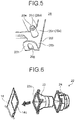
- FIG. 5 is a detail view of a supporting mechanism that holds the thermal insulating layer (thermal insulating unit).
- the duct joint 22 is configured to include an air passage unit 23 and a thermal insulating layer 24.
- the duct joint 22 is mounted on one of air passage openings 14c formed in the side panels 14a and 14b.
- the duct joints 22 are sorted into an indoor supply air opening, an exhaust air inlet, an exhaust air outlet, and an outside air inlet, in accordance with their installation positions.
- the air passage unit 23 includes a base section 23a that serves as a mounting base for mounting the duct joint 22 onto the side panels 14a and 14b and a cylindrical section 23b that is shaped into a cylinder.
- the inside of the cylindrical section 23b serves as an air passage through which a supply airflow or an exhaust airflow can pass from the thermal exchange ventilator 50.
- the outer diameter of the cylindrical section 23b is approximately 100 millimeters so that a duct of 100 millimeters in interior diameter can be connected thereto.
- supporting mechanisms 26 are provided at four positions to hold the thermal insulating layer 24.
- Each of the supporting mechanisms 26 is configured to include a protrusion 26a and an engaging unit 26b.
- the protrusion 26a is formed to protrude from the base section 23a, and has a stepped structure that includes a large cylinder 26c of a large diameter and a small cylinder 26d of a small diameter.
- a through hole 26e is formed in the protrusion 26a in such a manner to penetrate from the surface of the air passage unit 23 attached to the side panels 14a and 14b through the opposite surface thereof.
- the through hole 26e serves as a screw hole to attach the duct joint 22 to the side panels 14a and 14b.
- the engaging unit 26b is prepared in such a manner as to extend externally from the base section 23a.
- a groove 26f is formed at the border of the base section 23a and the engaging unit 26b.
- This groove 26f forms a hinge structure with which the engaging unit 26b can be bent along the groove 26f.
- the engaging unit 26b is not limited to the structure that is bendable along the groove 26f, but the structure may be such that it is bendable by use of a hinge or the like.
- the number of engaging units 26b arranged in the air passage unit 23 is not limited to four as indicated in the present embodiment, but it may be suitably changed.
- the engaging unit 26b has a tip portion 26h that is bent, forming an L shape in cross section.
- a U-shaped hole (exposed hole) 26g is formed in the tip portion 26h.
- the engaging unit 26b is bent along the groove 26f, the U-shaped hole 26g formed in the tip portion 26h is caught on the small cylinder 26d of the protrusion 26a so that the engaging unit 26b is engaged with the protrusion 26a.
- a certain space is created between the tip portion 26h and the base section 23a.
- the thermal insulating layer 24 is sandwiched and held in this space between the tip portion 26h and the base section 23a.
- the through hole 26e of the protrusion 26a is exposed from the U-shaped hole 26g.
- FIG. 6 is an exploded perspective view of the duct joint 22 viewed from the installation surface side.
- a guiding protrusion (positioning section) 23c is formed on the surface of the base section 23a attached to the side panels 14a and 14b to protrude therefrom.
- the guiding protrusion 23c is engaged with the air passage openings 14c when attaching the duct joint 22 to the side panels 14a and 14b so that the position of the duct joint 22 is determined.
- the thermal insulating layer 24 is stacked on the air passage unit 23 to cover the base section 23a and the cylindrical section 23b and has a function of preventing dew condensation from forming.
- a styrene-molded product may be adopted for the thermal insulating layer 24.
- a cylindrical section 24b that covers the cylindrical section 23b is configured to have a stepped structure that includes cylinders of different diameters. According to the present embodiment, cylinders of approximately 125 millimeters and 150 millimeters in outer diameters are formed.
- the external surface of the cylindrical section 24b of the thermal insulating layer 24 has a shape substantially the same as the shape of the external surface cut along a certain plane that is substantially parallel to the center axis of the cylindrical section 24b.
- the cylindrical portion of approximately 150 millimeters in outer diameter has a shape that is cut by a plane in contact with the lateral surface of the cylindrical portion of approximately 125 millimeters in outer diameter, which is a cylindrical portion one step smaller.
- Cut sections 24c are provided in such a manner as to oppose each other across the cylindrical section 24b. In other words, the cylindrical portion of approximately 150 millimeters in outer diameter is cut off 25 millimeters each from the two sides in the direction of the radius.
- the width of a tape for sealing the duct and the cylindrical section 24b is 50 millimeters. If the gap between the duct and the cylindrical section 24b exceeds 25 millimeters, the width of the portion of the tape overlaid and attached onto the duct portion for sealing the gap is reduced (to 10 millimeters, for example), which may lower the sealing performance. For this reason, it is favorable that the cut amount of the cylindrical section 24b be 25 millimeters or smaller in the direction of the radius.
- FIG. 7 is a plan view of the thermal exchange ventilator 50 and a side view thereof viewed from the direction of the duct joint 22.
- the cut sections 24c are arranged in part of the cylindrical section 24b so that when attaching the duct joint 22 to the thermal exchange ventilator 50, interference with the fastening hardware, the bottom panel 32, optionally obtainable components (attachments and damper units) 100, and the like can be avoided. In this manner, the outside dimension of the thermal exchange ventilator 50 can be minimized.
- the outer diameter of the cylindrical section 23b of the air passage unit 23 and the outer diameter of the cylindrical section 24b of the thermal insulating layer 24 are not limited to the ones specified in the present embodiment, but can be variously modified.
- a through hole for protection 24a is formed in the portion that covers the base section 23a.
- the protrusion 26a that is configured to protrude from the base section 23a penetrates the through hole for protection 24a, with the thermal insulating layer 24 laid on the air passage unit 23.
- the thermal insulating layer 24 is laid on the air passage unit 23.
- the position of the thermal insulating layer 24 can be readily determined simply by placing the protrusion 26a of the air passage unit 23 into the through hole for protection 24a formed in the thermal insulating layer 24.
- the duct joint 22 is assembled by bending the gripping unit 26b to engage with the protrusion 26a.
- the thermal insulating layer 24 gets caught and held in the certain space created between the tip portion 26h of the gripping unit 26b and the base section 23a of the air passage unit 23. In this manner, the thermal insulating layer 24 is tentatively fixed to the air passage unit 23.
- the assembled duct joint 22 is mounted on the air passage openings 14c of the side panels 14a and 14b.
- the duct joint 22 is screwed into the side panels 14a and 14b by means of the through hole 26e formed in the protrusion 26a.
- the thermal insulating layer 24 is tentatively fixed to the air passage unit 23, the air passage unit 23 and the thermal insulating layer 24 can be prevented from becoming separated from each other and coming off or getting lost, when mounting the duct joint 22 on the side panels 14a and 14b.
- a separate component for fixing the air passage unit 23 and the thermal insulating unit 24 to the thermal exchange ventilator 50 (such as the separate component 52c indicated in FIG. 8 ) is not required, which can realize light weight and cost reduction in accordance with the reduced number of components.
- the position of the duct joint 22 can be determined by inserting the guiding protrusion 23c formed on the base section 23a into the air passage openings 14c, and therefore low workability can be avoided even if visibility is insufficient, or if the foothold is unstable.
- the duct joint 22 is assembled in advance, there is no cumbersome alignment job such as aligning the screw holes of the air passage unit and the thermal insulating layer when the duct joint 22 is mounted, and the installation workability of the duct joint 22 can be further enhanced.
- the assembly of the duct joint 22 is completed simply by overlaying the air passage unit 23 and the thermal insulating layer 24 and then bending the gripping unit 26b, and thus no special tool is required and the assembly work can be simplified.
- the gripping unit 26b breaks along the groove 26f after the duct joint 22 is mounted on the side panels 14a and 14b, the mounting strength of the duct joint 22 can be maintained because the duct joint 22 is screwed down by way of the through hole 26e. Further, the tip portion 26h of the gripping unit 26b serves as a washer so that the thermal insulating layer 24 is prevented from falling off.
- the mounting position of the duct joint 22 can be changed by forming an air passage opening 31d in a side panel 31c.
- the position of the duct joint 22 can be changed in accordance with the layout of the building or the like.
- the duct joint 22 that is already mounted on the air passage opening 14c formed in the side panel 14a or 14b is to be rearranged onto the air passage opening 31d formed in the side panel 31c, the duct joint 22 that offers high workability is unlikely to cause problems of falling and losing of components, and the rearranging work can be readily conducted.
- the guiding protrusion 23c of the duct joint 22 is engaged with the air passage opening 31d also when it is mounted on the side panel 31c, and thereby delivers the positioning function.
- the duct joint according to the present invention is useful when it is mounted on the ventilator, and it is suitable especially for a heat exchanger that is allowed to change its installation position.
Landscapes
- Engineering & Computer Science (AREA)
- Chemical & Material Sciences (AREA)
- Combustion & Propulsion (AREA)
- Mechanical Engineering (AREA)
- General Engineering & Computer Science (AREA)
- Duct Arrangements (AREA)
- Thermal Insulation (AREA)
Claims (6)
- Kanalverbindung (22), die an einem Lüfter (50) befestigt ist, der Gebläse (3, 4) beinhaltet, an die ein Zuluft- oder Abluftkanal angebunden ist, umfassend:eine Luftdurchgangseinheit (23), durch die ein Zuluftstrom oder ein Abluftstrom von dem Lüfter (50) strömt; undeine Wärmeisolationseinheit (24), die auf die Luftdurchgangseinheit (23) gelegt ist und einen Umfang der Luftdurchgangseinheit (23) abdeckt,wobei ein Stützmechanismus (26) in der Luftdurchgangseinheit (23) angeordnet ist, um die Wärmeisolationseinheit (24) zu halten,dadurch gekennzeichnet, dassder Stützmechanismus umfasst:einen Vorsprung (26a), der in der Luftdurchgangseinheit (23) ausgebildet ist; undeine Eingriffseinheit (26b), die so ausgebildet ist, dass sie inBezug auf die Luftdurchgangseinheit (23) biegbar ist, unddie Eingriffseinheit (26b) mit dem Vorsprung (26a) in Eingriff steht, wenn die Eingriffseinheit (26b) gebogen ist, und die Wärmeisolationseinheit (24) hält, indem sie sie (24) in einem Raum zwischen der Eingriffseinheit (26b) und der Luftdurchgangseinheit (23) einfängt.
- Kanalverbindung (22) nach Anspruch 1, wobei:ein Durchgangsloch (26e) in dem Vorsprung (26a) so ausgebildet ist, dass es von einer Montagefläche der Luftdurchgangseinheit (23) in Bezug auf den Lüfter (50) durch eine gegenüberliegende Fläche davon dringt;ein freiliegendes Loch (26g) in der Eingriffseinheit (26b) ausgebildet ist, um das Durchgangsloch (26e) freizulegen, wenn es mit dem Vorsprung (26a) in Eingriff steht; unddie Luftdurchgangseinheit (23) so eingerichtet ist, dass die Luftdurchgangseinheit (23) über das Durchgangsloch (26e) in den Lüfter (50) einschraubbar ist, während sie die Wärmeisolationseinheit (24) hält.
- Kanalverbindung (22) nach Anspruch 1 oder 2, wobei in der Luftdurchgangseinheit (23) ein Positionierungsabschnitt (23c) ausgebildet ist, um eine Position der Luftdurchgangseinheit (23) in Bezug auf den Lüfter (50) zu bestimmen.
- Kanalverbindung (22) nach Anspruch 3, wobei der Positionierungsabschnitt (23c) eingerichtet ist, um von einer Montagefläche der Luftdurchgangseinheit (23) in Bezug auf den Lüfter (50) vorzustehen, und mit einer im Lüfter (50) ausgebildeten Öffnung (14c) in Eingriff steht, so dass die Position der Luftdurchgangseinheit (23) bestimmt wird.
- Kanalverbindung (22) nach einem der Ansprüche 1 bis 4, wobei:die Wärmeisolationseinheit (24) einen Zylinderabschnitt (24b) beinhaltet, der in einen Innenumfang eines zu verbindenden Kanals passt; undder Zylinderabschnitt eine Form aufweist, die im Wesentlichen die Gleiche ist wie eine Form, die durch Schneiden eines Umfangs eines Zylinders entlang einer bestimmten Ebene, die parallel zu einer Achse ist, erhalten wird.
- Lüfter (50), umfassend:ein kastenförmiges Gehäuse (1);Gebläse (3, 4), die in dem Gehäuse (1) enthalten sind: und die Kanalverbindung (22) nach einem der Ansprüche 1 bis 5, die an dem Gehäuse (1) befestigt ist.
Applications Claiming Priority (1)
| Application Number | Priority Date | Filing Date | Title |
|---|---|---|---|
| PCT/JP2009/056554 WO2010116466A1 (ja) | 2009-03-30 | 2009-03-30 | ダクト接続口および換気装置 |
Publications (3)
| Publication Number | Publication Date |
|---|---|
| EP2416079A1 EP2416079A1 (de) | 2012-02-08 |
| EP2416079A4 EP2416079A4 (de) | 2017-11-22 |
| EP2416079B1 true EP2416079B1 (de) | 2019-09-11 |
Family
ID=42935777
Family Applications (1)
| Application Number | Title | Priority Date | Filing Date |
|---|---|---|---|
| EP09842976.4A Active EP2416079B1 (de) | 2009-03-30 | 2009-03-30 | Kanalverbindungsöffnung und -lüftungsvorrichtung |
Country Status (6)
| Country | Link |
|---|---|
| EP (1) | EP2416079B1 (de) |
| JP (1) | JP5079137B2 (de) |
| KR (1) | KR101308820B1 (de) |
| CN (1) | CN102317695B (de) |
| TW (1) | TW201035500A (de) |
| WO (1) | WO2010116466A1 (de) |
Families Citing this family (5)
| Publication number | Priority date | Publication date | Assignee | Title |
|---|---|---|---|---|
| JP5818701B2 (ja) * | 2012-01-20 | 2015-11-18 | 三菱電機株式会社 | 換気装置 |
| JP6122281B2 (ja) * | 2012-11-12 | 2017-04-26 | ローヤル電機株式会社 | 換気装置及びその熱交換ユニット |
| CN105910219A (zh) * | 2016-06-07 | 2016-08-31 | 上海赛菲环境科技股份有限公司 | 换气装置及所适用的新风机 |
| JPWO2018220697A1 (ja) * | 2017-05-30 | 2019-11-07 | 三菱電機株式会社 | ダクト接続口及び換気装置 |
| JP7172502B2 (ja) * | 2018-11-27 | 2022-11-16 | 株式会社リコー | 送風装置、乾燥装置、印刷装置 |
Family Cites Families (9)
| Publication number | Priority date | Publication date | Assignee | Title |
|---|---|---|---|---|
| JP3169632B2 (ja) | 1991-06-20 | 2001-05-28 | 松下精工株式会社 | 熱交換形換気装置 |
| JPH07332727A (ja) * | 1994-06-06 | 1995-12-22 | Daikin Ind Ltd | 熱交換換気装置 |
| JP3456880B2 (ja) * | 1997-10-24 | 2003-10-14 | 松下エコシステムズ株式会社 | 換気装置 |
| JP2000171070A (ja) * | 1998-12-04 | 2000-06-23 | Matsushita Seiko Co Ltd | 換気空調ユニット |
| JP2003074936A (ja) * | 2001-08-30 | 2003-03-12 | Mitsubishi Electric Corp | 熱交換換気装置 |
| US7442120B2 (en) * | 2002-05-15 | 2008-10-28 | Imperial Sheet Metal Ltd. | Connection adapter for conduits and ventilation units |
| JP2005003345A (ja) * | 2003-05-21 | 2005-01-06 | Showa Denko Kk | 換気兼熱交換装置および空調システム |
| KR100700454B1 (ko) * | 2004-10-28 | 2007-03-28 | 삼성전자주식회사 | 환기장치 |
| JP2006242514A (ja) * | 2005-03-04 | 2006-09-14 | Max Co Ltd | 熱交換型換気装置 |
-
2009
- 2009-03-30 EP EP09842976.4A patent/EP2416079B1/de active Active
- 2009-03-30 JP JP2011508108A patent/JP5079137B2/ja active Active
- 2009-03-30 CN CN200980156521.3A patent/CN102317695B/zh not_active Expired - Fee Related
- 2009-03-30 WO PCT/JP2009/056554 patent/WO2010116466A1/ja not_active Ceased
- 2009-03-30 KR KR1020117022022A patent/KR101308820B1/ko not_active Expired - Fee Related
- 2009-06-06 TW TW098118890A patent/TW201035500A/zh not_active IP Right Cessation
Non-Patent Citations (1)
| Title |
|---|
| None * |
Also Published As
| Publication number | Publication date |
|---|---|
| CN102317695A (zh) | 2012-01-11 |
| EP2416079A4 (de) | 2017-11-22 |
| TW201035500A (en) | 2010-10-01 |
| EP2416079A1 (de) | 2012-02-08 |
| JPWO2010116466A1 (ja) | 2012-10-11 |
| JP5079137B2 (ja) | 2012-11-21 |
| TWI372845B (de) | 2012-09-21 |
| KR101308820B1 (ko) | 2013-09-13 |
| WO2010116466A1 (ja) | 2010-10-14 |
| KR20110124778A (ko) | 2011-11-17 |
| CN102317695B (zh) | 2014-02-05 |
Similar Documents
| Publication | Publication Date | Title |
|---|---|---|
| KR101001436B1 (ko) | 천장 매립형 공기 조화 장치의 실내기 | |
| EP2120524B1 (de) | Kühlvorrichtung | |
| KR101203998B1 (ko) | 열교환기와 이를 가지는 환기장치 | |
| EP2416079A1 (de) | Kanalverbindungsöffnung und -lüftungsvorrichtung | |
| EP2565547A1 (de) | Außenraumeinheit für Klimaanlage | |
| WO2016203542A1 (ja) | 空気調和機の室外機 | |
| US7627999B2 (en) | Prefabricated fixture protection cover and assembly and method of use thereof | |
| JP2010159909A (ja) | 空気調和装置 | |
| JP6037887B2 (ja) | 熱交換換気装置 | |
| WO2022260577A2 (en) | A transit device for leading one or more cables and/or pipes through an opening in a partition | |
| US11351759B2 (en) | Insulating panel for an insulated air-flow casing and insulated air-flow casing comprising such an insulating panel | |
| JP3101485B2 (ja) | 空気調和装置 | |
| JP2011163564A (ja) | 空気調和機の室内ユニット | |
| JP5197455B2 (ja) | 天井カセット形空気調和機 | |
| JP4833048B2 (ja) | 送風端末装置 | |
| JP4141368B2 (ja) | 天井埋込型空気調和装置 | |
| JP4500148B2 (ja) | 遮熱材の設置構造 | |
| CN213426698U (zh) | 一种电控箱箱体 | |
| JP6214504B2 (ja) | 熱交換換気装置 | |
| JP2008095978A (ja) | 空気調和機の室外機 | |
| EP4253857B1 (de) | Lüftungsvorrichtung | |
| JP5454550B2 (ja) | 換気装置 | |
| JP2011069530A (ja) | 熱交換器及びこの熱交換器を備えた空間調和装置 | |
| JP2006349317A (ja) | 空気調和機の組み立て方法および空気調和機 | |
| JP4271100B2 (ja) | 吹出チャンバ装置およびこれを用いたビルトイン型空気調和機 |
Legal Events
| Date | Code | Title | Description |
|---|---|---|---|
| PUAI | Public reference made under article 153(3) epc to a published international application that has entered the european phase |
Free format text: ORIGINAL CODE: 0009012 |
|
| 17P | Request for examination filed |
Effective date: 20110816 |
|
| AK | Designated contracting states |
Kind code of ref document: A1 Designated state(s): AT BE BG CH CY CZ DE DK EE ES FI FR GB GR HR HU IE IS IT LI LT LU LV MC MK MT NL NO PL PT RO SE SI SK TR |
|
| DAX | Request for extension of the european patent (deleted) | ||
| RA4 | Supplementary search report drawn up and despatched (corrected) |
Effective date: 20171024 |
|
| RIC1 | Information provided on ipc code assigned before grant |
Ipc: F24F 12/00 20060101ALI20171018BHEP Ipc: F24F 7/08 20060101AFI20171018BHEP Ipc: F24F 13/02 20060101ALI20171018BHEP |
|
| RIC1 | Information provided on ipc code assigned before grant |
Ipc: F24F 12/00 20060101ALI20180205BHEP Ipc: F24F 7/08 20060101AFI20180205BHEP Ipc: F24F 13/02 20060101ALI20180205BHEP |
|
| GRAP | Despatch of communication of intention to grant a patent |
Free format text: ORIGINAL CODE: EPIDOSNIGR1 |
|
| STAA | Information on the status of an ep patent application or granted ep patent |
Free format text: STATUS: GRANT OF PATENT IS INTENDED |
|
| INTG | Intention to grant announced |
Effective date: 20190402 |
|
| GRAS | Grant fee paid |
Free format text: ORIGINAL CODE: EPIDOSNIGR3 |
|
| GRAA | (expected) grant |
Free format text: ORIGINAL CODE: 0009210 |
|
| STAA | Information on the status of an ep patent application or granted ep patent |
Free format text: STATUS: THE PATENT HAS BEEN GRANTED |
|
| AK | Designated contracting states |
Kind code of ref document: B1 Designated state(s): AT BE BG CH CY CZ DE DK EE ES FI FR GB GR HR HU IE IS IT LI LT LU LV MC MK MT NL NO PL PT RO SE SI SK TR |
|
| REG | Reference to a national code |
Ref country code: GB Ref legal event code: FG4D |
|
| REG | Reference to a national code |
Ref country code: CH Ref legal event code: EP |
|
| REG | Reference to a national code |
Ref country code: AT Ref legal event code: REF Ref document number: 1178926 Country of ref document: AT Kind code of ref document: T Effective date: 20190915 |
|
| REG | Reference to a national code |
Ref country code: DE Ref legal event code: R096 Ref document number: 602009059842 Country of ref document: DE Ref country code: IE Ref legal event code: FG4D |
|
| REG | Reference to a national code |
Ref country code: SE Ref legal event code: TRGR |
|
| REG | Reference to a national code |
Ref country code: NL Ref legal event code: MP Effective date: 20190911 |
|
| REG | Reference to a national code |
Ref country code: LT Ref legal event code: MG4D |
|
| PG25 | Lapsed in a contracting state [announced via postgrant information from national office to epo] |
Ref country code: HR Free format text: LAPSE BECAUSE OF FAILURE TO SUBMIT A TRANSLATION OF THE DESCRIPTION OR TO PAY THE FEE WITHIN THE PRESCRIBED TIME-LIMIT Effective date: 20190911 Ref country code: NO Free format text: LAPSE BECAUSE OF FAILURE TO SUBMIT A TRANSLATION OF THE DESCRIPTION OR TO PAY THE FEE WITHIN THE PRESCRIBED TIME-LIMIT Effective date: 20191211 Ref country code: FI Free format text: LAPSE BECAUSE OF FAILURE TO SUBMIT A TRANSLATION OF THE DESCRIPTION OR TO PAY THE FEE WITHIN THE PRESCRIBED TIME-LIMIT Effective date: 20190911 Ref country code: BG Free format text: LAPSE BECAUSE OF FAILURE TO SUBMIT A TRANSLATION OF THE DESCRIPTION OR TO PAY THE FEE WITHIN THE PRESCRIBED TIME-LIMIT Effective date: 20191211 Ref country code: LT Free format text: LAPSE BECAUSE OF FAILURE TO SUBMIT A TRANSLATION OF THE DESCRIPTION OR TO PAY THE FEE WITHIN THE PRESCRIBED TIME-LIMIT Effective date: 20190911 |
|
| PG25 | Lapsed in a contracting state [announced via postgrant information from national office to epo] |
Ref country code: LV Free format text: LAPSE BECAUSE OF FAILURE TO SUBMIT A TRANSLATION OF THE DESCRIPTION OR TO PAY THE FEE WITHIN THE PRESCRIBED TIME-LIMIT Effective date: 20190911 Ref country code: ES Free format text: LAPSE BECAUSE OF FAILURE TO SUBMIT A TRANSLATION OF THE DESCRIPTION OR TO PAY THE FEE WITHIN THE PRESCRIBED TIME-LIMIT Effective date: 20190911 Ref country code: GR Free format text: LAPSE BECAUSE OF FAILURE TO SUBMIT A TRANSLATION OF THE DESCRIPTION OR TO PAY THE FEE WITHIN THE PRESCRIBED TIME-LIMIT Effective date: 20191212 |
|
| REG | Reference to a national code |
Ref country code: AT Ref legal event code: MK05 Ref document number: 1178926 Country of ref document: AT Kind code of ref document: T Effective date: 20190911 |
|
| PG25 | Lapsed in a contracting state [announced via postgrant information from national office to epo] |
Ref country code: NL Free format text: LAPSE BECAUSE OF FAILURE TO SUBMIT A TRANSLATION OF THE DESCRIPTION OR TO PAY THE FEE WITHIN THE PRESCRIBED TIME-LIMIT Effective date: 20190911 Ref country code: PT Free format text: LAPSE BECAUSE OF FAILURE TO SUBMIT A TRANSLATION OF THE DESCRIPTION OR TO PAY THE FEE WITHIN THE PRESCRIBED TIME-LIMIT Effective date: 20200113 Ref country code: PL Free format text: LAPSE BECAUSE OF FAILURE TO SUBMIT A TRANSLATION OF THE DESCRIPTION OR TO PAY THE FEE WITHIN THE PRESCRIBED TIME-LIMIT Effective date: 20190911 Ref country code: RO Free format text: LAPSE BECAUSE OF FAILURE TO SUBMIT A TRANSLATION OF THE DESCRIPTION OR TO PAY THE FEE WITHIN THE PRESCRIBED TIME-LIMIT Effective date: 20190911 Ref country code: EE Free format text: LAPSE BECAUSE OF FAILURE TO SUBMIT A TRANSLATION OF THE DESCRIPTION OR TO PAY THE FEE WITHIN THE PRESCRIBED TIME-LIMIT Effective date: 20190911 Ref country code: AT Free format text: LAPSE BECAUSE OF FAILURE TO SUBMIT A TRANSLATION OF THE DESCRIPTION OR TO PAY THE FEE WITHIN THE PRESCRIBED TIME-LIMIT Effective date: 20190911 Ref country code: IT Free format text: LAPSE BECAUSE OF FAILURE TO SUBMIT A TRANSLATION OF THE DESCRIPTION OR TO PAY THE FEE WITHIN THE PRESCRIBED TIME-LIMIT Effective date: 20190911 |
|
| PG25 | Lapsed in a contracting state [announced via postgrant information from national office to epo] |
Ref country code: CZ Free format text: LAPSE BECAUSE OF FAILURE TO SUBMIT A TRANSLATION OF THE DESCRIPTION OR TO PAY THE FEE WITHIN THE PRESCRIBED TIME-LIMIT Effective date: 20190911 Ref country code: IS Free format text: LAPSE BECAUSE OF FAILURE TO SUBMIT A TRANSLATION OF THE DESCRIPTION OR TO PAY THE FEE WITHIN THE PRESCRIBED TIME-LIMIT Effective date: 20200224 Ref country code: SK Free format text: LAPSE BECAUSE OF FAILURE TO SUBMIT A TRANSLATION OF THE DESCRIPTION OR TO PAY THE FEE WITHIN THE PRESCRIBED TIME-LIMIT Effective date: 20190911 |
|
| REG | Reference to a national code |
Ref country code: DE Ref legal event code: R097 Ref document number: 602009059842 Country of ref document: DE |
|
| PLBE | No opposition filed within time limit |
Free format text: ORIGINAL CODE: 0009261 |
|
| STAA | Information on the status of an ep patent application or granted ep patent |
Free format text: STATUS: NO OPPOSITION FILED WITHIN TIME LIMIT |
|
| PG2D | Information on lapse in contracting state deleted |
Ref country code: IS |
|
| PG25 | Lapsed in a contracting state [announced via postgrant information from national office to epo] |
Ref country code: DK Free format text: LAPSE BECAUSE OF FAILURE TO SUBMIT A TRANSLATION OF THE DESCRIPTION OR TO PAY THE FEE WITHIN THE PRESCRIBED TIME-LIMIT Effective date: 20190911 Ref country code: IS Free format text: LAPSE BECAUSE OF FAILURE TO SUBMIT A TRANSLATION OF THE DESCRIPTION OR TO PAY THE FEE WITHIN THE PRESCRIBED TIME-LIMIT Effective date: 20200112 |
|
| 26N | No opposition filed |
Effective date: 20200615 |
|
| PG25 | Lapsed in a contracting state [announced via postgrant information from national office to epo] |
Ref country code: SI Free format text: LAPSE BECAUSE OF FAILURE TO SUBMIT A TRANSLATION OF THE DESCRIPTION OR TO PAY THE FEE WITHIN THE PRESCRIBED TIME-LIMIT Effective date: 20190911 |
|
| PG25 | Lapsed in a contracting state [announced via postgrant information from national office to epo] |
Ref country code: MC Free format text: LAPSE BECAUSE OF FAILURE TO SUBMIT A TRANSLATION OF THE DESCRIPTION OR TO PAY THE FEE WITHIN THE PRESCRIBED TIME-LIMIT Effective date: 20190911 |
|
| REG | Reference to a national code |
Ref country code: CH Ref legal event code: PL |
|
| REG | Reference to a national code |
Ref country code: BE Ref legal event code: MM Effective date: 20200331 |
|
| PG25 | Lapsed in a contracting state [announced via postgrant information from national office to epo] |
Ref country code: LU Free format text: LAPSE BECAUSE OF NON-PAYMENT OF DUE FEES Effective date: 20200330 |
|
| PG25 | Lapsed in a contracting state [announced via postgrant information from national office to epo] |
Ref country code: IE Free format text: LAPSE BECAUSE OF NON-PAYMENT OF DUE FEES Effective date: 20200330 Ref country code: LI Free format text: LAPSE BECAUSE OF NON-PAYMENT OF DUE FEES Effective date: 20200331 Ref country code: CH Free format text: LAPSE BECAUSE OF NON-PAYMENT OF DUE FEES Effective date: 20200331 Ref country code: FR Free format text: LAPSE BECAUSE OF NON-PAYMENT OF DUE FEES Effective date: 20200331 |
|
| PG25 | Lapsed in a contracting state [announced via postgrant information from national office to epo] |
Ref country code: BE Free format text: LAPSE BECAUSE OF NON-PAYMENT OF DUE FEES Effective date: 20200331 |
|
| PGFP | Annual fee paid to national office [announced via postgrant information from national office to epo] |
Ref country code: DE Payment date: 20210316 Year of fee payment: 13 |
|
| PG25 | Lapsed in a contracting state [announced via postgrant information from national office to epo] |
Ref country code: TR Free format text: LAPSE BECAUSE OF FAILURE TO SUBMIT A TRANSLATION OF THE DESCRIPTION OR TO PAY THE FEE WITHIN THE PRESCRIBED TIME-LIMIT Effective date: 20190911 Ref country code: MT Free format text: LAPSE BECAUSE OF FAILURE TO SUBMIT A TRANSLATION OF THE DESCRIPTION OR TO PAY THE FEE WITHIN THE PRESCRIBED TIME-LIMIT Effective date: 20190911 Ref country code: CY Free format text: LAPSE BECAUSE OF FAILURE TO SUBMIT A TRANSLATION OF THE DESCRIPTION OR TO PAY THE FEE WITHIN THE PRESCRIBED TIME-LIMIT Effective date: 20190911 |
|
| PG25 | Lapsed in a contracting state [announced via postgrant information from national office to epo] |
Ref country code: MK Free format text: LAPSE BECAUSE OF FAILURE TO SUBMIT A TRANSLATION OF THE DESCRIPTION OR TO PAY THE FEE WITHIN THE PRESCRIBED TIME-LIMIT Effective date: 20190911 |
|
| REG | Reference to a national code |
Ref country code: DE Ref legal event code: R119 Ref document number: 602009059842 Country of ref document: DE |
|
| REG | Reference to a national code |
Ref country code: GB Ref legal event code: 746 Effective date: 20221229 |
|
| PG25 | Lapsed in a contracting state [announced via postgrant information from national office to epo] |
Ref country code: DE Free format text: LAPSE BECAUSE OF NON-PAYMENT OF DUE FEES Effective date: 20221001 |
|
| P01 | Opt-out of the competence of the unified patent court (upc) registered |
Effective date: 20230512 |
|
| PGFP | Annual fee paid to national office [announced via postgrant information from national office to epo] |
Ref country code: GB Payment date: 20240208 Year of fee payment: 16 |
|
| PGFP | Annual fee paid to national office [announced via postgrant information from national office to epo] |
Ref country code: SE Payment date: 20240212 Year of fee payment: 16 |
|
| REG | Reference to a national code |
Ref country code: SE Ref legal event code: EUG |
|
| GBPC | Gb: european patent ceased through non-payment of renewal fee |
Effective date: 20250330 |
|
| PG25 | Lapsed in a contracting state [announced via postgrant information from national office to epo] |
Ref country code: GB Free format text: LAPSE BECAUSE OF NON-PAYMENT OF DUE FEES Effective date: 20250330 |
|
| PG25 | Lapsed in a contracting state [announced via postgrant information from national office to epo] |
Ref country code: SE Free format text: LAPSE BECAUSE OF NON-PAYMENT OF DUE FEES Effective date: 20250331 |