EP2401928A2 - Dispositif de fabrication de produits en forme de tiges de l'industrie de traitement du tabac - Google Patents
Dispositif de fabrication de produits en forme de tiges de l'industrie de traitement du tabac Download PDFInfo
- Publication number
- EP2401928A2 EP2401928A2 EP11004862A EP11004862A EP2401928A2 EP 2401928 A2 EP2401928 A2 EP 2401928A2 EP 11004862 A EP11004862 A EP 11004862A EP 11004862 A EP11004862 A EP 11004862A EP 2401928 A2 EP2401928 A2 EP 2401928A2
- Authority
- EP
- European Patent Office
- Prior art keywords
- tobacco rod
- scraper
- base
- tobacco
- format
- Prior art date
- Legal status (The legal status is an assumption and is not a legal conclusion. Google has not performed a legal analysis and makes no representation as to the accuracy of the status listed.)
- Withdrawn
Links
Images

Classifications
-
- A—HUMAN NECESSITIES
- A24—TOBACCO; CIGARS; CIGARETTES; SIMULATED SMOKING DEVICES; SMOKERS' REQUISITES
- A24C—MACHINES FOR MAKING CIGARS OR CIGARETTES
- A24C5/00—Making cigarettes; Making tipping materials for, or attaching filters or mouthpieces to, cigars or cigarettes
- A24C5/14—Machines of the continuous-rod type
- A24C5/18—Forming the rod
- A24C5/1807—Forming the rod with compressing means, e.g. garniture
Definitions
- the invention relates to a device for the production of rod-shaped products of the tobacco processing industry having the features of the preamble of claim 1 and a scraper for such a device having the features of one of the preambles of claim 9 or 11.
- Rod-shaped products of the tobacco processing industry are e.g. Cigarettes or cigarillos, which are produced by machine from a continuously fed tobacco rod, which is placed on an equally continuously supplied wrapping web and is then fixed by laying the wrapping web around the tobacco rod to a rod-shaped strand. The rod-shaped products are then cut in a predetermined length of the strand.
- the tobacco is first sucked in the device by means of a negative pressure, porous, endless conveyor belt from a supply or a homogenization chamber and conveyed to a trimming device.
- the trimming device is formed by one or two rotating cutting disks located at a constant distance from the conveyor belt, which can have, for example, depressions distributed regularly over the circumference.
- the cutting wheels are aligned with the conveyor belt so that they separate the tobacco rod during rotation from the adhering to the conveyor belt tobacco mass at a predetermined height.
- the recesses in the cutting discs have it the task of creating regularly spaced portions with a larger cross-section in the tobacco rod, which form the heads of the tobacco rod in the finished product after the completion of the rod-shaped products.
- the free end or free ends of the tobacco rod designates the filter-facing end of the tobacco rod in the finished product. If cut-off wheels without depressions are used, the sections with the enlarged cross-sections are provided by means provided on the side of the tobacco rod for changing the geometry of the tobacco rod.
- the tobacco rod After passing through the trimming device, the tobacco rod has a non-round, preferably rectangular cross-section and is separated from the conveyor belt by a scraper for release from the conveyor belt on a deflection roller. Due to the concerns of the conveyor belt on the pulley this is no longer acted upon by the vacuum, so that the force acting on the tobacco rod holding force decreases and finally no longer exists. As a result, the tobacco rod already dissolves itself from the conveyor belt and is then continued by the scraper. Nevertheless, the scraper should be arranged as close as possible to the deflection roller, without touching the conveyor belt, so that the movement of the tobacco strand in the further course of the conveyor belt is guided on a transported from a format tape wrapping, and to free the conveyor belt of dirt.
- the tobacco rod separated from the conveyor belt is placed on a continuously supplied wrapping web, which is placed around the tobacco rod and glued together at their lateral edges.
- the wrapping web is placed on a further transport movement effecting format tape, which is guided on a format background with a profiled surface.
- the surface of the format base is profiled in such a way that the edge of the wrapping web is pushed up laterally of the tobacco rod, so that the tobacco rod is prefixed in the formed groove, and at one of the edges a glue trace enabling the subsequent bonding can be applied.
- the scraper next to the separation of the tobacco rod has the additional task to convert the cross-section not round tobacco rod at the top at least in a preform with a part-circular cross-section and has to a transition from a flat surface in a curved surface surface.
- a finger In the transport direction behind the scraper is directly followed by a finger, which completes the shaping of the top of the tobacco rod to a circle segment before the shape of the tobacco rod is fixed by the wrapping and gluing of the wrapping web.
- the scraper and the finger can be formed in one piece, with a separate embodiment has the advantage that the scraper and the finger can be replaced separately as wearing parts.
- the tobacco rod of the rectangular or non-round cross-sectional shape having a first cross-sectional area and regular portions having a larger second cross-sectional area is converted into a rod-shaped form having a constant diameter.
- the tobacco rod is at least partially compressed, in which case the sections with the larger cross-sectional area, so the heads are compressed more. This higher compression can be done in the worst case Incorrect settings lead to a tearing of the tobacco rod by the higher contact pressure or to shift the relative position of the heads in the tobacco rod.
- the continuous manufacturing process In the event that the tobacco rod breaks or builds up, the continuous manufacturing process must be stopped, the device stopped and the tobacco rod guide path cleaned before restarting the device.
- the relative position of the heads in the tobacco rod is not changed by the compression, and that the heads after production have a predetermined density, so that the so-called head failure does not exceed a predetermined amount of tobacco.
- the length of the heads in the finished products also does not correspond to the predetermined length, so that the predetermined limit for the head failure can be exceeded.
- head failure is understood to mean the amount of tobacco particles which falls out of the end of the product not covered by a filter in the further production process up to the final packaging.
- the predetermined, not to be exceeded head loss is a decisive quality criterion for the product itself, which is required by the manufacturer of the products. Excessive head failure can also lead to disturbances in the subsequent processing of the products by the falling out tobacco particles pollute functional areas of the device.
- the scraper and the finger are subject to a variety of requirements for the above reasons and are for the maintenance of quality criteria and trouble-free continuous operation of the device very important items that must be checked at regular intervals and replaced if necessary.
- a generic device is for example from the DE 34 07 068 A1 in which a scraper designated there as a compression shoe is provided, to which a finger designated there as a tongue part connects.
- the finger has a contact surface converging in the direction of the transport direction of the tobacco rod to a base surface with a plurality of frusto-conical sections.
- the frusto-conical sections are intended to prevent excessive heating of the finger and the consequent adherence of tar.
- the shape of the scraper is not described in detail; however, it is believed that the shape of the scraper is also converging since it was called a "compression shoe".
- the object of the invention is to provide a device with which a production of rod-shaped products of the tobacco-processing industry with a reliably below a limit remaining head loss is possible.
- a device for the production of rod-shaped products of the tobacco-processing industry with a conveyor for continuously feeding a tobacco rod with a first cross-sectional area, which has sections with a larger second cross-sectional area at regular intervals, wherein the conveyor by a guided over a pulley Continuous conveyor belt is formed, on which the tobacco rod is arranged, and a run on a format basis format tape on which a continuously fed wrapping web, and a tobacco rod of the endless conveyor belt separating scraper, which has such a profiled base, the non-circular in cross-section tobacco rod is deformed when passing on the base to a tobacco rod with a curved outer surface proposed, in which the distance between the base and the Format ground in the transport direction of the T abakstranges increases, in the transport direction of the tobacco rod behind the scraper, a finger is provided, which has a contact surface, and the base and the contact surface without a gap merge into each other.
- the term of the base of the scraper is to be understood as the area in which the lowest points of the profiled surface are arranged. If the scraper has a profiled surface that merges into a groove from a plane, the base area of the scraper would be the surface in which first the plane surface of the scraper is located on the inlet side of the tobacco rod and in the further course the lowest points of the groove. If no such area is definable, the base area is the average area between the lowest points.
- the base of the scraper in the transport direction of the tobacco rod is basically aligned either parallel to the format base or converging to this.
- Such a solution initially seems to make sense, since the tobacco rod must be pressed into the ultimately rod-shaped mold with a constant diameter.
- the proposed solution according to the invention deviates from this principle and suggests that the distance should increase, so that the base is arranged diverging to the format reason.
- This allows an initially seemingly unrealistic widening of the tobacco rod.
- This widening of the tobacco rod prevents the tobacco rod is compressed in particular in the region of the heads over a longer portion of the transport path so far that changes the relative position of the heads in the tobacco rod, in particular their location in the tobacco composite to tobacco rod.
- the deviations in the length of the heads in the product are also less, which can further reduce head loss. Furthermore, the frictional forces are reduced by the inventive solution, so that the scraper heats itself less. Due to the gap-free merging base and contact surface of the tobacco rod is passed directly to the contact surface after the brief expansion of the base in the transport direction of the tobacco rod, so that the shape of the tobacco rod at the contact surface directly adjoins the expansion of the base, without the tobacco rod can deform or expand in an intermediate phase uncontrolled.
- the term "gap-free" refers to an immediate within the meaning of the invention Connection of the contact surface in the transport direction of the tobacco rod to the base.
- the base surface is arranged at an angle of 0.5 to 6.0 degrees, preferably from 2.0 to 4.5 degrees to the format base.
- the proposed angular ranges have been found to be advantageous in a number of test series with different types of tobacco, wherein it is particularly important that the tobacco distribution predetermined by the trimming device when separating the tobacco rod from the tobacco volume and the subsequently resulting density distribution of the tobacco rod are not lost in the further processing process goes.
- the distance between the contact surface and the format base decreases in the transport direction of the tobacco rod.
- the finger has the task to shape the top of the voltage applied to the contact surface tobacco rod to a circular segment with a predetermined radius. Because of the inventively proposed increasing distance between the format base and the base of the scraper and the decreasing distance between the contact surface of the finger and the format base, the first by the shape of the base expanded tobacco rod can be deformed at the contact surface of the finger with a much greater degree of deformation, than is possible with the solutions known in the art.
- the scraper and the finger can preferably be formed in one piece, whereby a much more accurate arrangement of the base to the contact surface of the finger can be realized because the tolerance chain is at least shortened by the one-piece arrangement.
- the distance between the contact surface on the side of the finger at which the tobacco rod emerges and the format base corresponds to the diameter of the finished rod-shaped product minus 0.6 - 1.5 mm.
- the proposed distance has also proved to be ideal, especially with regard to the proposed geometry of the doctor, for a continuous and trouble-free production of the rod-shaped products.
- a trimming device which is formed by one or more cutting discs, by means of which the tobacco rod can be separated from a tobacco volume, and the distance between the cutting discs and the endless conveyor belt and the distance between the last in the transport direction of the tobacco rod pulley, on which the endless conveyor belt rests, and the format reason minus the thickness of the conveyor belt applied to the deflection roller, the thickness of a wrapping web on which the tobacco rod rests, and the thickness of a resting on the format base format strip within a tolerance of +/- 0.5 mm are identical.
- the scraper and / or the finger is or are formed from a thick-walled component without cavities, at least in the area of the base area and / or the area of the contact surface.
- the proposed solution allows a very precise component processing and also a high dimensional stability of the scraper and the finger even after a longer higher mechanical and thermal stress.
- the distance of the deflection roller to the format base thus simultaneously corresponds to the height which defines the first cross-sectional area of the tobacco rod. Due to the distance between the last in the transport direction of the tobacco strand pulley and the format reason is determined at the same time, with which pressing force of the tobacco rod is pressed onto the wrapping path located on the format tape.
- the deflection roller defines a transfer point, from which the tobacco rod is transported for further transport on the wrapping web of the format tape. For this reason, it is of particular importance for trouble-free operation of the device that the tobacco rod is transported continuously through the device at the transfer point.
- the proposed distance of the pulley has been found in this regard to be ideal for the transport conditions, since the tobacco rod is thereby pressed for its trouble-free transfer with a sufficient contact pressure on the wrapping, without causing the risk of tearing or damming the tobacco rod.
- the proposed distance of the deflection roller from the format base the transport of the tobacco rod can be improved regardless of the shape and orientation of the scraper.
- a scraper for a device for producing rod-shaped products of the tobacco processing industry for separating a continuously fed tobacco rod from an endless conveyor belt which has a contact surface for abutment with the device and a base surface at which the tobacco rod comes to rest, and Angle between the contact surface and the base surface is greater than 90 degrees.
- the advantage of the proposed scraper is the fact that the scraper is designed so that the inventive Advantage is made possible by the alignment of the base alone by the scraper itself. All that is required is a contact surface, which is oriented perpendicular to the format base, on the device on which the scraper can be arranged. The angle of the base to the tobacco rod or to the format reason is then automatically given by the angle of the base to the contact surface. In particular, this makes it possible to realize different angles individually in a standard machine according to the customer requirements or depending on the type of tobacco to be processed by the scraper is replaced and replaced by a scraper with a different angle between the base and the contact surface.
- the angle between the base surface and the contact surface should be 90.5 to 96.0 degrees, preferably 92 to 94.5 degrees.
- a scraper for a device for the production of rod-shaped products of the tobacco-processing industry for separating a continuously fed tobacco rod is proposed by an endless conveyor belt, which in the mounting position of the scraper to the perpendicular skewed contact surface for abutment with the device, and a Base area, where the tobacco rod comes to rest, and the angle between the contact surface and the base surface is less than 90 degrees, and the sum of the angle between the contact surface and the vertical and the angle between the contact surface and the base greater than 90 Degree is.
- the proposed scraper allows the same inventive success as the scraper proposed according to claim 7, with the difference that the proposed scraper can also be arranged on a perpendicular to the vertical oblique contact surface of the device.
- a finger is integrally formed on the inventively proposed scrapers. Due to the one-piece design of the scraper and the finger, these can be exchanged together in one step. In addition, the tolerance chain is shortened by the no longer existing contact surface by a degree, so that the base and the contact surface of the finger can be realized with a much higher accuracy to each other.
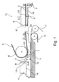
- FIG. 1 a device according to the invention can be seen, in which a disordered tobacco volume 7 homogenized in an upstream homogenizing device is sucked by means of negative pressure from a porous endless conveyor belt 5.
- a weight control shoe 9 On one side of the endless conveyor belt 5 is a weight control shoe 9, which is movable in the direction of arrow C.
- a trimmer 14 On the opposite side of the endless conveyor belt 5 is a trimmer 14 in the form of one or more rotating Cutting discs each provided with one or more recesses 8. The distance between the endless conveyor belt 5 and the trimming device 14 can be changed by moving the weight control shoe 9 in the direction of arrow C.
- the endless conveyor belt 5 wraps around in the course of a deflection roller 6 and is driven by a drive device, not shown, to move in the direction of arrow D.
- the adhering tobacco volume 7 is pulled in the direction of the trimming device 14 and thereby cut by the rotating cutting discs to a tobacco rod 2.
- the tobacco rod 2 after cutting has a first cross-sectional area defined by the first height x1 and regular portions 2a having a larger cross-sectional area defined by the one second height x2.
- the first height x1 is predetermined by the set distance between the cutting wheel and the endless conveyor belt 5, while the second height x2 is predetermined by the first height x1 plus the dimension of the recess 8.
- the first height x1 and the second height x2 are therefore directly related due to the unalterable dimension of the recess 8.
- the sections 2a with the greater height x2 form the heads of the tobacco rod 2 located in the product after the production of the rod-shaped products.
- the tobacco rod 2 to the transport direction T of the tobacco rod 2 last pulley 6, at which the endless conveyor belt 5 is applied, and runs on a continuously supplied, wrapping web 11.
- the wrapping web 11 is guided by a in the transport direction T driven format tape 10, which in turn rests on a Formatground 1.
- the Formatground 1 forms a support surface and is corresponding to the rod-shaped product to be formed with a groove with a continuous provided in decreasing radius, in which the format strip 10 is guided with the wrapping web 11 and the tobacco rod 2 laid thereon.
- the deflection roller 6 is aligned at a distance x3 to the format base 1, which minus the thickness of the endless conveyor belt 5, the thickness of the wrapping web 11 and the thickness of the format strip 10 of the first height x1 of the tobacco rod 2 within a tolerance of +/- 0.5 mm corresponds.
- the proposed distance of the deflection roller 6 to the format base 1 has been found to be ideal for the further continuous transport of the tobacco rod 2.
- the scraper 3 is provided with a base 12 which is shaped such that the distance between the base 12 and the format base 1 in the transport direction T of the tobacco rod 2 increases.
- the increase of the distance is in the presentation represented as angle A greater than 0 degrees.
- the scraper 3 is further provided with an aligned in the mounting position perpendicular to the format base 1 contact surface 15, so that the increasing distance between the base 12 and the format reason 1 by the angle B between the base 12 and the contact surface 15 of preferably 90th , 5 to 96 degrees and in particular from 92 to 94.5 degrees.
- the angle A can be changed particularly easily by the use of a scraper 3 with a different angle B.
- the contact surface 15 of the scraper 3 is in the attachment position in contact with a likewise perpendicular to the format base 1 aligned contact surface of a finger 4, which is arranged in the transport direction T of the tobacco rod 2 behind the scraper 3.
- the finger 4 is provided on its side facing the format base 1 with a contact surface 14, which is shaped such that the distance between the contact surface 14 and the format base 1 decreases in the transport direction T.
- a step, formed by a material surplus of the base surface 12 is expediently provided, which represents a wear reserve and prevents the tobacco rod 2 from starting with the surface against an edge of the contact surface 14.
- the angle B can also be chosen smaller than 90 degrees, in which case the sum of the angle between the contact surface 15 and the vertical and the angle B larger than 90 degrees should be to bring about the success of the invention.
- the finger 4 is arranged directly on the scraper 3, so that there is no gap between the two parts in the transport direction T of the tobacco rod.
- the base 12 is thereby in the transport direction T directly into the contact surface 14 via. Since the scraper 3 and the finger 4 are each designed as thick-walled components without cavities, they can be made very accurately from a solid material. As a manufacturing process to offer all metal cutting processes and erosion. Furthermore, the components can be dimensioned such that the base surface 12 and contact surface 14 arranged thereon have a high dimensional accuracy even with high mechanical and thermal stress.
- the shape of the tobacco rod 2 takes place on the one hand by the channel located in the format 1 and on the other hand by the profiled base 12 of the scraper and the contact surface 14 of the finger 4. Since the distance between the base 12 and the format base 1 increases in the transport direction T, can the tobacco rod 2 at least slightly widen after the short-term compression in the narrowest cross-section. Due to the mere momentary compression of the tobacco rod 2 in the narrowest cross-section, it is ensured that the relative position of the heads, i. H. the sections 2a, is not changed in the tobacco composite to the tobacco middle strand.
- the tobacco rod strand is the main body of the tobacco rod 2, which is formed by the sections with the first height x1.
- the tobacco rod 2 can be deformed after the passage from the base 12 of a larger cross-sectional area at the inlet side of the finger 4 to a much smaller cross-sectional area with a significantly greater degree of deformation than was possible with the known in the prior art solutions.
- the actual shaping of the tobacco rod 2 therefore takes place between the contact surface 14 and the format base 1.
- the distance y between the contact surface 14 on the outlet side of the tobacco rod 2 and the Format strip 10 corresponds approximately to the diameter of the finished product minus 0.6 to 1.5 mm.
- the finger 4 is executed in the described embodiment as a separate item, but it can also be integrally formed on the scraper 3, whereby the number of parts can be reduced.
- the tobacco rod 2 can be formed much more reliable process to a desired shape with a desired density distribution by the proposed solution between the contact surface 14 and the format reason 1, since the deformation of the tobacco rod 2 starts with a larger cross-sectional area. Thereby, the target density and target position of the heads in the tobacco rod 2 can be maintained much more accurately, and it is prevented that the unavoidable head failure exceeds a predetermined limit.
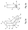
- the scraper 3 can be recognized as an individual part.
- the scraper 3 has an arranged at the angle B to the contact surface 15 base 12, which after assembly of the entire device at the pulley 6 facing tip has a planar shape with a radius R1, which can be considered infinitely large.
- the base 12 is formed as a groove with a decreasing radius. To illustrate this decreasing radius, the radii R2, R3 and R4 are shown by way of example. The connection of the lowest points of the channel is shown as a straight line S.
- the straight line S Due to the decreasing radius of the base 12, the straight line S, starting from the plane entrance side with the infinite radius R1 increases in the direction of the radius R4 at the exit side relative to the format base 1 in FIG. 1 at.
- the increasing distance of the Base area 12 of the format base 1 is realized in this embodiment by the increasing distance of the straight line S to the format base 1. Due to the increasing distance of the straight line S to the format base 1, the available cross-sectional area between the scraper 3 and the format base 1 is simultaneously increased.
- the tobacco rod 2 can thereby expand between the format base 1 and the scraper 3. In addition, it is possible to subsequently compress the tobacco rod-2 between the finger 4 and the format base 1 starting from a larger cross-sectional area.
- the radius of the base 12 in the transport direction T of the tobacco rod 2 may also be constant.
- the widening distance of the base 12 from the format base 1 is realized by the groove of constant radius, which forms the base 12, is arranged obliquely on the scraper 3.
- the gutter may e.g. extend with a constant depth in the base 12 or with an increasing depth in the base 12.
- FIG. 3 an embodiment of the invention can be seen in which in the transport direction T of the tobacco rod 2 in front of the guide roller 6 in addition an adjustable in the direction of arrow F guide shoe 16 is provided, against which the endless conveyor belt 5.
- the deflection roller 6 can be made invisible, and the distance x4 be effected solely by the adjustment of the guide shoe 16.
- the guide shoe 16 also has the task of further fixing the shape of the tobacco rod 2 with respect to the height and the relative position of the heads in the tobacco composite to the tobacco middle strand by guiding the tobacco rod 2 over a greater length of the transport path.
- an adjustable deflection roller 6 with an adjustable guide shoe 16 can be provided in combination, which results in a further improved guidance of the tobacco rod 2 and transfer of the tobacco rod 2 onto the format belt 10 or task of the tobacco rod 2 on the wrapping web 11 leaves.
Landscapes
- Manufacturing Of Cigar And Cigarette Tobacco (AREA)
Applications Claiming Priority (2)
| Application Number | Priority Date | Filing Date | Title |
|---|---|---|---|
| DE102010025548 | 2010-06-29 | ||
| DE201110100365 DE102011100365A1 (de) | 2010-06-29 | 2011-05-03 | Einrichtung zur Herstellung von stabförmigen Produkten der Tabak verarbeitenden Industrie |
Publications (2)
| Publication Number | Publication Date |
|---|---|
| EP2401928A2 true EP2401928A2 (fr) | 2012-01-04 |
| EP2401928A3 EP2401928A3 (fr) | 2014-10-01 |
Family
ID=44508575
Family Applications (1)
| Application Number | Title | Priority Date | Filing Date |
|---|---|---|---|
| EP11004862.6A Withdrawn EP2401928A3 (fr) | 2010-06-29 | 2011-06-15 | Dispositif de fabrication de produits en forme de tiges de l'industrie de traitement du tabac |
Country Status (3)
| Country | Link |
|---|---|
| EP (1) | EP2401928A3 (fr) |
| CN (1) | CN102326862A (fr) |
| DE (1) | DE102011100365A1 (fr) |
Cited By (1)
| Publication number | Priority date | Publication date | Assignee | Title |
|---|---|---|---|---|
| IT201700017823A1 (it) * | 2017-02-17 | 2018-08-17 | Gd Spa | Macchina per la produzione di almeno un baco continuo di materiale filtrante o tabacco. |
Families Citing this family (3)
| Publication number | Priority date | Publication date | Assignee | Title |
|---|---|---|---|---|
| RU2697045C2 (ru) | 2014-12-16 | 2019-08-08 | Филип Моррис Продактс С.А. | Литейная машина для производства литого полотна из гомогенизированного табачного материала |
| JP6665178B2 (ja) * | 2014-12-16 | 2020-03-13 | フィリップ・モーリス・プロダクツ・ソシエテ・アノニム | 均質化したたばこ材料のキャストウェブの製造のためのキャスティング装置 |
| CN115836743A (zh) * | 2022-12-01 | 2023-03-24 | 浙江中烟工业有限责任公司 | 一种卷烟机铲丝刀装置 |
Citations (1)
| Publication number | Priority date | Publication date | Assignee | Title |
|---|---|---|---|---|
| DE3407068A1 (de) | 1983-04-27 | 1984-10-31 | The Japan Tobacco & Salt Public Corp., Tokio/Tokyo | Zunge zur herstellung von zigarettenstaebchen |
Family Cites Families (14)
| Publication number | Priority date | Publication date | Assignee | Title |
|---|---|---|---|---|
| GB1578140A (en) * | 1976-07-14 | 1980-11-05 | Molins Ltd | Cigarette manufacture |
| DE3103056A1 (de) * | 1980-03-07 | 1982-02-04 | Hauni-Werke Körber & Co KG, 2050 Hamburg | Anordnung zum herstellen von zigaretten mit verstaerkten enden |
| US4605013A (en) * | 1983-02-02 | 1986-08-12 | Hauni-Werke Korber & Co. Kg | Method and apparatus for forming discrete batches of tobacco particles |
| IT1168681B (it) * | 1983-09-12 | 1987-05-20 | Gd Spa | Macchina confezionatrice di sigarette del tipo a baco continuo |
| DE3508497A1 (de) * | 1985-03-09 | 1986-09-11 | Hauni-Werke Körber & Co KG, 2050 Hamburg | Verfahren und vorrichtung zum bilden von tabakportionen, insbesondere fuer die herstellung eines aus aufeinanderfolgenden tabakabschnitten unterschiedlicher arten gebildeten tabakstranges |
| DE3701278A1 (de) * | 1986-01-30 | 1987-08-06 | Hauni Werke Koerber & Co Kg | Verfahren und maschine zum stopfen von huelsen fuer stabfoermige artikel der tabakverarbeitenden industrie |
| CH686334A5 (fr) * | 1991-01-31 | 1996-03-15 | Tabac Fab Reunies Sa | Machine à cigarettes. |
| DE4218258A1 (de) * | 1992-06-03 | 1993-12-09 | Decoufle Sarl | Formateinrichtung einer Zigarettenstrangmaschine |
| JP3248682B2 (ja) * | 1998-01-12 | 2002-01-21 | 日本たばこ産業株式会社 | シガレット製造機の刻みたばこ層圧縮成形装置 |
| DE19909216A1 (de) * | 1999-03-03 | 2000-09-07 | Hauni Maschinenbau Ag | Vorrichtung zum Aufbauen eines kontinuierlichen Tabakstranges |
| US7117871B2 (en) * | 2002-12-20 | 2006-10-10 | R.J. Reynolds Tobacco Company | Methods for manufacturing cigarettes |
| DE102004039325A1 (de) * | 2004-08-12 | 2006-02-23 | Hauni Maschinenbau Ag | Abgabe von Strangmaterial |
| DE102005021817A1 (de) * | 2005-05-04 | 2006-11-09 | Hauni Maschinenbau Ag | Gegenlage für ein oder jedes Trennelement eines Trennmittels sowie Vorrichtung zum Trennen von rauchbarem Material, wie z. B. Tabak, Tabakrippen, Tabakfolie und/oder Nelken von einem verdichteten Kuchen |
| DE102006045810B4 (de) * | 2006-09-26 | 2012-02-16 | Hauni Maschinenbau Ag | Saugstrangförderer und Verfahren zur Herstellung eines Strangs der Tabak verarbeitenden Industrie |
-
2011
- 2011-05-03 DE DE201110100365 patent/DE102011100365A1/de not_active Ceased
- 2011-06-15 EP EP11004862.6A patent/EP2401928A3/fr not_active Withdrawn
- 2011-06-28 CN CN2011101763177A patent/CN102326862A/zh active Pending
Patent Citations (1)
| Publication number | Priority date | Publication date | Assignee | Title |
|---|---|---|---|---|
| DE3407068A1 (de) | 1983-04-27 | 1984-10-31 | The Japan Tobacco & Salt Public Corp., Tokio/Tokyo | Zunge zur herstellung von zigarettenstaebchen |
Cited By (2)
| Publication number | Priority date | Publication date | Assignee | Title |
|---|---|---|---|---|
| IT201700017823A1 (it) * | 2017-02-17 | 2018-08-17 | Gd Spa | Macchina per la produzione di almeno un baco continuo di materiale filtrante o tabacco. |
| EP3363302A1 (fr) * | 2017-02-17 | 2018-08-22 | G.D. S.p.A | Machine pour la fabrication d'au moins une tige continue de matériau de filtre ou de tabac |
Also Published As
| Publication number | Publication date |
|---|---|
| EP2401928A3 (fr) | 2014-10-01 |
| CN102326862A (zh) | 2012-01-25 |
| DE102011100365A1 (de) | 2011-12-29 |
Similar Documents
| Publication | Publication Date | Title |
|---|---|---|
| EP1968757B1 (fr) | Procede et dispositif de fabrication d'elements de ressort cintres | |
| EP2521640B1 (fr) | Procédé et dispositif de fabrication d'un matériau composite fibreux sous la forme d'une bande de fibre imprégnée d'un polymère | |
| DE202016008856U1 (de) | Tiefziehverpackungsmaschine | |
| EP2401928A2 (fr) | Dispositif de fabrication de produits en forme de tiges de l'industrie de traitement du tabac | |
| EP0608861A2 (fr) | Procédé et dispositif pour alimenter des objets sensibles dans une machine de traitement | |
| EP3235388B1 (fr) | Dispositif d'application d'une bande de colle sur une bande d'enrobage en forme de tige de l'industrie de traitement du tabac | |
| EP2641483A1 (fr) | Dispositif de formatage d'une machine de fabrication de tiges | |
| EP2505269A2 (fr) | Dispositif destiné à l'encollage d'une bande d'enrobage mobile pour produits en forme de tige de l'industrie de traitement du tabac et installation dotée d'un tel dispositif | |
| EP4013246B1 (fr) | Fourniture de parties de bande métallique pour segments de tabac | |
| DE102014116270B3 (de) | Anlage und Verfahren zur kontinuierlichen Herstellung gekrümmter Preformen | |
| EP3144133A1 (fr) | Dispositif destine au rainurage de feuilles de materiau | |
| DE10035461B4 (de) | Verfahren und Vorrichtung zum Ausformen einer Süßwarenmasse | |
| EP1625797B1 (fr) | Distrbution de matériau filiforme | |
| DE2414262A1 (de) | Verfahren und vorrichtung zur streifenmontage von befestigungselementen | |
| EP2484232A2 (fr) | Machine de fabrication de tiges pour la fabrication de produits de l'industrie de traitement du tabac et garniture pour une machine de fabrication de tiges ainsi que procédé de fabrication de la garniture | |
| EP2713708B1 (fr) | Procédé pour façonner et faire refroidir une masse de fromage fondue préalablement chaude et par conséquent coulante | |
| EP2570206A1 (fr) | Machine à laminer des profilés | |
| EP4100243B1 (fr) | Machine de fabrication pour fabriquer des produits sous forme de tige à partir d'un brin sans fin d'un ruban collé en un tube | |
| EP3283263B1 (fr) | Dispositif de coupe avec un dispositif d'insertion d'un papier intercalaire | |
| EP2311329B1 (fr) | Transport d'articles en forme de tige de l'industrie de traitement du tabac | |
| EP1897454B1 (fr) | Agencement en forme de V d'ouvertures d'aspiration | |
| EP2756768B2 (fr) | Dispositif de guidage axial longitudinal de produits en forme de tiges de l'industrie de traitement du tabac | |
| DE10354797A1 (de) | Verfahren und Vorrichtung zur Herstellung eines umhüllungsmaterialstreifenfreien Filterstrangs der tabakverarbeitenden Industrie | |
| EP0814922B1 (fr) | Installation pour le sectionnement de plusieurs longueurs de fils dans un echeveau de fil | |
| DE102004055799B3 (de) | Verfahren zur Herstellung von Minen |
Legal Events
| Date | Code | Title | Description |
|---|---|---|---|
| AK | Designated contracting states |
Kind code of ref document: A2 Designated state(s): AL AT BE BG CH CY CZ DE DK EE ES FI FR GB GR HR HU IE IS IT LI LT LU LV MC MK MT NL NO PL PT RO RS SE SI SK SM TR |
|
| AX | Request for extension of the european patent |
Extension state: BA ME |
|
| PUAI | Public reference made under article 153(3) epc to a published international application that has entered the european phase |
Free format text: ORIGINAL CODE: 0009012 |
|
| PUAL | Search report despatched |
Free format text: ORIGINAL CODE: 0009013 |
|
| AK | Designated contracting states |
Kind code of ref document: A3 Designated state(s): AL AT BE BG CH CY CZ DE DK EE ES FI FR GB GR HR HU IE IS IT LI LT LU LV MC MK MT NL NO PL PT RO RS SE SI SK SM TR |
|
| AX | Request for extension of the european patent |
Extension state: BA ME |
|
| RIC1 | Information provided on ipc code assigned before grant |
Ipc: A24C 5/18 20060101AFI20140827BHEP |
|
| STAA | Information on the status of an ep patent application or granted ep patent |
Free format text: STATUS: THE APPLICATION IS DEEMED TO BE WITHDRAWN |
|
| 18D | Application deemed to be withdrawn |
Effective date: 20150106 |