EP2401928A2 - Device for producing rod-shaped articles from the tobacco processing industry - Google Patents
Device for producing rod-shaped articles from the tobacco processing industry Download PDFInfo
- Publication number
- EP2401928A2 EP2401928A2 EP11004862A EP11004862A EP2401928A2 EP 2401928 A2 EP2401928 A2 EP 2401928A2 EP 11004862 A EP11004862 A EP 11004862A EP 11004862 A EP11004862 A EP 11004862A EP 2401928 A2 EP2401928 A2 EP 2401928A2
- Authority
- EP
- European Patent Office
- Prior art keywords
- tobacco rod
- scraper
- base
- tobacco
- format
- Prior art date
- Legal status (The legal status is an assumption and is not a legal conclusion. Google has not performed a legal analysis and makes no representation as to the accuracy of the status listed.)
- Withdrawn
Links
Images

Classifications
-
- A—HUMAN NECESSITIES
- A24—TOBACCO; CIGARS; CIGARETTES; SIMULATED SMOKING DEVICES; SMOKERS' REQUISITES
- A24C—MACHINES FOR MAKING CIGARS OR CIGARETTES
- A24C5/00—Making cigarettes; Making tipping materials for, or attaching filters or mouthpieces to, cigars or cigarettes
- A24C5/14—Machines of the continuous-rod type
- A24C5/18—Forming the rod
- A24C5/1807—Forming the rod with compressing means, e.g. garniture
Definitions
- the invention relates to a device for the production of rod-shaped products of the tobacco processing industry having the features of the preamble of claim 1 and a scraper for such a device having the features of one of the preambles of claim 9 or 11.
- Rod-shaped products of the tobacco processing industry are e.g. Cigarettes or cigarillos, which are produced by machine from a continuously fed tobacco rod, which is placed on an equally continuously supplied wrapping web and is then fixed by laying the wrapping web around the tobacco rod to a rod-shaped strand. The rod-shaped products are then cut in a predetermined length of the strand.
- the tobacco is first sucked in the device by means of a negative pressure, porous, endless conveyor belt from a supply or a homogenization chamber and conveyed to a trimming device.
- the trimming device is formed by one or two rotating cutting disks located at a constant distance from the conveyor belt, which can have, for example, depressions distributed regularly over the circumference.
- the cutting wheels are aligned with the conveyor belt so that they separate the tobacco rod during rotation from the adhering to the conveyor belt tobacco mass at a predetermined height.
- the recesses in the cutting discs have it the task of creating regularly spaced portions with a larger cross-section in the tobacco rod, which form the heads of the tobacco rod in the finished product after the completion of the rod-shaped products.
- the free end or free ends of the tobacco rod designates the filter-facing end of the tobacco rod in the finished product. If cut-off wheels without depressions are used, the sections with the enlarged cross-sections are provided by means provided on the side of the tobacco rod for changing the geometry of the tobacco rod.
- the tobacco rod After passing through the trimming device, the tobacco rod has a non-round, preferably rectangular cross-section and is separated from the conveyor belt by a scraper for release from the conveyor belt on a deflection roller. Due to the concerns of the conveyor belt on the pulley this is no longer acted upon by the vacuum, so that the force acting on the tobacco rod holding force decreases and finally no longer exists. As a result, the tobacco rod already dissolves itself from the conveyor belt and is then continued by the scraper. Nevertheless, the scraper should be arranged as close as possible to the deflection roller, without touching the conveyor belt, so that the movement of the tobacco strand in the further course of the conveyor belt is guided on a transported from a format tape wrapping, and to free the conveyor belt of dirt.
- the tobacco rod separated from the conveyor belt is placed on a continuously supplied wrapping web, which is placed around the tobacco rod and glued together at their lateral edges.
- the wrapping web is placed on a further transport movement effecting format tape, which is guided on a format background with a profiled surface.
- the surface of the format base is profiled in such a way that the edge of the wrapping web is pushed up laterally of the tobacco rod, so that the tobacco rod is prefixed in the formed groove, and at one of the edges a glue trace enabling the subsequent bonding can be applied.
- the scraper next to the separation of the tobacco rod has the additional task to convert the cross-section not round tobacco rod at the top at least in a preform with a part-circular cross-section and has to a transition from a flat surface in a curved surface surface.
- a finger In the transport direction behind the scraper is directly followed by a finger, which completes the shaping of the top of the tobacco rod to a circle segment before the shape of the tobacco rod is fixed by the wrapping and gluing of the wrapping web.
- the scraper and the finger can be formed in one piece, with a separate embodiment has the advantage that the scraper and the finger can be replaced separately as wearing parts.
- the tobacco rod of the rectangular or non-round cross-sectional shape having a first cross-sectional area and regular portions having a larger second cross-sectional area is converted into a rod-shaped form having a constant diameter.
- the tobacco rod is at least partially compressed, in which case the sections with the larger cross-sectional area, so the heads are compressed more. This higher compression can be done in the worst case Incorrect settings lead to a tearing of the tobacco rod by the higher contact pressure or to shift the relative position of the heads in the tobacco rod.
- the continuous manufacturing process In the event that the tobacco rod breaks or builds up, the continuous manufacturing process must be stopped, the device stopped and the tobacco rod guide path cleaned before restarting the device.
- the relative position of the heads in the tobacco rod is not changed by the compression, and that the heads after production have a predetermined density, so that the so-called head failure does not exceed a predetermined amount of tobacco.
- the length of the heads in the finished products also does not correspond to the predetermined length, so that the predetermined limit for the head failure can be exceeded.
- head failure is understood to mean the amount of tobacco particles which falls out of the end of the product not covered by a filter in the further production process up to the final packaging.
- the predetermined, not to be exceeded head loss is a decisive quality criterion for the product itself, which is required by the manufacturer of the products. Excessive head failure can also lead to disturbances in the subsequent processing of the products by the falling out tobacco particles pollute functional areas of the device.
- the scraper and the finger are subject to a variety of requirements for the above reasons and are for the maintenance of quality criteria and trouble-free continuous operation of the device very important items that must be checked at regular intervals and replaced if necessary.
- a generic device is for example from the DE 34 07 068 A1 in which a scraper designated there as a compression shoe is provided, to which a finger designated there as a tongue part connects.
- the finger has a contact surface converging in the direction of the transport direction of the tobacco rod to a base surface with a plurality of frusto-conical sections.
- the frusto-conical sections are intended to prevent excessive heating of the finger and the consequent adherence of tar.
- the shape of the scraper is not described in detail; however, it is believed that the shape of the scraper is also converging since it was called a "compression shoe".
- the object of the invention is to provide a device with which a production of rod-shaped products of the tobacco-processing industry with a reliably below a limit remaining head loss is possible.
- a device for the production of rod-shaped products of the tobacco-processing industry with a conveyor for continuously feeding a tobacco rod with a first cross-sectional area, which has sections with a larger second cross-sectional area at regular intervals, wherein the conveyor by a guided over a pulley Continuous conveyor belt is formed, on which the tobacco rod is arranged, and a run on a format basis format tape on which a continuously fed wrapping web, and a tobacco rod of the endless conveyor belt separating scraper, which has such a profiled base, the non-circular in cross-section tobacco rod is deformed when passing on the base to a tobacco rod with a curved outer surface proposed, in which the distance between the base and the Format ground in the transport direction of the T abakstranges increases, in the transport direction of the tobacco rod behind the scraper, a finger is provided, which has a contact surface, and the base and the contact surface without a gap merge into each other.
- the term of the base of the scraper is to be understood as the area in which the lowest points of the profiled surface are arranged. If the scraper has a profiled surface that merges into a groove from a plane, the base area of the scraper would be the surface in which first the plane surface of the scraper is located on the inlet side of the tobacco rod and in the further course the lowest points of the groove. If no such area is definable, the base area is the average area between the lowest points.
- the base of the scraper in the transport direction of the tobacco rod is basically aligned either parallel to the format base or converging to this.
- Such a solution initially seems to make sense, since the tobacco rod must be pressed into the ultimately rod-shaped mold with a constant diameter.
- the proposed solution according to the invention deviates from this principle and suggests that the distance should increase, so that the base is arranged diverging to the format reason.
- This allows an initially seemingly unrealistic widening of the tobacco rod.
- This widening of the tobacco rod prevents the tobacco rod is compressed in particular in the region of the heads over a longer portion of the transport path so far that changes the relative position of the heads in the tobacco rod, in particular their location in the tobacco composite to tobacco rod.
- the deviations in the length of the heads in the product are also less, which can further reduce head loss. Furthermore, the frictional forces are reduced by the inventive solution, so that the scraper heats itself less. Due to the gap-free merging base and contact surface of the tobacco rod is passed directly to the contact surface after the brief expansion of the base in the transport direction of the tobacco rod, so that the shape of the tobacco rod at the contact surface directly adjoins the expansion of the base, without the tobacco rod can deform or expand in an intermediate phase uncontrolled.
- the term "gap-free" refers to an immediate within the meaning of the invention Connection of the contact surface in the transport direction of the tobacco rod to the base.
- the base surface is arranged at an angle of 0.5 to 6.0 degrees, preferably from 2.0 to 4.5 degrees to the format base.
- the proposed angular ranges have been found to be advantageous in a number of test series with different types of tobacco, wherein it is particularly important that the tobacco distribution predetermined by the trimming device when separating the tobacco rod from the tobacco volume and the subsequently resulting density distribution of the tobacco rod are not lost in the further processing process goes.
- the distance between the contact surface and the format base decreases in the transport direction of the tobacco rod.
- the finger has the task to shape the top of the voltage applied to the contact surface tobacco rod to a circular segment with a predetermined radius. Because of the inventively proposed increasing distance between the format base and the base of the scraper and the decreasing distance between the contact surface of the finger and the format base, the first by the shape of the base expanded tobacco rod can be deformed at the contact surface of the finger with a much greater degree of deformation, than is possible with the solutions known in the art.
- the scraper and the finger can preferably be formed in one piece, whereby a much more accurate arrangement of the base to the contact surface of the finger can be realized because the tolerance chain is at least shortened by the one-piece arrangement.
- the distance between the contact surface on the side of the finger at which the tobacco rod emerges and the format base corresponds to the diameter of the finished rod-shaped product minus 0.6 - 1.5 mm.
- the proposed distance has also proved to be ideal, especially with regard to the proposed geometry of the doctor, for a continuous and trouble-free production of the rod-shaped products.
- a trimming device which is formed by one or more cutting discs, by means of which the tobacco rod can be separated from a tobacco volume, and the distance between the cutting discs and the endless conveyor belt and the distance between the last in the transport direction of the tobacco rod pulley, on which the endless conveyor belt rests, and the format reason minus the thickness of the conveyor belt applied to the deflection roller, the thickness of a wrapping web on which the tobacco rod rests, and the thickness of a resting on the format base format strip within a tolerance of +/- 0.5 mm are identical.
- the scraper and / or the finger is or are formed from a thick-walled component without cavities, at least in the area of the base area and / or the area of the contact surface.
- the proposed solution allows a very precise component processing and also a high dimensional stability of the scraper and the finger even after a longer higher mechanical and thermal stress.
- the distance of the deflection roller to the format base thus simultaneously corresponds to the height which defines the first cross-sectional area of the tobacco rod. Due to the distance between the last in the transport direction of the tobacco strand pulley and the format reason is determined at the same time, with which pressing force of the tobacco rod is pressed onto the wrapping path located on the format tape.
- the deflection roller defines a transfer point, from which the tobacco rod is transported for further transport on the wrapping web of the format tape. For this reason, it is of particular importance for trouble-free operation of the device that the tobacco rod is transported continuously through the device at the transfer point.
- the proposed distance of the pulley has been found in this regard to be ideal for the transport conditions, since the tobacco rod is thereby pressed for its trouble-free transfer with a sufficient contact pressure on the wrapping, without causing the risk of tearing or damming the tobacco rod.
- the proposed distance of the deflection roller from the format base the transport of the tobacco rod can be improved regardless of the shape and orientation of the scraper.
- a scraper for a device for producing rod-shaped products of the tobacco processing industry for separating a continuously fed tobacco rod from an endless conveyor belt which has a contact surface for abutment with the device and a base surface at which the tobacco rod comes to rest, and Angle between the contact surface and the base surface is greater than 90 degrees.
- the advantage of the proposed scraper is the fact that the scraper is designed so that the inventive Advantage is made possible by the alignment of the base alone by the scraper itself. All that is required is a contact surface, which is oriented perpendicular to the format base, on the device on which the scraper can be arranged. The angle of the base to the tobacco rod or to the format reason is then automatically given by the angle of the base to the contact surface. In particular, this makes it possible to realize different angles individually in a standard machine according to the customer requirements or depending on the type of tobacco to be processed by the scraper is replaced and replaced by a scraper with a different angle between the base and the contact surface.
- the angle between the base surface and the contact surface should be 90.5 to 96.0 degrees, preferably 92 to 94.5 degrees.
- a scraper for a device for the production of rod-shaped products of the tobacco-processing industry for separating a continuously fed tobacco rod is proposed by an endless conveyor belt, which in the mounting position of the scraper to the perpendicular skewed contact surface for abutment with the device, and a Base area, where the tobacco rod comes to rest, and the angle between the contact surface and the base surface is less than 90 degrees, and the sum of the angle between the contact surface and the vertical and the angle between the contact surface and the base greater than 90 Degree is.
- the proposed scraper allows the same inventive success as the scraper proposed according to claim 7, with the difference that the proposed scraper can also be arranged on a perpendicular to the vertical oblique contact surface of the device.
- a finger is integrally formed on the inventively proposed scrapers. Due to the one-piece design of the scraper and the finger, these can be exchanged together in one step. In addition, the tolerance chain is shortened by the no longer existing contact surface by a degree, so that the base and the contact surface of the finger can be realized with a much higher accuracy to each other.
- FIG. 1 a device according to the invention can be seen, in which a disordered tobacco volume 7 homogenized in an upstream homogenizing device is sucked by means of negative pressure from a porous endless conveyor belt 5.
- a weight control shoe 9 On one side of the endless conveyor belt 5 is a weight control shoe 9, which is movable in the direction of arrow C.
- a trimmer 14 On the opposite side of the endless conveyor belt 5 is a trimmer 14 in the form of one or more rotating Cutting discs each provided with one or more recesses 8. The distance between the endless conveyor belt 5 and the trimming device 14 can be changed by moving the weight control shoe 9 in the direction of arrow C.
- the endless conveyor belt 5 wraps around in the course of a deflection roller 6 and is driven by a drive device, not shown, to move in the direction of arrow D.
- the adhering tobacco volume 7 is pulled in the direction of the trimming device 14 and thereby cut by the rotating cutting discs to a tobacco rod 2.
- the tobacco rod 2 after cutting has a first cross-sectional area defined by the first height x1 and regular portions 2a having a larger cross-sectional area defined by the one second height x2.
- the first height x1 is predetermined by the set distance between the cutting wheel and the endless conveyor belt 5, while the second height x2 is predetermined by the first height x1 plus the dimension of the recess 8.
- the first height x1 and the second height x2 are therefore directly related due to the unalterable dimension of the recess 8.
- the sections 2a with the greater height x2 form the heads of the tobacco rod 2 located in the product after the production of the rod-shaped products.
- the tobacco rod 2 to the transport direction T of the tobacco rod 2 last pulley 6, at which the endless conveyor belt 5 is applied, and runs on a continuously supplied, wrapping web 11.
- the wrapping web 11 is guided by a in the transport direction T driven format tape 10, which in turn rests on a Formatground 1.
- the Formatground 1 forms a support surface and is corresponding to the rod-shaped product to be formed with a groove with a continuous provided in decreasing radius, in which the format strip 10 is guided with the wrapping web 11 and the tobacco rod 2 laid thereon.
- the deflection roller 6 is aligned at a distance x3 to the format base 1, which minus the thickness of the endless conveyor belt 5, the thickness of the wrapping web 11 and the thickness of the format strip 10 of the first height x1 of the tobacco rod 2 within a tolerance of +/- 0.5 mm corresponds.
- the proposed distance of the deflection roller 6 to the format base 1 has been found to be ideal for the further continuous transport of the tobacco rod 2.
- the scraper 3 is provided with a base 12 which is shaped such that the distance between the base 12 and the format base 1 in the transport direction T of the tobacco rod 2 increases.
- the increase of the distance is in the presentation represented as angle A greater than 0 degrees.
- the scraper 3 is further provided with an aligned in the mounting position perpendicular to the format base 1 contact surface 15, so that the increasing distance between the base 12 and the format reason 1 by the angle B between the base 12 and the contact surface 15 of preferably 90th , 5 to 96 degrees and in particular from 92 to 94.5 degrees.
- the angle A can be changed particularly easily by the use of a scraper 3 with a different angle B.
- the contact surface 15 of the scraper 3 is in the attachment position in contact with a likewise perpendicular to the format base 1 aligned contact surface of a finger 4, which is arranged in the transport direction T of the tobacco rod 2 behind the scraper 3.
- the finger 4 is provided on its side facing the format base 1 with a contact surface 14, which is shaped such that the distance between the contact surface 14 and the format base 1 decreases in the transport direction T.
- a step, formed by a material surplus of the base surface 12 is expediently provided, which represents a wear reserve and prevents the tobacco rod 2 from starting with the surface against an edge of the contact surface 14.
- the angle B can also be chosen smaller than 90 degrees, in which case the sum of the angle between the contact surface 15 and the vertical and the angle B larger than 90 degrees should be to bring about the success of the invention.
- the finger 4 is arranged directly on the scraper 3, so that there is no gap between the two parts in the transport direction T of the tobacco rod.
- the base 12 is thereby in the transport direction T directly into the contact surface 14 via. Since the scraper 3 and the finger 4 are each designed as thick-walled components without cavities, they can be made very accurately from a solid material. As a manufacturing process to offer all metal cutting processes and erosion. Furthermore, the components can be dimensioned such that the base surface 12 and contact surface 14 arranged thereon have a high dimensional accuracy even with high mechanical and thermal stress.
- the shape of the tobacco rod 2 takes place on the one hand by the channel located in the format 1 and on the other hand by the profiled base 12 of the scraper and the contact surface 14 of the finger 4. Since the distance between the base 12 and the format base 1 increases in the transport direction T, can the tobacco rod 2 at least slightly widen after the short-term compression in the narrowest cross-section. Due to the mere momentary compression of the tobacco rod 2 in the narrowest cross-section, it is ensured that the relative position of the heads, i. H. the sections 2a, is not changed in the tobacco composite to the tobacco middle strand.
- the tobacco rod strand is the main body of the tobacco rod 2, which is formed by the sections with the first height x1.
- the tobacco rod 2 can be deformed after the passage from the base 12 of a larger cross-sectional area at the inlet side of the finger 4 to a much smaller cross-sectional area with a significantly greater degree of deformation than was possible with the known in the prior art solutions.
- the actual shaping of the tobacco rod 2 therefore takes place between the contact surface 14 and the format base 1.
- the distance y between the contact surface 14 on the outlet side of the tobacco rod 2 and the Format strip 10 corresponds approximately to the diameter of the finished product minus 0.6 to 1.5 mm.
- the finger 4 is executed in the described embodiment as a separate item, but it can also be integrally formed on the scraper 3, whereby the number of parts can be reduced.
- the tobacco rod 2 can be formed much more reliable process to a desired shape with a desired density distribution by the proposed solution between the contact surface 14 and the format reason 1, since the deformation of the tobacco rod 2 starts with a larger cross-sectional area. Thereby, the target density and target position of the heads in the tobacco rod 2 can be maintained much more accurately, and it is prevented that the unavoidable head failure exceeds a predetermined limit.
- the scraper 3 can be recognized as an individual part.
- the scraper 3 has an arranged at the angle B to the contact surface 15 base 12, which after assembly of the entire device at the pulley 6 facing tip has a planar shape with a radius R1, which can be considered infinitely large.
- the base 12 is formed as a groove with a decreasing radius. To illustrate this decreasing radius, the radii R2, R3 and R4 are shown by way of example. The connection of the lowest points of the channel is shown as a straight line S.
- the straight line S Due to the decreasing radius of the base 12, the straight line S, starting from the plane entrance side with the infinite radius R1 increases in the direction of the radius R4 at the exit side relative to the format base 1 in FIG. 1 at.
- the increasing distance of the Base area 12 of the format base 1 is realized in this embodiment by the increasing distance of the straight line S to the format base 1. Due to the increasing distance of the straight line S to the format base 1, the available cross-sectional area between the scraper 3 and the format base 1 is simultaneously increased.
- the tobacco rod 2 can thereby expand between the format base 1 and the scraper 3. In addition, it is possible to subsequently compress the tobacco rod-2 between the finger 4 and the format base 1 starting from a larger cross-sectional area.
- the radius of the base 12 in the transport direction T of the tobacco rod 2 may also be constant.
- the widening distance of the base 12 from the format base 1 is realized by the groove of constant radius, which forms the base 12, is arranged obliquely on the scraper 3.
- the gutter may e.g. extend with a constant depth in the base 12 or with an increasing depth in the base 12.
- FIG. 3 an embodiment of the invention can be seen in which in the transport direction T of the tobacco rod 2 in front of the guide roller 6 in addition an adjustable in the direction of arrow F guide shoe 16 is provided, against which the endless conveyor belt 5.
- the deflection roller 6 can be made invisible, and the distance x4 be effected solely by the adjustment of the guide shoe 16.
- the guide shoe 16 also has the task of further fixing the shape of the tobacco rod 2 with respect to the height and the relative position of the heads in the tobacco composite to the tobacco middle strand by guiding the tobacco rod 2 over a greater length of the transport path.
- an adjustable deflection roller 6 with an adjustable guide shoe 16 can be provided in combination, which results in a further improved guidance of the tobacco rod 2 and transfer of the tobacco rod 2 onto the format belt 10 or task of the tobacco rod 2 on the wrapping web 11 leaves.
Landscapes
- Manufacturing Of Cigar And Cigarette Tobacco (AREA)
Abstract
Description
Die Erfindung betrifft eine Einrichtung zur Herstellung von stabförmigen Produkten der Tabak verarbeitenden Industrie mit den Merkmalen des Oberbegriffs von Anspruch 1 sowie einen Schaber für eine derartige Einrichtung mit den Merkmalen von einem der Oberbegriffe von Anspruch 9 oder 11.The invention relates to a device for the production of rod-shaped products of the tobacco processing industry having the features of the preamble of claim 1 and a scraper for such a device having the features of one of the preambles of
Stabförmige Produkte der Tabak verarbeitenden Industrie im Sinne der Erfindung sind z.B. Zigaretten oder Zigarillos, welche maschinell aus einem kontinuierlich zugeführten Tabakstrang hergestellt werden, der auf eine ebenso kontinuierlich zugeführte Hüllbahn gelegt wird und anschließend durch Herumlegen der Hüllbahn um den Tabakstrang zu einem stabförmigen Strang fixiert wird. Die stabförmigen Produkte werden dann in einer vorbestimmten Länge von dem Strang abgeschnitten.Rod-shaped products of the tobacco processing industry according to the invention are e.g. Cigarettes or cigarillos, which are produced by machine from a continuously fed tobacco rod, which is placed on an equally continuously supplied wrapping web and is then fixed by laying the wrapping web around the tobacco rod to a rod-shaped strand. The rod-shaped products are then cut in a predetermined length of the strand.
Zur Herstellung des Tabakstranges wird der Tabak in der Einrichtung zunächst mittels eines mit Unterdruck beaufschlagten, porösen, endlosen Förderbandes aus einem Vorrat bzw. einer Vergleichmäßigungskammer angesaugt und zu einer Trimmeinrichtung befördert. Die Trimmeinrichtung ist durch eine oder zwei in einem konstanten Abstand zu dem Förderband befindliche rotierende Trennscheiben gebildet, welche z.B. über den Umfang regelmäßig verteilte Vertiefungen aufweisen können. Die Trennscheiben sind derart zu dem Förderband ausgerichtet, dass sie den Tabakstrang während der Rotationsbewegung aus der an dem Förderband anhaftenden Tabakmasse in einer vorbestimmten Höhe abtrennen. Die Vertiefungen in den Trennscheiben haben dabei die Aufgabe, regelmäßig beabstandete Abschnitte mit einem größeren Querschnitt in dem Tabakstrang zu schaffen, welche nach der Fertigstellung der stabförmigen Produkte die Köpfe des Tabakstranges in dem fertigen Produkt bilden. Als Köpfe werden das freie Ende bzw. die freien Enden des Tabakstranges oder soweit das Produkt einen Filter aufweist, das dem Filter zugewandte Ende des Tabakstranges in dem fertigen Produkt bezeichnet. Sofern Trennscheiben ohne Vertiefungen verwendet werden, werden die Abschnitte mit den vergrößerten Querschnitten durch seitlich des Tabakstranges vorgesehene Mittel zur Veränderung der Geometrie des Tabakstranges geschaffen.To produce the tobacco rod, the tobacco is first sucked in the device by means of a negative pressure, porous, endless conveyor belt from a supply or a homogenization chamber and conveyed to a trimming device. The trimming device is formed by one or two rotating cutting disks located at a constant distance from the conveyor belt, which can have, for example, depressions distributed regularly over the circumference. The cutting wheels are aligned with the conveyor belt so that they separate the tobacco rod during rotation from the adhering to the conveyor belt tobacco mass at a predetermined height. The recesses in the cutting discs have it the task of creating regularly spaced portions with a larger cross-section in the tobacco rod, which form the heads of the tobacco rod in the finished product after the completion of the rod-shaped products. As heads, the free end or free ends of the tobacco rod, or as far as the product has a filter, designates the filter-facing end of the tobacco rod in the finished product. If cut-off wheels without depressions are used, the sections with the enlarged cross-sections are provided by means provided on the side of the tobacco rod for changing the geometry of the tobacco rod.
Der Tabakstrang weist nach dem Durchlauf durch die Trimmeinrichtung einen nicht runden, vorzugsweise rechteckförmigen Querschnitt auf und wird zum Lösen von dem Förderband an einer Umlenkrolle mittels eines Schabers von dem Förderband getrennt. Durch das Anliegen des Förderbandes an der Umlenkrolle wird dieses nicht mehr durch das Vakuum beaufschlagt, so dass die auf den Tabakstrang wirkende Haltekraft abnimmt und schließlich nicht mehr vorhanden ist. Dadurch löst sich der Tabakstrang bereits selbst von dem Förderband und wird durch den Schaber anschließend weitergeführt. Dennoch sollte der Schaber möglichst dicht an der Umlenkrolle angeordnet sein, ohne das Förderband dabei zu berühren, damit die Bewegung des Tabakstranges im weiteren Verlauf von dem Förderband auf eine von einem Formatband transportierte Hüllbahn geführt erfolgt, und um das Förderband von Verschmutzungen zu befreien.After passing through the trimming device, the tobacco rod has a non-round, preferably rectangular cross-section and is separated from the conveyor belt by a scraper for release from the conveyor belt on a deflection roller. Due to the concerns of the conveyor belt on the pulley this is no longer acted upon by the vacuum, so that the force acting on the tobacco rod holding force decreases and finally no longer exists. As a result, the tobacco rod already dissolves itself from the conveyor belt and is then continued by the scraper. Nevertheless, the scraper should be arranged as close as possible to the deflection roller, without touching the conveyor belt, so that the movement of the tobacco strand in the further course of the conveyor belt is guided on a transported from a format tape wrapping, and to free the conveyor belt of dirt.
Im weiteren Verlauf wird der von dem Förderband getrennte Tabakstrang auf eine kontinuierlich zugeführte Hüllbahn gelegt, welche um den Tabakstrang herumgelegt und an ihren seitlichen Rändern miteinander verklebt wird. Die Hüllbahn wird dazu auf ein die weitere Transportbewegung bewirkendes Formatband gelegt, welches auf einem Formatgrund mit einer profilierten Oberfläche geführt ist. Die Oberfläche des Formatgrundes ist dabei derart profiliert, dass der Rand der Hüllbahn seitlich des Tabakstranges hochgeschlagen wird, so dass der Tabakstrang in der gebildeten Rinne vorfixiert ist, und an einem der Ränder eine die anschließende Verklebung ermöglichende Leimspur aufgetragen werden kann.In the further course of the tobacco rod separated from the conveyor belt is placed on a continuously supplied wrapping web, which is placed around the tobacco rod and glued together at their lateral edges. The wrapping web is placed on a further transport movement effecting format tape, which is guided on a format background with a profiled surface. The surface of the format base is profiled in such a way that the edge of the wrapping web is pushed up laterally of the tobacco rod, so that the tobacco rod is prefixed in the formed groove, and at one of the edges a glue trace enabling the subsequent bonding can be applied.
Der Schaber hat neben dem Abtrennen des Tabakstranges die zusätzliche Aufgabe, den im Querschnitt nicht runden Tabakstrang an der Oberseite zumindest in eine Vorform mit einem teilkreisförmigen Querschnitt zu überführen und weist dazu eine aus einer ebenen Fläche in eine gekrümmte Fläche übergehende Grundfläche auf. In Transportrichtung hinter dem Schaber schließt sich direkt ein Finger an, welcher die Formgebung der Oberseite des Tabakstranges zu einem Kreissegment vollendet, bevor die Form des Tabakstranges durch das Herumschlagen und Verkleben der Hüllbahn fixiert wird.The scraper next to the separation of the tobacco rod has the additional task to convert the cross-section not round tobacco rod at the top at least in a preform with a part-circular cross-section and has to a transition from a flat surface in a curved surface surface. In the transport direction behind the scraper is directly followed by a finger, which completes the shaping of the top of the tobacco rod to a circle segment before the shape of the tobacco rod is fixed by the wrapping and gluing of the wrapping web.
Der Schaber und der Finger können dabei einstückig ausgebildet sein, wobei eine getrennte Ausführung den Vorteil hat, dass der Schaber und der Finger als Verschleißteile separat ausgetauscht werden können.The scraper and the finger can be formed in one piece, with a separate embodiment has the advantage that the scraper and the finger can be replaced separately as wearing parts.
Während der beschriebenen Formgebung des Tabakstranges wird der Tabakstrang aus der rechteckigen oder nicht runden Querschnittsform mit einer ersten Querschnittsfläche und regelmäßigen Abschnitten mit einer größeren zweiten Querschnittsfläche in eine stabförmige Form mit einem konstanten Durchmesser überführt. Dabei wird der Tabakstrang zumindest abschnittsweise komprimiert, wobei dabei die Abschnitte mit der größeren Querschnittsfläche, also die Köpfe stärker komprimiert werden. Diese höhere Kompression kann im schlechtesten Fall durch Fehleinstellungen zu einem Abreißen des Tabakstranges durch die höhere Anpresskraft oder zu einem Verschieben der relativen Lage der Köpfe in dem Tabakstrang führen.During the described shaping of the tobacco rod, the tobacco rod of the rectangular or non-round cross-sectional shape having a first cross-sectional area and regular portions having a larger second cross-sectional area is converted into a rod-shaped form having a constant diameter. In this case, the tobacco rod is at least partially compressed, in which case the sections with the larger cross-sectional area, so the heads are compressed more. This higher compression can be done in the worst case Incorrect settings lead to a tearing of the tobacco rod by the higher contact pressure or to shift the relative position of the heads in the tobacco rod.
Für den Fall, dass der Tabakstrang abreißt oder aufstaut, muss der kontinuierliche Herstellungsprozess unterbrochen werden, die Einrichtung angehalten und der Führungsweg des Tabakstranges vor einem Neustart der Einrichtung gereinigt werden.In the event that the tobacco rod breaks or builds up, the continuous manufacturing process must be stopped, the device stopped and the tobacco rod guide path cleaned before restarting the device.
Wichtig für die Qualität der fertigen Produkte ist ferner, dass die relative Lage der Köpfe in dem Tabakstrang durch die Kompression nicht verändert wird, und dass die Köpfe nach der Herstellung eine vorbestimmte Dichte aufweisen, damit der sogenannte Kopfausfall eine vorbestimmte Menge an Tabak nicht überschreitet. Für den Fall, dass die relative Lage der Köpfe von der vorbestimmten Lage abweicht, entspricht die Länge der Köpfe in den fertigen Produkten ebenfalls nicht der vorbestimmten Länge, so dass der vorgegebene Grenzwert für den Kopfausfall überschritten werden kann. Unter dem Begriff Kopfausfall wird die Menge an Tabakpartikeln verstanden, welche aus der nicht durch einen Filter abgedeckten Stirnseite des Produktes im weiteren Produktionsprozess bis zur Endverpackung heraus fällt. Der vorgegebene, nicht zu überschreitende Kopfausfall ist ein entscheidendes Qualitätskriterium für das Produkt selber, welches von Seiten des Herstellers der Produkte gefordert wird. Ein zu hoher Kopfausfall kann außerdem zu Störungen in dem nachfolgenden Weiterverarbeitungsprozess der Produkte führen, indem die heraus fallenden Tabakpartikel funktionswichtige Bereiche der Einrichtung verschmutzen.It is also important for the quality of the finished products that the relative position of the heads in the tobacco rod is not changed by the compression, and that the heads after production have a predetermined density, so that the so-called head failure does not exceed a predetermined amount of tobacco. In the event that the relative position of the heads deviates from the predetermined position, the length of the heads in the finished products also does not correspond to the predetermined length, so that the predetermined limit for the head failure can be exceeded. The term head failure is understood to mean the amount of tobacco particles which falls out of the end of the product not covered by a filter in the further production process up to the final packaging. The predetermined, not to be exceeded head loss is a decisive quality criterion for the product itself, which is required by the manufacturer of the products. Excessive head failure can also lead to disturbances in the subsequent processing of the products by the falling out tobacco particles pollute functional areas of the device.
Ein weiteres Problem solcher Einrichtungen besteht darin, dass der Tabakstrang mit einer hohen Geschwindigkeit geführt wird, so dass sich sowohl der Schaber als auch der Finger erwärmen und eventuell in dem Tabak enthaltene Bestandteile an deren Oberfläche anhaften und dadurch eine kontinuierliche Führung des Tabakstranges stören können.Another problem with such devices is that the tobacco rod is guided at a high speed, so that both the scraper and the finger heat up and possibly contained in the tobacco components adhere to the surface and thereby disturb a continuous guidance of the tobacco rod.
Der Schaber und der Finger unterliegen aus den vorgenannten Gründen einer Vielzahl von Anforderungen und sind für die Einhaltung der Qualitätskriterien und einen störungsfreien Dauerbetrieb der Einrichtung sehr wichtige Einzelteile, welche in regelmäßigen Abständen überprüft und gegebenenfalls ausgetauscht werden müssen.The scraper and the finger are subject to a variety of requirements for the above reasons and are for the maintenance of quality criteria and trouble-free continuous operation of the device very important items that must be checked at regular intervals and replaced if necessary.
Eine gattungsgemäße Einrichtung ist zum Beispiel aus der
Aufgabe der Erfindung ist es, eine Einrichtung zu schaffen, mit der eine Herstellung von stabförmigen Produkten der Tabak verarbeitenden Industrie mit einem zuverlässig unterhalb eines Grenzwertes bleibenden Kopfausfalls möglich ist.The object of the invention is to provide a device with which a production of rod-shaped products of the tobacco-processing industry with a reliably below a limit remaining head loss is possible.
Die Aufgabe wird erfindungsgemäß durch eine Einrichtung mit den Merkmalen von Anspruch 1 und einen Schaber für eine derartige Einrichtung mit den Merkmalen von Anspruch 9 oder 11 gelöst. Weitere bevorzugte Ausführungsformen der Erfindung sind den Unteransprüchen, den Figuren und der zugehörigen Beschreibung zu entnehmen.The object is achieved by a device having the features of claim 1 and a scraper for such a device with the features of
Zur Lösung der Aufgabe wird eine Einrichtung zur Herstellung von stabförmigen Produkten der Tabak verarbeitenden Industrie mit einer Fördereinrichtung zur kontinuierlichen zuführung eines Tabakstranges mit einer ersten Querschnittsfläche, welcher in regelmäßigen Abständen Abschnitte mit einer größeren zweiten Querschnittsfläche aufweist, wobei die Fördereinrichtung durch ein über eine Umlenkrolle geführtes Endlosförderband gebildet ist, an dem der Tabakstrang angeordnet ist, und einem auf einem Formatgrund geführten Formatband, auf dem eine kontinuierlich zugeführte Hüllbahn aufliegt, und einem den Tabakstrang von dem Endlosförderband trennenden Schaber, welcher eine derartig profilierte Grundfläche aufweist, das der im Querschnitt unrunde Tabakstrang beim Vorbeiführen an der Grundfläche zu einem Tabakstrang mit einer gekrümmten Außenfläche verformt wird, vorgeschlagen, bei der der Abstand zwischen der Grundfläche und dem Formatgrund in Transportrichtung des Tabakstranges zunimmt, in Transportrichtung des Tabakstranges hinter dem Schaber ein Finger vorgesehen ist, welcher eine Anpressfläche aufweist, und die Grundfläche und die Anpressfläche spaltfrei ineinander übergehen. Unter dem Begriff der Grundfläche des Schabers ist dabei die Fläche zu verstehen, in der die tiefsten Punkte der profilierten Oberfläche angeordnet sind. Sofern der Schaber eine aus einer planen in eine Hohlkehle übergehende profilierte Oberfläche aufweist, wäre die Grundfläche des Schabers die Fläche, in der sich zunächst die plane Fläche des Schabers an der Eintrittsseite des Tabakstranges und im weiteren Verlauf die tiefsten Punkte der Hohlkehle befinden. Sofern keine solche Fläche definierbar ist, ist die Grundfläche die gemittelte Fläche zwischen den tiefsten Punkten.To achieve the object, a device for the production of rod-shaped products of the tobacco-processing industry with a conveyor for continuously feeding a tobacco rod with a first cross-sectional area, which has sections with a larger second cross-sectional area at regular intervals, wherein the conveyor by a guided over a pulley Continuous conveyor belt is formed, on which the tobacco rod is arranged, and a run on a format basis format tape on which a continuously fed wrapping web, and a tobacco rod of the endless conveyor belt separating scraper, which has such a profiled base, the non-circular in cross-section tobacco rod is deformed when passing on the base to a tobacco rod with a curved outer surface proposed, in which the distance between the base and the Formatgrund in the transport direction of the T abakstranges increases, in the transport direction of the tobacco rod behind the scraper, a finger is provided, which has a contact surface, and the base and the contact surface without a gap merge into each other. The term of the base of the scraper is to be understood as the area in which the lowest points of the profiled surface are arranged. If the scraper has a profiled surface that merges into a groove from a plane, the base area of the scraper would be the surface in which first the plane surface of the scraper is located on the inlet side of the tobacco rod and in the further course the lowest points of the groove. If no such area is definable, the base area is the average area between the lowest points.
Gemäß den im Stand der Technik bekannten Lösungen ist die Grundfläche des Schabers in Transportrichtung des Tabakstranges grundsätzlich entweder parallel zu dem Formatgrund oder konvergierend zu diesem ausgerichtet. Eine solche Lösung erscheint zunächst zwingend sinnvoll, da der Tabakstrang in die letztlich stabförmige Form mit konstantem Durchmesser gepresst werden muss. Die erfindungsgemäß vorgeschlagene Lösung weicht von diesem Grundsatz ab und schlägt vor, dass der Abstand zunehmen soll, so dass die Grundfläche divergierend zu dem Formatgrund angeordnet ist. Dadurch wird ein zunächst widersinnig erscheinendes Aufweiten des Tabakstranges ermöglicht. Durch dieses Aufweiten des Tabakstranges wird verhindert, dass der Tabakstrang insbesondere im Bereich der Köpfe über einen längeren Abschnitt des Transportweges soweit komprimiert wird, dass sich die relative Position der Köpfe in dem Tabakstrang, insbesondere deren Lage im Tabakverbund zum Tabakmittelstrang verändert. Aufgrund der dadurch genauer positionierten Köpfe in dem Tabakstrang des fertigen Produktes, sind die Abweichungen der Länge der Köpfe in dem Produkt ebenfalls geringer, wodurch der Kopfausfall weiter verringert werden kann. Ferner werden durch die erfindungsgemäße Lösung die Reibungskräfte verringert, so dass sich der Schaber selbst weniger erwärmt. Aufgrund der spaltfrei ineinander übergehenden Grundfläche und Anpressfläche wird der Tabakstrang dabei nach dem kurzzeitigen Aufweiten an der Grundfläche in Transportrichtung des Tabakstranges unmittelbar an die Anpressfläche übergeben, so dass sich die Formgebung des Tabakstranges an der Anpressfläche unmittelbar an das Aufweiten an der Grundfläche anschließt, ohne dass sich der Tabakstrang in einer Zwischenphase unkontrolliert verformen oder Aufweiten kann. Der Begriff "spaltfrei" bezieht sich im Sinne der Erfindung auf einen unmittelbaren Anschluss der Anpressfläche in Transportrichtung des Tabakstranges an die Grundfläche.According to the solutions known in the prior art, the base of the scraper in the transport direction of the tobacco rod is basically aligned either parallel to the format base or converging to this. Such a solution initially seems to make sense, since the tobacco rod must be pressed into the ultimately rod-shaped mold with a constant diameter. The proposed solution according to the invention deviates from this principle and suggests that the distance should increase, so that the base is arranged diverging to the format reason. This allows an initially seemingly absurd widening of the tobacco rod. By this widening of the tobacco rod prevents the tobacco rod is compressed in particular in the region of the heads over a longer portion of the transport path so far that changes the relative position of the heads in the tobacco rod, in particular their location in the tobacco composite to tobacco rod. Because of the more precisely positioned heads in the tobacco rod of the finished product, the deviations in the length of the heads in the product are also less, which can further reduce head loss. Furthermore, the frictional forces are reduced by the inventive solution, so that the scraper heats itself less. Due to the gap-free merging base and contact surface of the tobacco rod is passed directly to the contact surface after the brief expansion of the base in the transport direction of the tobacco rod, so that the shape of the tobacco rod at the contact surface directly adjoins the expansion of the base, without the tobacco rod can deform or expand in an intermediate phase uncontrolled. The term "gap-free" refers to an immediate within the meaning of the invention Connection of the contact surface in the transport direction of the tobacco rod to the base.
Weiter wird vorgeschlagen, dass die Grundfläche in einem Winkel von 0,5 bis 6,0 Grad, vorzugsweise von 2,0 bis 4,5 Grad zu dem Formatgrund angeordnet ist. Die vorgeschlagenen Winkelbereiche haben sich in mehreren Versuchsreihen mit verschiedenen Tabaksorten als vorteilhaft herausgestellt, wobei dabei insbesondere wichtig ist, dass die beim Trennen des Tabakstranges von dem Tabakvolumen durch die Trimmeinrichtung vorgegebene Tabakverteilung und die sich nachfolgend daraus ergebende Dichteverteilung des Tabakstranges in dem weiteren Verarbeitungsprozess nicht verloren geht.It is further proposed that the base surface is arranged at an angle of 0.5 to 6.0 degrees, preferably from 2.0 to 4.5 degrees to the format base. The proposed angular ranges have been found to be advantageous in a number of test series with different types of tobacco, wherein it is particularly important that the tobacco distribution predetermined by the trimming device when separating the tobacco rod from the tobacco volume and the subsequently resulting density distribution of the tobacco rod are not lost in the further processing process goes.
Ferner wird vorgeschlagen, dass der Abstand zwischen der Anpressfläche und dem Formatgrund in Transportrichtung des Tabakstranges abnimmt. Der Finger hat die Aufgabe, die Oberseite des an der Anpressfläche anliegenden Tabakstranges zu einem Kreissegment mit einem vorgegebenen Radius zu formen. Aufgrund des erfindungsgemäß vorgeschlagenen zunehmenden Abstandes zwischen dem Formatgrund und der Grundfläche des Schabers und dem abnehmenden Abstand zwischen der Anpressfläche des Fingers und dem Formatgrund, kann der durch die Formgebung der Grundfläche zunächst aufgeweitete Tabakstrang an der Anpressfläche des Fingers mit einem wesentlich größeren Verformungsgrad verformt werden, als dies bei den im Stand der Technik bekannten Lösungen möglich ist.It is also proposed that the distance between the contact surface and the format base decreases in the transport direction of the tobacco rod. The finger has the task to shape the top of the voltage applied to the contact surface tobacco rod to a circular segment with a predetermined radius. Because of the inventively proposed increasing distance between the format base and the base of the scraper and the decreasing distance between the contact surface of the finger and the format base, the first by the shape of the base expanded tobacco rod can be deformed at the contact surface of the finger with a much greater degree of deformation, than is possible with the solutions known in the art.
Der Schaber und der Finger können dabei vorzugsweise einstückig ausgebildet sein, wodurch sich eine wesentlich genauere Anordnung der Grundfläche zu der Anpressfläche des Fingers verwirklichten lässt, da die Toleranzkette durch die-einstückige Anordnung zumindest verkürzt wird.The scraper and the finger can preferably be formed in one piece, whereby a much more accurate arrangement of the base to the contact surface of the finger can be realized because the tolerance chain is at least shortened by the one-piece arrangement.
Weiter wird vorgeschlagen, dass der Abstand zwischen der Anpressfläche an der Seite des Fingers, an der der Tabakstrang austritt, und dem Formatgrund dem Durchmesser des fertigen stabförmigen Produktes abzüglich 0,6 - 1,5 mm entspricht. Der vorgeschlagene Abstand hat sich insbesondere auch hinsichtlich der vorgeschlagenen Geometrie des Schabers als ideal für eine kontinuierliche und störungsfreie Herstellung der stabförmigen Produkte herausgestellt.It is further proposed that the distance between the contact surface on the side of the finger at which the tobacco rod emerges and the format base corresponds to the diameter of the finished rod-shaped product minus 0.6 - 1.5 mm. The proposed distance has also proved to be ideal, especially with regard to the proposed geometry of the doctor, for a continuous and trouble-free production of the rod-shaped products.
Weiter wird vorgeschlagen, dass eine Trimmeinrichtung vorgesehen ist, welche durch eine oder mehrere Trennscheiben gebildet ist, mittels derer der Tabakstrang von einem Tabakvolumen abtrennbar ist, und der Abstand zwischen den Trennscheiben und dem Endlosförderband und der Abstand zwischen der in Transportrichtung des Tabakstranges letzten Umlenkrolle, an der das Endlosförderband anliegt, und dem Formatgrund abzüglich der Dicke des an der Umlenkrolle anliegenden Förderbandes, der Dicke einer Hüllbahn, auf der der Tabakstrang aufliegt, und der Dicke eines auf dem Formatgrund aufliegenden Formatbandes im Rahmen eines Toleranzbereichs von +/- 0,5 mm identisch sind.It is further proposed that a trimming device is provided, which is formed by one or more cutting discs, by means of which the tobacco rod can be separated from a tobacco volume, and the distance between the cutting discs and the endless conveyor belt and the distance between the last in the transport direction of the tobacco rod pulley, on which the endless conveyor belt rests, and the format reason minus the thickness of the conveyor belt applied to the deflection roller, the thickness of a wrapping web on which the tobacco rod rests, and the thickness of a resting on the format base format strip within a tolerance of +/- 0.5 mm are identical.
Ferner wird vorgeschlagen, dass der Schaber und/oder der Finger zumindest in dem Bereich der Grundfläche und/oder dem Bereich der Anpressfläche aus einem dickwandigen Bauteil ohne Hohlräume gebildet ist oder sind. Die vorgeschlagene Lösung ermöglicht eine sehr präzise Bauteilbearbeitung und außerdem eine hohe Formtreue des Schabers und des Fingers auch nach einer längeren höheren mechanischen und thermischen Beanspruchung.It is also proposed that the scraper and / or the finger is or are formed from a thick-walled component without cavities, at least in the area of the base area and / or the area of the contact surface. The proposed solution allows a very precise component processing and also a high dimensional stability of the scraper and the finger even after a longer higher mechanical and thermal stress.
Da die erste Querschnittsfläche des Tabakstranges bei einer vorgegebenen Breitengeometrie durch den Abstand der Trimmeinrichtung bzw. der Trennscheiben zu dem Endlosförderband bestimmt ist, entspricht der Abstand der Umlenkrolle zu dem Formatgrund damit gleichzeitig der Höhe, welche die erste Querschnittsfläche des Tabakstranges definiert. Durch den Abstand zwischen der in Transportrichtung des Tabakstranges letzten Umlenkrolle und dem Formatgrund wird gleichzeitig bestimmt, mit welcher Anpresskraft der Tabakstrang auf die auf dem Formatband befindliche Hüllbahn gepresst wird. Die Umlenkrolle definiert einen Übergabepunkt, ab dem der Tabakstrang für den weiteren Transport auf der Hüllbahn von dem Formatband transportiert wird. Aus diesem Grund ist es für einen störungsfreien Betrieb der Einrichtung von besonderer Bedeutung, dass der Tabakstrang an dem Übergabepunkt kontinuierlich durch die Einrichtung transportiert wird. Der vorgeschlagene Abstand der Umlenkrolle hat sich in dieser Hinsicht als ideal für die Transportverhältnisse herausgestellt, da der Tabakstrang dadurch für seine störungsfreie Übergabe mit einem ausreichenden Anpressdruck auf die Hüllbahn gepresst wird, ohne dass dabei die Gefahr eines Abreißens oder Aufstauens des Tabakstranges besteht. Durch den vorgeschlagenen Abstand der Umlenkrolle von dem Formatgrund kann der Transport des Tabakstranges unabhängig von der Formgebung und Ausrichtung des Schabers verbessert werden.Since the first cross-sectional area of the tobacco rod at a given width geometry by the distance of the trimmer or the cutting wheels is determined to the endless conveyor belt, the distance of the deflection roller to the format base thus simultaneously corresponds to the height which defines the first cross-sectional area of the tobacco rod. Due to the distance between the last in the transport direction of the tobacco strand pulley and the format reason is determined at the same time, with which pressing force of the tobacco rod is pressed onto the wrapping path located on the format tape. The deflection roller defines a transfer point, from which the tobacco rod is transported for further transport on the wrapping web of the format tape. For this reason, it is of particular importance for trouble-free operation of the device that the tobacco rod is transported continuously through the device at the transfer point. The proposed distance of the pulley has been found in this regard to be ideal for the transport conditions, since the tobacco rod is thereby pressed for its trouble-free transfer with a sufficient contact pressure on the wrapping, without causing the risk of tearing or damming the tobacco rod. The proposed distance of the deflection roller from the format base, the transport of the tobacco rod can be improved regardless of the shape and orientation of the scraper.
Ferner wird ein Schaber für eine Einrichtung zur Herstellung von stabförmigen Produkten der Tabak verarbeitenden Industrie zum Trennen eines kontinuierlich zugeführten Tabakstranges von einem Endlosförderband vorgeschlagen, der eine Anlagefläche zur Anlage an die Einrichtung und eine Grundfläche aufweist, an der der Tabakstrang zur Anlage gelangt, und der Winkel zwischen der Anlagefläche und der Grundfläche größer als 90 Grad ist. Der Vorteil des vorgeschlagenen Schabers ist darin zu sehen, dass der Schaber so ausgebildet ist, dass der erfindungsgemäße Vorteil durch die Ausrichtung der Grundfläche allein durch den Schaber selbst ermöglicht ist. Es ist lediglich eine senkrecht zu dem Formatgrund ausgerichtete Anlagefläche an der Einrichtung erforderlich, an der der Schaber angeordnet werden kann. Der Winkel der Grundfläche zu dem Tabakstrang bzw. zu dem Formatgrund ergibt sich dann automatisch durch den Winkel der Grundfläche zu der Anlagefläche. Insbesondere ist es dadurch möglich, in einer Standardmaschine verschiedene Winkel individuell nach den Kundenanforderungen oder abhängig von der zu verarbeitenden Tabaksorte zu realisieren, indem der Schaber ausgetauscht wird und durch einen Schaber mit einem anderen Winkel zwischen der Grundfläche und der Anlagefläche ersetzt wird.Furthermore, a scraper for a device for producing rod-shaped products of the tobacco processing industry for separating a continuously fed tobacco rod from an endless conveyor belt is proposed, which has a contact surface for abutment with the device and a base surface at which the tobacco rod comes to rest, and Angle between the contact surface and the base surface is greater than 90 degrees. The advantage of the proposed scraper is the fact that the scraper is designed so that the inventive Advantage is made possible by the alignment of the base alone by the scraper itself. All that is required is a contact surface, which is oriented perpendicular to the format base, on the device on which the scraper can be arranged. The angle of the base to the tobacco rod or to the format reason is then automatically given by the angle of the base to the contact surface. In particular, this makes it possible to realize different angles individually in a standard machine according to the customer requirements or depending on the type of tobacco to be processed by the scraper is replaced and replaced by a scraper with a different angle between the base and the contact surface.
Im Rahmen von verschiedenen Versuchsreihen hat sich dabei herausgestellt, dass der Winkel zwischen der Grundfläche und der Anlagefläche 90,5 bis 96,0 Grad, vorzugsweise 92 bis 94,5 Grad betragen sollte.In the course of various test series, it has been found that the angle between the base surface and the contact surface should be 90.5 to 96.0 degrees, preferably 92 to 94.5 degrees.
Ferner wird zur Lösung der Aufgabe ein Schaber für eine Einrichtung zur Herstellung von stabförmigen Produkten der Tabak verarbeitenden Industrie zum Trennen eines kontinuierlich zugeführten Tabakstranges von einem Endlosförderband vorgeschlagen, welcher eine in der Befestigungsstellung des Schabers zur Senkrechten schiefwinklige Anlagefläche zur Anlage an die Einrichtung, und eine Grundfläche aufweist, an der der Tabakstrang zur Anlage gelangt, und der Winkel zwischen der Anlagefläche und der Grundfläche kleiner als 90 Grad ist, und die Summe aus dem Winkel zwischen der Anlagefläche und der Senkrechten und dem Winkel zwischen der Anlagefläche und der Grundfläche größer als 90 Grad ist. Der vorgeschlagene Schaber ermöglicht denselben erfindungsgemäßen Erfolg, wie der nach Anspruch 7 vorgeschlagene Schaber, mit dem Unterschied, dass der vorgeschlagene Schaber auch an einer zur Senkrechten schiefwinkligen Anlagefläche der Einrichtung angeordnet werden kann.Further, a scraper for a device for the production of rod-shaped products of the tobacco-processing industry for separating a continuously fed tobacco rod is proposed by an endless conveyor belt, which in the mounting position of the scraper to the perpendicular skewed contact surface for abutment with the device, and a Base area, where the tobacco rod comes to rest, and the angle between the contact surface and the base surface is less than 90 degrees, and the sum of the angle between the contact surface and the vertical and the angle between the contact surface and the base greater than 90 Degree is. The proposed scraper allows the same inventive success as the scraper proposed according to
Weiter wird vorgeschlagen, dass an den erfindungsgemäß vorgeschlagenen Schabern ein Finger einstückig angeformt ist. Durch die einstückige Ausbildung des Schabers und des Fingers können diese in einem Arbeitsschritt gemeinsam ausgetauscht werden. Außerdem wird die Toleranzkette durch die nicht mehr vorhandene Anlagefläche um ein Maß verkürzt, so dass die Grundfläche und die Anpressfläche des Fingers mit einer wesentlich höheren Genauigkeit zueinander verwirklicht werden können.It is further proposed that a finger is integrally formed on the inventively proposed scrapers. Due to the one-piece design of the scraper and the finger, these can be exchanged together in one step. In addition, the tolerance chain is shortened by the no longer existing contact surface by a degree, so that the base and the contact surface of the finger can be realized with a much higher accuracy to each other.
Nachfolgend wird die Erfindung anhand eines bevorzugten Ausführungsbeispiels näher erläutert. Es zeigen:
- Figur 1:
- Erfindungsgemäße Einrichtung mit Schaber;
Figur 2a:- Schaber in isometrischer Ansicht;
- Figur 2b:
- Schaber aus der
Figur 2a in Ansicht E-E; - Figur 3:
- Erfindungsgemäße Einrichtung mit einem an der Umlenkrolle angeordneten verstellbaren Führungsschuh.
- FIG. 1:
- Inventive device with scraper;
- FIG. 2a:
- Scraper in isometric view;
- FIG. 2b:
- Scraper from the
FIG. 2a in view EE; - FIG. 3:
- Inventive device with an adjustable guide shoe arranged on the deflection roller.
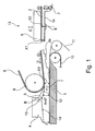
In der
Im weiteren Verlauf des Endlosförderbandes 5 wird der Tabakstrang 2 zu der in Transportrichtung T des Tabakstranges 2 letzten Umlenkrolle 6, an der das Endlosförderband 5 anliegt, geführt und läuft dabei auf eine kontinuierlich zugeführte, Hüllbahn 11 auf. Die Hüllbahn 11 wird von einem in Transportrichtung T angetriebenen Formatband 10 geführt, das wiederum auf einem Formatgrund 1 aufliegt. Der Formatgrund 1 bildet eine Unterstützungsfläche und ist entsprechend dem zu formenden stabförmigen Produkt mit einer Rinne mit einem sich kontinuierlich verkleinernden Radius versehen, in der das Formatband 10 mit der Hüllbahn 11 und dem daraufgelegten Tabakstrang 2 geführt ist.In the further course of the
Die Umlenkrolle 6 ist in einem Abstand x3 zu dem Formatgrund 1 ausgerichtet, welcher abzüglich der Dicke des Endlosförderban-des 5, der Dicke der Hüllbahn 11 und der Dicke des Formatbandes 10 der ersten Höhe x1 des Tabakstranges 2 im Rahmen eines Toleranzbereichs von +/- 0,5 mm entspricht. Der vorgeschlagene Abstand der Umlenkrolle 6 zu dem Formatgrund 1 hat sich für den weiteren kontinuierlichen Transport des Tabakstranges 2 als ideal herausgestellt. Mit dem Beginn der Krümmung des Endloszugmittels 5 beginnt sich der Tabakstrang 2 von dem Endlosförderband 5 zu lösen, wobei der Ablösevorgang durch einen Schaber 3 unterstützt wird, der mit seiner Spitze in einem Abstand 0,05 - 0,3 mm zu dem Endlosförderband 5 angeordnet ist. Außerdem liegt an dem Endlosförderband 5 kein Vakuum mehr an, wenn es auf die Umlenkrolle 6 aufläuft, so dass gleichzeitig die durch das Vakuum auf den Tabakstrang 2 ansonsten ausgeübte Haltekraft verringert wird und schließlich nicht mehr vorhanden ist, wodurch sich der Tabakstrang 2 selbsttätig durch sein Eigengewicht von dem Endlosförderband 5 löst. Der Tabakstrang 2 wird in dem Übergang von dem Endlosförderband 5 auf die Hüllbahn 11 kurzzeitig in dem engsten Querschnitt zwischen der Umlenkrolle 6 und dem Formatgrund 1 komprimiert und wird dadurch mit einer bestimmten Anpresskraft auf die Hüllbahn 11 gepresst, welche einen störungsfreien Weitertransport des Tabakstranges ermöglicht.The
Der Schaber 3 ist mit einer Grundfläche 12 versehen, welche derart geformt ist, dass der Abstand zwischen der Grundfläche 12 und dem Formatgrund 1 in Transportrichtung T des Tabakstranges 2 zunimmt. Die Zunahme des Abstandes ist in der Darstellung als Winkel A größer als 0 Grad dargestellt. Der Schaber 3 ist ferner mit einer in der Befestigungsstellung senkrecht zu dem Formatgrund 1 ausgerichteten Anlagefläche 15 versehen, so dass der sich vergrößernde Abstand zwischen der Grundfläche 12 und dem Formatgrund 1 auch durch den Winkel B zwischen der Grundfläche 12 und der Anlagefläche 15 von vorzugsweise 90,5 bis 96 Grad und insbesondere von 92 bis 94,5 Grad ergibt. Der Winkel A kann besonders einfach durch die Verwendung eines Schabers 3 mit einem anderen Winkel B verändert werden. Die Anlagefläche 15 des Schabers 3 befindet sich in der Befestigungsstellung in Anlage an einer ebenfalls senkrecht zu dem Formatgrund 1 ausgerichteten Anlagefläche eines Fingers 4, welcher in Transportrichtung T des Tabakstranges 2 hinter dem Schaber 3 angeordnet ist. Der Finger 4 ist an seiner dem Formatgrund 1 zugewandten Seite mit einer Anpressfläche 14 versehen, welche derart geformt ist, dass der Abstand zwischen der Anpressfläche 14 und dem Formatgrund 1 in Transportrichtung T abnimmt. Im Übergang von der Grundfläche 12 zu der Anpressfläche 14 ist sinnvollerweise eine Stufe, gebildet durch einen Materialüberschuss der Grundfläche 12, vorgesehen, welcher einen Verschleißvorrat darstellt und verhindert, dass der Tabakstrang 2 mit der Oberfläche an einer Kante der Anpressfläche 14 anläuft. Sofern die Anlagefläche 15 an der Einrichtung in einem schiefen Winkel zu der Senkrechten angeordnet ist, kann der Winkel B auch kleiner als 90 Grad gewählt werden, wobei in diesem Fall die Summe aus dem Winkel zwischen der Anlagefläche 15 und der Senkrechten und dem Winkel B größer als 90 Grad sein sollte, um den erfindungsgemäßen Erfolg herbeizuführen. Der Finger 4 ist dabei unmittelbar an dem Schaber 3 angeordnet, so dass zwischen beiden Teilen in Transportrichtung T des Tabakstranges kein Spalt vorhanden ist. Die Grundfläche 12 geht dadurch in Transportrichtung T unmittelbar in die Anpressfläche 14 über. Da der Schaber 3 und der Finger 4 jeweils als dickwandige Bauteile ohne Hohlräume ausgebildet sind, können diese sehr genau aus einem Vollmaterial hergestellt werden. Als Herstellungsverfahren bieten sich alle spanabhebenden Verfahren sowie Erodieren an. Ferner können die Bauteile so bemessen werden, dass die daran angeordnete Grundfläche 12 und Anpressfläche 14 auch bei einer hohen mechanischen und thermischen Beanspruchung eine hohe Formtreue aufweisen.The
Die Formgebung des Tabakstranges 2 erfolgt dabei einerseits durch die in dem Formatgrund 1 befindliche Rinne und andererseits durch die profilierte Grundfläche 12 des Schabers und die Anpressfläche 14 des Fingers 4. Da der Abstand zwischen der Grundfläche 12 und dem Formatgrund 1 in Transportrichtung T zunimmt, kann sich der Tabakstrang 2 nach dem kurzzeitigen Komprimieren in dem engsten Querschnitt zumindest geringfügig aufweiten. Aufgrund des lediglich kurzzeitigen Komprimierens des Tabakstranges 2 in dem engsten Querschnitt wird sichergestellt, dass die relative Lage der Köpfe, d. h. der Abschnitte 2a, in dem Tabakverbund zu dem Tabakmittelstrang nicht verändert wird. Als Tabakmittelstrang wird der Grundkörper des Tabakstranges 2 bezeichnet, welcher durch die Abschnitte mit der ersten Höhe x1 gebildet wird.The shape of the
Ferner kann der Tabakstrang 2 nach dem Ablauf von der Grundfläche 12 von einer größeren Querschnittsfläche an der Eintrittsseite des Fingers 4 auf eine wesentlich kleinere Querschnittsfläche mit einem erheblich größeren Umformgrad verformt werden, als dies bei den im Stand der Technik bekannten Lösungen möglich war. Die eigentliche Formgebung des Tabakstranges 2 findet demnach zwischen der Anpressfläche 14 und dem Formatgrund 1 statt. Der Abstand y zwischen der Anpressfläche 14 an der Austrittsseite des Tabakstranges 2 und dem Formatband 10 entspricht dabei ungefähr dem Durchmesser des fertigen Produktes minus 0,6 bis 1,5 mm. Der Finger 4 ist in der beschriebenen Ausführungsform als gesondertes Einzelteil ausgeführt, er kann jedoch auch einstückig an den Schaber 3 mit angeformt werden, wodurch die Teileanzahl reduziert werden kann.Furthermore, the
Insgesamt kann der Tabakstrang 2 durch die vorgeschlagene Lösung zwischen der Anpressfläche 14 und dem Formatgrund 1 wesentlich prozesssicherer zu einer Sollform mit einer Solldichteverteilung geformt werden, da die Verformung des Tabakstranges 2 mit einer größeren Querschnittsfläche beginnt. Dadurch kann die Solldichte und Sollposition der Köpfe in dem Tabakstrang 2 wesentlich genauer eingehalten werden, und es wird verhindert, dass der nicht zu vermeidende Kopfausfall einen vorbestimmten Grenzwert überschreitet.Overall, the
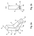
In den
Alternativ kann der Radius der Grundfläche 12 in Transportrichtung T des Tabakstranges 2 auch konstant sein. In diesem Fall ist der sich erweiternde Abstand der Grundfläche 12 von dem Formatgrund 1 dadurch verwirklicht, indem die Rinne mit konstantem Radius, welche die Grundfläche 12 bildet, schief an dem Schaber 3 angeordnet ist. Die Rinne kann z.B. mit einer konstanten Tiefe in der Grundfläche 12 oder auch mit einer zunehmenden Tiefe in der Grundfläche 12 verlaufen.Alternatively, the radius of the base 12 in the transport direction T of the
In der
Es ist selbstverständlich, dass auch eine verstellbare Umlenkrolle 6 mit einem verstellbaren Führungsschuh 16 in Kombination vorgesehen werden kann, wodurch sich eine weiter verbesserte Führung des Tabakstranges 2 und Übergabe des Tabakstranges 2 auf das Formatband 10 bzw. Aufgabe des Tabakstranges 2 auf die Hüllbahn 11 erzielen lässt.It is self-evident that an
Claims (12)
Applications Claiming Priority (2)
| Application Number | Priority Date | Filing Date | Title |
|---|---|---|---|
| DE102010025548 | 2010-06-29 | ||
| DE201110100365 DE102011100365A1 (en) | 2010-06-29 | 2011-05-03 | Device for producing rod-shaped products of the tobacco-processing industry |
Publications (2)
| Publication Number | Publication Date |
|---|---|
| EP2401928A2 true EP2401928A2 (en) | 2012-01-04 |
| EP2401928A3 EP2401928A3 (en) | 2014-10-01 |
Family
ID=44508575
Family Applications (1)
| Application Number | Title | Priority Date | Filing Date |
|---|---|---|---|
| EP11004862.6A Withdrawn EP2401928A3 (en) | 2010-06-29 | 2011-06-15 | Device for producing rod-shaped articles from the tobacco processing industry |
Country Status (3)
| Country | Link |
|---|---|
| EP (1) | EP2401928A3 (en) |
| CN (1) | CN102326862A (en) |
| DE (1) | DE102011100365A1 (en) |
Cited By (1)
| Publication number | Priority date | Publication date | Assignee | Title |
|---|---|---|---|---|
| IT201700017823A1 (en) * | 2017-02-17 | 2018-08-17 | Gd Spa | Machine for producing at least one continuous silkworm of filter material or tobacco. |
Families Citing this family (3)
| Publication number | Priority date | Publication date | Assignee | Title |
|---|---|---|---|---|
| RU2697045C2 (en) | 2014-12-16 | 2019-08-08 | Филип Моррис Продактс С.А. | Casting machine for production of cast web from homogenised tobacco material |
| JP6665178B2 (en) * | 2014-12-16 | 2020-03-13 | フィリップ・モーリス・プロダクツ・ソシエテ・アノニム | Casting equipment for the production of cast webs of homogenized tobacco material |
| CN115836743A (en) * | 2022-12-01 | 2023-03-24 | 浙江中烟工业有限责任公司 | Tobacco cutter device of cigarette making machine |
Citations (1)
| Publication number | Priority date | Publication date | Assignee | Title |
|---|---|---|---|---|
| DE3407068A1 (en) | 1983-04-27 | 1984-10-31 | The Japan Tobacco & Salt Public Corp., Tokio/Tokyo | TONGUE FOR THE PRODUCTION OF CIGARETTE RODS |
Family Cites Families (14)
| Publication number | Priority date | Publication date | Assignee | Title |
|---|---|---|---|---|
| GB1578140A (en) * | 1976-07-14 | 1980-11-05 | Molins Ltd | Cigarette manufacture |
| DE3103056A1 (en) * | 1980-03-07 | 1982-02-04 | Hauni-Werke Körber & Co KG, 2050 Hamburg | Arrangement for the production of cigarettes with reinforced ends |
| US4605013A (en) * | 1983-02-02 | 1986-08-12 | Hauni-Werke Korber & Co. Kg | Method and apparatus for forming discrete batches of tobacco particles |
| IT1168681B (en) * | 1983-09-12 | 1987-05-20 | Gd Spa | CONTINUOUS TYPE CIGARETTES PACKAGING MACHINE |
| DE3508497A1 (en) * | 1985-03-09 | 1986-09-11 | Hauni-Werke Körber & Co KG, 2050 Hamburg | METHOD AND DEVICE FOR MAKING TOBACCO PORTIONS, ESPECIALLY FOR THE PRODUCTION OF A TOBACCO STRAND MADE FROM SEPARATE TOBACCO SECTIONS OF DIFFERENT KINDS |
| DE3701278A1 (en) * | 1986-01-30 | 1987-08-06 | Hauni Werke Koerber & Co Kg | Method and machine for filling tubes for rod-shaped articles in the tobacco processing industry |
| CH686334A5 (en) * | 1991-01-31 | 1996-03-15 | Tabac Fab Reunies Sa | cigarette machine. |
| DE4218258A1 (en) * | 1992-06-03 | 1993-12-09 | Decoufle Sarl | Formation of tobacco strand for mass prodn. of cigarettes - involves tapered channel with central rib to mould wrapping band round strand |
| JP3248682B2 (en) * | 1998-01-12 | 2002-01-21 | 日本たばこ産業株式会社 | Chopped cigarette layer compression molding machine for cigarette making machine |
| DE19909216A1 (en) * | 1999-03-03 | 2000-09-07 | Hauni Maschinenbau Ag | Device for building up a continuous tobacco rod |
| US7117871B2 (en) * | 2002-12-20 | 2006-10-10 | R.J. Reynolds Tobacco Company | Methods for manufacturing cigarettes |
| DE102004039325A1 (en) * | 2004-08-12 | 2006-02-23 | Hauni Maschinenbau Ag | Delivery of strand material |
| DE102005021817A1 (en) * | 2005-05-04 | 2006-11-09 | Hauni Maschinenbau Ag | Backing for one or each separating element of a release agent and device for separating smokable material, such. As tobacco, tobacco ribs, tobacco foil and / or cloves of a compressed cake |
| DE102006045810B4 (en) * | 2006-09-26 | 2012-02-16 | Hauni Maschinenbau Ag | Suction-belt conveyor and method for producing a strand of the tobacco-processing industry |
-
2011
- 2011-05-03 DE DE201110100365 patent/DE102011100365A1/en not_active Ceased
- 2011-06-15 EP EP11004862.6A patent/EP2401928A3/en not_active Withdrawn
- 2011-06-28 CN CN2011101763177A patent/CN102326862A/en active Pending
Patent Citations (1)
| Publication number | Priority date | Publication date | Assignee | Title |
|---|---|---|---|---|
| DE3407068A1 (en) | 1983-04-27 | 1984-10-31 | The Japan Tobacco & Salt Public Corp., Tokio/Tokyo | TONGUE FOR THE PRODUCTION OF CIGARETTE RODS |
Cited By (2)
| Publication number | Priority date | Publication date | Assignee | Title |
|---|---|---|---|---|
| IT201700017823A1 (en) * | 2017-02-17 | 2018-08-17 | Gd Spa | Machine for producing at least one continuous silkworm of filter material or tobacco. |
| EP3363302A1 (en) * | 2017-02-17 | 2018-08-22 | G.D. S.p.A | Machine for making at least one continuous rod of filter material or tobacco |
Also Published As
| Publication number | Publication date |
|---|---|
| EP2401928A3 (en) | 2014-10-01 |
| CN102326862A (en) | 2012-01-25 |
| DE102011100365A1 (en) | 2011-12-29 |
Similar Documents
| Publication | Publication Date | Title |
|---|---|---|
| EP1968757B1 (en) | Method and device for producing bent spring elements | |
| EP2521640B1 (en) | Method and device for producing a composite fibre material in the form of a fibre strip impregnated with a polymer | |
| DE202016008856U1 (en) | Thermoforming packaging machine | |
| EP2401928A2 (en) | Device for producing rod-shaped articles from the tobacco processing industry | |
| EP0608861A2 (en) | Method and apparatus for feeding sensitive objects to a processing machine | |
| EP3235388B1 (en) | Device for applying a glue track to a covering strip of a rod-shaped product of the tobacco processing industry | |
| EP2641483A1 (en) | Format device of a strand machine | |
| EP2505269A2 (en) | Device for gluing a moved cover strip for rod-shaped products for the tobacco processing industry and assembly with such a device | |
| EP4013246B1 (en) | Providing metal strip portions for tobacco segments | |
| DE102014116270B3 (en) | Plant and method for the continuous production of curved preforms | |
| EP3144133A1 (en) | Adevice for making a groove in sheets of material | |
| DE10035461B4 (en) | Method and device for molding a confectionery mass | |
| EP1625797B1 (en) | Delivery of strand material | |
| DE2414262A1 (en) | METHOD AND DEVICE FOR STRIP ASSEMBLY OF FASTENING ELEMENTS | |
| EP2484232A2 (en) | Rod making machine for producing products for the tobacco industry and garniture for a rod making machine and method for controlling the machine | |
| EP2713708B1 (en) | Method and device for casting a cheese curd | |
| EP2570206A1 (en) | Profile rolling machine | |
| EP4100243B1 (en) | Production machine for producing rod-shaped products from an endless strand of a strip adhesively bonded to form a tube | |
| EP3283263B1 (en) | Slicing device having an injecting device for an interleaving paper | |
| EP2311329B1 (en) | Feeding of rod-shaped articles from the tobacco processing industry | |
| EP1897454B1 (en) | V-shaped assembly of suction apertures | |
| EP2756768B2 (en) | Device for longitudinally conveying rod-shaped products in the tobacco processing industry | |
| DE10354797A1 (en) | Method and device for producing a wrapping material strip-free filter strand of the tobacco processing industry | |
| EP0814922B1 (en) | Installation for cutting off several thread lengths from a skein of thread material | |
| DE102004055799B3 (en) | Lead manufacturing method for e.g. writing purpose, involves pressing lead mass to strand, and transporting strand on path to cutting station, where distance is maintained between lower side of strand and path by using fluid flow |
Legal Events
| Date | Code | Title | Description |
|---|---|---|---|
| AK | Designated contracting states |
Kind code of ref document: A2 Designated state(s): AL AT BE BG CH CY CZ DE DK EE ES FI FR GB GR HR HU IE IS IT LI LT LU LV MC MK MT NL NO PL PT RO RS SE SI SK SM TR |
|
| AX | Request for extension of the european patent |
Extension state: BA ME |
|
| PUAI | Public reference made under article 153(3) epc to a published international application that has entered the european phase |
Free format text: ORIGINAL CODE: 0009012 |
|
| PUAL | Search report despatched |
Free format text: ORIGINAL CODE: 0009013 |
|
| AK | Designated contracting states |
Kind code of ref document: A3 Designated state(s): AL AT BE BG CH CY CZ DE DK EE ES FI FR GB GR HR HU IE IS IT LI LT LU LV MC MK MT NL NO PL PT RO RS SE SI SK SM TR |
|
| AX | Request for extension of the european patent |
Extension state: BA ME |
|
| RIC1 | Information provided on ipc code assigned before grant |
Ipc: A24C 5/18 20060101AFI20140827BHEP |
|
| STAA | Information on the status of an ep patent application or granted ep patent |
Free format text: STATUS: THE APPLICATION IS DEEMED TO BE WITHDRAWN |
|
| 18D | Application deemed to be withdrawn |
Effective date: 20150106 |