EP0608861A2 - Procédé et dispositif pour alimenter des objets sensibles dans une machine de traitement - Google Patents
Procédé et dispositif pour alimenter des objets sensibles dans une machine de traitement Download PDFInfo
- Publication number
- EP0608861A2 EP0608861A2 EP94101129A EP94101129A EP0608861A2 EP 0608861 A2 EP0608861 A2 EP 0608861A2 EP 94101129 A EP94101129 A EP 94101129A EP 94101129 A EP94101129 A EP 94101129A EP 0608861 A2 EP0608861 A2 EP 0608861A2
- Authority
- EP
- European Patent Office
- Prior art keywords
- conveyor
- objects
- driver
- feed
- input
- Prior art date
- Legal status (The legal status is an assumption and is not a legal conclusion. Google has not performed a legal analysis and makes no representation as to the accuracy of the status listed.)
- Withdrawn
Links
Images


Classifications
-
- B—PERFORMING OPERATIONS; TRANSPORTING
- B65—CONVEYING; PACKING; STORING; HANDLING THIN OR FILAMENTARY MATERIAL
- B65G—TRANSPORT OR STORAGE DEVICES, e.g. CONVEYORS FOR LOADING OR TIPPING, SHOP CONVEYOR SYSTEMS OR PNEUMATIC TUBE CONVEYORS
- B65G47/00—Article or material-handling devices associated with conveyors; Methods employing such devices
- B65G47/22—Devices influencing the relative position or the attitude of articles during transit by conveyors
- B65G47/26—Devices influencing the relative position or the attitude of articles during transit by conveyors arranging the articles, e.g. varying spacing between individual articles
- B65G47/30—Devices influencing the relative position or the attitude of articles during transit by conveyors arranging the articles, e.g. varying spacing between individual articles during transit by a series of conveyors
- B65G47/31—Devices influencing the relative position or the attitude of articles during transit by conveyors arranging the articles, e.g. varying spacing between individual articles during transit by a series of conveyors by varying the relative speeds of the conveyors forming the series
Definitions
- the invention relates to a method for feeding sensitive objects, in particular confectionery, to a processing machine, in particular packaging machine, with a machine-side pick-up device, to which the objects are fed to the processing machine in accordance with a machine cycle by a plurality of subsequent conveyors.
- the invention also relates to a device for the precise positional feeding of such objects according to a machine cycle of the processing machine with at least one conveying device which conveys the objects in a single lane and singly and a feed conveyor arranged downstream of the same, a circulating conveying means and carriers fixed to the latter for feeding the objects along guideways to the conveyor Processing machine has, with the objects in contact with the carriers of the feed conveyor.
- a method and a device of the aforementioned type are known from DE-OS 33 39 793.
- This shows a feed device for a packaging machine for chocolate bars consisting of several conveyor belts arranged in succession, the bars aligned on a monitoring belt in their longitudinal axis first being fed to a feed belt.
- the circulating speed of the feed belt is lower than the circulating speed of the monitoring belt. This causes the bars to jam, the rotational speeds of both conveyor belts being regulated and matched to the machine cycle of the packaging machine in such a way that the bars jam back onto the monitoring belt, the length of the jam being checked.
- the pieces are separated again on the subsequent acceleration belt.
- the acceleration belt consists of two parallel belts arranged next to each other with the same rotational speed. A space is provided between the belts for the catches of a driver chain of the feed conveyor, which is partially arranged under the belts, to reach through.
- the acceleration belts run faster than the feed belt. This again creates gaps in which the drivers of the chain of the feed conveyor engage.
- the drivers of the loading conveyor run in a machine cycle and have a slightly higher rotational speed than the acceleration belts. As a result, the drivers rest on the rear edge of the transom and there can be a slight pushing movement on the acceleration belts.
- the drivers of the driver chain rest on the rear edge of the bars.
- the bars are guided on the loading conveyor by its driver to the work organs of the packaging machine in the machine cycle.
- a servo motor is provided for controlling the feed device, which controls the circulating speed of the feed belt.
- a base speed of the feed belt is set which always remains below the speed corresponding to the machine cycle.
- a sensor determines the instantaneous position of a bolt when it is transferred from the feed belt to the acceleration belts and temporarily shifts the base clock so that the locks are positioned precisely in relation to the drivers of the driver chain.
- the aforementioned feed device is disadvantageous in that it is not suitable for high-performance packaging machines that run with very high machine cycle rates and for processing very sensitive piece goods.
- the invention is therefore based on the object of specifying a method and a device of the type mentioned at the outset for the precise positioning of sensitive objects (piece goods) at high processing speeds, by means of which the dynamic loads to which the conveyed objects are exposed are kept at an extremely low level can without significantly increasing effort and space requirements.
- this object is achieved according to the invention in a method of the type mentioned at the outset in that the objects are separated upstream of a loading conveyor which interacts with the pickup device and are placed on the loading conveyor with the engagement of drivers of a driving conveyor.
- a driver conveyor is arranged at least partially above the conveyor device, the drivers of which are in contact with the objects at least in the area of a transfer from the conveyor device to the loading conveyor.
- the solution according to the invention creates a method and a device for high-performance processing machines, in particular packaging machines, which at high speeds enable a single-track and currently unique, positionally accurate provision of the objects with high protection by largely eliminating dynamic loads.
- packaging services of approx. 1300 pieces / min. can be achieved.
- confectionery pieces with a length of approximately 26 mm and a relatively soft consistency are used as processing goods (objects).
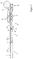
- the confectionery pieces 1 are aligned in one lane by means not shown here and fed to an alloting belt 3 via a storage belt 2.
- a servo motor M is assigned to the feed belt 3.
- the servo motor M is used to control the circulating speed V3 of the feed belt 3. This is significantly lower than the circulating speed V2 of the accumulating belt 2.
- Both circulating speeds V2, V3 are coordinated with one another in such a way that the confectionery pieces 1 lie on the feed belt 3 without gaps. This position is stabilized on the feed belt 3 by applying a negative pressure represented by arrows in FIG. 1.
- the confectionery pieces 1 reach the input belt 4 from the feed belt 3.
- the deflection rollers 5, the so-called knife edges, assigned to the feed belt 3 and the input belt 4 have the smallest constructionally possible diameter around the deflection rollers 5 of the feed belt 3 and Arrange the conveyor belt 2 as close as possible and to keep the gap between the two conveyors 3, 4 as small as possible.
- deflection rollers 5 with a diameter of approximately 8 mm are used, for example, with adjacent conveyor belts, i.e., between the deflection rollers 5. Between the accumulation belt 2 and the feed belt 3 or between the feed belt 3 and the feed belt 4 there is a distance of approximately 10 mm. This can be bridged by a confectionery piece 1. I.e. the base of a confectionery piece 1 in the conveying direction is larger than the distance between adjacent conveyor belts 2, 3, 4, so that (slightly differently than shown in FIG.
- the confectionery pieces 1 can be passed between the conveyors 3, 4 during the transfer from the feed belt 3 to the input belt 4 with only slight deviations from the conveying direction with regard to their orientation on the conveyor belts.
- the circulation speed V4 of the input belt 4 is approximately twice as high as the circulation speed V3 of the feed belt 3.
- the confectionery pieces 1 are separated again at a transfer point 6 between the feed and input conveyors 3, 4 after the previous stowage. This is intended to achieve a defined position for the machine cycle of a packaging machine on which the feed device is arranged.
- the circulation speeds V3, V4 and due to the inevitable gap at the transfer point 6 between the feed belt 3 and the feed belt 4 there is a risk that the confectionery pieces 1 receive a mechanical impulse and thus with regard to the machine cycle of the subsequent one Packaging machine assume a different position on the input belt 4 that does not conform to the machine cycle.
- the structure of the input belt 4 is similar to that of the feed belt 3.
- the vacuum on the feed belt 4 is graded in height over the length of the feed belt 4, as shown in FIG. 1 by arrows of different lengths is indicated. Due to a relatively high and in particular the negative pressure at the end of the feed belt 3 exceeding negative pressure at the beginning of the input conveyor 4, i.e. in the area of the transfer point 6, a precise takeover of the confectionery pieces 1 is achieved.
- the position of the confectionery pieces 1 is stabilized by a lower negative pressure in the central region of the input belt 4. There is no negative pressure at the end of the input belt 4.
- the transfer point 6 between the feed belt 3 and the feed belt 4 is shown in detail schematically and enlarged in FIG. 2.
- the upper run 3a of the feed belt 3 or the upper run 4a of the feed belt 4 are each guided over plates 7 and for deflection over the deflection rollers 5, both plates 7 having an end slanted towards the respective deflection roller 5 with a correspondingly enlarged air passage opening 8
- the desired pressure distribution and gradation of the negative pressure is achieved on the input belt 4 side.
- the clear width of the passage openings 8 decreases in the transport direction of the input belt 4 and the negative pressure is set in the desired manner by appropriate spacing of the air passage openings 8.
- Both the feed belt 3 and the feed belt 4 regularly not shown here Intervals arranged air passage openings, which allow the confectionery pieces 1 to be held in place by the negative pressure applied to the plates 7.
- the position of the confectionery pieces 1 on the input belt 4 is additionally detected with respect to their actual position by optical means (light barrier) not shown here, and the actual position values determined are compared in a conventional manner with the nominal position values. If the setpoint / actual value comparison shows that confectionery pieces 1 are outside the tolerance range, they are ejected by an ejector device, not shown here, which is arranged upstream of a driver conveyor 10, which will be explained in more detail below.
- the circulating speed of the feed belt 3 is changed by the servo motor M until the confectionery pieces 1 are again within the tolerance range with regard to their actual position on the input conveyor 4. This plays a role in particular in the non-stationary operation of the feed device, e.g. when starting up the entire system.
- the circulation speed V3 of the feed belt 3 is the only controllable circulation speed V in connection with the separation of the confectionery pieces 1.
- a return belt 9 is arranged according to the invention in the conveying direction following the input belt 4.
- an upper driver conveyor 10 which is designed as an upper driver toothed belt.
- the input belt 4 and the return belt 9 are in a conventional manner by means of the deflection roller mechanism schematically shown in the figures with the deflection rollers 5 of small diameter driven. Rolling knife edges are also used here in order to guide the confectionery pieces 1 during the transfer from the input belt 4 to the return belt 9 or from the return belt 9 to guide rails 13 of a downstream feed conveyor 12 with only slight deviations from the conveying direction via the transfer points.
- the guide of the upper driving toothed belt 10 is designed so that its driving 11 gradually and progressively engages on a circular arc with a relatively small diameter into the gaps between the confectionery pieces 1 and also gradually progresses again above of the feed conveyor 12 emerge from these spaces.
- a lower run 10a of the driver conveyor 10 is first inclined downwards in the conveying direction and then inclined upwards in the conveying direction.
- the lower run 10a of the entraining conveyor 10 can also be arranged parallel to the conveying direction (parallel to the input and return conveyor 4, 9) between the deflection rollers 10b and 10c.
- the driver conveyor 10 is adjustable, so that in particular the inclination of the driver conveyor 10 to run in can be adjusted depending on the size and shape of the confectionery pieces 1.
- the upper driving toothed belt 10 partially covers the input belt 4, extends over the return conveyor 9 and partially covers the subsequent guide rails 13 of the loading conveyor 12, i.e. the engagement of the drivers 11 in the area between the individual confectionery pieces 1 begins a few cycles before the transfer from the input belt 4 to the return belt 9 and ends behind the area of the transfer from the return belt 9 to the guide rails 13 of the loading conveyor 12.
- the distance between the drivers 11 of the driver toothed belt 10 is due to the design and is determined by the size and the nature of the confectionery pieces 1 to be processed.
- the clear width between the drivers is 11 46 mm.
- the tolerance range with regard to the position of the pieces on the input belt 4 is selected so that the clear width between the drivers 11 of the upper driver toothed belt 10 is sufficient to place the confectionery pieces 1 securely between two drivers 11 of the driver toothed belt 10.
- the drivers 11 of the driver toothed belt 10 increasingly engage in the spaces between the confectionery pieces 1 at the end of the input conveyor 4 and on the return conveyor 9, i.e. the confectionery pieces 1 increasingly get between two drivers 11 of the driver toothed belt. In this position, the confectionery pieces 1 are conveyed onto the return belt 9.
- the circulating speed V9 of the return belt 9 is lower than the circulating speed V10 of the upper driving toothed belt 10.
- Both circulating speeds V9, V10 are coordinated with one another in such a way that a relative displacement of the confectionery pieces 1 takes place with respect to their position between two drivers 11 and at the downstream end of the return belt 9 in The area of the transfer to the guide rails 13 of the feed conveyor 12, the confectionery pieces 1 with the upper area of their rear side each abut against the drivers 11 of the driver conveyor 10.
- a lower driving toothed belt 14 is assigned to the guide rails 13 of the feed conveyor 12.
- the guide rails 13 of the Feed conveyor 12 are spaced parallel to each other and engage in the space between the driver rails 13 driver 15 of the feed conveyor 12 and are guided therein.
- An abrasion-resistant and extremely slidable plastic is used as the material for the guide rails 13, which enables the confectionery pieces to slide easily, moved by the carriers 15 of the loading conveyor 12.
- a synchronous pulley 16 assigned to the lower driving toothed belt 14 of the feed conveyor 12 has a constructionally substantially larger diameter than the deflection rollers 5.
- a bridge 17 is arranged at the transition from the return belt 9 to the guide rails 13. The bridge 17 has a recess in the middle, not shown here, to allow the passage of the drivers 15 of the feed conveyor 12.
- the confectionery pieces 1 are transferred from the return belt 9 to the loading conveyor 12 (lower driving toothed belt 14) via the bridge 17.
- the confectionery pieces 1 are conveyed onto the bridge 17 and the drivers 15 of the loading conveyor 12 capture the confectionery pieces through the recess in the bridge 17 1 and convey them along the guide rails 13 of the feed conveyor 12 to a pick-up device 18 of the packaging machine (not shown further here).
- the driver conveyor 10 (upper driver toothed belt) also has the function of pushing the confectionery pieces 1 over the bridge 17 and thus ensuring a correct transfer to the drivers 15 of the loading conveyor 12.
- the drivers 15 of the loading conveyor 12 and the drivers of the driving conveyor 10 are in opposing opposite positions.
- the circulating speeds V10 of the driving conveyor 10 (upper driving toothed belt) and V12 of the loading conveyor 12 (lower Driving toothed belts) are the same and the exact position of the confectionery pieces 1 corresponding to the machine cycle of the packaging machine is thus achieved.
- the confectionery pieces 1 are fed by the feed conveyor 12 or by its driver 15 along the guide rails 13 to the pick-up device 18 of the packaging machine.
- Individual confectionery pieces which, in exceptional cases, do not yet lie against a driver with the upper region of their rear side, overcome any gap that may still exist due to the friction along the guide rails 13 and come into contact with the driver 15 concerned of the loading conveyor 12 Transfer point to the pick-up device 18 of the packaging machine is thus an exactly defined position of the confectionery pieces 1 even at high operating speeds of the packaging machine.
Landscapes
- Engineering & Computer Science (AREA)
- Mechanical Engineering (AREA)
- Attitude Control For Articles On Conveyors (AREA)
- Special Conveying (AREA)
- Belt Conveyors (AREA)
- Intermediate Stations On Conveyors (AREA)
- Specific Conveyance Elements (AREA)
- Structure Of Belt Conveyors (AREA)
Applications Claiming Priority (2)
| Application Number | Priority Date | Filing Date | Title |
|---|---|---|---|
| DE4302575 | 1993-01-29 | ||
| DE19934302575 DE4302575A1 (de) | 1993-01-29 | 1993-01-29 | Einrichtung zum Zuführen kleiner empfindlicher Stückgüter |
Publications (2)
| Publication Number | Publication Date |
|---|---|
| EP0608861A2 true EP0608861A2 (fr) | 1994-08-03 |
| EP0608861A3 EP0608861A3 (fr) | 1995-01-11 |
Family
ID=6479255
Family Applications (1)
| Application Number | Title | Priority Date | Filing Date |
|---|---|---|---|
| EP94101129A Withdrawn EP0608861A3 (fr) | 1993-01-29 | 1994-01-26 | Procédé et dispositif pour alimenter des objets sensibles dans une machine de traitement. |
Country Status (5)
| Country | Link |
|---|---|
| EP (1) | EP0608861A3 (fr) |
| JP (1) | JPH06305552A (fr) |
| BR (1) | BR9400240A (fr) |
| DE (1) | DE4302575A1 (fr) |
| TW (1) | TW263483B (fr) |
Cited By (9)
| Publication number | Priority date | Publication date | Assignee | Title |
|---|---|---|---|---|
| EP0703167A1 (fr) * | 1994-09-26 | 1996-03-27 | Dimac S.P.A. | Dispositif pour assembler des produits alimentés en continu |
| DE19546496A1 (de) * | 1995-12-13 | 1997-06-19 | Bielomatik Leuze & Co | Vorrichtung zum Fördern von Blattlagen |
| EP0806380A1 (fr) * | 1996-05-08 | 1997-11-12 | AZIONARIA COSTRUZIONI MACCHINE AUTOMATICHE-A.C.M.A.-S.p.A. | Procédé et dispositif pour orienter des produits |
| DE19625470A1 (de) * | 1996-06-26 | 1998-01-02 | Bielomatik Leuze & Co | Verfahren und Vorrichtung zur Förderung von Gegenständen |
| EP0872436A1 (fr) | 1997-04-16 | 1998-10-21 | Pactec Verpackungsmaschinen-Fabrik Theegarten GmbH & Co. KG | Méthode pour séparer des petits objets et appareil de séparation |
| EP0885823A1 (fr) * | 1997-06-20 | 1998-12-23 | Klöckner Hänsel Tevopharm B.V. | Dispositif de transport pour accélérer une série de produits |
| EP2704967B1 (fr) | 2011-05-03 | 2016-05-18 | Robert Bosch GmbH | Procédé pour faire fonctionner un système de transfert électromagnétique et système de transfert |
| CN114768605A (zh) * | 2022-05-27 | 2022-07-22 | 安徽金源药业有限公司 | 一种基于工业互联网的自动定量投料制药设备 |
| CN115072347A (zh) * | 2021-03-10 | 2022-09-20 | 法麦凯尼柯数据股份公司 | 用于改变移动的物品之间的间距的设备和方法 |
Families Citing this family (10)
| Publication number | Priority date | Publication date | Assignee | Title |
|---|---|---|---|---|
| DE19529139A1 (de) * | 1995-08-08 | 1997-02-13 | Focke & Co | Vorrichtung zum geordneten Transport von Packungen, insbesondere in Verbindung mit einem Etikettierer |
| DE29701124U1 (de) * | 1997-01-23 | 1997-03-13 | Kunnemeyer Hornitex | Vorrichtung für den Transport und für eine exakte Lagepositionierung von plattenförmigen, rechteckigen Werkstücken |
| US6322467B1 (en) | 1997-06-30 | 2001-11-27 | Jervis B. Webb Company | Movable backup bar assembly |
| JP3815016B2 (ja) * | 1997-12-15 | 2006-08-30 | 井関農機株式会社 | 育苗施設 |
| JP2000044029A (ja) * | 1998-07-27 | 2000-02-15 | Mitsui Miike Mach Co Ltd | 空気浮上式ベルトコンベヤ |
| JP2003128233A (ja) * | 2001-10-26 | 2003-05-08 | Ikegami Tsushinki Co Ltd | 小物物品の供給整列搬送装置 |
| JP5399353B2 (ja) * | 2010-09-10 | 2014-01-29 | 株式会社フジキカイ | 物品搬送装置 |
| DE102011075174A1 (de) | 2011-05-03 | 2012-11-08 | Robert Bosch Gmbh | Transfereinrichtung für Gegenstände |
| CN109230422A (zh) * | 2018-09-28 | 2019-01-18 | 中科天工(武汉)智能技术有限公司 | 一种纸盒成型的内模供送装置及方法 |
| CN111824719B (zh) * | 2020-07-30 | 2021-12-17 | 江苏国富氢能技术装备股份有限公司 | 一种铝内胆生产线中的上料输送装置 |
Citations (3)
| Publication number | Priority date | Publication date | Assignee | Title |
|---|---|---|---|---|
| AT209265B (de) * | 1958-04-10 | 1960-05-25 | Unilever Nv | Verfahren zum Portionieren von zu verpackenden geschnittenen Nahrungsmitteln |
| DE3012211A1 (de) * | 1979-03-29 | 1980-10-09 | Bruno & Co Alisyncro | Zufuehreinrichtung |
| US4815581A (en) * | 1985-06-26 | 1989-03-28 | Sig Schweizerische Industrie-Gesellschaft | Apparatus for separating items conveyed in a contacting series |
-
1993
- 1993-01-29 DE DE19934302575 patent/DE4302575A1/de not_active Withdrawn
-
1994
- 1994-01-26 EP EP94101129A patent/EP0608861A3/fr not_active Withdrawn
- 1994-01-28 JP JP807794A patent/JPH06305552A/ja active Pending
- 1994-01-28 BR BR9400240A patent/BR9400240A/pt not_active Application Discontinuation
- 1994-06-11 TW TW83105339A patent/TW263483B/zh active
Patent Citations (3)
| Publication number | Priority date | Publication date | Assignee | Title |
|---|---|---|---|---|
| AT209265B (de) * | 1958-04-10 | 1960-05-25 | Unilever Nv | Verfahren zum Portionieren von zu verpackenden geschnittenen Nahrungsmitteln |
| DE3012211A1 (de) * | 1979-03-29 | 1980-10-09 | Bruno & Co Alisyncro | Zufuehreinrichtung |
| US4815581A (en) * | 1985-06-26 | 1989-03-28 | Sig Schweizerische Industrie-Gesellschaft | Apparatus for separating items conveyed in a contacting series |
Cited By (11)
| Publication number | Priority date | Publication date | Assignee | Title |
|---|---|---|---|---|
| EP0703167A1 (fr) * | 1994-09-26 | 1996-03-27 | Dimac S.P.A. | Dispositif pour assembler des produits alimentés en continu |
| DE19546496A1 (de) * | 1995-12-13 | 1997-06-19 | Bielomatik Leuze & Co | Vorrichtung zum Fördern von Blattlagen |
| EP0806380A1 (fr) * | 1996-05-08 | 1997-11-12 | AZIONARIA COSTRUZIONI MACCHINE AUTOMATICHE-A.C.M.A.-S.p.A. | Procédé et dispositif pour orienter des produits |
| US5915523A (en) * | 1996-05-08 | 1999-06-29 | Azionaria Costruzioni Macchine Automatiche A.C.M.A. S.P.A | Method and unit for ordering products |
| DE19625470A1 (de) * | 1996-06-26 | 1998-01-02 | Bielomatik Leuze & Co | Verfahren und Vorrichtung zur Förderung von Gegenständen |
| US5971134A (en) * | 1996-06-26 | 1999-10-26 | Bielomatik Leuze Gmbh & Co. | Method and apparatus for conveying articles |
| EP0872436A1 (fr) | 1997-04-16 | 1998-10-21 | Pactec Verpackungsmaschinen-Fabrik Theegarten GmbH & Co. KG | Méthode pour séparer des petits objets et appareil de séparation |
| EP0885823A1 (fr) * | 1997-06-20 | 1998-12-23 | Klöckner Hänsel Tevopharm B.V. | Dispositif de transport pour accélérer une série de produits |
| EP2704967B1 (fr) | 2011-05-03 | 2016-05-18 | Robert Bosch GmbH | Procédé pour faire fonctionner un système de transfert électromagnétique et système de transfert |
| CN115072347A (zh) * | 2021-03-10 | 2022-09-20 | 法麦凯尼柯数据股份公司 | 用于改变移动的物品之间的间距的设备和方法 |
| CN114768605A (zh) * | 2022-05-27 | 2022-07-22 | 安徽金源药业有限公司 | 一种基于工业互联网的自动定量投料制药设备 |
Also Published As
| Publication number | Publication date |
|---|---|
| DE4302575A1 (de) | 1994-08-04 |
| BR9400240A (pt) | 1994-11-29 |
| TW263483B (fr) | 1995-11-21 |
| EP0608861A3 (fr) | 1995-01-11 |
| JPH06305552A (ja) | 1994-11-01 |
Similar Documents
| Publication | Publication Date | Title |
|---|---|---|
| EP0608861A2 (fr) | Procédé et dispositif pour alimenter des objets sensibles dans une machine de traitement | |
| EP1559663B1 (fr) | Procédé et convoyeur destiné au transport d'objets munis d'un col | |
| EP0399264B1 (fr) | Procédé et dispositif pour changer la position relative de paquets, en particulier de paquets de cigarettes parallélépipédiques du type à couvercle articulé (hinge-lid) | |
| DE3012211C2 (de) | Zuführeinrichtung | |
| EP2139776B1 (fr) | Dispositif et procédé pour la manipulation d'objets plats, en particulier de couches | |
| DE2643709A1 (de) | Sortiervorrichtung fuer ungeordnet verteiltes stueckgut | |
| DE102009050328A1 (de) | Förderer und Fördersteuerung | |
| DE19753419C1 (de) | Einrichtung zur Geschwindigkeitsänderung | |
| EP0472909B1 (fr) | Appareil pour former des rangées et couches de bouteilles | |
| EP0623407A1 (fr) | Dispositif pour placer verticalement des corps de boîte | |
| EP0574750B1 (fr) | Procédé et dispositif pour transformer un flux de récipients à plusiers voies en une voie unique | |
| EP1991484B1 (fr) | Dispositif et procede pour former des piles de produits plats | |
| EP0527542B1 (fr) | Système de convoyeurs alimenté par plusieurs couloirs | |
| EP3398886A1 (fr) | Dispositif de transport d'objets | |
| EP0591099B1 (fr) | Procédé et dispositif pour fabriquer des piles de produits en papier liées | |
| DE4342084C2 (de) | Vorrrichtung zum Ausrichten von Gegenständen | |
| EP1089926B1 (fr) | Configuration de voie de transport pour recipients a remplir d'articles ou de produits en vrac dans un poste de remplissage | |
| EP0499691A1 (fr) | Procédé pour traiter des produits imprimés alimentés de façon continue en une formation imbriquée ainsi que dispositif pour la mise en oeuvre dudit procédé | |
| EP1851145B1 (fr) | Dispositif et procede d'acheminement cadence de produits en bois | |
| DE602004000046T2 (de) | Anordnungsvorrichtung für feste Gegenstände | |
| WO2012025093A1 (fr) | Procédé de transfert contrôlé d'un colis de détail d'un transporteur d'arrivage de marchandises à un transporteur | |
| DE19743020C2 (de) | Vorrichtung sowie Verfahren zur Vereinzelung von Druckprodukten | |
| EP3025587A1 (fr) | Dispositif et procédé destinés au transfert de portions de saucisses | |
| DE102018214048B4 (de) | Absetzband für eine Palettiervorrichtung | |
| EP2243729A2 (fr) | Dispositif de transport et procédé d'introduction de récipients de liquides dans une machine d'emballage |
Legal Events
| Date | Code | Title | Description |
|---|---|---|---|
| PUAI | Public reference made under article 153(3) epc to a published international application that has entered the european phase |
Free format text: ORIGINAL CODE: 0009012 |
|
| AK | Designated contracting states |
Kind code of ref document: A2 Designated state(s): CH DE FR GB IT LI |
|
| PUAL | Search report despatched |
Free format text: ORIGINAL CODE: 0009013 |
|
| AK | Designated contracting states |
Kind code of ref document: A3 Designated state(s): CH DE FR GB IT LI |
|
| 17P | Request for examination filed |
Effective date: 19950223 |
|
| RAP1 | Party data changed (applicant data changed or rights of an application transferred) |
Owner name: PACTEC VERPACKUNGSMASCHINEN-FABRIK THEEGARTEN GMBH |
|
| 17Q | First examination report despatched |
Effective date: 19960513 |
|
| STAA | Information on the status of an ep patent application or granted ep patent |
Free format text: STATUS: THE APPLICATION IS DEEMED TO BE WITHDRAWN |
|
| 18D | Application deemed to be withdrawn |
Effective date: 19961126 |