EP1559663B1 - Procédé et convoyeur destiné au transport d'objets munis d'un col - Google Patents
Procédé et convoyeur destiné au transport d'objets munis d'un col Download PDFInfo
- Publication number
- EP1559663B1 EP1559663B1 EP05001533A EP05001533A EP1559663B1 EP 1559663 B1 EP1559663 B1 EP 1559663B1 EP 05001533 A EP05001533 A EP 05001533A EP 05001533 A EP05001533 A EP 05001533A EP 1559663 B1 EP1559663 B1 EP 1559663B1
- Authority
- EP
- European Patent Office
- Prior art keywords
- endless
- conveying means
- conveying
- conveyor
- transported
- Prior art date
- Legal status (The legal status is an assumption and is not a legal conclusion. Google has not performed a legal analysis and makes no representation as to the accuracy of the status listed.)
- Not-in-force
Links
Images


Classifications
-
- B—PERFORMING OPERATIONS; TRANSPORTING
- B65—CONVEYING; PACKING; STORING; HANDLING THIN OR FILAMENTARY MATERIAL
- B65G—TRANSPORT OR STORAGE DEVICES, e.g. CONVEYORS FOR LOADING OR TIPPING, SHOP CONVEYOR SYSTEMS OR PNEUMATIC TUBE CONVEYORS
- B65G47/00—Article or material-handling devices associated with conveyors; Methods employing such devices
- B65G47/74—Feeding, transfer, or discharging devices of particular kinds or types
- B65G47/84—Star-shaped wheels or devices having endless travelling belts or chains, the wheels or devices being equipped with article-engaging elements
- B65G47/841—Devices having endless travelling belts or chains equipped with article-engaging elements
-
- B—PERFORMING OPERATIONS; TRANSPORTING
- B65—CONVEYING; PACKING; STORING; HANDLING THIN OR FILAMENTARY MATERIAL
- B65G—TRANSPORT OR STORAGE DEVICES, e.g. CONVEYORS FOR LOADING OR TIPPING, SHOP CONVEYOR SYSTEMS OR PNEUMATIC TUBE CONVEYORS
- B65G15/00—Conveyors having endless load-conveying surfaces, i.e. belts and like continuous members, to which tractive effort is transmitted by means other than endless driving elements of similar configuration
- B65G15/10—Conveyors having endless load-conveying surfaces, i.e. belts and like continuous members, to which tractive effort is transmitted by means other than endless driving elements of similar configuration comprising two or more co-operating endless surfaces with parallel longitudinal axes, or a multiplicity of parallel elements, e.g. ropes defining an endless surface
- B65G15/105—Conveyors having endless load-conveying surfaces, i.e. belts and like continuous members, to which tractive effort is transmitted by means other than endless driving elements of similar configuration comprising two or more co-operating endless surfaces with parallel longitudinal axes, or a multiplicity of parallel elements, e.g. ropes defining an endless surface the surface being formed by two or more ropes
Definitions
- the invention relates to a conveying device according to the features of the preamble of patent claim 6 and a method for conveying objects according to the features of the preamble of claim 1.
- preforms PET bottles which have a collar, for transport purposes suspended on this collar to promote, in particular by utilizing gravity.
- the preforms are hung on their collar between two parallel side by side guided, the transport route descriptive rails, so that in each case a part of the rails as support the collar engages under the side.
- the rails are inclined so that the preforms slide down the rails due to their gravity.
- the surfaces of the rails are prepared in the area in which they receive the collar, so that the preforms can easily slide on it and neither the rails nor the preforms undergo a great abrasion.
- the articles to be transported are conveyed in a disorderly, loose stream.
- the preforms For processing, such as for heating and inflating the preforms to PET bottles, the preforms must be conveyed at defined distances from each other. Prior to the clocking of the objects to be transported from the rail conveyor into a conveyor in which the preforms are conveyed with a defined distance from one another, usually requires a backlog of the preforms under a corresponding back pressure. To big enough To be able to realize flow rates with such rail conveyors, and thus the dynamic pressure for the delivery from the rail conveyor, for example in a star wheel, is large enough, the rails must have at least a slope of about 20% to 30%, which requires a corresponding height.
- a star wheel has to move the objects on a circular star plate with evenly distributed over the circumference of the fingers. It is driven to rotate about its circular axis, with their fingers engage under the collar and between the objects and pull them off, for example, from a jam section of a conveyor line. The objects to be transported are thereby pushed into gaps between the fingers and transported with their collars on the edge of the star plate hanging in a circle. As a rule, it prevents the circumference of the Sternplatte extending support backdrop falling out of the objects from the star wheel.
- the star wheel can also be used as a workstation and objects from different transport routes can be processed in the star wheel with each other.
- EP0466278 A somewhat more controlled transport than with the rail conveyors allow conveyors with endless belts that run parallel to the transport route, as in EP0466278 is described.
- EP0466278 have been proposed to choose the distance between the conveyor belts less than the outer diameter of the neck under the collar, so that the bottles are not primarily supported supported on the conveyor belt hanging, but clamped between the bands.
- Between two sections with such clamping endless belts transfer stations are provided for the transfer of the objects to be transported, in which endless belts instead of below the collar above the collar in the region of the bottle head clamped attack on this.
- the bottles are thus transported in the transfer area exclusively by clamping between two endless belts hanging.
- In order to avoid swinging in this area are for stabilizing laterally or at the bottom of the bottles guide rails or idler guide belts provided.
- WO 9620122 has the in WO 0142113 A1 disclosed device on a supply line arranged on a rotating feed wheel, which is provided for frictional detection of the bottle collar on the circumference with a circumferential groove in negative form to the collar shape of the bottle collar.
- a stationary support slide prevents the objects from falling out of the feed path and remaining in the effective range of the feed wheel.
- the EP-A-0452857 discloses a device for aligning and conveying cylindrical articles with collars to a removal conveyor. These objects are fed by a container of a conveyor, which has no or slightly elastic bands on which rest the objects with their collar during the conveying process. If there is a jam at the conveyor or in the conveyor line, the belts slip under the collar of the dammed up objects.
- the described conveyors with endless belts have in common that the endless belts exert a clamping effect on the object to be transported and the bottles are conveyed at the conveying speed of the conveyor belts. As with the rail conveyors, this is also a rather disorderly stream of subsidized objects whose spacing from each other is not well defined. For the Eintakten in another conveyor line, the objects must also be jammed here in the rule and acted upon with a corresponding back pressure. This is also not without problems possible with the conveyors with endless belts, as the bottles are usually issued for storage of the endless belts either suspended from their collars to a parallel rail track or upright to a arranged under the bottom of the bottle conveyor belt.
- the object of the invention is therefore to provide a method and a conveyor for the suspended transport of equipped with an annular collar objects that allow a controlled transfer of the objects between transport sections that are clocked differently, or from a transport section with disorderly loose stream on a Transport section with a specific division or a specific clock. Furthermore, the method and the device should make it possible for the objects to be easily stowed in a jam section of a conveyor line. Another object is to transfer such jammed objects with a defined back pressure to a downstream arranged conveyor.
- a revolving endless conveyor which describes a conveyor line and with its help objects with an annular Collar arranged above its center of gravity to be transported.
- the objects to be transported are suspended at least on one section, the so-called accumulation section, the conveying path at least on one side of its collar on the revolving endless conveyor and supported against gravity.
- the objects are moved in this jam portion alone due to the frictional force between the endless conveyor and collar of the endless conveyor, wherein the frictional force is dimensioned such that in a corresponding, acting against the transport direction on the object to be transported resistance, the endless conveyor under the collar of slips through the transporting object.
- the frictional force between collar and endless conveyor can be adjusted. This can be done by tuning in particular the materials of the at least one endless conveyor on the material of the resting on the endless conveyor conveyor for transporting the collar of the object to be transported. A similar effect can be achieved by choosing an endless conveyor with a coating tuned to the collar, or by appropriately coating the collars of the articles to be transported. The coating of the collar can be done, for example, temporarily and / or limited to the underside.
- Another possibility to set the frictional force between collar and endless conveyor is to vary the pitch angle of the conveyor line. With the pitch angle of the conveyor line, the size of the surface changes with the collar rests on the endless conveyor whereby the friction force occurring varies. About the frictional force between collar and endless conveyor, it is possible, the size of the force to be determined, which must act against the transport direction, so that it slips through the endless conveyor under the collar.
- the objects to be transported are to be stowed so that they can be transferred continuously to a downstream conveying element of the conveyor device according to the invention, it is very advantageous to set the speed of the at least one endless conveyor higher than the speed with which the articles in the transfer area from the subsequent conveyor subtracted from. In this way, namely, the objects to be transported can accumulate in the storage section and act on a dynamic pressure. The objects jammed in the traffic jam section then occupy the so-called traffic jam section.
- the method is advantageously designed so that the length of occupied by jammed objects accumulation section, so the accumulation section, is approximately constant. This is most easily done by adjusting the speed of the at least one endless conveyor. Under certain circumstances, the differential speed between the take-off speed and the speed of the at least one endless conveyor can be used as the parameter to be set for the regulation of the back pressure.
- the speed of the at least one endless conveyor and / or the length of the jam line can be regulated most easily with the aid of a control loop.
- the speed of the at least one endless conveyor, the take-off speed or the length of the jam section are particularly advantageously detected. Two or all three of the mentioned parameters can also be detected. The easiest way to detect them is with the help of sensors and best of all continuously, in order to ensure trouble-free operation.
- the objects are subjected to compressed air during the transfer to the downstream conveyor element, they can be stabilized in their position by the compressed air and it is possible to prevent the objects from vibrating, whereby a more controlled transfer is possible.
- the conveying device has a continuous, driven by means of drive elements endless conveyor for the promotion of provided with a collar objects.
- the endless conveyor and the drive members are coordinated so that slippage of the endless conveyor on the drive member is prevented under load.
- a section of a conveying path described by the endless conveyor referred to as a jam section
- the articles to be conveyed, without being clamped are supported on one side by the endless conveyor and on the other side by a supporting device extending essentially parallel to the endless conveyor supported by gravity, hanging from its collar.
- the conveying device for a clocking in a further downstream arranged conveying device has a star wheel as a conveying member, which has two arranged on a common axis of rotation at a distance from each other and acting in parallel on the objects to be transported star plates.
- the upper of the two star plates engages with their fingers the collar of the objects to be transported and transports them hanging from the collar, while the second star plate at the same time, preferably in the lower third of the objects to be transported, laterally engages them and thus prevents uncontrolled swinging when beideswechsal.
- the distance between the star plates is preferably adjustable so that it can be adapted to the different objects.
- the star plates are preferably interchangeable. So that in agreement with the objects to be transported the star plates can be used with the appropriate contours.
- the star plates are evenly distributed over the circumference, provided outwardly projecting fingers, which are interconnected via arcuate pockets for receiving the objects to be transported forming recesses.
- the pointing in the transport direction arcuate edge of each finger has a narrower radius than the trailing edge of each finger, the radii smoothly merge into one another. This makes it possible to convey the objects to be transported perpendicular to the star wheel or to stow it vertically in front of the star wheel or else tangentially or at any angle between them.
- a conveying device with a conveying means is provided into which the articles are to be clocked out of the starwheel, then it is advantageous if the starwheel is operatively connected to the conveying means of the downstream conveying device for synchronizing the drive.
- the starwheel is operatively connected to the conveying means of the downstream conveying device for synchronizing the drive.
- such a solution can also be provided for a conventional starwheel with only one star plate.
- the drive member for the endless conveyor of the inventive conveyor device may be in a known manner, in the form of one or two synchronously driven drive rollers, formed.
- the endless conveyor may consist of a correspondingly matched to the material of the drive member material and or the endless conveyor and / or the drive member may have a coordinated coating.
- metals aluminum-based alloys, steel, and the other alloys known to be used for such purposes may be used.
- Another way to prevent slippage of the endless conveyor is to design the endless conveyor as a link chain and the drive member as a meshing with the link chain conveyor wheel. It is particularly advantageous in this case if the link chain laterally in the direction of the collar has protruding support elements, which are made of the corresponding material and / or provided with a corresponding coating.
- the conveyor device can be provided very flexibly on the opposite side of the endless conveyor with a support means which is formed by one or more support rails arranged behind one another and / or by at least one further endless conveyor.
- the support rails are advantageously arranged so that they engage under the collar of the objects to be transported as the endless conveyor. But you can also attack above the head and support it only laterally. If one or more endless conveying means arranged behind one another are provided as support means or support rails and endless conveying means are mixed, it makes sense if the endless conveying means used are analogous to the first endless conveying means in order to obtain a transport or slipping speed of the endless conveying means analogous on both sides.
- the support rails provided as supporting means should have in their serving as a support area matched to the properties of the endless conveyor friction coefficient with respect to the collar of the objects to be transported, so that the desired jamming and transporting the objects is not affected.
- the distance between the endless conveyor and the support device is adjustable, objects of different diameters in the range can be obtained with the conveyor device their collar through the conveyor transport and stow. If the distance between the first endless conveying means and the supporting device can be adjusted in sections via the conveying path described by the endless conveying means, the distance can be selected somewhat smaller in preferably upstream regions than the diameter in the region of the collar, so that in this region slippage of the endless conveying means is not possible due to a laterally applied to the objects to be conveyed clamping action. In preferably downstream sections, however, the distance between the first endless conveyor and the support means is chosen so that the diameter of the objects to be transported is smaller than this distance.
- the clamping effect thus falls away and the objects are transported only because of the frictional force between endless conveyor and collar.
- the resistance can be caused for example by a stop element or by a subsequent downstream conveyor or another belonging to the invention conveyor device conveying member, in which (s) the objects to be transported can be handed over only under appropriate back pressure.
- a conveying device designed in this way is therefore particularly advantageous because the length of the accumulation section is adjustable and a transport section in which no accumulation is possible can also be provided in a variable length.
- the accumulation section is then advantageously set so large that continuous removal of the objects to be conveyed by the downstream conveyor device is possible.
- a conveying device in which accumulation sections in which slippage of the endless conveyor or conveyors is possible, and conveying sections in which slippage due to the clamping effect is not possible, alternate.
- the promotion takes place in the storage section due to existing between collar and endless conveyor friction. And also the slipping behavior depends on the frictional force. Also required for the transfer to a downstream downstream conveyor organ transfer force, also called dynamic pressure, among other things depends on the frictional force. It is therefore particularly advantageous if the frictional force, matched to the objects to be transported and their weight, is adjustable, so that the conveyor can be used more flexibly for different objects made of different materials with different weights.
- the at least one endless conveyor, the associated drive member or both is or are therefore designed with advantage as interchangeable elements. Also, the pitch angle of the conveyor line can be variably adjusted with advantage, since the pitch angle also affects the coefficient of friction.
- the differential speed can be regulated and thus the length of the buffer line regulated.
- the dynamic pressure can also be regulated here.
- the orbital plane of the endless conveyor or conveyors and a transport path described by the transport path can enclose an angle in the range between approximately 0 ° and 90 °.
- This angle is advantageously adjustable so that it can be transported to the Items can be customized.
- bottles with their thick body relative to the collar can be better transported by endless conveyors having a slope of about 0 ° to 60 ° with respect to the transport path.
- the transport path is preferably aligned approximately horizontally.
- preforms can be transported very well with an inclination angle of the orbital plane to the transport path of 90 °.
- the at least one conveyor belt is preferably supported by support rollers and / or support rails, so that it does not yield under the load. It can be provided for directional changes and pulleys, which, of course, also serve as supports in the rule.
- the conveyor section described by the endless conveyor opens downstream in a transfer area, in which the objects to be transported are transferred to a downstream conveying member or another conveyor.
- means are provided as part of the conveying device according to the invention in the transfer region, with the aid of which the objects to be transported can be stabilized during the transfer with compressed air.
- these means are in the form of compressed air nozzles connected to a compressed air source. The application of compressed air at a suitable angle prevents the objects from vibrating and lifting their collars from the supporting elements of the conveyors involved.
- guide rails or idling guide strips can be provided in order to oscillate and uncontrolled oscillation of the transportable To prevent objects largely.
- the guide rails or guide strips are variable in their position relative to each other.
- a continuous conveyor may be provided a round belt or a flat belt or a belt with a more or less arbitrary cross-section.
- a link chain can, as described above, be provided as endless conveyor.
- the inventive conveyor device is suitable both with and without star wheel to retrofit existing conveyor systems so.
- the retrofitting of existing systems alone with the described star wheel already allows an improved separation of the objects to be transported.
- star wheel and conveyor without star wheel can also be sold separately as spare parts.
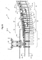
- a part of a conveyor system 10 is shown with a conveyor device 12 according to the invention.
- the conveyor 10 in this example conveys preforms 14 of PET bottles.
- the section of the conveyor system 10 shown comprises a first conveyor line A, in which the preforms 14, for example, between two rails 22 are transported hanging. The transport can take place on the rails 22 indicated by dashed lines over an inclined path under the influence of gravity or with the aid of an air flow channel (both not explicitly shown).
- the preforms 14 are conveyed in the conveyor line A in a loose, disordered stream.
- a second conveying path B is connected to a circulatory conveying device 30 according to the invention of the conveying device 12 according to the invention.
- a further conveyor line C Downstream of the conveyor line B, a further conveyor line C is provided, which in this example is equipped with a further conveyor element 15 of the conveyor device 12 according to the invention.
- an inventive star wheel 16 is provided for the separation of the preforms 14.
- the preforms 14 are transported hanging on their annular collar 20.
- a conveyor line D can be seen, to which the preforms 14 are delivered after their separation by the star wheel 16.
- the conveyor line D is equipped with a further conveying device which has a conveying means 24.
- the further conveying device is a chain conveyor 18, with a conveying means 24, which in the FIG. 2 indicated by a dashed line is shown.
- a conveying means 24 On conveyor 24 terminals 26 are arranged with jaws 28 at a defined distance from each other.
- the preforms 14 are clocked by the star wheel 16 in the terminals 26 of the chain conveyor 18 and clamped in the region of the conveying path D between the jaws 28 of the terminals 26 and transported.
- An engagement of the collar 20 of the preforms 14 by the clamps 26 may be useful for a more stable transport in the area of the conveyor line D, but is not mandatory.
- two circulation-conveying elements 30 according to the invention of the conveying device 12 according to the invention are provided in the conveying path B between the conveying path A and the starwheel 16.
- the two circulating conveyor members 30 are each provided with a circulating endless conveyor 32, wherein their upper runs 33 are arranged parallel to each other and essentially describe the conveyor track with its transport path 34.
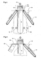
- the circulation conveyors 30 are arranged in the example shown here inclined to the transport path 34, as better from the enlarged, schematic representation of Fig. 3 is apparent.
- the basic circulation levels 36 of the circulation conveyor members 30 include in the example shown here an angle ⁇ of about 50 °. But how is this from the Fig.
- an angle ⁇ in the range of 0 ° (parallel) to 90 ° (perpendicular) between principal orbital plane 36 and transport path 34 may be provided. It is understood that by introducing deflection rollers (not shown) instead of a circulating plane a curved, virtual surface of the endless conveyor 32 of a circulating conveyor member 30 is circulated. In such a case, with principal circulation plane 36, a plane resulting from averaging in the considered delivery section should be designated.
- the endless conveying means 32 of the circulatory conveying members 30 are each driven by means of a drive member 38, which in the example shown here in each case comprises two drive rollers 40.
- the drive rollers 40 are each arranged at the end of the circulation and also serve as deflection rollers. For short conveyor lines, only one drive roller 40 can be provided, and for very long distances more than two drive rollers 40 can be provided.
- the drive rollers 40 are operated synchronously in the usual way, wherein the same drive source (motor) or two separate drive sources can be provided for the two circulation conveyor organs.
- the drive rollers 40 and endless conveyor 32 are coordinated so that the endless conveyor 32 does not slip on the drive rollers 40 even under load.
- drive rollers 40 and endless conveyor 32 can be achieved by an appropriate choice of material for drive rollers 40 and endless conveyor 32 and a skilful embodiment of the same. Also coatings can be here help.
- Examples of a suitable choice of material are drive rollers 40 made of metal with an endless conveyor 32 made of a matched to the metal rubber or a rubber compound. Depending on the metal, both natural rubber and industrially produced rubber can be used. As metals, aluminum-based alloys, steel, and the other alloys known to be used for such purposes may be used. Also plastic rollers in combination with nylon straps are conceivable. It is important that the highest possible coefficient of friction between the drive member 38 and endless conveyor 32 is achieved.
- the endless conveying means 32 may also be roughened or toothed for better support on the rollers on their side facing the rollers.
- Analogous measures can also be provided for the running surfaces of the drive rollers.
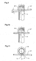
- Another way to prevent slippage of the endless conveyor 32 is the endless conveyor 32 as a link chain 32 '(see. Fig. 6 ) and the drive member 38 as a with the link chain 32 'meshing conveyor wheel 40' to design.
- the endless conveyor 32 With respect to the collar 20 of the object to be transported, in this case with respect to the preforms 14 of PET bottles, the endless conveyor 32 must be selected so that a friction coefficient between collar 20 and endless conveyor 32 adapted to the requirements of the current situation results.
- the appropriate coefficient of friction results primarily from the profile of the conveyor line and the required back pressure. This is the force with which the preforms 14 are transferred to the star wheel 16 in the example shown here.
- the coefficient of friction between the collar 20 and the endless conveyor 32 can in turn be influenced by the material, coating and surface structure of the endless conveyor 32 on its side facing the collar 20. It is also conceivable to coat the collars 20 at least on their underside, wherein such a coating can also be designed as a temporary coating.
- the coefficient of friction is in this case dimensioned such that the objects to be transported, ie in the example shown here, the preforms 14, alone due to the frictional force between endless conveyor means 32 and collar 20 are moved away from the endless conveyor means 32 and at least in a storage section 42 of the conveying path described by the endless conveyor 32, with a corresponding, acting against the transport direction on the preforms 14 resistance the endless conveyor 32 under the collar 20th slip through the preforms 20.
- a transfer area 44 with supporting slots 46, onto which the preforms 14 are pushed on the basis of the dynamic pressure, joins the storage section 42. From this transfer region 44, the preforms 14 are withdrawn by the star wheel 16.
- the support link 46 forms in the transfer area a kind of pair of rails on which the preforms 14 are pushed in front of the star wheel 16. This ensures good guidance of the preforms in the transfer area. As in Fig. 2 shown, the support link 46 extends with its one edge along the transport path, the cover the preforms 14 in the star wheel 16, so that the preforms 14 are well guided on this section of the conveyor line.
- the star wheel 16 To remove the preforms 14, the star wheel 16 a star plate 48 with evenly distributed over the circumference, outwardly projecting fingers 50, which are interconnected by arcuate recesses 52.
- the leading, ie pointing in the direction of transport, arcuate edge 54 of each finger 50 has a narrower radius than the trailing edge 56, wherein the radii smoothly merge into one another.
- the radii are matched to the diameter of the preforms 14 in the region of their collar 20.
- This special design of the star plate 48 makes it possible to promote the preforms 14 not only at a right angle to the star wheel, but as indicated by indicated by dashed lines conveyor axes X and Y, in variable angles to a tangential feed.
- a part of the support link 46 is formed so that it Supporting area with its supporting side, the circumference of the star plate 48 traced at a suitable distance.
- the star wheel 16 is also connected to the conveyor means 24 of the chain conveyor 18 for a synchronized drive, whereby the clocking of the preforms 14 in the chain conveyor 18 is simplified.
- the operative connection is here produced by a gear wheel 60 arranged above the star plate 48 and at a distance to it on a common axis of rotation 58, which meshes with the conveying means 24 of the chain conveyor 18.
- the aim is a problem-free transfer of the objects to be transported from a conveyor line A with less well defined and possibly smaller distance between the objects to be transported upstream of the inventive conveyor 12 on a conveyor line D with a well-defined greater distance downstream of the conveyor 12, in realized here by the chain conveyor 18.
- the chain conveyor 18 For this purpose, it is necessary to accumulate the arriving in loose order objects before their separation by the star wheel 16.
- the conveyor section described by the endless conveyor 32 assumes in its upstream region the incoming in loose stream preforms 14, which are hung on their collar 20 on the endless conveyor means 32 of the conveyor 12.
- the preforms 14 are moved away from the endless conveying means 32 due to the frictional force existing between the endless conveying means 32 and the collar 20.
- In the transfer region 44 acts on the preforms 14 against its transport direction T, a resistor starting from the star wheel 16 a. This resistance is so great that the frictional force between endless conveyor means 32 and collar 20 is overcome and the endless conveying means 32 slip under the collar 20.
- the preforms 14 will be in front of the Star wheel 16 jammed and urged against the star wheel 16 with a sufficiently high dynamic pressure, so that the transfer takes place in the star wheel 16 easily.
- the sufficiently high back pressure is ensured by a correspondingly high speed of the endless conveyor 32.
- the conveyor device 12 designed so that the back pressure is adjustable.
- the conveyor device 12 is equipped with a corresponding control loop R.
- the speed of endless conveyors is primarily regulated. But this also has an influence on the differential speed between withdrawal speed of the star wheel 16 and speed of the endless conveyor 32, and possibly on the length of the jam line.
- a jam section here the area of the transfer area 44 and the jam portion 42 is understood in which jammed, ie in close contact successively located preforms 14 are located.
- sensors S1, S2, S3 are provided for detecting the take-off speed, the speed of the endless conveying means 32 and the length of the jam passage.
- the control loop influences the speed of the endless conveyor.
- the damming, the transfer and the clocking of objects to be transported are improved. This is especially true if the transfer takes place between differently timed conveyor lines, or of a transport section with disorderly, loose stream to a transport section with a predetermined pitch or a predetermined clock.
- a weak point in the suspended transport of preforms 14 or other objects represent changes in the direction of transport, as the objects start to oscillate uncontrollably.
- a change of direction coincides with the transfer from the conveying device 12 according to the invention to the star wheel 16 and with an acceleration from a stowed position.
- a compressed-air nozzle 58 is provided here as a means for pressurizing the preforms 14 with compressed air.
- the distance between the guide rails can be variably adjusted and so on the objects to be transported, for example, on bottles 61, set.
- the guide rails 62 can also be running guide strips (not shown) may be provided, the distance from each other is preferably also adjustable.
- the position with respect to the transport path 34 is preferably adjustable, so that regardless of the objects to be transported the Leitb selected or guide rails 62 approximately in the lower third of the objects to be transported act on them.
- the swing in the transport direction and especially a lifting of the collar 20 from the endless conveyor 32 is arranged by a above the head 63 Rail 64 largely prevented.
- the rail 64 is adjustable in position to the transport path 34 and thus adapt to different head heights.
- preforms 14 and, for example, bottles behave differently during transport.
- the diameter of the neck of the bottle with the collar is relatively small in relation to the diameter of the body, compare in Fig. 4 Contoured with dashed lines contour 61.
- Running bottles 61 on each other this can lead to larger deflections in the region of the collar 20 and the above the collar 20 arranged head 63.
- the bottles in the area of the neck / collar tilt 20 and a manual intervention is necessary.
- this risk is lower.
- the conveying device 12 can also be equipped with an endless conveying means 32 on only one side of the conveying path.
- a support means 66 is provided which, as in the example shown here, as a collar 20 of the preforms 14 to be transported under cross-rail 66 'is formed.
- a plurality of rails 66 ' may be provided one behind the other, or else rails 66' and endless conveyor means 32 may be provided one behind the other as support means 66.
- a support device 66 composed of a plurality of elements 66 ', 32 can be useful, for example, if the transport path 34 has different inclines and / or bends.
- Fig. 6 shows a further embodiment of the inventive conveying device 12, in which, as already described above, the endless conveyor 32 formed by link chains 32 'and the drive members 38 as with the link chain 32' meshing conveyor wheels 40 ' are designed.
- Such a design reliably prevents slippage of the endless conveyor 32.
- For trouble-free transport are on the link chains 32 'laterally in the direction of the collar 20 protruding support members 67 attached, which are provided in the example shown here with a coating 68, which to achieve the desired Friction coefficient between collar 20 and endless conveyor 32 is tuned.
- the orbital plane 36 is parallel to the transport path 34 in this example, ie the angle ⁇ included by both is 0 °.
- FIG. 7 shown embodiment of the inventive conveyor 12 are as in the Fig. 3 to 5
- the round belts 32 "are supported in plastic support rails 70, for which purpose the support rails 70 have a groove 72 formed opposite to the round belts.
- plastic support rails 70 support rails 70 made of metal are also conceivable, the grooves 72 of which are then coated eg with polytetrafluoroethylene (Teflon®) in order to minimize abrasion both for the belts 32 "and for the support rails 70. not shown, may be provided instead of or in addition to the support rails 70.
- Teflon® polytetrafluoroethylene
- the endless conveyor 32 as a flat belt 32 '''is formed.
- the orbital plane 36 realized here is approximately perpendicular to the transport path 34 and therefore encloses an angle ⁇ of approximately 90 ° with this angle ⁇ .
- a further embodiment of the conveyor device 12 according to the invention is shown.
- the conveyor 12 is the same structure as in the FIGS. 1 to 3 illustrated conveyor. But in the example shown here along the conveyor lines A and B side guide strips 62 and also an upper guide rail 64 are provided, as in section also in Fig. 4 were shown.
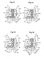
- Fig. 12 Also shown a further embodiment of the inventive star wheel 16.
- the star wheel 16 in this example the same structure as in the FIGS. 1 and 2 illustrated star wheel.
- the starwheel 16 has two star plates 48, 48 'arranged on a common axis of rotation 58 at a distance from each other and acting in parallel on the preforms 14 to be transported.
- the upper, supporting star plates 48 engages with their fingers 50, the collar 20 of the preforms 14 and provides a hanging on the collar 20 transport the same.
- the second or lower, star plate is the supporting star plate 48 '. It engages simultaneously with the supporting star plate 48 laterally in the lower third of the preforms 14 to this and supports them from the side, so that an uncontrolled swinging of the preforms 14 is prevented in the transfer.
- the distance between the star plates 48, 48 ' is adjustable so that it can be adapted to different objects to be transported.
- the star plates 48, 48 ' can be used with the matching contours in coordination with the objects to be transported.
- the supporting star plate 48 'must have a contour other than the supporting star plate 48, so that the fingers 50' of the lower supporting star plate 48 'coincide with the fingers 50 of the upper supporting star plate 48 on the bottles to be withdrawn from the transfer region 44 to be able to intervene.
- star plates 48, 48 ' are not considered solid plates, but e.g. may also be in wheel-like shape, with material recesses for the purpose of weight reduction or in the form of spoked wheels, etc.
- Fig. 13 is a preform 14 approximately at the lowest point of the two fingers 50 provided pocket-like recess 52.
- the preform 14 is by means of of the circulating conveyor 30 is forced into the recess 52 of the star wheel 16 on the back pressure exerted in the transfer area 44 jammed preforms 14.
- arrow R of the star wheel 16
- the leading arcuate edge is pressed with the narrower radius in the direction of rotation R against the preform 14, Fig. 14
- the preform 14 is taken along by the leading edge 54 and the associated finger 50 in the direction of rotation R and withdrawn from the preforms 14 accumulated in a row, Fig.
- the distance of the upper or inner runs 33 of the circulation conveyor members 30, or the one Umlauf devisorgans 30 and the support means 66 is variably adjustable over the transport path described by the endless conveyor 32. This can be realized, for example, by means of deflecting or supporting rollers movable transversely to the conveying path, or supporting rails 70 movable transversely to the conveying path, or else by means of elements 66 ', 32 of a supporting device 66 that are movable transversely to the conveying path.
- the conveying path can be divided into transport areas and storage areas.
- the distance is slightly smaller than the diameter of the objects to be transported in the region of their collar 20 and in the storage areas 42, it is a little bigger.
- slipping of the Endless conveyor 32 prevents under the collar 20 due to a laterally applied clamping action and the objects can only be transported but not jammed.
- Such variable length sections are preferably provided upstream.
- both a transport and a jamming of the objects to be transported is possible.
- the transport takes place due to the frictional force between the endless conveyor 32 and the collar 20, while the endless conveyor 32 slips under the collar 20 in this area and the objects are jammed when a sufficiently large resistance to the objects acts against the transport direction.
- the conveyor device according to the invention brings many advantages when articles to be transported are to be jammed or separated. Further advantages are, for example, that compared with a gravity-based rail conveyor, the back pressure can be produced even without a great incline, thus eliminating the large construction heights. Maintenance work must therefore not be carried out at high altitude. Furthermore, horizontal conveyor lines or conveyor lines can easily be designed with a slight increase without difficulty. In relation to rail conveyor devices which are operated with a compressed air flow, a conveyor device according to the invention with endless conveying means is generally less expensive. With the aid of the conveying device according to the invention, the objects to be transported are well guided in the transfer area.
Claims (17)
- Procédé de convoyage, à l'aide d'un moyen de convoyage sans fin accomplissant une révolution, d'objets présentant un col au-dessus de leur centre de gravité, caractérisé par le fait que les objets (14) à transporter sont suspendus sur le moyen de convoyage sans fin (32, 32', 32", 32"') par au moins un côté de leurs cols (20), au moins sur une zone d'accumulation (42) d'un trajet de convoyage décrit par ledit moyen de convoyage sans fin (32, 32', 32", 32"'), et sont soutenus par ledit moyen en opposition à la force de gravité, sachant que le moyen de convoyage sans fin (32, 32', 32", 32"') assure une poursuite du mouvement des objets (14) sous l'effet d'une force de frottement s'exerçant entre ledit moyen de convoyage sans fin (32, 32', 32", 32"') et les cols (20), et sachant que ladite force de frottement est ajustée de façon telle qu'en présence d'une résistance correspondante, agissant à l'encontre de la direction de transport (T) sur un objet (14) à transporter, le moyen de convoyage sans fin (32, 32', 32", 32"') ripe au-dessous du col (20) dudit objet (14) à transporter ; et sachant que la force de frottement entre le col (20) et les moyens de convoyage sans fin (32, 32', 32", 32"') est ajustée, en particulier, grâce au choix d'un matériau adéquat destiné au moyen de convoyage sans fin (32, 32', 32", 32"') prévu au minimum, vis-à-vis du matériau du col (20) de l'objet à transporter, et/ou d'un angle d'inclinaison correspondant (β) du trajet de convoyage, et/ou d'un revêtement correspondant (68, 68') du moyen de convoyage sans fin (32, 32', 32", 32"') prévu au minimum, et/ou du col (20).
- Procédé selon la revendication 1, caractérisé par le fait que les objets (14) à transporter sont transférés à un organe de convoyage (15, 16) disposé en aval, ou à un dispositif de convoyage (18) supplémentaire et, à cette fin, la puissance de convoyage du moyen de convoyage sans fin (32, 32', 32", 32"') prévu au minimum est réglée supérieure à la vitesse d'extraction avec laquelle les objets (14) sont extraits par l'organe de convoyage (15, 16), de sorte que lesdits objets (14) sont emmagasinés dans la zone d'accumulation (42), en formant un trajet d'accumulation, et sont sollicités par une pression d'accumulation.
- Procédé selon la revendication 2, caractérisé par le fait que la pression d'accumulation ou la longueur du trajet d'accumulation est réglée par réglage de la vitesse du moyen de convoyage sans fin (32, 32', 32", 32"') prévu au minimum.
- Procédé selon la revendication 3, caractérisé par le fait qu'une vitesse différentielle entre la vitesse d'extraction et la vitesse du moyen de convoyage sans fin (32, 32', 32", 32"') prévu au minimum, et/ou la longueur du trajet d'accumulation, est ajustée à l'aide d'un circuit régulateur (R) et il s'opère notamment, à cet effet, une détection de la vitesse du moyen de convoyage sans fin (32, 32', 32", 32"') prévu au minimum et/ou de la vitesse d'extraction et/ou de la longueur du trajet d'accumulation.
- Procédé selon l'une des revendications 2 à 4, caractérisé par le fait que, lors du transfert des objets (14) à transporter, jusque sur l'organe de convoyage (15, 16) disposé en aval ou jusque sur le dispositif de convoyage (18) supplémentaire, lesdits objets (14) sont sollicités par de l'air comprimé et sont ainsi stabilisés dans leur position.
- Dispositif de convoyage pour la mise en oeuvre du procédé selon les revendications 1-5, comprenant un moyen de convoyage sans fin accomplissant une révolution et mené, à l'aide d'organes d'entraînement, en vue de convoyer des objets présentant un col au-dessus de leur centre de gravité, caractérisé par le fait que le moyen de convoyage sans fin (32, 32', 32", 32"') et l'organe d'entraînement (38, 40, 40', 40"') sont mutuellement coordonnés de manière à empêcher un ripage dudit moyen de convoyage sans fin (32, 32', 32", 32"') sur ledit organe d'entraînement (38, 40, 40', 40"') sous l'effet d'une charge ; et, en conséquence, par le fait que les objets (14) à transporter, soutenus par le moyen de convoyage sans fin (32, 32', 32", 32''') en opposition à la force de gravité et en suspension par au moins un côté de leurs cols (20), peuvent être transportés dans au moins une zone d'accumulation (42) d'un trajet de convoyage décrit par le moyen de convoyage sans fin (32, 32', 32", 32"'), sans être soumis à aucun effet de coincement, sachant que la poursuite du mouvement des objets (14) à transporter a lieu sous l'action de la force de frottement s'exerçant entre le col (20) et le moyen de convoyage sans fin (32, 32', 32", 32"'), et que ladite force de frottement est en particulier réglable sur une force de transfert nécessaire par laquelle lesdits objets (14) à transporter doivent être transférés jusque sur un organe de convoyage (15, 16) situé davantage en aval, ou bien jusque sur un dispositif de convoyage (18) supplémentaire.
- Dispositif de convoyage selon la revendication 6, caractérisé par le fait que, en vue d'éviter le ripage du moyen de convoyage sans fin (32, 32', 32", 32"') sur l'organe d'entraînement (38, 40, 40', 40"'), ledit moyen de convoyage sans fin (32, 32', 32", 32"') consiste en un matériau correspondant coordonné avec le matériau dudit organe d'entraînement (38, 40, 40"'), et/ou ledit moyen de convoyage sans fin (32, 32', 32", 32"') et/ou ledit organe d'entraînement (38, 40, 40"') présentent un revêtement correspondant, ou bien une chaîne articulée (32') est prévue en tant que moyen de convoyage sans fin (32) et une roue convoyeuse (40'), en prise d'engrènement avec ladite chaîne articulée (32'), est prévue en tant qu'organe d'entraînement (38).
- Dispositif de convoyage selon la revendication 6 ou 7, caractérisé par la présence, du côté tourné à l'opposé du moyen de convoyage sans fin (32, 32', 32", 32"'), d'un système d'appui (66) matérialisé, de préférence, par un ou plusieurs rail(s) d'appui (66') agencés en succession, et/ou par au moins un moyen supplémentaire de convoyage sans fin (32, 32', 32", 32"'), ledit moyen ou lesdits moyens de convoyage sans fin (32, 32', 32", 32"') étant de réalisation analogue à celle du premier moyen de convoyage sans fin (32, 32', 32", 32"').
- Dispositif de convoyage selon la revendication 8, caractérisé par le fait que la distance comprise entre le moyen de convoyage sans fin (32, 32', 32", 32"') et le système d'appui (66) est réglable, de préférence variable sur le trajet de convoyage.
- Dispositif de convoyage selon la revendication 6, caractérisé par le fait que la force de frottement, entre le moyen de convoyage sans fin (32, 32', 32", 32"') et le col (20), peut être réglée grâce à un choix correspondant du matériau dudit moyen de convoyage sans fin (32, 32', 32", 32"') et/ou grâce à un angle d'inclinaison correspondant (β) du trajet de convoyage, et/ou grâce à un revêtement correspondant (68) dudit moyen de convoyage sans fin (32, 32', 32", 32"') et/ou dudit col (20).
- Dispositif de convoyage selon l'une des revendications 6 à 10, caractérisé par le fait que la vitesse du moyen ou des moyens de convoyage sans fin (32, 32', 32", 32"') peut être régulée.
- Dispositif de convoyage selon la revendication 11, caractérisé par la présence, pour la régulation de la vitesse, d'un circuit régulateur (R) et d'un ou plusieurs capteur(s) (S1, S2, S3) en vue de détecter au moins l'un des paramètres suivants : la vitesse du moyen de convoyage sans fin (32, 32', 32", 32"') prévu au minimum, et/ou la vitesse d'extraction, et/ou la longueur du trajet d'accumulation.
- Dispositif de convoyage selon l'une des revendications 6 à 12, caractérisé par le fait que le plan de révolution (36) du moyen ou des moyens de convoyage sans fin (32, 32', 32", 32"'), et une trajectoire de transport (34) décrite par le trajet de transport, décrivent un angle (α) situé dans la plage comprise entre environ 0° et 90°.
- Dispositif de convoyage selon l'une des revendications 6 à 13, caractérisé par la présence, dans une zone de transfert (44) dans laquelle il est prévu de transférer les objets (14) à transporter jusque sur l'organe de convoyage (15, 16) disposé en aval ou jusque sur un dispositif de convoyage (18) supplémentaire, de moyens (59) à l'aide desquels lesdits objets à transporter peuvent être stabilisés, plus particulièrement, de préférence, par de l'air comprimé.
- Dispositif de convoyage selon l'une des revendications 6 à 14, caractérisé par la présence, en tant qu'organe supplémentaire de convoyage (15) du dispositif de convoyage (12), d'une roue en étoile (16) qui est destinée à l'insertion cadencée dans un dispositif de convoyage (18) situé davantage en aval, se trouve dans la continuité directe de la zone de transfert (44) et comporte, en vue d'un transfert contrôlé, deux disques en étoile (48, 48') agencés à distance mutuelle sur un axe commun de rotation (58) et agissant, en simultanéité, sur les objets (14) à transporter.
- Dispositif de convoyage selon la revendication 15, caractérisé par le fait que les disques en étoile (48, 48') sont pourvus de doigts (50, 50') qui sont répartis uniformément sur le pourtour, font saillie vers l'extérieur et sont reliés mutuellement par des échancrures (52) en arc de cercle, du type poches affectées à la réception des objets (14) à transporter, sachant que notamment le bord d'attaque (54) en arc de cercle de chaque doigt (50, 50'), pointant dans la direction de rotation (R), possède un rayon plus étroit qu'un bord de fuite (56), les rayons fusionnant d'un trait l'un dans l'autre.
- Dispositif de convoyage selon la revendication 15 ou 16, caractérisé par le fait que la roue en étoile (16) est en liaison opérante avec un moyen de convoyage (24) d'un dispositif de convoyage (18) situé dans la continuité directe en aval.
Applications Claiming Priority (2)
| Application Number | Priority Date | Filing Date | Title |
|---|---|---|---|
| CH1202004 | 2004-01-28 | ||
| CH1202004 | 2004-01-28 |
Publications (2)
| Publication Number | Publication Date |
|---|---|
| EP1559663A1 EP1559663A1 (fr) | 2005-08-03 |
| EP1559663B1 true EP1559663B1 (fr) | 2008-10-29 |
Family
ID=34638007
Family Applications (1)
| Application Number | Title | Priority Date | Filing Date |
|---|---|---|---|
| EP05001533A Not-in-force EP1559663B1 (fr) | 2004-01-28 | 2005-01-26 | Procédé et convoyeur destiné au transport d'objets munis d'un col |
Country Status (4)
| Country | Link |
|---|---|
| EP (1) | EP1559663B1 (fr) |
| AT (1) | ATE412594T1 (fr) |
| DE (1) | DE502005005769D1 (fr) |
| ES (1) | ES2315744T3 (fr) |
Families Citing this family (15)
| Publication number | Priority date | Publication date | Assignee | Title |
|---|---|---|---|---|
| JP2000162215A (ja) * | 1998-11-30 | 2000-06-16 | Ids:Kk | 検体処理管体およびその搬送システム |
| DE102005048358A1 (de) | 2004-11-30 | 2006-08-24 | Sig Technology Ltd. | Verfahren und Vorrichtung zum Transport von Vorformlingen |
| CN102460179B (zh) * | 2009-06-24 | 2014-07-16 | 株式会社Afc | 采血管储料器及采血管准备装置 |
| DE102010007401A1 (de) | 2010-02-03 | 2011-08-04 | Kärcher Futuretech GmbH, 71364 | Vorrichtung und Verfahren zum automatisierten Formen und Abfüllen von Behältern |
| FR2956652B1 (fr) | 2010-02-25 | 2015-12-11 | Sidel Participations | Installation de convoyage d'articles en materiau thermoplastique |
| CN102009845B (zh) * | 2010-06-28 | 2013-03-06 | 楚天科技股份有限公司 | 用于瓶体的输送装置 |
| CN102009838B (zh) * | 2010-06-28 | 2013-03-06 | 楚天科技股份有限公司 | 一种瓶体输送组件 |
| CN102009836B (zh) * | 2010-06-28 | 2013-03-06 | 楚天科技股份有限公司 | 一种瓶体传送组件 |
| CN102009837A (zh) * | 2010-06-28 | 2011-04-13 | 楚天科技股份有限公司 | 一种瓶体输送装置 |
| DE102011050843A1 (de) * | 2011-06-03 | 2012-12-06 | Nov Hau Ag Engineering | Verfahren und Vorrichtung zum Transport von Gegenständen zu einer Station |
| ITMO20130182A1 (it) * | 2013-06-24 | 2014-12-25 | Sacmi | Sistema per trasportare oggetti |
| CN103640207B (zh) * | 2013-10-29 | 2015-11-18 | 广州达意隆包装机械股份有限公司 | 一种加温链结构 |
| CN104665843A (zh) * | 2013-11-26 | 2015-06-03 | 湖南千山医疗器械有限公司 | 一种采血管自动选管方法及设备 |
| EP3453648B1 (fr) * | 2017-09-07 | 2024-04-03 | M. Tanner AG | Dispositif d'alimentation |
| CN111115195A (zh) * | 2019-12-30 | 2020-05-08 | 广州创惠信息科技有限公司 | 一种导直装置及分拣上架机 |
Family Cites Families (12)
| Publication number | Priority date | Publication date | Assignee | Title |
|---|---|---|---|---|
| US4223778A (en) * | 1978-05-12 | 1980-09-23 | Owens-Illinois, Inc. | Parison handling assemblies and methods for handling parisons |
| US4724035A (en) * | 1985-03-29 | 1988-02-09 | American National Can Company | Apparatus for applying base cups to bottles |
| EP0452857A1 (fr) * | 1990-04-16 | 1991-10-23 | Aidlin Automation Corporation | Appareil pour aligner et amener des objets cylindriques |
| NL9001589A (nl) * | 1990-07-12 | 1992-02-03 | Smit Gerardus | Transportinrichting voor flessen. |
| US5501552A (en) * | 1994-04-29 | 1996-03-26 | Goldco Industries, Inc. | Conveying system for unstable articles having a neck ring |
| US5553698A (en) * | 1994-12-28 | 1996-09-10 | J And J Container Handling Systems | Conveyor belt apparatus for bottles |
| US6109426A (en) * | 1996-11-13 | 2000-08-29 | Simplimatic Engineering Company | Oriented bottle conveyor |
| FR2800361B1 (fr) * | 1999-10-29 | 2001-12-07 | Serac Group | Installation de transfert de recipients comportant un organe de deviation |
| GB9928927D0 (en) * | 1999-12-08 | 2000-02-02 | Central Bottling International | Handling apparatus for use in a bottling plant to handle bottles with neck rings |
| FR2805252B1 (fr) * | 2000-02-21 | 2002-06-28 | Sidel Sa | Dispositif de transfert de recipients comportant une roue de guidage a geometrie variable |
| US6732487B2 (en) * | 2001-11-20 | 2004-05-11 | Tetra Laval Holdings & Finance, S.A. | Post processing closure cap application |
| EP1494943B1 (fr) * | 2002-04-16 | 2006-06-21 | Amcor Limited | Procede et convoyeur destine au transport de contenants suspendus et procede de fabrication et de transport de contenants |
-
2005
- 2005-01-26 EP EP05001533A patent/EP1559663B1/fr not_active Not-in-force
- 2005-01-26 ES ES05001533T patent/ES2315744T3/es active Active
- 2005-01-26 AT AT05001533T patent/ATE412594T1/de not_active IP Right Cessation
- 2005-01-26 DE DE502005005769T patent/DE502005005769D1/de active Active
Also Published As
| Publication number | Publication date |
|---|---|
| ES2315744T3 (es) | 2009-04-01 |
| EP1559663A1 (fr) | 2005-08-03 |
| DE502005005769D1 (de) | 2008-12-11 |
| ATE412594T1 (de) | 2008-11-15 |
Similar Documents
| Publication | Publication Date | Title |
|---|---|---|
| EP1559663B1 (fr) | Procédé et convoyeur destiné au transport d'objets munis d'un col | |
| EP0912426B1 (fr) | Procede de transport suspendu de recipients et dispositif approprie pour mettre ledit procede en oeuvre | |
| EP3115322B1 (fr) | Procede et dispositif destines a la depalettisation de pneus | |
| DE2643709A1 (de) | Sortiervorrichtung fuer ungeordnet verteiltes stueckgut | |
| EP2088099B1 (fr) | Dispositif de transport destiné au transport vertical de marchandises au détail | |
| WO2007093253A1 (fr) | Dispositif pour sortir des objets les uns des autres | |
| DE1815317B2 (de) | Foerderanordnung fuer den transport von filterstaeben, zigaretten oder anderen stabfoermigen artikeln der tabakverarbeitenden industrie | |
| EP0608861A2 (fr) | Procédé et dispositif pour alimenter des objets sensibles dans une machine de traitement | |
| DE19510649A1 (de) | Transportvorrichtung | |
| EP0771754B1 (fr) | Dispositif pour assembler des produits plats | |
| EP2723659B1 (fr) | Dispositif et procédé permettant de grouper des objets | |
| DE3633617A1 (de) | Verfahren und vorrichtung zum verarbeiten von druckprodukten | |
| EP2818436B1 (fr) | Dispositif de séparation d'objets | |
| CH711791A1 (de) | Fördersystem. | |
| AT500087A1 (de) | Vereinzelungseinrichtung für langteile sowie vorrichtung zum transport derselben | |
| EP3277607B1 (fr) | Procédé et système de guidage pour le transport de récipients ou de composants de récipients dans des installations industrielles pour la fabrication de récipients et/ou le remplissage de produit | |
| EP0193878B1 (fr) | Appareil pour transformer un courant large de bouteilles en un courant de sortie à file unique | |
| DE2941456A1 (de) | Zufuhreinrichtung fuer gegenstaende | |
| EP1059256B9 (fr) | Dispositif pour corriger la position d'objects plats arrivant en formation imbriquée | |
| EP0419447B1 (fr) | Méthode et dispositif pour décalaminage de barres d'acier rondes | |
| DE10317417B4 (de) | Vereinzelungs- und Fördervorrichtung | |
| DE10112333A1 (de) | Stückgut-Stetigfördereinrichtung | |
| EP1538115B1 (fr) | Méthode pour le transport de produits | |
| DE19839664B4 (de) | Transportanlage für Langteile | |
| EP2243729A2 (fr) | Dispositif de transport et procédé d'introduction de récipients de liquides dans une machine d'emballage |
Legal Events
| Date | Code | Title | Description |
|---|---|---|---|
| PUAI | Public reference made under article 153(3) epc to a published international application that has entered the european phase |
Free format text: ORIGINAL CODE: 0009012 |
|
| AK | Designated contracting states |
Kind code of ref document: A1 Designated state(s): AT BE BG CH CY CZ DE DK EE ES FI FR GB GR HU IE IS IT LI LT LU MC NL PL PT RO SE SI SK TR |
|
| AX | Request for extension of the european patent |
Extension state: AL BA HR LV MK YU |
|
| 17P | Request for examination filed |
Effective date: 20060203 |
|
| AKX | Designation fees paid |
Designated state(s): AT BE BG CH CY CZ DE DK EE ES FI FR GB GR HU IE IS IT LI LT LU MC NL PL PT RO SE SI SK TR |
|
| 17Q | First examination report despatched |
Effective date: 20070226 |
|
| 17Q | First examination report despatched |
Effective date: 20070226 |
|
| GRAP | Despatch of communication of intention to grant a patent |
Free format text: ORIGINAL CODE: EPIDOSNIGR1 |
|
| GRAS | Grant fee paid |
Free format text: ORIGINAL CODE: EPIDOSNIGR3 |
|
| GRAA | (expected) grant |
Free format text: ORIGINAL CODE: 0009210 |
|
| AK | Designated contracting states |
Kind code of ref document: B1 Designated state(s): AT BE BG CH CY CZ DE DK EE ES FI FR GB GR HU IE IS IT LI LT LU MC NL PL PT RO SE SI SK TR |
|
| REG | Reference to a national code |
Ref country code: GB Ref legal event code: FG4D Free format text: NOT ENGLISH |
|
| REG | Reference to a national code |
Ref country code: CH Ref legal event code: EP Ref country code: CH Ref legal event code: NV Representative=s name: RENTSCH & PARTNER |
|
| REG | Reference to a national code |
Ref country code: IE Ref legal event code: FG4D Free format text: LANGUAGE OF EP DOCUMENT: GERMAN |
|
| REF | Corresponds to: |
Ref document number: 502005005769 Country of ref document: DE Date of ref document: 20081211 Kind code of ref document: P |
|
| NLV1 | Nl: lapsed or annulled due to failure to fulfill the requirements of art. 29p and 29m of the patents act | ||
| REG | Reference to a national code |
Ref country code: ES Ref legal event code: FG2A Ref document number: 2315744 Country of ref document: ES Kind code of ref document: T3 |
|
| LTIE | Lt: invalidation of european patent or patent extension |
Effective date: 20081029 |
|
| PG25 | Lapsed in a contracting state [announced via postgrant information from national office to epo] |
Ref country code: LT Free format text: LAPSE BECAUSE OF FAILURE TO SUBMIT A TRANSLATION OF THE DESCRIPTION OR TO PAY THE FEE WITHIN THE PRESCRIBED TIME-LIMIT Effective date: 20081029 Ref country code: BG Free format text: LAPSE BECAUSE OF FAILURE TO SUBMIT A TRANSLATION OF THE DESCRIPTION OR TO PAY THE FEE WITHIN THE PRESCRIBED TIME-LIMIT Effective date: 20090129 |
|
| PG25 | Lapsed in a contracting state [announced via postgrant information from national office to epo] |
Ref country code: NL Free format text: LAPSE BECAUSE OF FAILURE TO SUBMIT A TRANSLATION OF THE DESCRIPTION OR TO PAY THE FEE WITHIN THE PRESCRIBED TIME-LIMIT Effective date: 20081029 Ref country code: PL Free format text: LAPSE BECAUSE OF FAILURE TO SUBMIT A TRANSLATION OF THE DESCRIPTION OR TO PAY THE FEE WITHIN THE PRESCRIBED TIME-LIMIT Effective date: 20081029 Ref country code: FI Free format text: LAPSE BECAUSE OF FAILURE TO SUBMIT A TRANSLATION OF THE DESCRIPTION OR TO PAY THE FEE WITHIN THE PRESCRIBED TIME-LIMIT Effective date: 20081029 Ref country code: PT Free format text: LAPSE BECAUSE OF FAILURE TO SUBMIT A TRANSLATION OF THE DESCRIPTION OR TO PAY THE FEE WITHIN THE PRESCRIBED TIME-LIMIT Effective date: 20090330 Ref country code: SI Free format text: LAPSE BECAUSE OF FAILURE TO SUBMIT A TRANSLATION OF THE DESCRIPTION OR TO PAY THE FEE WITHIN THE PRESCRIBED TIME-LIMIT Effective date: 20081029 Ref country code: IS Free format text: LAPSE BECAUSE OF FAILURE TO SUBMIT A TRANSLATION OF THE DESCRIPTION OR TO PAY THE FEE WITHIN THE PRESCRIBED TIME-LIMIT Effective date: 20090228 |
|
| REG | Reference to a national code |
Ref country code: IE Ref legal event code: FD4D |
|
| PG25 | Lapsed in a contracting state [announced via postgrant information from national office to epo] |
Ref country code: RO Free format text: LAPSE BECAUSE OF FAILURE TO SUBMIT A TRANSLATION OF THE DESCRIPTION OR TO PAY THE FEE WITHIN THE PRESCRIBED TIME-LIMIT Effective date: 20081029 Ref country code: IE Free format text: LAPSE BECAUSE OF FAILURE TO SUBMIT A TRANSLATION OF THE DESCRIPTION OR TO PAY THE FEE WITHIN THE PRESCRIBED TIME-LIMIT Effective date: 20081029 Ref country code: DK Free format text: LAPSE BECAUSE OF FAILURE TO SUBMIT A TRANSLATION OF THE DESCRIPTION OR TO PAY THE FEE WITHIN THE PRESCRIBED TIME-LIMIT Effective date: 20081029 Ref country code: EE Free format text: LAPSE BECAUSE OF FAILURE TO SUBMIT A TRANSLATION OF THE DESCRIPTION OR TO PAY THE FEE WITHIN THE PRESCRIBED TIME-LIMIT Effective date: 20081029 |
|
| PG25 | Lapsed in a contracting state [announced via postgrant information from national office to epo] |
Ref country code: SE Free format text: LAPSE BECAUSE OF FAILURE TO SUBMIT A TRANSLATION OF THE DESCRIPTION OR TO PAY THE FEE WITHIN THE PRESCRIBED TIME-LIMIT Effective date: 20090129 Ref country code: MC Free format text: LAPSE BECAUSE OF NON-PAYMENT OF DUE FEES Effective date: 20090131 Ref country code: CZ Free format text: LAPSE BECAUSE OF FAILURE TO SUBMIT A TRANSLATION OF THE DESCRIPTION OR TO PAY THE FEE WITHIN THE PRESCRIBED TIME-LIMIT Effective date: 20081029 |
|
| PLBE | No opposition filed within time limit |
Free format text: ORIGINAL CODE: 0009261 |
|
| STAA | Information on the status of an ep patent application or granted ep patent |
Free format text: STATUS: NO OPPOSITION FILED WITHIN TIME LIMIT |
|
| PG25 | Lapsed in a contracting state [announced via postgrant information from national office to epo] |
Ref country code: SK Free format text: LAPSE BECAUSE OF FAILURE TO SUBMIT A TRANSLATION OF THE DESCRIPTION OR TO PAY THE FEE WITHIN THE PRESCRIBED TIME-LIMIT Effective date: 20081029 |
|
| 26N | No opposition filed |
Effective date: 20090730 |
|
| PG25 | Lapsed in a contracting state [announced via postgrant information from national office to epo] |
Ref country code: BE Free format text: LAPSE BECAUSE OF NON-PAYMENT OF DUE FEES Effective date: 20090131 |
|
| PGFP | Annual fee paid to national office [announced via postgrant information from national office to epo] |
Ref country code: ES Payment date: 20100125 Year of fee payment: 6 |
|
| PGFP | Annual fee paid to national office [announced via postgrant information from national office to epo] |
Ref country code: FR Payment date: 20100223 Year of fee payment: 6 Ref country code: IT Payment date: 20100123 Year of fee payment: 6 |
|
| PGFP | Annual fee paid to national office [announced via postgrant information from national office to epo] |
Ref country code: AT Payment date: 20100114 Year of fee payment: 6 Ref country code: GB Payment date: 20100121 Year of fee payment: 6 |
|
| PG25 | Lapsed in a contracting state [announced via postgrant information from national office to epo] |
Ref country code: GR Free format text: LAPSE BECAUSE OF FAILURE TO SUBMIT A TRANSLATION OF THE DESCRIPTION OR TO PAY THE FEE WITHIN THE PRESCRIBED TIME-LIMIT Effective date: 20090130 |
|
| PG25 | Lapsed in a contracting state [announced via postgrant information from national office to epo] |
Ref country code: LU Free format text: LAPSE BECAUSE OF NON-PAYMENT OF DUE FEES Effective date: 20090126 |
|
| PG25 | Lapsed in a contracting state [announced via postgrant information from national office to epo] |
Ref country code: HU Free format text: LAPSE BECAUSE OF FAILURE TO SUBMIT A TRANSLATION OF THE DESCRIPTION OR TO PAY THE FEE WITHIN THE PRESCRIBED TIME-LIMIT Effective date: 20090430 |
|
| REG | Reference to a national code |
Ref country code: CH Ref legal event code: PFA Owner name: FERAG AG Free format text: FERAG AG#ZUERICHSTRASSE 74#8340 HINWIL (CH) -TRANSFER TO- FERAG AG#ZUERICHSTRASSE 74#8340 HINWIL (CH) |
|
| PG25 | Lapsed in a contracting state [announced via postgrant information from national office to epo] |
Ref country code: TR Free format text: LAPSE BECAUSE OF FAILURE TO SUBMIT A TRANSLATION OF THE DESCRIPTION OR TO PAY THE FEE WITHIN THE PRESCRIBED TIME-LIMIT Effective date: 20081029 |
|
| GBPC | Gb: european patent ceased through non-payment of renewal fee |
Effective date: 20110126 |
|
| PG25 | Lapsed in a contracting state [announced via postgrant information from national office to epo] |
Ref country code: CY Free format text: LAPSE BECAUSE OF FAILURE TO SUBMIT A TRANSLATION OF THE DESCRIPTION OR TO PAY THE FEE WITHIN THE PRESCRIBED TIME-LIMIT Effective date: 20081029 |
|
| REG | Reference to a national code |
Ref country code: FR Ref legal event code: ST Effective date: 20110930 |
|
| PG25 | Lapsed in a contracting state [announced via postgrant information from national office to epo] |
Ref country code: FR Free format text: LAPSE BECAUSE OF NON-PAYMENT OF DUE FEES Effective date: 20110131 |
|
| PG25 | Lapsed in a contracting state [announced via postgrant information from national office to epo] |
Ref country code: AT Free format text: LAPSE BECAUSE OF NON-PAYMENT OF DUE FEES Effective date: 20110126 Ref country code: GB Free format text: LAPSE BECAUSE OF NON-PAYMENT OF DUE FEES Effective date: 20110126 |
|
| PG25 | Lapsed in a contracting state [announced via postgrant information from national office to epo] |
Ref country code: IT Free format text: LAPSE BECAUSE OF NON-PAYMENT OF DUE FEES Effective date: 20110126 |
|
| REG | Reference to a national code |
Ref country code: ES Ref legal event code: FD2A Effective date: 20120220 |
|
| PG25 | Lapsed in a contracting state [announced via postgrant information from national office to epo] |
Ref country code: ES Free format text: LAPSE BECAUSE OF NON-PAYMENT OF DUE FEES Effective date: 20110127 |
|
| PGFP | Annual fee paid to national office [announced via postgrant information from national office to epo] |
Ref country code: DE Payment date: 20190123 Year of fee payment: 15 |
|
| PGFP | Annual fee paid to national office [announced via postgrant information from national office to epo] |
Ref country code: CH Payment date: 20190403 Year of fee payment: 15 |
|
| REG | Reference to a national code |
Ref country code: DE Ref legal event code: R119 Ref document number: 502005005769 Country of ref document: DE |
|
| REG | Reference to a national code |
Ref country code: CH Ref legal event code: PL |
|
| PG25 | Lapsed in a contracting state [announced via postgrant information from national office to epo] |
Ref country code: DE Free format text: LAPSE BECAUSE OF NON-PAYMENT OF DUE FEES Effective date: 20200801 |
|
| PG25 | Lapsed in a contracting state [announced via postgrant information from national office to epo] |
Ref country code: CH Free format text: LAPSE BECAUSE OF NON-PAYMENT OF DUE FEES Effective date: 20200131 Ref country code: LI Free format text: LAPSE BECAUSE OF NON-PAYMENT OF DUE FEES Effective date: 20200131 |