EP1538115B1 - Méthode pour le transport de produits - Google Patents
Méthode pour le transport de produits Download PDFInfo
- Publication number
- EP1538115B1 EP1538115B1 EP04027497A EP04027497A EP1538115B1 EP 1538115 B1 EP1538115 B1 EP 1538115B1 EP 04027497 A EP04027497 A EP 04027497A EP 04027497 A EP04027497 A EP 04027497A EP 1538115 B1 EP1538115 B1 EP 1538115B1
- Authority
- EP
- European Patent Office
- Prior art keywords
- conveyor
- products
- conveying
- speed
- section
- Prior art date
- Legal status (The legal status is an assumption and is not a legal conclusion. Google has not performed a legal analysis and makes no representation as to the accuracy of the status listed.)
- Expired - Lifetime
Links
- 238000000034 method Methods 0.000 title claims description 14
- 230000006978 adaptation Effects 0.000 claims description 2
- 230000002441 reversible effect Effects 0.000 abstract description 2
- 230000000717 retained effect Effects 0.000 abstract 1
- 238000009825 accumulation Methods 0.000 description 5
- 238000004806 packaging method and process Methods 0.000 description 3
- 235000015895 biscuits Nutrition 0.000 description 2
- 230000000694 effects Effects 0.000 description 2
- 238000004519 manufacturing process Methods 0.000 description 2
- 230000007704 transition Effects 0.000 description 2
- 230000001419 dependent effect Effects 0.000 description 1
- 238000010586 diagram Methods 0.000 description 1
- 238000011143 downstream manufacturing Methods 0.000 description 1
- 235000013305 food Nutrition 0.000 description 1
- 230000000630 rising effect Effects 0.000 description 1
- 238000011144 upstream manufacturing Methods 0.000 description 1
Images


Classifications
-
- B—PERFORMING OPERATIONS; TRANSPORTING
- B65—CONVEYING; PACKING; STORING; HANDLING THIN OR FILAMENTARY MATERIAL
- B65G—TRANSPORT OR STORAGE DEVICES, e.g. CONVEYORS FOR LOADING OR TIPPING, SHOP CONVEYOR SYSTEMS OR PNEUMATIC TUBE CONVEYORS
- B65G47/00—Article or material-handling devices associated with conveyors; Methods employing such devices
- B65G47/22—Devices influencing the relative position or the attitude of articles during transit by conveyors
- B65G47/26—Devices influencing the relative position or the attitude of articles during transit by conveyors arranging the articles, e.g. varying spacing between individual articles
- B65G47/30—Devices influencing the relative position or the attitude of articles during transit by conveyors arranging the articles, e.g. varying spacing between individual articles during transit by a series of conveyors
-
- B—PERFORMING OPERATIONS; TRANSPORTING
- B65—CONVEYING; PACKING; STORING; HANDLING THIN OR FILAMENTARY MATERIAL
- B65G—TRANSPORT OR STORAGE DEVICES, e.g. CONVEYORS FOR LOADING OR TIPPING, SHOP CONVEYOR SYSTEMS OR PNEUMATIC TUBE CONVEYORS
- B65G13/00—Roller-ways
- B65G13/075—Braking means
-
- B—PERFORMING OPERATIONS; TRANSPORTING
- B65—CONVEYING; PACKING; STORING; HANDLING THIN OR FILAMENTARY MATERIAL
- B65G—TRANSPORT OR STORAGE DEVICES, e.g. CONVEYORS FOR LOADING OR TIPPING, SHOP CONVEYOR SYSTEMS OR PNEUMATIC TUBE CONVEYORS
- B65G21/00—Supporting or protective framework or housings for endless load-carriers or traction elements of belt or chain conveyors
- B65G21/10—Supporting or protective framework or housings for endless load-carriers or traction elements of belt or chain conveyors movable, or having interchangeable or relatively movable parts; Devices for moving framework or parts thereof
- B65G21/14—Supporting or protective framework or housings for endless load-carriers or traction elements of belt or chain conveyors movable, or having interchangeable or relatively movable parts; Devices for moving framework or parts thereof to allow adjustment of length or configuration of load-carrier or traction element
-
- B—PERFORMING OPERATIONS; TRANSPORTING
- B65—CONVEYING; PACKING; STORING; HANDLING THIN OR FILAMENTARY MATERIAL
- B65G—TRANSPORT OR STORAGE DEVICES, e.g. CONVEYORS FOR LOADING OR TIPPING, SHOP CONVEYOR SYSTEMS OR PNEUMATIC TUBE CONVEYORS
- B65G47/00—Article or material-handling devices associated with conveyors; Methods employing such devices
- B65G47/22—Devices influencing the relative position or the attitude of articles during transit by conveyors
- B65G47/26—Devices influencing the relative position or the attitude of articles during transit by conveyors arranging the articles, e.g. varying spacing between individual articles
- B65G47/30—Devices influencing the relative position or the attitude of articles during transit by conveyors arranging the articles, e.g. varying spacing between individual articles during transit by a series of conveyors
- B65G47/31—Devices influencing the relative position or the attitude of articles during transit by conveyors arranging the articles, e.g. varying spacing between individual articles during transit by a series of conveyors by varying the relative speeds of the conveyors forming the series
-
- B—PERFORMING OPERATIONS; TRANSPORTING
- B65—CONVEYING; PACKING; STORING; HANDLING THIN OR FILAMENTARY MATERIAL
- B65G—TRANSPORT OR STORAGE DEVICES, e.g. CONVEYORS FOR LOADING OR TIPPING, SHOP CONVEYOR SYSTEMS OR PNEUMATIC TUBE CONVEYORS
- B65G2201/00—Indexing codes relating to handling devices, e.g. conveyors, characterised by the type of product or load being conveyed or handled
- B65G2201/02—Articles
Definitions
- the invention relates to a method for transporting shingled, dustable products according to the preamble of patent claim 1.
- DE-A-43'11'519, US-5'085'311, US-A-6'062'376 and US-A-6'523'672 disclose devices which have a conveyor for transporting the products as well two parallel
- runway tracks in the form of plates or non-driven roller conveyors.
- the conveyor is adjustable in height relative to the support paths, wherein he raises the products in a raised position on the support webs and thus entrains and is in the lowered state below the support surfaces, so that the products detached from the conveyor rest on the support surfaces and jammed.
- these devices can be used only for lying flat on the conveyor products, which are also sufficiently wide to be supported by the support surfaces. Stacking of the products is not possible.
- US-A-6'168'007 describes a similar functioning device. Here, however, not the conveyor is raised, but the support surfaces stationary in the conveying direction are height adjustable. This device is only suitable for flat-lying products.
- a device which has two horizontally extending and in the conveying direction successively arranged conveyor belts.
- the two conveyor belts on an overlapping area.
- the two conveyor belts form transport surfaces, which are arranged in the same plane.
- a guideway disposed above the transport surface deflects carton blanks from a flat position to an upright position. In this position they are handed over from the first to the second conveyor.
- This device can thus be used only for a particular type of product.
- GB-A-1'042'884 shows a similar device which also has two in the conveying direction overlapping conveyor.
- the second conveyor is arranged lower than the first.
- CH-A-667'258 describes a device for stacking of imprinted printed products.
- the device has two conveyors arranged successively in the conveying direction.
- the relative position of the transition region between the first and second conveyor with respect to the conveyor line and thus the length of the stack to be formed can be selected by means of a sliding carriage.
- the stacking itself takes place in that the second conveyor is arranged lower than the first and that over the conveyors displaceable guide rollers are present. In order to avoid a pressure generated by subsequent products on the stack already formed, the end portion of the second conveyor is formed rising against the stack.
- One out FR-A-2 700 157 Known device for controlling the flow of products transported on conveyors is used to line up products at predefined intervals.
- the products are first conveyed on a conveyor line and then on a storage line, the storage line having a connection area to the conveyor line, in which the products are lifted over the conveyor line.
- the position of the connection region and thus the accumulation end point or accumulation emergence point along the conveying direction can be changed and / or the speed on the accumulator section relative to that on the conveying path can be varied.
- the dynamic pressure can be controlled, so that the device is also suitable for sensitive products or piece goods, such as biscuits.
- both the Delivery as well as the storage section with the exception of the connection area, in a horizontal plane, wherein the storage line is located above the conveyor line.
- the devices described below for transporting and storing products, in particular pressure-sensitive piece goods, can be installed in a wide variety of systems. Preferably, they form the link between a production unit and a packaging or a further processing unit.
- a preferred area of application is the food industry, in particular biscuit production.
- FIGS. 1a and 1b a first embodiment of the device is shown. It has a first conveyor 1 and a second conveyor 2. Of the The first conveyor 1 is used to transport piece-like products along a conveyor line 5. The second conveyor 2 closes downstream in the conveying direction T to the first conveyor 1 and serves for at least temporary storage or storage of the products along a storage path 6.
- the storage section 6 has a Connection area 60, which adjoins the first conveyor section 5. Both conveyors 1, 2 have at least approximately horizontally extending conveying planes 10, 20, wherein the second conveying plane 20 of the second conveyor 2 is higher than the first conveying plane 10 of the first conveyor 1. Thus, the products from the first conveying plane 10 to the second conveying plane 20th Therefore, the connection area 60 increases relative to the conveyor line 5 at.
- the two conveyors 1, 2 run parallel to each other at least in a partial area B. Preferably, they overlap in this region B, wherein the overlap and thus the position of the connection region 60 along the conveying direction T is variable. This can be achieved by means known means, for example by means of sliding carriage, on which deflection rollers at least one of the conveyor 1, 2 are mounted.
- the conveying speed of at least the second conveyor 2 is variable, in particular continuously variable.
- the second conveyor 2 or its control can be designed so that the conveying direction of the second conveyor 2 is also reversible, so that it runs temporarily in the same direction and temporarily in the opposite direction to the conveying direction of the first conveyor 1.
- Each conveyor has a driven drive roller 12, 22 and at least one guide roller 11, 21.
- the position of the second guide rollers 21 along the conveying direction T is variable in position.
- the second conveyor 2 here comprises two parallel and synchronously driven belts, but other embodiments are possible.
- the increase of the connection region 60 and the higher position of the second conveyor 2 can be achieved in different ways.
- the second conveyor 2 can be easily arranged on a higher-mounted frame and arrange its at least one rear guide roller 21 at the desired intermediate height.
- lifting means 3 or ramps of known type are used.
- FIG. 2 shown.
- the products P are transported along the conveying path 5 by both or at least by the first conveyor 1.
- the arrangement can also be reversed.
- the desired storage area of the second conveyor 2 is raised by means of lifting means, not shown here, as shown in the FIG. 2 is shown here and take over the further transport of the products along the storage path 6.
- the position of the connection region 60 and thus the position of the increase of the second conveyor 2 is preferably variable.
- FIG. 3 another variant is shown.
- the first conveyor 1 in turn, an endless plate chain conveyor.
- the second conveyor 2 in turn consists of two synchronously driven part conveyors, which, however, are each here formed by a circulating strand or traction conveyor, which is embedded in grooves 40 of a holding device 4 of the first conveyor 1.
- the products are pushed from the lower level of the first conveying plane 10 to the higher level of the second conveying plane 20 on the rotating strand or traction conveyor.
- FIGS. 4a and 4b a fourth embodiment is shown.
- This example is particularly suitable for the transport of round or cylindrical products P.
- the first conveyor 1 has lateral guides 13 in the form of inclined surfaces, between which the product P is stored.
- the second conveyor 2 for example a plate chain conveyor, is located in the central axis of the first conveyor 1 and has lifting means 3.
- FIG. 4a the position of the second conveyor 2 is shown in a lowered position, the products P are transported by means of the first conveyor 1.
- FIG. 4b If the second conveyor 2 is raised, the product P no longer contacts the first conveyor 1, but is transported or jammed in accordance with the conveying speed of the second conveyor 2.
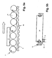
- the FIGS. 5a and 5b show a fifth embodiment.
- the first conveyor 1 is a roller conveyor with individually driven rollers 14. Each roller 14 is individually supported on a frame 16 and connected to a drive 15. The drive 15 may be common to all rollers 14. At least in a portion B of the second runs Conveyor 2 parallel and below the first conveyor 1.
- the second conveyor 2 is for example a belt conveyor or a plate chain conveyor.
- the second conveyor 2 is provided with means for lifting it in the connection area 60.
- the rollers 14 of the first conveyor 1 located in this area are brought into frictional contact with the second conveyor 2. Since they are driven individually, they can be driven by friction with the conveying speed of the second conveyor 2 and thus have a different speed to the rest of the first conveyor 1. It is also possible to achieve the change in the conveying speed of the first conveyor 1 by means of the second conveyor 2 by another force or positive connection. Again, the location of the increase of the second conveyor 2 and thus the emergence point A can in turn be varied.
- the first conveyor 1 is shown schematically with a straight line.
- the second conveyor 2 is shown only partially, wherein it has the shape of a revolving belt conveyor.
- the arrow denoted by T represents the conveying direction of the first conveyor 1.
- the curved arrows are each intended to show the conveying direction of the second conveyor 2.
- A is the casserole, that is, the rear end of the storage area or storage section 6, designated.
- the products P are transported already shingled here on the first conveyor 1. However, it is also possible that they are conveyed at a distance from one another. If a downstream processing machine is not yet ready to receive the products P, they are stowed by means of the second conveyor 2. As a result, they run closer to each other. The rear products P could exert an undesired pressure on the already formed front stack S. This is prevented by the method according to the invention by the products P newly arriving in the accumulation section 6 being raised in the transition region. The increase facilitates adaptation to the existing stack, especially when the products P are upright in the stack. If the stack grows, the pressure on it can be reduced by moving the support point A backwards.
- the device according to the invention and the method according to the invention make it possible, by using two conveyors arranged on different planes, to transport and store sensitive products of any shape as free from accumulation pressure as possible. Due to the variability of the conveying speed of the second conveyor, the back pressure can be further reduced.
Landscapes
- Engineering & Computer Science (AREA)
- Mechanical Engineering (AREA)
- Attitude Control For Articles On Conveyors (AREA)
- Air Transport Of Granular Materials (AREA)
- Intermediate Stations On Conveyors (AREA)
Claims (5)
- Procédé pour transporter des produits (P) accumulés en bardeaux puis transportés successivement sur un chemin de transfert (5) dans une direction de transfert (T) et qui sont accumulés empilés en bardeaux au moins de temps en temps dans un chemin de stockage (6) en aval du chemin de transfert (1) selon la direction de transfert (T),
les produits (P) étant transportés sur le chemin de stockage (6),
le chemin de stockage (6) ayant une région de raccordement (60) faisant suite au chemin de transfert (5),
caractérisé en ce que
les produits (P) sont soulevés au-dessus du chemin de transfert (5) pour s'adapter à la pile au moins dans la région de branchement (60). - Procédé selon la revendication 1,
selon lequel
la position de la région de raccordement (60) est variable le long de la direction de transfert (T). - Procédé selon l'une des revendications 1 ou 2,
selon lequel
les produits (P) sont transférés le long du chemin de transfert (5) à l'aide d'un premier transporteur (1) et le long du chemin de stockage (6) à l'aide d'un second transporteur (2). - Procédé selon l'une des revendications 1 à 3,
selon lequel
les produits (P) sont transférés sur le chemin de transfert (5) suivant une première vitesse et ils sont transférés sur le chemin de stockage (6) suivant une seconde vitesse,
la seconde vitesse étant modifiée par rapport à la première vitesse. - Procédé selon l'une des revendications 1 à 4,
selon lequel
les produits (P) sont transférés à l'exception de la zone de raccordement (60) dans des plans (10, 20) dirigés au moins sensiblement horizontalement.
Applications Claiming Priority (2)
| Application Number | Priority Date | Filing Date | Title |
|---|---|---|---|
| CH20442003 | 2003-12-01 | ||
| CH20442003 | 2003-12-01 |
Publications (3)
| Publication Number | Publication Date |
|---|---|
| EP1538115A2 EP1538115A2 (fr) | 2005-06-08 |
| EP1538115A3 EP1538115A3 (fr) | 2006-01-04 |
| EP1538115B1 true EP1538115B1 (fr) | 2008-05-14 |
Family
ID=34438167
Family Applications (1)
| Application Number | Title | Priority Date | Filing Date |
|---|---|---|---|
| EP04027497A Expired - Lifetime EP1538115B1 (fr) | 2003-12-01 | 2004-11-19 | Méthode pour le transport de produits |
Country Status (4)
| Country | Link |
|---|---|
| EP (1) | EP1538115B1 (fr) |
| AT (1) | ATE395279T1 (fr) |
| DE (1) | DE502004007120D1 (fr) |
| ES (1) | ES2303622T3 (fr) |
Families Citing this family (1)
| Publication number | Priority date | Publication date | Assignee | Title |
|---|---|---|---|---|
| JP4676792B2 (ja) | 2005-03-17 | 2011-04-27 | 株式会社リコー | データリカバリ方法、データリカバリ回路、データ送受信装置及び情報処理装置 |
Family Cites Families (7)
| Publication number | Priority date | Publication date | Assignee | Title |
|---|---|---|---|---|
| US3255865A (en) * | 1964-08-19 | 1966-06-14 | Alvey Ferguson Co | Accumulating conveyor system having a pressure-relieving arrangement |
| GB1414427A (en) * | 1973-06-06 | 1975-11-19 | Toby Enterprises | Accumulating and distributing conveyor for food products |
| DE2556991A1 (de) * | 1975-12-18 | 1977-06-23 | Holstein & Kappert Maschf | Foerderbahn |
| US4088224A (en) * | 1976-11-22 | 1978-05-09 | W & H Conveyor Systems, Inc. | Powered roller conveyor |
| US4264005A (en) * | 1979-08-02 | 1981-04-28 | Smock William L | Powered roller conveyor with drive disengaging means |
| JPH05116722A (ja) * | 1991-10-23 | 1993-05-14 | Murata Mach Ltd | ローラコンベア |
| FR2700157A1 (fr) * | 1993-01-07 | 1994-07-08 | Irador Sarl | Dispositif de régulation de flux de produits transportés sur des convoyeurs. |
-
2004
- 2004-11-19 EP EP04027497A patent/EP1538115B1/fr not_active Expired - Lifetime
- 2004-11-19 AT AT04027497T patent/ATE395279T1/de not_active IP Right Cessation
- 2004-11-19 ES ES04027497T patent/ES2303622T3/es not_active Expired - Lifetime
- 2004-11-19 DE DE502004007120T patent/DE502004007120D1/de not_active Expired - Lifetime
Also Published As
| Publication number | Publication date |
|---|---|
| EP1538115A3 (fr) | 2006-01-04 |
| ATE395279T1 (de) | 2008-05-15 |
| ES2303622T3 (es) | 2008-08-16 |
| DE502004007120D1 (de) | 2008-06-26 |
| EP1538115A2 (fr) | 2005-06-08 |
Similar Documents
| Publication | Publication Date | Title |
|---|---|---|
| EP1498370B1 (fr) | Dispositif pour orienter des articles | |
| EP3288868B1 (fr) | Transporteur à dispositifs de transport parallèles et réglables en hauteur | |
| EP2623441B1 (fr) | Dispositif de stockage pour récipients et procédé de stockage de récipients | |
| EP0780326B1 (fr) | Transporteur à accumulation avec au moins un moyen de transport sans fin | |
| DE3228453C2 (de) | Vorrichtung zum Verbreitern und Verlangsamen eines Stroms aufrechtstehender Flaschen oder dgl. | |
| DE4200539B4 (de) | Gurtförderer | |
| EP0804365A1 (fr) | Procede et dispositif pour faire tourner des contenants a symetrie de rotation, tels que des bouteilles, pendant leur transport effectue sous pression dynamique | |
| EP1118564A1 (fr) | Dispositif de transport | |
| EP1559663B1 (fr) | Procédé et convoyeur destiné au transport d'objets munis d'un col | |
| EP0608861A2 (fr) | Procédé et dispositif pour alimenter des objets sensibles dans une machine de traitement | |
| EP1464595A2 (fr) | Système de transport de conteneurs, en particulier un tapis de transport de valises pour aéroport | |
| DE3119016C2 (fr) | ||
| DE10317417B4 (de) | Vereinzelungs- und Fördervorrichtung | |
| EP3288869A1 (fr) | Transporteur à lamelle basculante | |
| DE4413008A1 (de) | Faltvorrichtung für Blattlagen | |
| EP1538115B1 (fr) | Méthode pour le transport de produits | |
| DE2941456A1 (de) | Zufuhreinrichtung fuer gegenstaende | |
| EP0193878B1 (fr) | Appareil pour transformer un courant large de bouteilles en un courant de sortie à file unique | |
| DE2434362A1 (de) | Laengsfoerderer mit einer einrichtung zum drehen quaderfoermiger gegenstaende, wie kaesten, kartons oder dgl. um ihre hochachse | |
| DE202017102502U1 (de) | Ausrichtstation zum Vereinzeln eines Ladungsträgerpaars | |
| DE2129089A1 (de) | Einrichtung zur Überleitung von Gegenstanden, vorzugsweise Buchblocks, von einer Fordereinrichtung auf eine zweite Fördereinrichtung mit anderer Fordergeschwindigkeit | |
| EP2507149B1 (fr) | Transporteur pour des marchandises | |
| WO2018103900A1 (fr) | Dispositif de transport | |
| DE3342064C2 (fr) | ||
| EP0514809A2 (fr) | Installation de transport pour charges sous la forme d'articles |
Legal Events
| Date | Code | Title | Description |
|---|---|---|---|
| PUAI | Public reference made under article 153(3) epc to a published international application that has entered the european phase |
Free format text: ORIGINAL CODE: 0009012 |
|
| AK | Designated contracting states |
Kind code of ref document: A2 Designated state(s): AT BE BG CH CY CZ DE DK EE ES FI FR GB GR HU IE IS IT LI LU MC NL PL PT RO SE SI SK TR |
|
| AX | Request for extension of the european patent |
Extension state: AL HR LT LV MK YU |
|
| PUAL | Search report despatched |
Free format text: ORIGINAL CODE: 0009013 |
|
| RIC1 | Information provided on ipc code assigned before grant |
Ipc: 7B 65G 47/30 A Ipc: 7B 65G 47/31 B Ipc: 7B 65G 21/14 B Ipc: 7B 65G 13/075 B |
|
| AK | Designated contracting states |
Kind code of ref document: A3 Designated state(s): AT BE BG CH CY CZ DE DK EE ES FI FR GB GR HU IE IS IT LI LU MC NL PL PT RO SE SI SK TR |
|
| AX | Request for extension of the european patent |
Extension state: AL HR LT LV MK YU |
|
| 17P | Request for examination filed |
Effective date: 20060704 |
|
| AKX | Designation fees paid |
Designated state(s): AT BE BG CH CY CZ DE DK EE ES FI FR GB GR HU IE IS IT LI LU MC NL PL PT RO SE SI SK TR |
|
| 17Q | First examination report despatched |
Effective date: 20060816 |
|
| 17Q | First examination report despatched |
Effective date: 20060816 |
|
| RTI1 | Title (correction) |
Free format text: METHOD FOR TRANSPORTING PRODUCTS |
|
| GRAP | Despatch of communication of intention to grant a patent |
Free format text: ORIGINAL CODE: EPIDOSNIGR1 |
|
| GRAS | Grant fee paid |
Free format text: ORIGINAL CODE: EPIDOSNIGR3 |
|
| GRAA | (expected) grant |
Free format text: ORIGINAL CODE: 0009210 |
|
| AK | Designated contracting states |
Kind code of ref document: B1 Designated state(s): AT BE BG CH CY CZ DE DK EE ES FI FR GB GR HU IE IS IT LI LU MC NL PL PT RO SE SI SK TR |
|
| REG | Reference to a national code |
Ref country code: GB Ref legal event code: FG4D Free format text: NOT ENGLISH |
|
| REG | Reference to a national code |
Ref country code: CH Ref legal event code: NV Representative=s name: SCINTILLA AG, DIREKTION Ref country code: CH Ref legal event code: EP |
|
| REG | Reference to a national code |
Ref country code: IE Ref legal event code: FG4D Free format text: LANGUAGE OF EP DOCUMENT: GERMAN |
|
| REF | Corresponds to: |
Ref document number: 502004007120 Country of ref document: DE Date of ref document: 20080626 Kind code of ref document: P |
|
| REG | Reference to a national code |
Ref country code: ES Ref legal event code: FG2A Ref document number: 2303622 Country of ref document: ES Kind code of ref document: T3 |
|
| PG25 | Lapsed in a contracting state [announced via postgrant information from national office to epo] |
Ref country code: SI Free format text: LAPSE BECAUSE OF FAILURE TO SUBMIT A TRANSLATION OF THE DESCRIPTION OR TO PAY THE FEE WITHIN THE PRESCRIBED TIME-LIMIT Effective date: 20080514 |
|
| PG25 | Lapsed in a contracting state [announced via postgrant information from national office to epo] |
Ref country code: FI Free format text: LAPSE BECAUSE OF FAILURE TO SUBMIT A TRANSLATION OF THE DESCRIPTION OR TO PAY THE FEE WITHIN THE PRESCRIBED TIME-LIMIT Effective date: 20080514 |
|
| PG25 | Lapsed in a contracting state [announced via postgrant information from national office to epo] |
Ref country code: PL Free format text: LAPSE BECAUSE OF FAILURE TO SUBMIT A TRANSLATION OF THE DESCRIPTION OR TO PAY THE FEE WITHIN THE PRESCRIBED TIME-LIMIT Effective date: 20080514 |
|
| PG25 | Lapsed in a contracting state [announced via postgrant information from national office to epo] |
Ref country code: IS Free format text: LAPSE BECAUSE OF FAILURE TO SUBMIT A TRANSLATION OF THE DESCRIPTION OR TO PAY THE FEE WITHIN THE PRESCRIBED TIME-LIMIT Effective date: 20080914 |
|
| REG | Reference to a national code |
Ref country code: IE Ref legal event code: FD4D |
|
| PG25 | Lapsed in a contracting state [announced via postgrant information from national office to epo] |
Ref country code: SE Free format text: LAPSE BECAUSE OF FAILURE TO SUBMIT A TRANSLATION OF THE DESCRIPTION OR TO PAY THE FEE WITHIN THE PRESCRIBED TIME-LIMIT Effective date: 20080814 Ref country code: PT Free format text: LAPSE BECAUSE OF FAILURE TO SUBMIT A TRANSLATION OF THE DESCRIPTION OR TO PAY THE FEE WITHIN THE PRESCRIBED TIME-LIMIT Effective date: 20081014 Ref country code: IE Free format text: LAPSE BECAUSE OF FAILURE TO SUBMIT A TRANSLATION OF THE DESCRIPTION OR TO PAY THE FEE WITHIN THE PRESCRIBED TIME-LIMIT Effective date: 20080514 Ref country code: DK Free format text: LAPSE BECAUSE OF FAILURE TO SUBMIT A TRANSLATION OF THE DESCRIPTION OR TO PAY THE FEE WITHIN THE PRESCRIBED TIME-LIMIT Effective date: 20080514 Ref country code: CZ Free format text: LAPSE BECAUSE OF FAILURE TO SUBMIT A TRANSLATION OF THE DESCRIPTION OR TO PAY THE FEE WITHIN THE PRESCRIBED TIME-LIMIT Effective date: 20080514 |
|
| PG25 | Lapsed in a contracting state [announced via postgrant information from national office to epo] |
Ref country code: RO Free format text: LAPSE BECAUSE OF FAILURE TO SUBMIT A TRANSLATION OF THE DESCRIPTION OR TO PAY THE FEE WITHIN THE PRESCRIBED TIME-LIMIT Effective date: 20080514 Ref country code: SK Free format text: LAPSE BECAUSE OF FAILURE TO SUBMIT A TRANSLATION OF THE DESCRIPTION OR TO PAY THE FEE WITHIN THE PRESCRIBED TIME-LIMIT Effective date: 20080514 |
|
| PLBE | No opposition filed within time limit |
Free format text: ORIGINAL CODE: 0009261 |
|
| STAA | Information on the status of an ep patent application or granted ep patent |
Free format text: STATUS: NO OPPOSITION FILED WITHIN TIME LIMIT |
|
| 26N | No opposition filed |
Effective date: 20090217 |
|
| PG25 | Lapsed in a contracting state [announced via postgrant information from national office to epo] |
Ref country code: EE Free format text: LAPSE BECAUSE OF FAILURE TO SUBMIT A TRANSLATION OF THE DESCRIPTION OR TO PAY THE FEE WITHIN THE PRESCRIBED TIME-LIMIT Effective date: 20080514 Ref country code: BG Free format text: LAPSE BECAUSE OF FAILURE TO SUBMIT A TRANSLATION OF THE DESCRIPTION OR TO PAY THE FEE WITHIN THE PRESCRIBED TIME-LIMIT Effective date: 20080814 |
|
| BERE | Be: lapsed |
Owner name: ROBERT BOSCH G.M.B.H. Effective date: 20081130 |
|
| PG25 | Lapsed in a contracting state [announced via postgrant information from national office to epo] |
Ref country code: MC Free format text: LAPSE BECAUSE OF NON-PAYMENT OF DUE FEES Effective date: 20081130 |
|
| PG25 | Lapsed in a contracting state [announced via postgrant information from national office to epo] |
Ref country code: BE Free format text: LAPSE BECAUSE OF NON-PAYMENT OF DUE FEES Effective date: 20081130 |
|
| PG25 | Lapsed in a contracting state [announced via postgrant information from national office to epo] |
Ref country code: AT Free format text: LAPSE BECAUSE OF NON-PAYMENT OF DUE FEES Effective date: 20081119 |
|
| PG25 | Lapsed in a contracting state [announced via postgrant information from national office to epo] |
Ref country code: HU Free format text: LAPSE BECAUSE OF FAILURE TO SUBMIT A TRANSLATION OF THE DESCRIPTION OR TO PAY THE FEE WITHIN THE PRESCRIBED TIME-LIMIT Effective date: 20081115 Ref country code: LU Free format text: LAPSE BECAUSE OF NON-PAYMENT OF DUE FEES Effective date: 20081119 Ref country code: CY Free format text: LAPSE BECAUSE OF FAILURE TO SUBMIT A TRANSLATION OF THE DESCRIPTION OR TO PAY THE FEE WITHIN THE PRESCRIBED TIME-LIMIT Effective date: 20080514 |
|
| PG25 | Lapsed in a contracting state [announced via postgrant information from national office to epo] |
Ref country code: TR Free format text: LAPSE BECAUSE OF FAILURE TO SUBMIT A TRANSLATION OF THE DESCRIPTION OR TO PAY THE FEE WITHIN THE PRESCRIBED TIME-LIMIT Effective date: 20080514 |
|
| PG25 | Lapsed in a contracting state [announced via postgrant information from national office to epo] |
Ref country code: GR Free format text: LAPSE BECAUSE OF FAILURE TO SUBMIT A TRANSLATION OF THE DESCRIPTION OR TO PAY THE FEE WITHIN THE PRESCRIBED TIME-LIMIT Effective date: 20080815 |
|
| PGFP | Annual fee paid to national office [announced via postgrant information from national office to epo] |
Ref country code: CH Payment date: 20141120 Year of fee payment: 11 |
|
| PGFP | Annual fee paid to national office [announced via postgrant information from national office to epo] |
Ref country code: FR Payment date: 20141118 Year of fee payment: 11 |
|
| REG | Reference to a national code |
Ref country code: CH Ref legal event code: PL |
|
| PG25 | Lapsed in a contracting state [announced via postgrant information from national office to epo] |
Ref country code: CH Free format text: LAPSE BECAUSE OF NON-PAYMENT OF DUE FEES Effective date: 20151130 Ref country code: LI Free format text: LAPSE BECAUSE OF NON-PAYMENT OF DUE FEES Effective date: 20151130 |
|
| REG | Reference to a national code |
Ref country code: FR Ref legal event code: ST Effective date: 20160729 |
|
| PG25 | Lapsed in a contracting state [announced via postgrant information from national office to epo] |
Ref country code: FR Free format text: LAPSE BECAUSE OF NON-PAYMENT OF DUE FEES Effective date: 20151130 |
|
| PGFP | Annual fee paid to national office [announced via postgrant information from national office to epo] |
Ref country code: NL Payment date: 20171122 Year of fee payment: 14 |
|
| PGFP | Annual fee paid to national office [announced via postgrant information from national office to epo] |
Ref country code: DE Payment date: 20180125 Year of fee payment: 14 |
|
| REG | Reference to a national code |
Ref country code: DE Ref legal event code: R119 Ref document number: 502004007120 Country of ref document: DE |
|
| REG | Reference to a national code |
Ref country code: NL Ref legal event code: MM Effective date: 20181201 |
|
| PG25 | Lapsed in a contracting state [announced via postgrant information from national office to epo] |
Ref country code: NL Free format text: LAPSE BECAUSE OF NON-PAYMENT OF DUE FEES Effective date: 20181201 |
|
| PG25 | Lapsed in a contracting state [announced via postgrant information from national office to epo] |
Ref country code: DE Free format text: LAPSE BECAUSE OF NON-PAYMENT OF DUE FEES Effective date: 20190601 |
|
| REG | Reference to a national code |
Ref country code: GB Ref legal event code: 732E Free format text: REGISTERED BETWEEN 20201217 AND 20201223 |
|
| REG | Reference to a national code |
Ref country code: ES Ref legal event code: PC2A Owner name: SYNTEGON PACKAGING SYSTEMS AG Effective date: 20210311 Ref country code: ES Ref legal event code: PC2A Owner name: SYNTEGON PACKAGING SYSTEMS AG Effective date: 20210312 |
|
| PGFP | Annual fee paid to national office [announced via postgrant information from national office to epo] |
Ref country code: GB Payment date: 20231123 Year of fee payment: 20 |
|
| PGFP | Annual fee paid to national office [announced via postgrant information from national office to epo] |
Ref country code: ES Payment date: 20231215 Year of fee payment: 20 |
|
| PGFP | Annual fee paid to national office [announced via postgrant information from national office to epo] |
Ref country code: IT Payment date: 20231130 Year of fee payment: 20 |
|
| REG | Reference to a national code |
Ref country code: ES Ref legal event code: FD2A Effective date: 20241126 |
|
| REG | Reference to a national code |
Ref country code: GB Ref legal event code: PE20 Expiry date: 20241118 |
|
| PG25 | Lapsed in a contracting state [announced via postgrant information from national office to epo] |
Ref country code: GB Free format text: LAPSE BECAUSE OF EXPIRATION OF PROTECTION Effective date: 20241118 |
|
| PG25 | Lapsed in a contracting state [announced via postgrant information from national office to epo] |
Ref country code: ES Free format text: LAPSE BECAUSE OF EXPIRATION OF PROTECTION Effective date: 20241120 |
|
| PG25 | Lapsed in a contracting state [announced via postgrant information from national office to epo] |
Ref country code: GB Free format text: LAPSE BECAUSE OF EXPIRATION OF PROTECTION Effective date: 20241118 Ref country code: ES Free format text: LAPSE BECAUSE OF EXPIRATION OF PROTECTION Effective date: 20241120 |