EP2400935B1 - Procédé de fabrication d'un dispositif orthopédique sur mesure - Google Patents
Procédé de fabrication d'un dispositif orthopédique sur mesure Download PDFInfo
- Publication number
- EP2400935B1 EP2400935B1 EP10746720.1A EP10746720A EP2400935B1 EP 2400935 B1 EP2400935 B1 EP 2400935B1 EP 10746720 A EP10746720 A EP 10746720A EP 2400935 B1 EP2400935 B1 EP 2400935B1
- Authority
- EP
- European Patent Office
- Prior art keywords
- layer
- composite material
- brace
- splint
- edges
- Prior art date
- Legal status (The legal status is an assumption and is not a legal conclusion. Google has not performed a legal analysis and makes no representation as to the accuracy of the status listed.)
- Active
Links
- 239000002131 composite material Substances 0.000 title claims description 94
- 238000000034 method Methods 0.000 title claims description 83
- 230000008569 process Effects 0.000 title claims description 59
- 230000000399 orthopedic effect Effects 0.000 title claims description 34
- 239000000463 material Substances 0.000 claims description 138
- 230000007246 mechanism Effects 0.000 claims description 84
- 239000006260 foam Substances 0.000 claims description 60
- 238000009958 sewing Methods 0.000 claims description 51
- 238000010438 heat treatment Methods 0.000 claims description 42
- 229920000642 polymer Polymers 0.000 claims description 23
- 238000007493 shaping process Methods 0.000 claims description 12
- 238000005520 cutting process Methods 0.000 claims description 4
- 238000005304 joining Methods 0.000 claims description 2
- 238000003303 reheating Methods 0.000 claims description 2
- 239000010410 layer Substances 0.000 description 231
- 239000004744 fabric Substances 0.000 description 69
- 230000001681 protective effect Effects 0.000 description 27
- 229920003023 plastic Polymers 0.000 description 26
- 239000004033 plastic Substances 0.000 description 26
- 208000027418 Wounds and injury Diseases 0.000 description 19
- 230000006378 damage Effects 0.000 description 18
- XLYOFNOQVPJJNP-UHFFFAOYSA-N water Substances O XLYOFNOQVPJJNP-UHFFFAOYSA-N 0.000 description 18
- 210000000707 wrist Anatomy 0.000 description 18
- 210000003813 thumb Anatomy 0.000 description 17
- 238000004519 manufacturing process Methods 0.000 description 15
- 208000014674 injury Diseases 0.000 description 14
- 230000008901 benefit Effects 0.000 description 12
- 239000000203 mixture Substances 0.000 description 11
- 238000007906 compression Methods 0.000 description 10
- 230000006835 compression Effects 0.000 description 10
- 239000011152 fibreglass Substances 0.000 description 10
- 238000000465 moulding Methods 0.000 description 10
- 230000002745 absorbent Effects 0.000 description 9
- 239000002250 absorbent Substances 0.000 description 9
- 210000003127 knee Anatomy 0.000 description 9
- 239000000853 adhesive Substances 0.000 description 8
- 230000001070 adhesive effect Effects 0.000 description 8
- 210000002683 foot Anatomy 0.000 description 8
- 239000011505 plaster Substances 0.000 description 8
- 230000003319 supportive effect Effects 0.000 description 8
- 238000011065 in-situ storage Methods 0.000 description 7
- 238000012549 training Methods 0.000 description 7
- 238000005266 casting Methods 0.000 description 6
- 238000010276 construction Methods 0.000 description 6
- 230000035876 healing Effects 0.000 description 6
- 238000009413 insulation Methods 0.000 description 6
- 210000002414 leg Anatomy 0.000 description 6
- 239000004632 polycaprolactone Substances 0.000 description 6
- 229920001610 polycaprolactone Polymers 0.000 description 6
- 241001465754 Metazoa Species 0.000 description 5
- 239000004677 Nylon Substances 0.000 description 5
- 229920002334 Spandex Polymers 0.000 description 5
- 206010052428 Wound Diseases 0.000 description 5
- 239000003814 drug Substances 0.000 description 5
- 238000007688 edging Methods 0.000 description 5
- 230000000694 effects Effects 0.000 description 5
- 210000003414 extremity Anatomy 0.000 description 5
- 229920001778 nylon Polymers 0.000 description 5
- 239000004800 polyvinyl chloride Substances 0.000 description 5
- 229920000915 polyvinyl chloride Polymers 0.000 description 5
- 239000004759 spandex Substances 0.000 description 5
- 230000008961 swelling Effects 0.000 description 5
- 229920008790 Amorphous Polyethylene terephthalate Polymers 0.000 description 4
- 210000003423 ankle Anatomy 0.000 description 4
- 230000000845 anti-microbial effect Effects 0.000 description 4
- 238000006243 chemical reaction Methods 0.000 description 4
- -1 e.g. Substances 0.000 description 4
- 239000005038 ethylene vinyl acetate Substances 0.000 description 4
- 239000000835 fiber Substances 0.000 description 4
- 239000006261 foam material Substances 0.000 description 4
- 230000009477 glass transition Effects 0.000 description 4
- 230000003100 immobilizing effect Effects 0.000 description 4
- 239000004620 low density foam Substances 0.000 description 4
- 244000005700 microbiome Species 0.000 description 4
- 229920001200 poly(ethylene-vinyl acetate) Polymers 0.000 description 4
- 230000001012 protector Effects 0.000 description 4
- 230000009467 reduction Effects 0.000 description 4
- 238000007789 sealing Methods 0.000 description 4
- 230000006641 stabilisation Effects 0.000 description 4
- 238000011105 stabilization Methods 0.000 description 4
- 229920001169 thermoplastic Polymers 0.000 description 4
- 238000012546 transfer Methods 0.000 description 4
- 241000348346 Suta Species 0.000 description 3
- 238000001816 cooling Methods 0.000 description 3
- 238000005336 cracking Methods 0.000 description 3
- 239000012530 fluid Substances 0.000 description 3
- 230000006870 function Effects 0.000 description 3
- 210000004247 hand Anatomy 0.000 description 3
- 239000011159 matrix material Substances 0.000 description 3
- 239000002184 metal Substances 0.000 description 3
- 239000002985 plastic film Substances 0.000 description 3
- 229920000728 polyester Polymers 0.000 description 3
- 239000002861 polymer material Substances 0.000 description 3
- 229920005989 resin Polymers 0.000 description 3
- 239000011347 resin Substances 0.000 description 3
- 239000000126 substance Substances 0.000 description 3
- 230000001225 therapeutic effect Effects 0.000 description 3
- 238000011282 treatment Methods 0.000 description 3
- 238000009423 ventilation Methods 0.000 description 3
- OKTJSMMVPCPJKN-UHFFFAOYSA-N Carbon Chemical compound [C] OKTJSMMVPCPJKN-UHFFFAOYSA-N 0.000 description 2
- JOYRKODLDBILNP-UHFFFAOYSA-N Ethyl urethane Chemical compound CCOC(N)=O JOYRKODLDBILNP-UHFFFAOYSA-N 0.000 description 2
- 206010024453 Ligament sprain Diseases 0.000 description 2
- 239000004698 Polyethylene Substances 0.000 description 2
- 239000004743 Polypropylene Substances 0.000 description 2
- 208000026137 Soft tissue injury Diseases 0.000 description 2
- 208000027669 Wrist injury Diseases 0.000 description 2
- 238000005299 abrasion Methods 0.000 description 2
- 239000002390 adhesive tape Substances 0.000 description 2
- 230000000386 athletic effect Effects 0.000 description 2
- 210000000988 bone and bone Anatomy 0.000 description 2
- 229910052799 carbon Inorganic materials 0.000 description 2
- 239000002537 cosmetic Substances 0.000 description 2
- 230000003247 decreasing effect Effects 0.000 description 2
- 238000013461 design Methods 0.000 description 2
- 229940079593 drug Drugs 0.000 description 2
- 238000005516 engineering process Methods 0.000 description 2
- 230000002708 enhancing effect Effects 0.000 description 2
- 230000007613 environmental effect Effects 0.000 description 2
- 229920001903 high density polyethylene Polymers 0.000 description 2
- 239000004700 high-density polyethylene Substances 0.000 description 2
- 238000007654 immersion Methods 0.000 description 2
- 230000001965 increasing effect Effects 0.000 description 2
- 208000015181 infectious disease Diseases 0.000 description 2
- 230000036512 infertility Effects 0.000 description 2
- 238000003475 lamination Methods 0.000 description 2
- 230000007774 longterm Effects 0.000 description 2
- 210000004417 patella Anatomy 0.000 description 2
- 229920001155 polypropylene Polymers 0.000 description 2
- 239000004814 polyurethane Substances 0.000 description 2
- 229920002635 polyurethane Polymers 0.000 description 2
- 239000012815 thermoplastic material Substances 0.000 description 2
- 239000004416 thermosoftening plastic Substances 0.000 description 2
- 208000021421 Arm injury Diseases 0.000 description 1
- 208000010392 Bone Fractures Diseases 0.000 description 1
- 229920000049 Carbon (fiber) Polymers 0.000 description 1
- 241000283086 Equidae Species 0.000 description 1
- 241000283073 Equus caballus Species 0.000 description 1
- 239000004822 Hot adhesive Substances 0.000 description 1
- 206010060820 Joint injury Diseases 0.000 description 1
- 208000018982 Leg injury Diseases 0.000 description 1
- 206010061225 Limb injury Diseases 0.000 description 1
- 241000219823 Medicago Species 0.000 description 1
- 229920000079 Memory foam Polymers 0.000 description 1
- 206010050031 Muscle strain Diseases 0.000 description 1
- 208000003251 Pruritus Diseases 0.000 description 1
- 208000010040 Sprains and Strains Diseases 0.000 description 1
- 208000031294 Upper limb fractures Diseases 0.000 description 1
- 239000000654 additive Substances 0.000 description 1
- 239000004599 antimicrobial Substances 0.000 description 1
- 229920003235 aromatic polyamide Polymers 0.000 description 1
- 235000013361 beverage Nutrition 0.000 description 1
- 230000037396 body weight Effects 0.000 description 1
- 238000009835 boiling Methods 0.000 description 1
- DQXBYHZEEUGOBF-UHFFFAOYSA-N but-3-enoic acid;ethene Chemical compound C=C.OC(=O)CC=C DQXBYHZEEUGOBF-UHFFFAOYSA-N 0.000 description 1
- 239000004917 carbon fiber Substances 0.000 description 1
- 238000013037 co-molding Methods 0.000 description 1
- 239000011248 coating agent Substances 0.000 description 1
- 238000000576 coating method Methods 0.000 description 1
- 238000000748 compression moulding Methods 0.000 description 1
- 229920003020 cross-linked polyethylene Polymers 0.000 description 1
- 239000004703 cross-linked polyethylene Substances 0.000 description 1
- 230000001419 dependent effect Effects 0.000 description 1
- 230000009977 dual effect Effects 0.000 description 1
- 229920001971 elastomer Polymers 0.000 description 1
- 230000005611 electricity Effects 0.000 description 1
- 238000005538 encapsulation Methods 0.000 description 1
- 238000002474 experimental method Methods 0.000 description 1
- 210000003811 finger Anatomy 0.000 description 1
- 229920001821 foam rubber Polymers 0.000 description 1
- 239000011888 foil Substances 0.000 description 1
- 238000009472 formulation Methods 0.000 description 1
- 230000005484 gravity Effects 0.000 description 1
- 230000036541 health Effects 0.000 description 1
- 238000003384 imaging method Methods 0.000 description 1
- 230000007803 itching Effects 0.000 description 1
- 238000010030 laminating Methods 0.000 description 1
- 239000002649 leather substitute Substances 0.000 description 1
- 210000003041 ligament Anatomy 0.000 description 1
- 239000006210 lotion Substances 0.000 description 1
- 229920001684 low density polyethylene Polymers 0.000 description 1
- 239000004702 low-density polyethylene Substances 0.000 description 1
- 230000014759 maintenance of location Effects 0.000 description 1
- 235000012054 meals Nutrition 0.000 description 1
- 239000008210 memory foam Substances 0.000 description 1
- 239000004745 nonwoven fabric Substances 0.000 description 1
- 201000008482 osteoarthritis Diseases 0.000 description 1
- 238000004806 packaging method and process Methods 0.000 description 1
- 229920000573 polyethylene Polymers 0.000 description 1
- 230000002980 postoperative effect Effects 0.000 description 1
- 238000003825 pressing Methods 0.000 description 1
- 239000011241 protective layer Substances 0.000 description 1
- 238000001959 radiotherapy Methods 0.000 description 1
- 239000005060 rubber Substances 0.000 description 1
- 238000007665 sagging Methods 0.000 description 1
- 239000000523 sample Substances 0.000 description 1
- 239000007779 soft material Substances 0.000 description 1
- 230000000087 stabilizing effect Effects 0.000 description 1
- 239000010421 standard material Substances 0.000 description 1
- 238000003860 storage Methods 0.000 description 1
- 208000011580 syndromic disease Diseases 0.000 description 1
- 229920002994 synthetic fiber Polymers 0.000 description 1
- 239000012209 synthetic fiber Substances 0.000 description 1
- 238000003856 thermoforming Methods 0.000 description 1
- 210000003371 toe Anatomy 0.000 description 1
- 238000012876 topography Methods 0.000 description 1
Images


Classifications
-
- A—HUMAN NECESSITIES
- A61—MEDICAL OR VETERINARY SCIENCE; HYGIENE
- A61F—FILTERS IMPLANTABLE INTO BLOOD VESSELS; PROSTHESES; DEVICES PROVIDING PATENCY TO, OR PREVENTING COLLAPSING OF, TUBULAR STRUCTURES OF THE BODY, e.g. STENTS; ORTHOPAEDIC, NURSING OR CONTRACEPTIVE DEVICES; FOMENTATION; TREATMENT OR PROTECTION OF EYES OR EARS; BANDAGES, DRESSINGS OR ABSORBENT PADS; FIRST-AID KITS
- A61F5/00—Orthopaedic methods or devices for non-surgical treatment of bones or joints; Nursing devices; Anti-rape devices
- A61F5/01—Orthopaedic devices, e.g. splints, casts or braces
- A61F5/0102—Orthopaedic devices, e.g. splints, casts or braces specially adapted for correcting deformities of the limbs or for supporting them; Ortheses, e.g. with articulations
- A61F5/0104—Orthopaedic devices, e.g. splints, casts or braces specially adapted for correcting deformities of the limbs or for supporting them; Ortheses, e.g. with articulations without articulation
-
- A—HUMAN NECESSITIES
- A61—MEDICAL OR VETERINARY SCIENCE; HYGIENE
- A61F—FILTERS IMPLANTABLE INTO BLOOD VESSELS; PROSTHESES; DEVICES PROVIDING PATENCY TO, OR PREVENTING COLLAPSING OF, TUBULAR STRUCTURES OF THE BODY, e.g. STENTS; ORTHOPAEDIC, NURSING OR CONTRACEPTIVE DEVICES; FOMENTATION; TREATMENT OR PROTECTION OF EYES OR EARS; BANDAGES, DRESSINGS OR ABSORBENT PADS; FIRST-AID KITS
- A61F5/00—Orthopaedic methods or devices for non-surgical treatment of bones or joints; Nursing devices; Anti-rape devices
- A61F5/01—Orthopaedic devices, e.g. splints, casts or braces
- A61F5/0102—Orthopaedic devices, e.g. splints, casts or braces specially adapted for correcting deformities of the limbs or for supporting them; Ortheses, e.g. with articulations
- A61F5/0104—Orthopaedic devices, e.g. splints, casts or braces specially adapted for correcting deformities of the limbs or for supporting them; Ortheses, e.g. with articulations without articulation
- A61F5/0118—Orthopaedic devices, e.g. splints, casts or braces specially adapted for correcting deformities of the limbs or for supporting them; Ortheses, e.g. with articulations without articulation for the arms, hands or fingers
-
- A—HUMAN NECESSITIES
- A61—MEDICAL OR VETERINARY SCIENCE; HYGIENE
- A61F—FILTERS IMPLANTABLE INTO BLOOD VESSELS; PROSTHESES; DEVICES PROVIDING PATENCY TO, OR PREVENTING COLLAPSING OF, TUBULAR STRUCTURES OF THE BODY, e.g. STENTS; ORTHOPAEDIC, NURSING OR CONTRACEPTIVE DEVICES; FOMENTATION; TREATMENT OR PROTECTION OF EYES OR EARS; BANDAGES, DRESSINGS OR ABSORBENT PADS; FIRST-AID KITS
- A61F5/00—Orthopaedic methods or devices for non-surgical treatment of bones or joints; Nursing devices; Anti-rape devices
- A61F5/01—Orthopaedic devices, e.g. splints, casts or braces
- A61F5/04—Devices for stretching or reducing fractured limbs; Devices for distractions; Splints
- A61F5/05—Devices for stretching or reducing fractured limbs; Devices for distractions; Splints for immobilising
- A61F5/055—Cervical collars
-
- A—HUMAN NECESSITIES
- A61—MEDICAL OR VETERINARY SCIENCE; HYGIENE
- A61F—FILTERS IMPLANTABLE INTO BLOOD VESSELS; PROSTHESES; DEVICES PROVIDING PATENCY TO, OR PREVENTING COLLAPSING OF, TUBULAR STRUCTURES OF THE BODY, e.g. STENTS; ORTHOPAEDIC, NURSING OR CONTRACEPTIVE DEVICES; FOMENTATION; TREATMENT OR PROTECTION OF EYES OR EARS; BANDAGES, DRESSINGS OR ABSORBENT PADS; FIRST-AID KITS
- A61F5/00—Orthopaedic methods or devices for non-surgical treatment of bones or joints; Nursing devices; Anti-rape devices
- A61F5/01—Orthopaedic devices, e.g. splints, casts or braces
- A61F5/04—Devices for stretching or reducing fractured limbs; Devices for distractions; Splints
- A61F5/05—Devices for stretching or reducing fractured limbs; Devices for distractions; Splints for immobilising
- A61F5/058—Splints
- A61F5/05841—Splints for the limbs
-
- B—PERFORMING OPERATIONS; TRANSPORTING
- B29—WORKING OF PLASTICS; WORKING OF SUBSTANCES IN A PLASTIC STATE IN GENERAL
- B29C—SHAPING OR JOINING OF PLASTICS; SHAPING OF MATERIAL IN A PLASTIC STATE, NOT OTHERWISE PROVIDED FOR; AFTER-TREATMENT OF THE SHAPED PRODUCTS, e.g. REPAIRING
- B29C51/00—Shaping by thermoforming, i.e. shaping sheets or sheet like preforms after heating, e.g. shaping sheets in matched moulds or by deep-drawing; Apparatus therefor
- B29C51/008—Shaping by thermoforming, i.e. shaping sheets or sheet like preforms after heating, e.g. shaping sheets in matched moulds or by deep-drawing; Apparatus therefor without using a mould, e.g. ballooning
-
- B—PERFORMING OPERATIONS; TRANSPORTING
- B29—WORKING OF PLASTICS; WORKING OF SUBSTANCES IN A PLASTIC STATE IN GENERAL
- B29C—SHAPING OR JOINING OF PLASTICS; SHAPING OF MATERIAL IN A PLASTIC STATE, NOT OTHERWISE PROVIDED FOR; AFTER-TREATMENT OF THE SHAPED PRODUCTS, e.g. REPAIRING
- B29C51/00—Shaping by thermoforming, i.e. shaping sheets or sheet like preforms after heating, e.g. shaping sheets in matched moulds or by deep-drawing; Apparatus therefor
- B29C51/26—Component parts, details or accessories; Auxiliary operations
- B29C51/42—Heating or cooling
- B29C51/421—Heating or cooling of preforms, specially adapted for thermoforming
-
- B—PERFORMING OPERATIONS; TRANSPORTING
- B29—WORKING OF PLASTICS; WORKING OF SUBSTANCES IN A PLASTIC STATE IN GENERAL
- B29L—INDEXING SCHEME ASSOCIATED WITH SUBCLASS B29C, RELATING TO PARTICULAR ARTICLES
- B29L2031/00—Other particular articles
- B29L2031/753—Medical equipment; Accessories therefor
Definitions
- This invention relates to the field of processes for creating three dimensional shaped orthopedic products.
- Orthopedic casts and braces are typically formed on the body by wrapping a fiberglass strip impregnated with soft resin which is activated and hardened by water. They can also be formed from plaster and fabric layers which are activated by water. Polycaprolactone material, such as Orthoplast®, distributed by BSN Medical is also used for braces. This casting and splinting material is heated with hot water to the highest temperature comfortable on the skin, about 70°C (160 degrees Fahrenheit). These materials allow the cast or brace to be formed and made in situ about the patient's body part over layers of padding and stockinette. These prior materials have a limited amount of time that they are sufficiently heated to a temperature where 1) they are sufficiently malleable to be formed about the body and 2) the material does not burn the patient or practitioner.
- a thumb spica cast or splint is often needed for support for thumb injuries. These are difficult to custom form and fit to a particular user. They are often formed in pieces and attached to the splint or cast body which creates a weaker support. The fit is not always particularly comfortable which leads to compliance issues. Other body injuries may require relatively complex shapes which are difficult and expensive to achieve.
- Braces in particular are difficult to form into custom shapes. Braces often need to be flexible in order to allow flexing of the body parts, such as knees, ankles, wrists and other movable body parts. At the same time, the brace needs to be rigid to prevent injury to a weakened body part. Thus, most prior braces are complex mechanical devices that are difficult to create and even more difficult to custom fit to the body.
- Orthopedic products such as casts, splints, braces and protective gear as well as other products are not only difficult to form into complex shapes with conventional materials; they often do not fit the patient particularly well. Since these products are typically manufactured with mechanical mechanisms or attached together with connections such as hook and loop or adhesives, or are non-moldable, they are not able to be custom formed to the patient. This lack of custom fitting leads to discomfort which affects the compliance, use and effectiveness of the product.
- EP0393003A1 discloses a composite material for medical or paramedical, particularly orthopaedic use.
- the material comprises a core of a thermoplastic composition containing polycaprolactone and polyurethane and having a thickness between 0.05 and 25mm, and on both sides thereof a coating of a soft resilient open cell foam plastic with a thickness outside the core between 0.05 and 1.5mm.
- the core is comprised of three layers : a middle layer of a thermoplastic composition containing 20 to 70 weight-% polyurethane and 80 to 30 weight-% polycaprolactone and two outer layers containing a higher polycaprolactone content and having a lower weaking point than said middle layer.
- US20080319362A1 discloses a unitized cast system for immobilizing and supporting a body part.
- the unitized casting system includes a first inner layer for padding and dissipating heat against the patient's skin.
- a second layer is formed from a thermoformable structural material such as perforated plastic that becomes pliable when heated at a target temperature yet is substantially rigid at room temperature.
- a protective third outer layer is provided to provide insulation for the second layer.
- the unitized cast system once heated can be easily placed on a patient and then formed to the exact shape desired for that particular patient.
- US4006741A discloses an orthopedic device comprising a plastic sheet member having one side covered with a thin protective layer which is substantially thinner than said plastic sheet member, and the other side covered with an insulating layer, e.g., fabric or foam.
- US3302642A discloses a surgical support and, more particularly, to a cast or splint for broken and sprained limbs made from unique, normally crystalline thermoplastic material.
- US6186966B1 discloses a hardenable orthopaedic support.
- An orthopaedic support assembly is formed of a double-knit type fabric material with spaced interwoven layers formed of high strength materials and an open-work matrix of filaments or threads interconnecting the layers.
- the fabric preferably includes high strength stiff filaments of fiberglass, carbon fibers, or aramids and thermoplastic material to facilitate heat bonding of cut edges.
- the fabric is impregnated with a water-hardenable material. Pieces cut from a blank of such a fabric material can be sewn together into a three-dimensional configuration, applied to a body part and then hardened upon application of water to the fabric material.
- US 2006/062991 discloses an article comprising two or more layers.
- One or more of the layers includes of a polymeric foam tape containing one or more curable resins.
- the polymeric foam is comprised of a thermoplastic polymer. After cutting the polymeric foam can be thermoformed to introduce a variety of patterns, including alternating thick and thin parts. If needed, the foam can be also sewn.
- One aspect of the disclosure of US 2006/062991 is to use the article as an orthopedic casting splint.
- the article may therefore be placed on a body part so as to fully or partially envelop the article around the body part and the one or more curable resins may be cured to form the orthopedic casting splint.
- a process for creating a three dimensional shaped orthopedic product as defined in claim 1 of the appended claims.
- Optional features of the process are defined in the dependent claims.
- a unique composite material that can be easily custom fitted to a body part, formed into complex shapes, yet is highly rigid and strong at room temperature.
- the flat composite sheet material is relatively thin and can be cut into shapes, heated and then sewn, to form into complex three-dimensional shapes. Then the finished product is able to be heated and comfortably formed on the body to precisely fit and support body parts.
- An example of this disclosure provides a composite material that is formed of a middle layer of rigid polymer material that is heat formable at temperatures at about 90°C (200 degrees Fahrenheit). This layer is sandwiched between layers of highly elastic stretch fabric materials and/or foam layers. The resulting composite material can be heated until the middle layer is malleable while the outer layers provide heat insulation, stability for cutting, sewing and shaping, in addition to making the composite material more durable while it remains warm and pliable.
- the fabric and foam layers also allow the heated material to easily pass through a sewing machine when hot and pliable and provide durability to the seams which plastic alone would not provide.
- These fabric layers may have stretch characteristics that allow for three dimensional molding of the middle layer yet the elasticity of the fabric keeps the soft heated item compressed and formed to the body while it cools and hardens.
- the elastic layers provide memory that plastic alone may not have so the item returns to it's original shape upon reheating to be fitted to the body again.
- the composite material in a an example may also include insulating foam layers on one or both sides or in place of or in addition to, one of the fabric sandwich layers.
- This foam enables the composite material to be easily handled while in its heated state and provides a protective comfort layer to the body when worn. This expands the temperature range for the heat formable materials that can be used because the relatively low density foam protects the hands and body from heat while sewing and while forming to the body.
- the insulative properties expand the time during which the composite material is malleable thus allowing more time to sew seams and also to form the item to the body.
- the composite material of an example after it has been sewn into a basic three dimensional shape, can be heated and formed into further complex shapes due to the malleability of the heated middle layer with the elasticity of the composite layers.
- the product may be sold for use in this basic shape.
- the product is pressed flat to save on storage and shipping size.
- the finished product can be can be reheated by the consumer to temperatures above 60°C (140 degrees Fahrenheit) to enable it to be stretched and form fitted closely about complex surfaces such as, but not limited to, the body.
- the material can be stretched and formed about a surface without sagging out of shape because the stretch fabric and foam layers provide memory and retention forces. This easily and quickly provides a snug, close fit of the material about the surface. Once the material cools, it forms a rigid and supportive structure.
- the mid layer plastic material can be of varied thickness and hardness to provide the desired amount of support, protection and flex for the intended use.
- the process according to the invention uses the key feature of the composite material that, unlike many rigid materials, it can be heated to a pliable state and sewn with a standard sewing machine to make low profile, stretch, complex, comfortable and attractive seams much as a normal stretch fabric garment is sewn.
- the fabric and/or foam layers cause the heated composite to behave much as normal stretch fabric would and allow the material to be machine or hand manipulated through the sewing machine in a normal manner.
- the insulative properties of the outer foam layers extend the time the material stays warm and pliable so there is enough time to sew long seams and complicated stitching while protecting the hands from excess heat.
- the product can be reheated any number of times to complete the sewing, shaping and manufacturing process.
- the composite material parts can be stretched differentially as they are sewn and manipulated to make high degrees of shape into the item as it is sewn. This enables three dimensional products to be easily made that were previously very difficult if not impossible to sew with cool rigid material parts.
- the middle support layer material Upon cooling, the middle support layer material becomes rigid and is further reinforced by the three dimensional shape to become very strong and supportive.
- the sewn seams join the rigid pieces together in a continuous fashion which reduces point loading and fatigue found with other connection means such as rivets, adhesive or mechanical fasteners.
- the fabric and foam layers of an example also provide comfort to the body as well as aesthetic appearance offered by printed or textured fabrics.
- the foam layer also provides cushioning to make the final fitted contoured product even more comfortable by eliminating pressure points during movement and when weight is applied.
- the foam layers may also be thermo-formable at the same temperatures as the middle polymer layer so they add additional shape and contour by changing thickness as pressure is applied during the molding process. These foam layers can be varied in thickness, density and composition to provide varied levels of cushioning as desired. This material composite and hot sewing technique combine to provide many desirable and unique features.
- a brace is a device used to assist or restrict body movement.
- a cast is a protective shell of material molded to protect a broken bone or fractured limb as it heals.
- a splint is a medical device for immobilizing or stabilizing an injured bone, joint, limb, or spine.
- An orthoses is an external orthopedic appliance used to support, assist, align, prevent or correct a deformity or improve function of a movable part of the body.
- Dwell time is defined as the time at which the composite material is sufficiently malleable to allow the product to be formed.
- the Target Temperature is defined as between about 70°C (165 degrees Fahrenheit) and 120°C (250 degrees Fahrenheit), and preferably about 90°C (200 degrees Fahrenheit).
- malleable is defined as a state at which the material becomes formable to three dimensional shapes by becoming bendable, highly stretchable in four directions and compressible to form complex shapes around body parts and other objects.
- a material that becomes slightly more formable and bendable yet does not have a high degree of the above features is considered not malleable.
- burning of human skin is defined as the material achieving such a degree of heat transfer when heated to 90 to 105°C (200 to 220 degrees Fahrenheit) or above that painful discomfort prevents handling readily with the hands and painful reddening and or blistering of body skin results if the heated material is applied to the body.
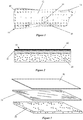
- FIG. 1 An example of an orthopedic product, such as a short arm fracture brace is illustrated in Figure 1 . It is to be expressly understood that other types of products, including other types of braces, splints, casts and other products.
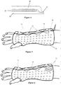
- the descriptive brace 10 of this example includes an inner layer 20, a middle support layer 30 and an outer layer 40 as shown in Figures 2 and 3 .
- the three layers each provide unique functions and when combined into a unitized composite product that creates a unique and superior product.
- the three layers, each described in greater detail below, are molded or laminated together to form a unitized composite material.
- Closures 60 are applied prior to use that enable a health care provider without specialized training to easily form the brace in an appropriate shape and secure the brace to the patient.
- the resulting brace is much more comfortable for the patient and can increase the patient's compliance with its use.
- the resulting brace has many additional benefits over the previous systems as discussed above and below.
- the unitized system of this example enables the brace to be provided in pre-laminated, pre- shaped or in blank sheets and provided in sizes according to a desired use, such as for supporting a wrist, arm, knee, neck or other body location.
- the system is then easily customized to the particular patient as discussed below.
- the system in an example, also allows the brace to be adjusted as necessary by the patient to accommodate swelling or other issues. This adjustability also allows the brace to be customized to the particular body part being supported.
- the brace system is heated with dry heat to become thermoformable for shaping within a few minutes.
- the brace system at temperatures between 70°C (160 degrees Fahrenheit) to 120°C (250 degrees Fahrenheit) (the Target Temperature), is pliable for ease in shaping but still is able to maintain some degree of stiffness so not to be overly fluid, that is beyond the glass transition temperature of the material.
- the system can then be placed on the patient without burning or causing discomfort to the patient during this process.
- the relatively low density foam inner layer insulates the high density hot middle plastic layer from the body.
- the skin having a higher density than the foam, actually cools the foam more rapidly than the foam can transfer heat to the skin thus protecting it from burning at the temperatures used.
- the system is then formed to the exact shape desired for that particular patient easily and without the need of specialized skill using a method described below.
- the system of an example is designed to allow the time during which the brace system is malleable to be controlled. This is referred to herein as the "dwell time" for the brace. This is a critical time in that it is the time that physician or technician has to precisely mold the brace onto the patient's body.
- This example controls the dwell time by the selection of the middle layer material, the density/thickness of the middle layer material, the temperature range at which the middle material is malleable and the insulative qualities of the inner and outer layers.
- dwell time can be adjusted by the user depending on the temperature the item is heated to, higher temperatures resulting in longer dwell times.
- the dwell time is controlled by the initial temperature that the middle layer is heated, by the material choice for the middle layer, by the thickness and density of the middle layer, and by the insulative characteristics of the inner and outer layer.
- This example uses materials for the rigid middle layer that are malleable at temperatures at or around 90°C (200 degrees Fahrenheit) and down to about 70°C (160 degrees Fahrenheit).
- the forming temperature range of these materials by themselves would not normally enable the material to be malleable for a sufficient time and would cause severe discomfort or injury to the patient. These materials by themselves would cool in a matter of seconds when removed from the heat source.
- the encapsulation in the low density insulating foam inner and outer layers is an important innovation that increases the dwell time and allows it to be varied by the above means while at the same time, insulating the patient for the dangerous heat of the inner layer.
- the composite material for the products is radiolucent. This allows X-rays and other imaging procedures to be conducted on the patient without removal of the product. This saves considerable time and expense in order to check the status of the healing process.
- the composite material is able to be formed into complex shapes by heating the material and shaping, sewing and otherwise manipulating the material while it is in a malleable shape, then allowing it to cool and retain its new shape in a rigid form.
- the composite material may also be created in a "blank” form and then formed in situ to create a desired shape and custom fit. This allows flexibility and customization without a large inventory of products.
- the composite of this example includes a soft inner foam layer 20 assembled by laminating or molding or other manufacturing processes to the middle support layer 30.
- the inner foam layer 20 provides comfort next to the skin. It can protect the patient's skin from abrasion and heat from the middle layer 30 as well as being water proof (non absorbent).
- This layer may be formable at the Target Temperatures to provide a precise fit to the smallest details of the patient.
- the particular foam composition for this layer is low density as discussed above to dissipate heat so the patient is not harmed when the warm brace is initially placed around the body part.
- the foam may not be malleable but is able to compress to comfortably fit closely around the body part of the patient.
- the foam provides cushioning as well to increase the comfort and compliance of use.
- the foam in the example is of a closed cell construction though alternatives may be open cell to provide breath-ability if waterproof features are not desired.
- This layer may also be of a foam formulation to accept and dispense therapeutic chemical additives such as antimicrobials, skin lotions or other medicines and chemicals.
- visco-elastic memory foam may be used for this layer to conform precisely to the body.
- the inner layer 20, in this example, may include without limitation, materials such as a closed cell foam layer, an open cell foam layer, a gel or soft polymer layer, an insulating fabric, a multilayer or lofted insulating fabric layer, or any other cushioned insulative layer.
- This layer provides cushioning for comfort to the patient, along with insulative characteristics for maintaining the heat of the middle layer to increase the working time for shaping the material as well as providing a support surface for sewing operations.
- This support surface provides a securing mechanism for the threads of the sewing seam as well as providing a smooth surface for moving the heated composite material through the sewing apparatus without sticking.
- this layer insulates the heated malleable composite material from the base of the sewing apparatus to keep it malleable long enough to conduct complicated sewing steps.
- the base of most sewing apparatus are typically a large thick metal surface that will quickly sink heat away from an uninsulated material in a few seconds.
- the sliding coefficient of friction of this layer is about 1 or less when heated to a temperature of about 90°C (200 degrees Fahrenheit), meaning that it will slide across a metallic surface without undue force or stickiness.
- This inner layer 20 in the example is formed from a foam material, such as from a variety of crosslinked Polyethylene (“PE”) and Ethylene Vinyl Acetate (“EVA”) foams or other suitable materials.
- the material is moldable at the Target Temperatures.
- this layer may also be moldable at higher temperatures about 150°C (300 degrees Fahrenheit) which are achieved in the manufacturing process. This allows the material to be compression molded into various forms during manufacturing and for the edges to be heat sealed closed to the outer layer thus encapsulating the mid layer.
- This layer can be treated with various medicines or antimicrobial treatments.
- An additional layer may also be affixed inside of the inner layer to provide antimicrobial features. Other therapeutic properties may be incorporated as well into these additional layers.
- This layer could be foam, fabric, non- woven fabric or other suitable material
- the middle layer 30 of this example is a thin thermoformable polymer plastic material that becomes pliable at the Target Temperature yet substantially rigid at room temperature.
- This layer provides a substantial amount of support for the body part. It may be engineered to have varying degrees of flexibility and rigidity as desired by varying the polymer material composition. The features may also be varied by the material thickness or by perforations or cut-outs. This layer may be molded with varied thicknesses, tapered edges, ribbing, holes and features that provide the desired rigidity, strength and flexibility required for the intended healing purpose.
- the middle layer 30 of the example is formed from a proprietary thermoplastic polymer material that includes specific characteristics.
- the material is easily formable at temperatures between about 70°C (165 degrees Fahrenheit) and 90°C (200 degrees Fahrenheit), and rigid at temperatures below 50°C (130 degrees Fahrenheit).
- the material preferably has a low glass transition temperature as well which will allow it to become slowly rigid from the malleable state.
- the material thickness ranges preferably within the range of about 0.6mm (0.025 inch) to about 3mm (.125 inch). This material has a hardness greater than Shore 7OA, and preferably within a range from about Shore 65D to about 80D when measured in accordance with ASTM D2240.
- the material has adequate structural strength with high impact strength, low notch propagation and durability.
- the material of the example has a tensile strength in the range of 40 - 60MPa (6000 - 9000 psi) (ASTM D638), and preferably 50MPa (7500 psi), elongation at break of 5% (ASTM D638) and a flexural modulus of between 1.9 - 2.3GPa (270,000 - 340,000 psi) and preferably 2.1GPa (308,000 psi) (ASTM D5023).
- the specific gravity of the preferred material is between about 1 - 1.5 grams per cubic centimeter (ASTM D79).
- the middle layer 30 of another example is preferably formed from Polyvinyl Chloride (“PVC") sheet, Amorphous Polyethylene Terephthalate (“APET”), Recycled Polyethylene Terephalate (“RPET”) or PVC foam such as SintraTM or KomatexTM.
- PVC Polyvinyl Chloride
- APET Amorphous Polyethylene Terephthalate
- RPET Recycled Polyethylene Terephalate
- PVC foam such as SintraTM or KomatexTM.
- Other preferred materials include without limitation polycaprolactone, and caprilactone.
- HDPE Low or High Density Polyethylene
- Additional materials that are thermoformable at temperatures below 120°C (250 degrees Fahrenheit) while rigid at room temperatures may be used as well.
- the outer layer 40 in an embodiment example, is formed from a stretchable material that will easily stretch, maintain memory to return to their original shape and posses high strength and durability characteristics.
- the material includes but is not limited to knit nylon spandex blend, knit polyester spandex blend, fabrics of nylon, polyester or other fibers that stretch due to the design of the knit, and rubberized materials.
- Spandex is the generic term for a highly elastic synthetic fiber.
- the preferred material in one example includes a blend of nylon or polyester with spandex. Also, the preferred material for this example does not become tacky when heated to temperatures above 90°C (200 degrees Fahrenheit) and glides easily across surfaces when heated at that temperature. The sliding coefficient of friction of this layer is about 1 or less when heated to a temperature of about 90°C (200 degrees Fahrenheit), meaning that it will slide across a metallic surface without undue force or stickiness.
- the outer layer in another preferred example, includes the stretchable material described above along with another foam layer that, in an example, has many of the features of the inner layer including providing insulation against the heat of the middle layer when forming the brace about a body part. Additionally it provides aesthetics to the brace and also provides protection from abrasion from the middle layer. It is intended to provide a durable and comfortable covering to the rigid and perhaps rough perforated middle layer.
- the outer layer is formed from a foam, such as urethane foam, foam rubber or EVA foam that is moldable at a temperature above the Target Temperatures. This allows the outer layer to be thermoformed during manufacturing with relief features, ribs, depressions or cosmetic shapes and to have the edges sealed to the inner layer at temperatures considerably higher than the Target Temperatures.
- the outer layer in the example, does not thermoform at the Target Temperature, but will stretch to follow the shape of the mid layer. Since it does not thermoform, it will not pick up the imprint of the elastic wrap or compression tube and will remain smooth and attractive in appearance. It can be thermoformable at the Target Temperature if these features are not desired.
- the outer foam layer may also be of a stiff foam to provide additional support, as well as environmental protection, aesthetics and also to provide some support during the thermoforming process.
- fabric, synthetic leather or other cosmetic covering may be laminated to the outside of this layer for purposes of aesthetics or durability.
- fabric can be applied known as unbroken loop which has a surface compatible with common hook and loop fasteners such as VelcroTM. This allows closures, extra supports, multipart braces and other devices to be instantly connected using common hook strip fasteners.
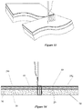
- the composite material may include holes perforated through the three layers to form holes 12 in various amounts and shapes to provide ventilation, forming features, access to wounds or access to catheters etc. These apertures also allow the middle layer to expand and shrink as necessary as the brace is being molded to the body part.
- the unitized brace may also be perforated to create apertures 14 for body parts such as thumbs, toes, etc.. It may also be perforated to accept various closure system attachments. In most cases, the example is wrapped once around the extremity and overlapped to some degree. This is to accommodate the varied body diameters and shapes encountered within each sized product and is a feature not found with typical plaster and fiberglass braces. The overlap is also the spot where the closure devices will be placed that allow the brace to be opened or closed in circumference during use.
- the middle support layer may include perforations as well. This allows the layer to be easily conformable to the three dimensional surfaces of the body is to perforate it with small holes close together resulting in an open structure from 25% to 50% open. This method creates a matrix framework around the holes that, when heated and pliable, can more easily form by deforming around the small holes moving into the small holes or stretching the small holes apart. With this perforation method, thicker stiffer materials can be used than would not normally be adequately formable without the perforations. Perforating also allows the plastic polymer to be formed at lower temperatures than a continuous layer due to deforming process mentioned above which is important for patient comfort and safety. The thick matrix framework when cool and formed in a cylindrical fashion becomes very rigid as needed for the most supportive braces.
- perforations which increases the comfort and compliance of the patient.
- These perforations to the middle layer are separate from the ventilation holes that are used for ventilation and cooling purposes which must be punched through all of the layers and are intended to be larger and further apart.
- the perforations remove between twenty-five to sixty percent of the weight of the middle layer. These perforations are particularly useful when the material for the middle layer includes PVC sheet, APET and RPET.
- foam materials such as PVC foam (including SintraTM and KomatexTM) and APET may be foamed when extruded or molded with 20 to 50 percent air or gas bubbles instead of perforations.
- Other foamed materials may be used such as rigid EVA foams and other high density foamed polymers. Their use depends on the desired rigidity and durability required for each use.
- the middle layer 30 may have a varying topography such as by having increased thicknesses in areas where additional rigidity is desired and decreased thicknesses in areas where more flexibility is needed.
- the entire brace system is formed from a single material and behaves in much the same manner as described for the multi layer brace above. This material would have strata that are more and less dense by incorporating more or less gas bubbles into a foam material. The center portion of the material has a higher density (less or no gas bubbles) than the outer portions of the material (more gas bubbles). This can be accomplished by using a foam extruded material where the foam is crushed or manipulated during the manufacturing process so it becomes more dense.
- the middle layer may also include multiple layers of heat formable material. These different materials may include different characteristics of rigidity and heat formability, or they may only be on certain areas of the middle layer to increase rigidity or flexibility at certain areas of the middle layer. Also, additional materials may be inserted in the middle layer at desired locations to provide additional rigidity or flexibility as needed.
- the manufacturing process of an example uses a heat press process.
- the three component layers are placed in the appropriate mold or die, depending on the particular product being formed.
- the mold/die with the three (or more) layers in place is then placed into a convection oven and heated to 150°C (300 degrees Fahrenheit).
- the heated mold/die is then placed into a press.
- the press is closed so that the three layers are compressed into the mold shape.
- the press remains closed until the three layers have cooled sufficiently to retain their shape.
- the molded composite material product is ejected from the mold.
- Other finishing steps may be taken to complete the product, such as forming holes, attaching closure mechanisms, etc.
- Another manufacturing process also uses a molding process.
- the middle layer 30 is sandwiched between the inner layers 20 and outer layer 30 and recessed from the edges of those layers during the molding process.
- the layers are all heated above the Target Temperature.
- the mold includes a cut-off line on its outer edge to cut the foam of the inner layer 40 and outer layer 20 as well as any fabric layers.
- a bar compresses the layers to a high degree.
- the edges of those layers are pinched to seal the edges of the product and tightly closed permanently bonding all layers in the molding process. This provides a clean, soft, rounded thin edge 42 to the brace as shown in Figure 4 that is durable, comfortable and less prone to abrade the skin which is a common problem with traditional plaster and fiberglass braces.
- edges may be sealed with an edge tape on the exposed edges.
- the edge tape seals the exposed edges and also forms a soft edge.
- This tape can be of a flexible thin fabric or foam with an adhesive backing that is easily applied by hand to edges of the brace where desired.
- Another manufacturing process is compression molding which typically includes the following steps. Fabric layers, if used, are laminated to the inner and/or outer layers. Blanks and features are then die cut out of each layer. The middle layer is put inside the inner and outer layers set back from the edges. The three layers are heated to the critical molding temperature which is above the Target Temperature. The heated layers are placed in a compression mold where the layers are compressed to cut features in the layers and edges are sealed by a compression bar. The layers are cooled by the mold to form the composite material.
- this example does not require lamination as the parts are molded together. However, this example may also include the layers 20, 30 and 40 laminated together. The outer layers extend beyond the middle layer to form a soft edge 42. The edges of the outer layers may be laminated , laminated and molded or molded with heat sealed edges and spot adhesive.
- a closure system 60 is used to secure the product closed about the body part as shown in and to allow some degree of compression to hold the injury in reduction.
- This system may be double sided adhesive tape placed in between the overlap, adhesive tape applied to the seam or circumferentially, or a mechanical closure system.
- These mechanical closures may consist of, but are not limited to, hook and loop fastener, snaps, laces, toothed zip ties, ratchet lace systems, ski boot type buckles and the like.
- the closure system can be fastened and the tension adjusted by the attending doctor or technician as the brace is applied with a tamper proof closure so it cannot be adjusted by the patient.
- the closure could be set so the patient has the means to only loosen or tighten the brace a limited amount but it cannot be prematurely removed. This allows the patient to loosen the brace if there is discomfort or swelling and tighten it if too loose without going back to the physician.
- the system could be set by the attending doctor or technician so the patient has the ability to adjust and completely remove the brace. This can extend the life of the brace so it can be used as a temporary brace to protect the partially healed injury during rigorous use. Using this controllable and adjustable system, the attending doctor or technician has options appropriate for all phases of healing and can enable or lock out the patients ability to make adjustments.
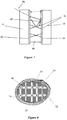
- One attachment mechanism in particular includes a tensioning cable system 70 as shown in Figure 5 .
- the system 70 utilizes a series of guide members 72 on opposite sides of the brace system 10. Lace 74 is laced through guide members 62 on alternate sides as shown in Figure 5 and then through locking member 76. The lace is drawn tight so the brace has the appropriate tension on the body part and locked into place.
- An alternative lacing system shown in Figure 6 is similar to the above mechanism but utilizes a reel mechanism 78 to mechanically tighten and lock the tightened lace that can be easily released and tightened with micro adjustments.
- the fastening mechanism 60 include cable reel elements such as the cable reel attachment systems distributed by BOA Technology Inc. and described in U.S. Patent Nos.
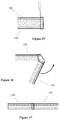
- the lacing system shown in Figure 7 provides an edging 80 along the edges of the cast, brace, or any other product.
- the edging 80 includes a series of perforations 82 spaced vertically along the edging 80.
- the edging may be secured with hook and loop fasteners, sewn onto the product, adhesively mounted, or otherwise attached to the product.
- the bottom of the edging includes a hook and loop strap extending around the circumference of the product.
- Alternative mechanisms may be used as well such as strap and buckle or any other known attachment mechanism.
- a monofilament line 86 is inserted through opposing sections of the perforations 82, by use of a needle or awl 88.
- the ends of the line 86 end at the end of the product adjacent the hook and loop strap. The ends are pulled to tighten the line so that the edges of the product are pulled together. Once the product is tight about the body part or other object, the line 86 is wrapped around the product and secured by the hook and loop strap.
- Cord locks or other mechanisms may also be used to secure the line as well. Cables, laces or other mechanisms may be used in lieu of the monofilament line.
- the securing mechanism 50 of the brace system 10 of an example allow the edges of the brace system to overlap. This overlap amounts to about twenty-five percent (25%) of the circumference or less.
- the closure system discussed above is mounted on this overlap. This increases the adjustability of the brace system to increase or decrease the compressibility on the injured body part.
- the unitized brace system 10 may be provided in various sizes to fit different body parts and sizes of body parts.
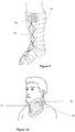
- the adjustable overlap, as shown in Figure 8 of the unitized brace system of this example provides further capability to custom fit the brace to a particular body part of a particular patient by allowing edge 22 of the brace to overlap the opposing edge 24.
- the securing mechanism 50 allows the brace to be adjusted by increasing or decreasing the amount of the overlap to more closely fit the patient's body part.
- the above unique combination of brace features provides a lightweight yet structurally rigid brace that is easily custom formed to the patient on site without the need for specialized training or skills.
- the resulting brace is patient compliant and can be adjusted as needed to increase compliance with its use.
- the adjustability can also decrease soft tissue injuries.
- the brace can be formed with dry heat so many heat sources can be used.
- the patient is protected from damage or discomfort from the heated brace during the forming process.
- the brace is waterproof and durable and can be reused and reshaped as needed.
- the materials used being mostly polymers, provide a high degree of radiolucency.
- the body part can be examined through x-rays without the need to remove the brace as compared with Fiberglass and plaster which are not typically radiolucent. There is a reasonable potential for using recycled polymers in the construction of the middle layer that may impact the beverage container industry.
- the unitized brace system of this example may be provided in a relatively flat shape or generally in the shape for a specific body part, such as a wrist, ankle, knee or other body part as well as in general sizes, such as large, medium, small.
- the braces may also be pre-formed in some cases to approximately fit the body part for trial of size or in the case where a more complex structure requires it.
- the system can then be heated and custom shaped to specifically fit the body part that it is to support.
- the adjustable overlap also contributes to this custom fitting as discussed above.
- the unitized brace system will then fit the body part in a comfortable yet rigid manner.
- FIGS 1 , 5 , 6 and 9 - 11 Further examples used in types of braces are shown in Figures 1 , 5 , 6 and 9 - 11 .
- This use is of particular advantage since this area of the body is particularly sensitive and the contour shape varies greatly from person to person.
- This use has advantages brought by the durable nature of the materials used since they are less prone to fatigue and cracking under body weight.
- the ability to adjust tension in this area prone to swelling is of great advantage.
- the unitized brace system 10 can be thermoformed utilizing a dry heat source in lieu of typical water activated materials presently in use.
- a dry heat source in lieu of typical water activated materials presently in use.
- One disadvantage of these typical materials is that the body part, and often wounds associated with the injury are wetted during the brace process. They typically remain wet many hours after brace causing the skin to become uncomfortable, abraded and more prone to build up of microorganisms at precisely the time when sterility is most desired. Examples stay dry during the brace process and provide only a brief and comfortable dry heating of the body part. Healing begins in a dry environment less prone to the buildup of microorganisms and infection. The use of antimicrobial treatments incorporated inside the brace can be more effective in this dry environment
- the brace system can also be shaped and secured to the body part without the need for extensive training since it is pre-made and not built on the patient. These pre-made braces have most of the labor done at the factory where they are manufactured saving valuable high cost hospital and clinic time adding considerable advantage.
- the brace system is also waterproof, lightweight and comfortable thus enhancing the patient's compliance in the use of the system.
- the polymer plastics used are much more durable than fiberglass or plaster and resist fatigue and cracking. This combined with ability to adjust the tension and size of the brace or remold it can allow a single brace to be used throughout the healing process where typical braces are replaced 1-3 times upon repeated visits to the hospital or clinic.
- brace when warm, soft and pliable must be formed to the intimate shapes of the body to best stabilize the injury under reduction.
- a loose fitting brace with voids between the body and brace can allow undesired movement.
- a perfectly formed brace that meets every detail of the body can provide stabilization without being excessively tight and in many cases, just meeting the body with out compressive force. This is the most comfortable configuration that will provide the needed support yet not constrict, reduce circulation or irritate. In order to achieve this desired effect, a unique method of forming this brace to the body must be incorporated.
- this brace is best formed when warm and pliable by applying compressive circumferential force in excess of the comfortable level for long term wear. Once the brace is cool and rigid in a few moments, this compression can be removed and the closures can be adjusted to provide the desired amount of closure of the brace for comfort and stabilization.
- a cast of the example is similar to the brace as described above.
- the primary difference, if any, is that the middle support layer is formed of a more rigid material. This can be accomplished by simply providing a material with greater thickness, or by selecting a material that has a higher durometer and tensile strength.
- the cast is applied by first heating the cast to the Target Temperature, applying it around the body part, and compressing the malleable material into the appropriate shape around the body.
- the lacing system can then be pulled tight to apply the appropriate amount of tension and to secure the cast.
- the tension on the cast can be adjusted to accommodate increase or decrease in swelling, itching or other issues.
- the cast of the composite material is waterproof so that the patient can bathe or shower with it on without the use of protection around the cast, and the patient may even swim with it.
- the cast is easily removable by loosening the tension in the lacing system so that a cast saw is not necessary.
- the system in an example, provides a unitized splinting system that is far superior to previous systems.
- the system of an example, as used as a splint is shown in Figures 12 - 17 .
- This splint system is illustrated as a wrist splint but it is to be expressly understood that it can be used for any type of splinting situation, such as but not limited to foot splints, neck splints, leg splints, arm splints etc.
- This splint system 90 of this example includes an inner comfort padding layer 20, a middle support layer 30 and an outer durable padding layer 40 as shown in Figure 2 .
- the three layers each provide unique functions and when combined into a unitized splint create a unique and superior splint.
- the three layers each described in greater detail below, are molded or laminated together to form a unitized splint.
- the resulting splint is much more comfortable for the patient and can increase the patient's compliance with its use.
- the resulting splint has many additional benefits over the previous systems as discussed above and below. It is to be expressly understood that additional layers beyond the three layers described herein may be used as well.
- the splint system of this example enables the splint to be pre- laminated, pre- shaped or in blank sheets and provided in sizes according to a desired use, such as for supporting a wrist, arm, knee, neck or other body location.
- the system is then easily customized to the particular patient as discussed below.
- the system in a example, also allows the splint to adjusted as necessary by the patient to accommodate swelling or other issues. This adjustability also allows the splint to be customized to the particular body part being supported.
- the splinting system is heated, preferably with dry heat (although hot water may be used as well), to become thermoformable for shaping within a few minutes.
- the splinting system of this example at temperatures between 70°C (160 degrees Fahrenheit) to 120°C (250 degrees Fahrenheit) (the Target Temperature) is pliable for ease in shaping but still is able to maintain some degree of stiffness so not to be overly fluid, as would be reached beyond the glass transition temperature of the material. Other Target Temperature ranges may be used as well with other materials.
- the system can then be placed on the patient without burning or causing discomfort to the patient during this process.
- the relatively low density foam inner layer insulates the high density hot middle plastic layer from the body.
- the skin having a higher density than the foam, actually cools the foam more rapidly than the foam can transfer heat to the skin thus protecting it from burning at the temperatures used.
- This system which is preferably dry heated is then formed to the exact shape desired for that particular patient easily and without the need of specialized skill using a method described below.
- FIG. 12 Examples of different types of splints are shown in Figures 12 - 17 .
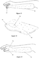
- the splint 90 in Figure 12 has a flat custom shape for use in splinting an arm or wrist with an "L" shaped upper portion 92. Once the splint has been heated and molded (as described in greater detail below) the L shaped upper portion 92 is molded to comfortably support the wrist and thumb of the patient as shown in Figure 13 .
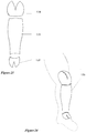
- FIG. 14 Another example of a splint for supporting a wrist or arm injury is shown in Figures 14, 15 .
- the blank splint 94 includes a larger upper portion 96 with an aperture 98 formed in it. This splint is heated and molded to custom fit the patient with their thumb extending through the aperture 98.
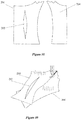
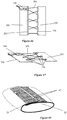
- FIG. 16 Another example of a splint is illustrated in Figure 16 .
- This splint 100 is intended for use in splinting a leg injury.
- the splint includes slits 102 formed in each side of the lower portion of the splint which acts a hinge during the molding process so the lower portion of the splint can be pivoted to create a foot or boot portion on the splint.
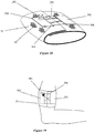
- FIG. 17 Another splint is shown in Figure 17 .
- This splint 104 has unbroken loop fabric laminated onto the outer surface 40. This enables two more sections of splints to be attached in a desired configuration to one another by sections of unbroken loop fabric 106. Thus, complex shapes can be created as needed in a quick and easy method.
- the splint when warm, soft and pliable must be formed to the intimate shapes of the body to best stabilize the injury under reduction.
- a loose fitting splint with voids between the body and splint can allow undesired movement.
- a perfectly formed splint that meets every detail of the body can provide stabilization without being excessively tight and in many cases, just meeting the body with out compressive force. This is the most comfortable configuration that will provide the needed support yet not constrict, reduce circulation or irritate.
- a unique method of forming this splint to the body must be incorporated.
- the splint is best formed when warm and pliable by applying compressive circumferential force in excess of the comfortable level for long term wear. The compressive force will cause the splint 10 to conform and shape. Once the splint is cool and rigid in a few moments, this compression can be lessened to provide the desired amount of tension of the splint for comfort and stabilization.
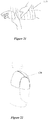
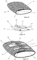
- the preferred method of compression uses an elastic band 112 as shown in Figures 18 - 20 that can be quickly wrapped around the warm pliable splint as soon as it is installed.
- This elastic band may be fabric or rubberized material in the appropriate width, thickness and elasticity for the particular splint type in a length to adequately wrap over the entire splint.
- Compressive pressure can be varied simply by pulling on the band as it is wrapped. This process will insure that every part of the splint is formed to the body and voids are not created. It should be expressly understood that, though this process is commonly used to apply compressive pressure to wounds, it is a unique process to apply it to temporarily form a splint that is in a warm and pliable state for the duration of cooling, then to be removed.
- a strip of hook fastener 110 is secured to the lower end of the splint 108 or the entire surface 40 can include unbroken loop fabric.
- the elastic band 112 can then be fastened to the element 110 to secure the band initially.
- the elastic band will naturally engage with the hook fastening elements. This allows many options for fastening the splint to the body or attaching multiple splint pieces together. This allows complex configurations to be formed.
- the elastic band 112 is then wrapped snugly about the splint as shown in Figures 19, 20 so that the warm middle layer 20 conforms about the body, as shown in Figures 20 , 21 .
- the elastic band is then removed as the splint cools to form a rigid support structure.
- the above unique combination of splint features provides a lightweight yet structurally rigid splint that is easily custom formed to the patient on site without the need for specialized training or skills.
- the splint can be formed with dry heat so many heat sources can be used.
- the patient is protected from damage or discomfort from the heated splint during the forming process.
- the splint is waterproof and durable and can be reused, reshaped and washed as needed.
- the materials used, being mostly polymers, provide a high degree of radiolucency.
- the body part can be examined through x-rays without the need to remove the brace as compared with fiberglass and plaster which are not typically radiolucent. There is a reasonable potential for using recycled polymers for some or all of the components which has an environmental advantage.
- the unitized splinting system of this example may be provided in a relatively flat shape or generally in the shape for a specific body part, such as a wrist, ankle, knee or other body part as well as in general sizes, such as large, medium, small.
- the splints may also be pre-formed in some cases to approximately fit the body part for trial of size or in the case where a more complex structure requires it.
- the system can then be heated and custom shaped to specifically fit the body part that it is to support.
- the unitized splinting system 10 can be thermoformed utilizing a dry heat source in lieu of typical water activated materials presently in use.
- a dry heat source in lieu of typical water activated materials presently in use.
- One disadvantage of these typical materials is that the body part, and often wounds associated with the injury are wetted during the splinting process. They typically remain wet many hours after splinting causing the skin to become uncomfortable, abraded and more prone to build up of microorganisms at precisely the time when sterility is most desired. Examples stay dry during the splinting process and provide only a brief and comfortable dry heating of the body part. Healing begins in a dry environment less prone to the buildup of microorganisms and infection. The use of antimicrobial treatments incorporated inside the splint can be more effective in this dry environment
- the splinting system can also be shaped and secured to the body part without the need for extensive training since it is pre-made and not built on the patient. These pre-made splints have most of the labor done at the factory where they are manufactured saving valuable high cost hospital and clinic time adding considerable advantage.
- the splinting system is also waterproof, lightweight and comfortable thus enhancing the patient's compliance in the use of the system.
- the polymer plastics used are much more durable than fiberglass or plaster and resist fatigue and cracking.
- the unitized splinting system 10 is provided as a kit to the individual, the orthopedic specialist, physician, technician, first responder or other entity.
- the appropriate kit type and size for the body part to be supported is selected.
- a dry heat source as discussed below is applied to the splint 10 until the splint is sufficiently pliable to allow it to be shaped. This should be in the range 70°C to 150°C (160 F to 300 F) (Target Temperatures) and preferably 90°C (200 F). In the example, the temperature of the splint is maintained at the desired temperature, such as 90°C (200 F) for about five to ten minutes.
- the dry heat source can be an oven, microwave, or as discussed below, a heat bag, an internal heating mechanism or an exothermic heat source
- the splint Once the splint is sufficiently heated and pliable, approximately 5-10 minutes, it is removed from the heat source and the elastic bandage is affixed to the splint.
- the splint is then applied directly to the body part as shown in Figures 18 - 21 .
- the lower density polymer foam that makes up the inner layer 40 dissipates the heat so that that the individual does not suffer any pain or discomfort from the heat.
- the splint will be pliable, in the example, for about three to ten minutes. This allows ample time to form the splint about the body part.
- An elastic wrap 112 is utilized to provide compression to mold entire splint specifically to the body part as shown in Figures 18 - 21 .
- the elastic wrap 90 applies pressure uniformly over the splint 10.
- the elastic wrap 90 can be an elastic band, or an elastic compression bandage formed from nylon/tricot knit, rubber, urethane, spandex or any other suitable material.
- the injury may be reduced or aligned during the forming process as well.
- the dwell time of the splint should be sufficient to allow the forming and reduction to occur.
- the combination of the pliable heated thermoformable layers along with the uniform pressure forms the splint to the body part.
- the mid layer provides the majority of the shape and support.
- the inner layer if formed of a thermoformable material will also shape to conform about the body part as well.
- the outer layer in the example, does not thermoform, but will stretch to follow the shape of the mid layer. Since it does not thermoform, it will not pick up the imprint of the elastic wrap and will remain smooth and attractive in appearance. This layer can be thermoformable at the Target Temperature if these features are not desired.
- the composite material also has particularly utility for veterinary use, particularly with equines. It is difficult to provide immobilizing supports to large animals such as horses as well as other domestic and wildlife animals.
- the composite material as described above is lightweight and high strength and with the ability to be custom fitted to limbs, a cast/splint/brace can be easily custom fitted without undue disturbance to the animal. It can also be shaped into complex shapes (as described in greater detail below) in situ so the animal does not need to be transported. It can also be scaled up or down in size as necessary to be used with smaller animals.
- the system in an example, provides a custom formable protective gear system that is far superior to previous systems.
- the protective gear can be for uses such as athletic gear such as shin guards, wrist guards, etc.; military and law enforcement protective gear, for workplace protection and for any other use where custom formed protection is desired.
- the shoulder protector 120 includes multiple parts that are cut, heated and then sewn together (in a process described in greater detail below). The assembled parts are then heated and custom fitted to the body of a user to provide protection to the shoulder area.
- FIG. 23 Another example of a use of the composite material is a shin guard used in many sport activities and law enforcement and military applications to protect a person's shins and knee from damage.
- multiple parts 128, 130, 132 are formed from the composite material, then heated, and sewn to produce thin profile closely fitted product that can be later heated and fitted precisely to the body.
- a knee cap and foot protector is incorporated using multiple parts darts and hot sewn seams.
- Figures 25 - 27 show a protective glove used in athletics, law enforcement or the military that has a complex multi part interior construction that is made from the example composite material sewn together while hot. This demonstrates how tiny curved edge parts can be sewn together when hot and pliable using standard sewing machine methods. This would not be possible with rigid plastics alone.
- the finished glove can be heated to 90°C (200 degrees Fahrenheit) and put on the hand. Then, the wearer can flex the hand and fingers to the desired position most commonly used, such as holding a hockey stick, shield or baton and hold that shape until the item cools providing a custom fitted strong supportive three dimensional fitted product, Once again, this process would be most difficult to achieve using standard materials and methods.
- Other types of protective gear may be created as well for equestrian uses, industrial and construction gear, geriatric protective products and many other uses.
- the protective gear system of this example enables the protective gear to be pre-laminated, preshaped or in blank sheets and provided in sizes according to a desired use, such as for protecting a wrist, arm, knee, neck or other body location.
- the system is then easily customized to the particular user as discussed below.
- the system in an example, also allows the protective gear to adjusted as necessary by the user. This adjustability also allows the protective gear to be customized to the particular body part being supported.
- the protective gear system is heated, preferably with dry heat (although hot water may be used as well), to become thermoformable for shaping within a few minutes.
- the protective gear system of this example at temperatures between 70°C (160 degrees Fahrenheit) to 120°C (250 degrees Fahrenheit) (the Target Temperature) is pliable for ease in shaping but still is able to maintain some degree of stiffness so not to be overly fluid, as would be reached beyond the glass transition temperature of the material. Other Target Temperature ranges may be used as well with other materials.
- the system can then be placed on the patient without burning or causing discomfort to the user during this process.
- the relatively low density foam inner layer insulates the high density hot middle plastic layer from the body.
- the skin having a higher density than the foam, actually cools the foam more rapidly than the foam can transfer heat to the skin thus protecting it from burning at the temperatures used.
- This system which is preferably dry heated is then formed to the exact shape desired for that particular user easily and without the need of specialized skill using a method described below.
- a heat source for heating the splints to the Target Temperature as described above in order to shape the system to the body part.
- One example of the heat source includes a heating pouch 150 as shown in Figures 28 , 29 , that is easily stored and transported.
- the heating pouch includes an outer insulation layer 152, opposing heating elements 1274 in a sheet fashion and a liner bag 156, preferably durable on the outside and non-stick on the inside, that holds the heating element and insulation.
- the heater elements can be made of electrical heat wire or heating foil or other electrically activated design.
- the heater bag 150 is easily opened to accept the splint and closes during the heating process.
- a closure system such as hook and loop, zipper of buckles closes the bag to hold in heat.
- the heater element is connected to an electrical power source, either 110-240 VAC standard plug for connection to an electrical outlet, or a 12 V transformer or a 12V DC battery or vehicle electrical power source and maintains the Target Temperature accurately via a thermostat or heat control device.
- the heating pouch may also include an optional temperature probe that monitors the temperature applied to the bracing system.
- the unitized splinting system 10 is placed in the case between the opposing electric heater elements.
- the case is activated causing the heater elements to heat the splint 10. Once the splint is heated sufficiently to the Target Temperature and adequately pliable, it is removed for application and forming around the body part.
- This heat source case is easily transported and able to be used in hospitals, clinics, training rooms or even on site for treating an injury. Special ovens or chemical reactions are not needed.
- Another heat source of an example uses an internal heating mechanism built into the unitized splint.
- This may be an electric grid on one or both sides of the middle layer.
- This grid is connected to a power supply which supplies electric current to heat the middle layer to the target temperature. Once forming of the splint is complete, the electric current is turned off and the splint quickly cools. This eliminates the need for an external heating device since it is built into the splint.
- Another heat source of an example utilizes an exothermic heat source 160 shown in Figure 30 .
- a number of chemical reactions exist that produce heat such as carbon/air, Lye/water, air batteries and others. When two or more elements are exposed to each other, the resulting chemical reaction causes heat to be released.
- Typical common uses are carbon/air packets used as pocket heaters for cold weather and Lye/water containers used to heat army "meals ready to eat".
- Similar systems can be used to heat the splints of the example to the Target Temperature by incorporating the heating chemicals into a plastic pouch or bag with adequate room to insert the splint.
- the chemical reaction is made and the splint heated, removed and applied.
- the advantage of such a system is that injury often occurs in the field where medics or doctors do not have access to electricity. This method provides a quick simple method to heat the splint in a self contained fashion and apply it in the methods described above.
- heating means include convection ovens, toaster ovens, radiant lamp heat sources, Infrared heaters and microwave ovens.
- a convection forced air oven may be used.
- Wet heat, such as used with previous thermoformable splints may be used as well. This type of heating requires the immersion of the splint into a container of hot water until it reaches the Target Temperature.
- heating system 10 includes a first enclosure 172.
- the enclosure 172 has an opening 174 along with a sealing mechanism 176, such as sliders used with Zip-Loc bags that forms a waterproof seal on the enclosure.
- the enclosure can be sealed at the manufacturing with the other components sealed inside.
- the enclosure 172 in this example is a bag, such as a plastic bag, made of thin polypropylene or other similar materials.
- the enclosure 172 is of such a size that it can hold the object that is to be heated and formed.
- a second enclosure 180 is inserted inside the first enclosure 172.
- the second enclosure also has an opening 184 with a sealing mechanism 186.
- the second enclosure may be similar to the first enclosure, such as a plastic bag formed from polypropylene or other materials. Both enclosures should be waterproof and able to withstand temperatures above 220 degrees Fahrenheit.
- the heating system 10 also enclosures absorbent materials 188 such as sponges, paper or nonwoven layers that are inserted within the first enclosure 20 and outside the second enclosure 180. These sheets 188 are moistened with water prior to use. The sheets may be pre-moistened or removed from the enclosure 172, moistened by the user and reinserted in the first enclosure. Alternatively, water can be provided without the absorbent materials.
- absorbent materials 188 such as sponges, paper or nonwoven layers that are inserted within the first enclosure 20 and outside the second enclosure 180.
- These sheets 188 are moistened with water prior to use.
- the sheets may be pre-moistened or removed from the enclosure 172, moistened by the user and reinserted in the first enclosure. Alternatively, water can be provided without the absorbent materials.
- the first enclosure 172, the absorbent materials 188 and the second enclosure 180 are bonded together to form a single integral unit.
- the absorbent materials are bonded between the two enclosures.
- the heating system 170 may be provided as a heating system for a user supplied object, or provided as packaging around the object supplied by the manufacturer. In either event, the object 10 that is to be heated and formed is inserted within the second enclosure 180 and sealed therein by sealing mechanism 186. The sheets 188 are moistened either beforehand or at this time and inserted in the first enclosure 172 outside the sealed second enclosure 180. The first enclosure 172 is sealed by sealing mechanism 176.
- the assembled enclosures are then placed in the heat source, such as a common microwave oven.
- a larger microwave oven may be necessary if the object to be formed is of a larger size than can be accommodated in a common microwave oven.
- the microwave oven is then turned on a high operating range. The length of the heating operation depends on the capacity of the oven, the size of the object and enclosures and other factors, but the oven is operated until the water in the absorbent sheets 10 turn to steam.
- the steam ensures that the temperature within the enclosures are at about 100°C (212 degrees Fahrenheit).
- the relatively short amount of time along with the relatively flexible enclosures will minimize the superheating of the steam so that the temperatures should not rise substantially above 100°C (212 degrees Fahrenheit).
- the object within the second enclosure will also be about 100°C (212 degrees Fahrenheit).
- the object is held dry by the second enclosure 180 during this process.
- the heating system 170 is removed from the oven or heat source after the object has been held at the temperature range for a sufficient period of time to ensure that is thoroughly heated at that temperature.
- the manufacturer can provide instructions as to the time and temperature range for heating the enclosures if the object is provided in the enclosures from the manufacturer. Otherwise, the user can experiment to find the optimum time and temperature range.
- the first enclosure is unsealed to allow the second enclosure to be removed. Then the second enclosure can be unsealed to allow the object to be removed. The object can then be formed into an appropriate shape or custom fit to an object.
- heat sources may be used as well as microwave ovens.
- the heating system may be inserted in a container of boiling water to create a similar process.
- Other heating sources may be used as well, such as exothermic heating sources.
- the heating system may also include other examples as well.
- a single enclosure may be used instead of the dual enclosure system.
- the object is inserted into the single enclosure along with moistened absorbent layers, and heated as described above.
- the steam from the heated absorbent layers within the enclosure will heat the object to about 212 degrees Fahrenheit.
- the object may become moistened in this example.
- the composite material as described above has particular utility for creating complex shaped products.
- complex products are formed of separate components that are attached together. Otherwise the product requires complex molding or manufacturing which is not always feasible.
- the processes for attaching separate components is preferably by sewing when possible. Sewing is often used to form single flat sheets into three dimensional complex shapes. Slits can be formed in the flat sheets which are then gathered and sewn together to form shapes as well as hinges in the products.
- the composite material 10 can be cut, shaped, sewn and otherwise manipulated into complex three dimensional shapes.
- the composite material is heated until the middle layer 30 becomes malleable.
- the outer layers (fabric, cushioned insulative or combinations of the two materials or similar materials) are malleable at ambient, elevated temperatures and maintain the stability of the middle layer 30 as it is malleable, and prevent it from unduly stretching.
- the outer layers also provide strength to the middle layer to prevent it from tearing as it is shaped, sewn or cut.
- the stretchable outer layers provide structure for the malleable layer to prevent it from being unintentionally deformed when heated.
- the outer layers have a low coefficient of friction when heated to temperatures up to 105°C (220 degrees Fahrenheit). For purposes of this application, the characteristic of having a low coefficient of friction is referred to as being non-sticky or non-tacky.
- the example composite material described above uses a middle heat formable material with foam insulative layers and outer stretchable fabric layers
- other examples may use differing combinations of materials.
- the composite material may omit the foam insulative layers and use a stretchable material directly attached to the middle layer.
- the stretchable fabric may be omitted from the composite material example.
- the outer layers have a low friction coefficient, unlike melted polymer plastic, so that the composite material will glide through sewing machine surfaces which would otherwise stick to the melted tacky surface of the polymer. Stitching polymer plastic layers together can perforate the material causing weakness and tearing under tension.
- the stretch fabric material 40 of the example as shown in Figure 2 includes tiny strong fibers that not only provide strength when affixed to the composite material as the composite material is heated and shaped, it also provides a smooth low friction sewing surface.
- the sewing needle can penetrate between the tiny strong fibers leaving them undamaged, thus providing a secure seam even while the middle layer is heated and perforated in a weakened and malleable state.
- Those tiny strong fibers will also prevent the holes in the middle layer from tearing after it is cooled and rigid because they will be bonded and unitized as one.
- the malleable middle layer will actually bond to the threads once the material cools to its rigid state.
- the composite material Once the composite material has been heated to a temperature where it is malleable, it can be easily shaped and sewn.
- the composite material can be cut at ambient temperature and at elevated temperatures more easily. Those pattern shapes can then be sewn together into complex three-dimensional shapes.
- the joined components can be reheated to further shape by stretching as they are applied to the body. The seams can be pressed flat as well.
- FIGs 34 An example of the sewing process for the composite material in accordance with the present invention is illustrated in Figures 34 .
- the two components 190, 192 of the composite material 10 are shown in cutaway view in Figure 34 adjacent to one another.
- the two components are heated to a temperature at which the middle polymer layers are relatively soft and malleable.
- the fabric layer 40 and the insulative layer 20 allows the heated material to glide through the sewing surface without sticking.
- the sewing machine stitches a seam through the two components, preferably with a zig zag stitch as shown in Figures 34 and 35 .
- This seam may also be made by overlapping the components 190 and 192 and sewing with single or multiple straight common stitches or other more complex stitches as commonly found on sewn products.
- Figure 35 shows another useful seam technique.
- Two layers of the composite material 190 and 192 can be placed face to face and sewn using a zig zag stitch that passes through the layers on one side of the zig and then into air on the other zag side.
- the joined components can be heated once again to open the seam as shown in Figure 36 , partially opened, and fully opened as shown in Figure 37 .
- This process is particularly useful when joining complex shapes together with multiple seams such as shown in, but not limited to, Figure 42 , a wrist thumb brace.
- the sewing step 210 joins the two layers with a seam in the manner shown in Figures 35 - 37 . They are sewn face to face and then opened when heated to form a flat seam as in Figure 37 . This seam would be extremely difficult to complete, otherwise, considering the small area of the thumb hole and the limited area provided for a sewing machine to operate.
- the composite material is heated to a temperature where the middle layer is malleable, it can be handled similar to a stretch fabric to form desired shapes and fitted body coverings. Then, once it is cooled to room temperature, the resulting shape is an extremely rigid structure due to the rigidity of the middle layer and the three dimensional form whose bent surfaces provide structural strength. This provides a unique composite material that has wide-ranging applications.
- the final shaped product can be repeatedly reheated to allow it to be manipulated, joined, sewn and formed into complex shapes and to conform to complex surfaces such as the body.
- Hot plastic materials alone tend to stretch out and not return to their original shape. When heated, they would burn the skin as they are sewn and applied to the body or handled. They can become extremely tacky and difficult to manipulate.
- the unique composite material 10 when heated, can be stretched, compressed and bent into very complex shapes.
- the stretch fabric layers 40 cause the heated composite material to stabilize about a complex shape as well as to pull tight about the shape to create a close form fit.
- the middle layer can also be formed from a polymer mix that varies so that differing stiffness can be achieved. Also the thicknesses of the middle layer can be varied to provide differing stiffness.
- a spica brace is often used to treat thumb and wrist injuries.
- a thumb wrist spica brace is a type of orthopedic support device used to immobilize the thumb and wrist while allowing other digits freedom to move. It is used to provide support for thumb injuries (ligament instability, sprain, muscle strain, and broken or cracked small bones), gamekeeper's thumb, skiers thumb, osteoarthritis, de Quervain's syndrome , thumb sprains, post-operative use, and post-removal of casting of the hand/thumb.
- a spica brace is difficult to properly fit to the patient and is typically custom made in suta by assembling various materials. Some pre-made products for this use are also used but less common.
- a spica brace is a complex shape, since it must support and maintain the thumb, wrist and arm in proper relation to one another, be adjustable in circumference and fit very closely to prevent movement.
- suta made braces of this nature require complex assembly of parts on the body and are typically made of fiberglass casting material or poly caprolactone sheet that are hand cut, formed and assembled on the body. Elastic banding and hook and loop closures are the norm which are adhered or riveted in place.
- braces of this nature would never be sewn and require great knowledge, practice and time (about 30 minutes) to construct.
- Pre-made braces of this type are typically sewn of a number of different soft fabrics, elastic fabrics, non stretch fabrics or strapping and sometimes include soft foam/fabric laminates. Then, stiffening ribs or pre-formed or malleable rigid supports are inserted into the sewn item.
- the sewing is always done on soft materials, not rigid supportive material because it is too difficult to sew rigid material into three dimensional shapes required to fit the body.
- a soft fabric will be sewn to rigid material, however this varies greatly from sewing complex pieces of rigid materials to each other into three dimensional shapes. In both cases above, the result is a complicated combination of soft and rigid, stretch and non stretch, and strapping materials joined by cumbersome means and multiple parts that provide a product that is less than desirable to wear.
- the process according to claim 1 enables a spica brace to be made of a single composite material sewn together with clean smooth seams that form the base shape.
- Simple or complex closure mechanisms such as hook and loop, lacing systems or other means can be sewn directly to the warm pliable and durable composite material.
- the finished product can then be heated and instantly formed and custom fitted directly on the patient due to its stretch and pliability.
- the result provides a much more wearable item that is thin, supportive, perfectly fitted, waterproof and non absorbent, radiolucent, lightweight and covered with a soft and colorful fabric, When compared with in suta product, far less labor, knowledge and time is required by the practitioner.
- the result is more custom fitted, less bulky and complicated and more comfortable to wear.
- the five or so minutes required to heat and apply the composite material product of an example varies little from the application of other pre-made products.
- the construction of a thumb wrist brace 200 is cut from two blank sheet of the composite material 10 with contours and aperture 202.
- the flat sheet composite material parts can be die cut, cut with scissors, computer operated blade, laser, water jet or other production means.
- the parts are heated to a temperature at which the middle layer is malleable.
- the composite material may be heated at a temperature of 80 to 90°C (180 to 200 degrees Fahrenheit) for 30 seconds to three minutes using a heat press, oven, heat lamps or other heating means.
- the material is malleable at this temperature for a sufficient time to allow the parts to be sewn together by means of standard sewing machines. Zig Zag seams may be used to join pieces butted edge to edge.
- Zig Zag stitching may also be used to sew parts face to face along the edge which is then folded open when still warm to form a flat seam. This method is particularly useful when sewing small sharply curved edges together such as shown in the Figure 42 of the thumb wrist spica which would otherwise not be possible to sew with rigid sheet.. If necessary, the material can be reheated to allow further sewing, attachment and forming processes to occur. It is key to note that the processes described in this paragraph would not be possible to perform with a heated polymer plastic sheet alone as it would not pass through the sewing machine presser foot and feed apparatus because the surface would be sticky causing friction and gumming of the sewing machine and the stitching would perforate and weaken the polymer.
- the laminated outer layers of fabric and foam stabilize the inner layer, reduce friction and provide durability for sewing.
- the completed brace shown in Figure 42 , can be custom fitted to the patient by heating the completed brace, forming about the patient and allowing it to cool into a custom fitted rigid shape supporting the patients joint.
- the brace can be reheated as necessary to achieve a comfortable fit on the patient.
- Figure 22 shows another product made using the example.
- This protective shoulder pad uses three parts cut from flat composite material that are heated to pliability and sewn together with a zig zag stitch with the parts butted edge to edge. The result is a product that is generally shaped as the shoulder but when reheated to 90°C (200 degrees Fahrenheit) and applied to the shoulder it stretches to fit the body perfectly without pressure points or loose areas. Sewing this item of rigid sheet as is the know art would be difficult is not impossible. In addition, forming it to the body without the insulating foam layer would be problematic due to discomfort. Having the outer stretch fabric layer and heat formable inner layer laminated to the mid polymer layer allows easy forming without a lot of pressure applied. A simple elastic wrap applied when warm would shape the part accurately to the body.
- FIG. 23 Another example of the use of the composite material of an example is a shin guard used in many sport activities and law enforcement and military applications to protect a person's shins and knee from damage.
- a shin guard used in many sport activities and law enforcement and military applications to protect a person's shins and knee from damage.
- multiple parts the composite material are cut, heated, and sewn to produce thin profile closely fitted product that can be later heated and fitted precisely to the body.
- a knee cap and foot protector is incorporated using multiple parts darts and hot sewn seams.
- the closure system 250 of this example is able to be attached at desired points on many different products.
- the product used in this example is a brace 10 (although any other orthopedic product such as a cast could be used as well as non-orthopedic products) that has side edges 22, 24, such as the cast disclosed in copending application 12/013,449.
- the outer layer of the brace of this example includes a layer 260 of unbroken loop fabric, such as Velcro8, distributed by Velcro USA, Inc as shown in Figure 43 .
- the outer layer may be entirely formed of unbroken loop fabric 260 shown in an examplein Figure 43 .
- the unbroken loop fabric layer 260 can be adhesively bonded, molded, sewn or otherwise attached onto the cast. Alternatively, the fabric layers may also be bonded as an integral part of the outer layer 40. Other methods of securing to or forming with the unbroken loop fabric layers onto the product can be used as well.
- the attachable fastening mechanism includes a strip 270 with corresponding hook elements that will engage and secure to the unbroken loop fabric is fastened to the bottom surface of a fastening mechanism 280.
- the fastening mechanism 280 include cable reel elements such as the cable reel attachment systems distributed by BOA Technology Inc. and described in U.S. Patent Nos. 6,289,558 ; 6,202,953 , 5,934,599 ; and U.S. Published Patent Applications 20080083135 ; 20080066346 ; 20080066345 ; 20080066272 ; 20080060168 ; 20080060167 ; 20060156517 ; 20030204938 and 20020095750 .
- the cable reel 280 can rotate to tighten the lace and may be pulled vertically to release the lace.
- Other fastening mechanisms may be used as well including cord locks, cam cord locks, traditional lacing bows, ratchet lace systems, and other lacing methods.
- An alternative system using ski boot buckles such as ratchet strip buckles can also be used in a similar fashion with pieces of hook fabric at either end as described in greater detail below.
- a series of elongated strips 274 with hook fastening strips are also used in this example as illustrated in Figure 44 . These sections 274 are mounted at selected locations at spaced intervals along the edges of the cast or other product and extend over the edges. These sections engage with the unbroken loop fabric 260 on the products and are secured thereon. The end of the strips 274 which have a loop surface 276 are then doubled over to engage the hook surface onto the base hook surface of strip 274 to form loops to secure the elongated flexible member 290 as described in greater detail below.
- the fastening mechanism such as the cable reel 280, can then be attached at a suitable location, by engagement of the hook engaging strip 270 with the unbroken loop layer 260 on the cast as shown in Figure 45 .
- the guide strips 274 are also attached to the unbroken loop layer 40 at desired locations by engagement with the hook members on the strips.
- a flexible elongated member, such as a cable or lace 290 can then be threaded through the loops 276 and around the cable reel.
- the lace 290 can then be pulled taut by rotation of the cable reel to draw the edges of the cast together.
- the term lace also includes cable, line or any other elongated flexible member suitable for use with the example.
- unbroken loop fabric layers described herein could be corresponding hook elements instead with the described hook elements replaced with the unbroken loop fabric layers.
- the assembled product can then be placed over a body part, such as the example shown in Figure 46 .
- the support 10 is slipped over the body part, and the cable reel 280 is rotated to tighten the lace 290 through the loops 276 to tighten the overlapping edges around the body part until the support is secure in place over the body part.
- the brace or cast can be applied to the body part without the closure system in place which can later be installed as desired in situ.
- the fastening strips 274 as shown in Figures 47 - 49 are able to easily form a guide for the cable or lace 290.
- the fastening strips 274 include an end portion having unbroken loops for engagement with the hooks on the fastening strips. The end portion is doubled over to engage the hooks to form a loop or guide 276 for guiding the lace 290.
- the attachable lacing system can be configured any number of ways to address particular needs.
- the attachable lacing system includes the fastening mechanism 280 on the hook strip 270 along with five guide fastening hook strips 274 attached in parallel, opposing locations.
- Another configuration as shown in Figure 51 uses three guide fastening strips 274 with the fastening mechanism 280.
- the configuration as shown in Figure 52 uses two spaced guide fastening strips 274 opposite the fastening mechanism 280.
- the attachable lacing system can also be configured in angular orientations as may be necessary for complex shaped products. Examples of this are shown in Figures 53 and 54 .
- the tension from the lace 290 against the guides 276 on the guide strips 274 will pull the hooks attached to the unbroken loop surface regardless of the angle to secure the strips to the product and pull it closed as desired.
- This flexibility of orientation of the guides 276 allows the closures to pull at different angles thereby achieving several closure operations all at once.
- FIG. 55 - 59 An alternative example is illustrated in Figures 55 - 59 .
- the attachable system of this example uses two strips 300, 302 of material with hook members on their back side.
- the fastening mechanism 280 is affixed to one of the strips 300 by adhesives, sewing, or by any other manner.
- Two ribbons 304, 306, such as nylon webbing, fabric or any other material, are attached to the inner edges of the strips 300, 302.
- the ribbons 304, 306 form an aperture along the edge of the strips 300, 302 to allow the lace 290 to be inserted there through using a sewing needle or awl to insert the lace into the ribbon aperture 308 in whatever lacing pattern desired as shown in Figure 58 .
- Holes 308, are shown in Figure 55 , are formed by the needle and cable at spaced apertures along the length of the ribbons 304, 306 to allow the lace to exit and enter to form a lacing pattern.
- a cross section view, Figure 56 shows the lace 290 as it passes inside the ribbon 306, affixed to the strip 302.
- the pre-assembled attachment mechanism can then be simply attached on the product at the desired location by engagement of the hooks on the bottom side of each of the strips 300, 302 with the unbroken loop fabric 260 on the product 10 as shown in Figures 57 , 58 .
- the fully assembled product and attachment mechanism can then be slipped into place and secured by tightening the lace 290 by the fastening mechanism 280.
- the tension on the lace 290 not only secures the product to the body, as shown in Figure 58 , but also secures the hooks on the strips 300, 302 with the loops 260 on the product.
- One side of the attachment mechanism 302 can then be lifted from the unbroken loop surface and allows ease of entry and exit to the device.
- FIG. 60 Another example of the attachment system is illustrated in Figure 60 .
- This example is similar to the embodiment described above with the use of two parallel strips 310, 312 having hook elements on their bottom side.
- this example uses plastic (or metal) guides 314 attached along the edges of the strips 310, 312.
- the guides 314 are attached by adhesives, sewing or any other manner to the strips.
- the fastening mechanism 280 is also secured to one of the strips as described above.
- the lace is then wound around the guides 314 and the strips 310, 312 are secured to the product by engagement with the hook elements on the strips with the loops on the product.
- FIG. 61, 62 Another example of the attachment system is illustrated in Figures 61, 62 .
- This system is similar to the systems described above using two parallel strips 320, 322 having hook elements on their back side with a fastening mechanism 60 secured to one of the strips.
- This example uses guides 324 formed from webbing spaced along the edges of strips 320, 322.
- the webbing guides are secured to the strips by sewing, adhesives or any other manner of fastening.
- the lace 290 is inserted through the guides in a lacing pattern as shown.
- the strips 320, 322 are secured to opposing edges of the product by engagement of the hook elements on the strips with the loops 260 on the product.
- the tension from the lace as the product is secured to the body also secures the hooks with the loops.
- a cable lock 340 may be used in lieu of the cable reel described in the earlier examples.
- the lace 290 is manually pulled taut and secured by a cam mechanism in the cable lock 340.
- the cable lock is mounted to the fastening strip 270 as shown in Figures 63, 64 or to one of the strips as shown in Figures 64, 65 by sewing, adhesives, molding or any other fastening method.
- the guide fastening strips 274 can be used, as discussed above, with the lace 290 inserted through guides 276 and the cable lock 340.
- the strips 270, 274 can then be configured and secured to the product by the engagement of the hook elements on the strips 270, 274 with the loops 260 on the product.
- the product is then placed onto the body and the lace 290 is pulled through the cable lock 340 until sufficient tension secures the product in place and fully engages the hooks on the strips with the loops on the product.
- the cam on the cable lock 340 will secure the tensioned lace until such time as it is released.
- FIG. 66 - 67 Alternative examples of the cable lock mechanism 340 are illustrated in Figures 66 - 67 .
- the examples show the use of the cable lock mechanism 340 with opposing strips 320, 322 and plastic guides 324 as shown in Figure 64 , with the parallel strips 300, 302 and ribbons 304, 306 allowing the lace to be inserted through the ribbons to form guides as discussed above, and with parallel strips 350, 352 with grommets 354 with the lace inserted through the grommets.
- FIG. 68 Another alternative example is illustrated in Figure 68 . Sections of unbroken loop fabric 42 is strategically placed where needed as shown in Figure 26 where sections 42 are affixed to the edges 22, 24 of the brace. The strips 270, 274 can then be easily located and attached at locations on these sections 42 of unbroken loops.
- FIG. 69, 70 Another example of the attachable closure system is illustrated in Figures 69, 70 .
- This example uses a ratchet buckle mechanism 350.
- a strap 352 having a series of spaced teeth 354 is mounted on strip 356 having a plurality of hook elements on its underside.
- a ratchet buckle 358 is mounted on strip 360 which also has a plurality of hook elements on its underside.
- the strip 360 with the ratchet buckle 358 is attached on one edge 24 on the brace while the strip 356 with the strap 352 is attached on the opposing edge 22 by engagement of the hook elements with the unbroken loop fabric 260.
- the brace is mounted to the body of the patient and tightened by the ratcheting of the strap 352 by the buckle 358.
- FIGS 71 -72 Other examples of the use of the attachment mechanism are shown in Figures 71 -72 .
- One example is the use of the attachment mechanism on a back brace 370 as shown in Figures 71 , 72 .
- the back brace 370 includes at least portions of unbroken loop fabric 260 affixed near the opposing edges of the back brace.
- the attachable securing system having opposing strips 300, 302 with hook elements on their bottom sides, guides 304, 306 formed of ribbon fastened to the edges of the strips 300, 302 and a fastening mechanism 60 is initially mounted near the opposing edges of the brace 370.
- the brace can then be resized to fit on a smaller person, as shown in Figure 72 , by releasing the tension on the lace 290, removing the strips 300, 302 from the brace, cutting off a portion of the brace 370 and repositioning the strip 302 at a location further along the length of the brace, so that the brace is effectively smaller.
- This repositionable closure system allows custom configuration of products such as this because it may be easily remove allowing the brace to be custom fitted, cut to size or specially configured and then the closure system is reapplied in a different position as desired.
- the closure system also allows easy entry and exit by lifting and reattaching either side portion 300 or 302 from the unbroken loop portion 370.
- FIG. 73, 74 Another example use is illustrated in Figures 73, 74 .
- the attachable securing system is mounted on a leg/foot brace 380.
- the securing system has the fastening mechanism 280 mounted on an upper portion of the brace 380by the hook elements on the strip 270 engaging with unbroken loops 260 on the brace and guide fastening strips 274 spaced along the upper portion of the brace 380.
- the lace 290 is tensioned to secure the upper portion of the brace about the leg while leaving the foot portion relatively un-tensioned for comfort or a second attachable securing system can be added on the lower portion.
- Figure 74 illustrates this securing system reconfigured so that the foot portion of the brace is tensioned as well.
- This unique system allows products to be created in situ with minimal manufacturing capability.
- the product can be formed to the desired shape and then the attachment mechanism can be secured at the desired locations to provide a fully functional product.
- This system has particular utility with the orthopedic products disclosed in copending U.S. patent applications 12/0 13,449 and 12/181,272 .
- These products use a unique product that includes a heat formable inner layer surrounding by insulative foam materials and fabric such as unbroken loop fabric.
- This composite material enables a product to be formed and custom shaped about a body part by heating the product, placing the heated product about the body part and applying pressure to custom form the product.
- the attachment mechanism of the example provides further utility by allowing the securing system to be attached in situ to provide additional customization for the product.
- the orthopedic product is provided in a blank sheet or partially formed product that has an unbroken loop fabric surface.
- the blank is then cut and roughly formed to fit about the body part to be supported.
- the fastening system is attached to the product by securing the guides as discussed above or other fasteners to the unbroken loops on the product.
- the closure device can also then be attached, such as the cable reel, cable lock, buckle or other device by engaging the hooks on that device with the loops on the product.
- a lace, strap or other tensioning device can then be guided through the fastening system and securing device as discussed above. The device can then be tightened about the body part by the fastening and securing devices as discussed above.
- the above unique combination of cast features provides an attachment system for orthopedic products that can be easily custom formed to the patient on site without the need for specialized training or skills
- the resulting product is patient compliant and can be adjusted as needed to increase compliance with its use.
- the adjustability can also decrease soft tissue injuries
- the attachable fastening system of this example may be provided for use with orthopedic products that are relatively flat shape or generally in the shape for a specific body part, such as a wrist, ankle, knee or other body part as well as in general sizes, such as large, medium, small.
- the adjustable overlap also contributes to this custom fitting as discussed above.
- the claimed invention provides a unique processes for creating custom fitted products that can be readily created and assembled in situ.
- the composite material provides a unique product that can be customized to provide a secure and comfortable fitted product.
- the composite material can be easily formed into complex shapes.
Claims (15)
- Procédé de fabrication d'un produit orthopédique de forme tridimensionnelle (200) en utilisant un matériau composite (10) ayant une première couche isolante étirable (20), une deuxième couche polymère (30) fixée de manière permanente à ladite première couche, qui est rigide à des températures en dessous de 54°C (130°F) et qui devient malléable à des températures au-dessus de 54°C (130°F), et une troisième couche isolante rembourrée (40) fixée de manière permanente à ladite deuxième couche ;
la deuxième couche étant une couche centrale (30) prise en sandwich entre ladite première couche (20) et ladite troisième couche (40), la deuxième couche (30) ayant un périmètre généralement coextensif avec les périmètres de ladite première couche (20) et de ladite troisième couche (40) ; ledit procédé comprenant les étapes consistant à :chauffer ledit matériau composite à une température allant jusqu'à 104°C (220°F) de telle sorte que la couche centrale devienne malléable ;couper ledit matériau composite en pièces de patron (190, 192) ;coudre lesdites pièces de patron chauffées pour obtenir un objet de forme tridimensionnelle pendant que la couche centrale est malléable ;chauffer à nouveau ledit objet de forme tridimensionnelle cousu ;et former à nouveau ledit produit orthopédique de forme tridimensionnelle autour d'une partie corporelle de telle sorte que le matériau de l'objet chauffé s'étire, fléchisse et se comprime de manière à épouser précisément les contours du corps. - Procédé selon la revendication 1, dans lequel :la première couche est une couche intérieure (20) prévue pour faire face à la partie corporelle ;la troisième couche est une couche extérieure (40) prévue pour être détournée de la partie corporelle ;et dans lequelau moins deux bords profilés dudit matériau composite sont positionnés de manière à être généralement adjacents l'un à l'autre ;et lesdits au moins deux bords profilés sont cousus ensemble par une ou plusieurs coutures à proximité desdits au moins deux bords profilés pendant que ladite couche centrale (30) est malléable.
- Procédé selon la revendication 2, dans lequel ledit produit orthopédique de forme tridimensionnelle comporte au moins deux composants séparés formés chacun dudit matériau composite, chaque composant ayant un bord qui forme un bord distinct desdits au moins deux bords profilés.
- Procédé selon la revendication 2, dans lequel ledit produit orthopédique de forme tridimensionnelle comporte une ouverture fermée (202), ladite ouverture étant créée dans et à travers ledit matériau composite et définissant lesdits au moins deux bords profilés.
- Procédé selon la revendication 2, dans lequel le produit orthopédique comprend :au moins deux bords refermables (22, 24) dudit produit orthopédique de forme tridimensionnelle, prévus pour être positionnés de manière à être généralement adjacents l'un à l'autre lorsque le produit orthopédique est placé sur la partie corporelle, lesdits bords refermables étant distincts desdits bords profilés ; etle procédé comprenant en outre la fourniture de moyens pour fermer de manière sélective lesdits au moins deux bords refermables sans directement joindre lesdits bords refermables.
- Procédé selon la revendication 5, dans lequel la fourniture de moyens pour fermer de manière sélective comprend :la fixation d'au moins une section de boucle ininterrompue (260) au produit orthopédique de forme tridimensionnelle ;la fourniture d'un premier organe d'attache (270) ayant une pluralité d'éléments de crochet destinés à venir en prise avec ladite section de boucle ininterrompue ;la fixation d'un mécanisme d'accrochage (280) audit premier organe d'attache ;la fourniture d'un deuxième organe d'attache (274) ayant une pluralité d'éléments de crochet destinés à venir en prise avec ladite section de boucle ininterrompue ;la fixation d'un élément de guidage (276) sur chacun desdits deuxièmes organes d'attache ; etl'insertion d'un organe flexible allongé (290) à travers chacun desdits éléments de guidage et l'engagement dudit mécanisme d'accrochage.
- Procédé selon la revendication 6, dans lequel ledit mécanisme d'accrochage est choisi dans le groupe comprenant un ou plusieurs parmi : un mécanisme d'enroulement par câble, un mécanisme de fermeture par laçage, ou un mécanisme à boucle à cliquet.
- Procédé selon la revendication 6, dans lequel ledit élément de guidage comporte : une section de matériau ayant des boucles ininterrompues fixées audit deuxième organe d'attache et venant en prise avec lesdits éléments de crochet dudit deuxième organe d'attache pour former une boucle de guidage.
- Procédé selon la revendication 6, comprenant en outre la fixation d'un organe de guidage audit premier organe d'attache.
- Procédé selon la revendication 6, comprenant en outre :l'attache d'un premier ruban à un bord sur ledit premier organe d'attache pour former l'élément de guidage le long dudit bord dudit premier organe d'attache ; etl'attache d'un deuxième ruban à un bord sur ledit deuxième organe d'attache pour former l'élément de guidage le long dudit bord dudit deuxième organe d'attache qui est formé en utilisant une aiguille ou une alène pour coudre ledit organe flexible allongé inséré à travers chacun desdits éléments de guidage et l'engagement dudit mécanisme d'accrochage.
- Procédé selon la revendication 6, dans lequel ledit organe flexible allongé est choisi dans le groupe constitué : d'un câble s'étendant à travers lesdits éléments de guidage et ledit mécanisme d'accrochage fixé et d'un lacet s'étendant à travers lesdits éléments de guidage et fixé audit mécanisme d'attache.
- Procédé selon l'une quelconque des revendications 2 à 11, dans lequel ladite couche intérieure (20) et ladite couche extérieure (40) comprennent chacune une couche de mousse ayant une plus faible densité que ladite couche centrale (30), ladite couche de mousse ayant un coefficient de friction qui n'est pas adhésif et qui est inférieur à un coefficient de friction de ladite couche centrale lorsque la couche centrale est devenue malléable sous l'effet du chauffage.
- Procédé selon l'une quelconque des revendications 2 à 12, dans lequel ladite couche polymère présente une dureté dans une plage de Shore 65D - 80D conformément à la norme ASTM D2240, une résistance à la traction dans la plage de 40-60 MPa (6000-9000 psi) conformément à la norme ASTM D638, un allongement à la rupture de 5 % conformément à la norme ASTM D638, et un module de flexion compris entre 1,9 et 2,3 GPa (270 000 - 340 000 psi) conformément à la norme ASTM D5023.
- Procédé selon l'une quelconque des revendications 2 à 13, dans lequel les au moins deux bords profilés de matériau composite positionnés de manière à être généralement adjacents l'un à l'autre sont compris à l'intérieur de la même pièce de matériau composite.
- Procédé selon l'une quelconque des revendications 2 à 14, dans lequel les au moins deux bords profilés de matériau composite positionnés de manière à être généralement adjacents l'un à l'autre sont compris à l'intérieur d'au moins deux pièces de matériau composite et/ou dans lequel les au moins deux bords profilés de matériau composite positionnés de manière à être généralement adjacents l'un à l'autre sont positionnés de manière à être contigus l'un à l'autre et/ou dans lequel lesdits au moins deux bords profilés dudit matériau composite sont cousus face-à-face puis sont ouverts lorsqu'ils sont chauffés pour former une couture plate et/ou dans lequel lesdits au moins deux bords profilés dudit matériau composite sont cousus avec une couture en zigzag pour joindre des pièces en aboutement bord à bord.
Priority Applications (1)
| Application Number | Priority Date | Filing Date | Title |
|---|---|---|---|
| PL10746720T PL2400935T3 (pl) | 2009-02-24 | 2010-02-23 | Sposób wytwarzania zindywidualizowanego produktu ortopedycznego z materiału kompozytowego |
Applications Claiming Priority (5)
| Application Number | Priority Date | Filing Date | Title |
|---|---|---|---|
| US15513809P | 2009-02-24 | 2009-02-24 | |
| US43608909A | 2009-05-05 | 2009-05-05 | |
| US71025210A | 2010-02-22 | 2010-02-22 | |
| US71118810A | 2010-02-23 | 2010-02-23 | |
| PCT/US2010/025119 WO2010099130A1 (fr) | 2009-02-24 | 2010-02-23 | Matériau composite pour produits installés sur mesure |
Publications (3)
| Publication Number | Publication Date |
|---|---|
| EP2400935A1 EP2400935A1 (fr) | 2012-01-04 |
| EP2400935A4 EP2400935A4 (fr) | 2013-02-20 |
| EP2400935B1 true EP2400935B1 (fr) | 2019-11-20 |
Family
ID=42665859
Family Applications (1)
| Application Number | Title | Priority Date | Filing Date |
|---|---|---|---|
| EP10746720.1A Active EP2400935B1 (fr) | 2009-02-24 | 2010-02-23 | Procédé de fabrication d'un dispositif orthopédique sur mesure |
Country Status (11)
| Country | Link |
|---|---|
| US (3) | US8951217B2 (fr) |
| EP (1) | EP2400935B1 (fr) |
| JP (1) | JP5615849B2 (fr) |
| CN (1) | CN102421394B (fr) |
| BR (1) | BRPI1008286A2 (fr) |
| DK (1) | DK2400935T3 (fr) |
| ES (1) | ES2770338T3 (fr) |
| HU (1) | HUE046825T2 (fr) |
| MX (2) | MX2011008930A (fr) |
| PL (1) | PL2400935T3 (fr) |
| WO (1) | WO2010099130A1 (fr) |
Cited By (2)
| Publication number | Priority date | Publication date | Assignee | Title |
|---|---|---|---|---|
| EP4257096A1 (fr) | 2022-04-07 | 2023-10-11 | Medirpintic Spolka Z Organiczona Odpowiedzialnoscia | Orthèse orthopédique pour membre supérieur |
| EP4260755A1 (fr) * | 2022-04-15 | 2023-10-18 | Hand Held Products, Inc. | Ensemble de fixation de bracelet pour bracelet d'accessoire vestimentaire |
Families Citing this family (146)
| Publication number | Priority date | Publication date | Assignee | Title |
|---|---|---|---|---|
| US20060156517A1 (en) | 1997-08-22 | 2006-07-20 | Hammerslag Gary R | Reel based closure system |
| EP3636097A1 (fr) | 2004-10-29 | 2020-04-15 | Boa Technology, Inc. | Système de fermeture à base de bobine |
| US8303527B2 (en) | 2007-06-20 | 2012-11-06 | Exos Corporation | Orthopedic system for immobilizing and supporting body parts |
| US8417487B2 (en) | 2007-10-05 | 2013-04-09 | 3D Systems, Inc. | Replaceable fairing for prosthetic limb or brace |
| US8424168B2 (en) | 2008-01-18 | 2013-04-23 | Boa Technology, Inc. | Closure system |
| US8613716B2 (en) | 2008-11-09 | 2013-12-24 | 3D Systems, Inc. | Custom braces, casts and devices having limited flexibility and methods for designing and fabricating |
| US11007070B2 (en) | 2008-11-09 | 2021-05-18 | 3D Systems, Inc. | Modular custom braces, casts and devices and methods for designing and fabricating |
| US20110301520A1 (en) * | 2008-11-09 | 2011-12-08 | Bespoke Innovations, Inc. | Adjustable brace |
| US8986234B2 (en) | 2008-11-09 | 2015-03-24 | 3D Systems, Inc | Custom braces, casts and devices having fenestrations and methods for designing and fabricating |
| WO2010059989A2 (fr) | 2008-11-21 | 2010-05-27 | Boa Technology, Inc. | Système de tendeur basé sur un dévidoir |
| JP5615849B2 (ja) | 2009-02-24 | 2014-10-29 | エクソス エルエルシー | カスタム適合される製品用の複合材料 |
| CN102821635B (zh) | 2010-01-21 | 2015-10-14 | 博技术有限公司 | 用于系带系统的引导装置 |
| US9375053B2 (en) | 2012-03-15 | 2016-06-28 | Boa Technology, Inc. | Tightening mechanisms and applications including the same |
| KR102128867B1 (ko) | 2010-04-30 | 2020-07-01 | 보아 테크놀러지, 인크. | 릴 기반 끈 조임 시스템 |
| US10070695B2 (en) | 2010-04-30 | 2018-09-11 | Boa Technology Inc. | Tightening mechanisms and applications including the same |
| WO2012003399A2 (fr) | 2010-07-01 | 2012-01-05 | Boa Technology, Inc. | Guide pour lacet |
| US8795385B2 (en) | 2010-10-22 | 2014-08-05 | Ossur Hf | Adjustable socket system |
| US10166150B2 (en) * | 2011-07-28 | 2019-01-01 | Norton Salas Group, Inc. | Therapeutic compression device and method |
| US9101181B2 (en) | 2011-10-13 | 2015-08-11 | Boa Technology Inc. | Reel-based lacing system |
| AU2012334971A1 (en) | 2011-11-12 | 2014-05-29 | Lim Innovations, Inc. | Modular prosthetic sockets and methods for making same |
| US9179729B2 (en) | 2012-03-13 | 2015-11-10 | Boa Technology, Inc. | Tightening systems |
| US10098774B2 (en) * | 2012-03-15 | 2018-10-16 | Deroyal Industries, Inc. | Rigid braces with tensioning system |
| DE102012009214A1 (de) | 2012-05-02 | 2013-11-07 | Bauerfeind Ag | Spannvorrichtung für Orthesen |
| US9655691B2 (en) * | 2012-05-14 | 2017-05-23 | Align Technology, Inc. | Multilayer dental appliances and related methods and systems |
| DE102012011742A1 (de) * | 2012-06-08 | 2013-12-12 | Bauerfeind Ag | Spannvorrichtung für Orthesen |
| US9050202B2 (en) | 2012-06-28 | 2015-06-09 | Ossur Hf | Adjustable prosthetic limb system |
| US20140014232A1 (en) * | 2012-07-15 | 2014-01-16 | Lai-Cheng LIU | Moldable funnel |
| US9371218B2 (en) | 2012-07-15 | 2016-06-21 | Cosda Manufacturing Company | Moldable funnel |
| US9295748B2 (en) | 2012-07-31 | 2016-03-29 | Exos Llc | Foam core sandwich splint |
| FR2994060B1 (fr) * | 2012-07-31 | 2015-02-27 | Thuasne | Dispositif de serrage d'un vetement au moyen d'un cable |
| US9408738B2 (en) | 2012-08-01 | 2016-08-09 | Exos Llc | Orthopedic brace for animals |
| CN102784022B (zh) * | 2012-08-13 | 2014-04-30 | 易民 | 一种低温热塑板的矫形器具上企眼安装孔的构造 |
| AU2013305967A1 (en) * | 2012-08-22 | 2015-02-12 | Clemson University Research Foundation | Semi-rigid shoulder braces and related methods |
| JP2014042786A (ja) * | 2012-08-24 | 2014-03-13 | Alcare Co Ltd | 下腿潰瘍用光硬化型ブーツ及び下腿潰瘍用光硬化型ブーツセット |
| CN103655024B (zh) * | 2012-08-31 | 2015-09-09 | 丽水市红点创意产品设计有限责任公司 | 带双向变形孔的矫型夹板 |
| CN104582519B (zh) | 2012-08-31 | 2016-08-24 | 耐克创新有限合伙公司 | 机动张紧系统 |
| CN104840288A (zh) * | 2012-08-31 | 2015-08-19 | 泉州市汇辰产品设计有限公司 | 具有变形调节功能的矫型夹板 |
| US9516923B2 (en) | 2012-11-02 | 2016-12-13 | Boa Technology Inc. | Coupling members for closure devices and systems |
| EP2916680B1 (fr) | 2012-11-06 | 2018-12-26 | Boa Technology Inc. | Dispositifs et procédés de réglage de l'ajustement de chaussures |
| US9655761B2 (en) | 2012-11-12 | 2017-05-23 | Djo, Llc | Orthopedic back brace |
| US9439477B2 (en) | 2013-01-28 | 2016-09-13 | Boa Technology Inc. | Lace fixation assembly and system |
| WO2014124054A1 (fr) | 2013-02-05 | 2014-08-14 | Boa Technology Inc. | Dispositifs de fermeture pour dispositifs médicaux et procédés |
| US9610185B2 (en) | 2013-03-05 | 2017-04-04 | Boa Technology Inc. | Systems, methods, and devices for automatic closure of medical devices |
| US10251451B2 (en) | 2013-03-05 | 2019-04-09 | Boa Technology Inc. | Closure devices including incremental release mechanisms and methods therefor |
| KR20230155599A (ko) | 2013-04-01 | 2023-11-10 | 보아 테크놀러지, 인크. | 릴 기반의 폐쇄 시스템을 포함하도록 신발류를 개장하기 위한 방법 및 장치 |
| US10076160B2 (en) | 2013-06-05 | 2018-09-18 | Boa Technology Inc. | Integrated closure device components and methods |
| KR20230057480A (ko) | 2013-06-05 | 2023-04-28 | 보아 테크놀러지, 인크. | 통합된 폐쇄 장치 구성요소 및 방법 |
| WO2014205403A1 (fr) | 2013-06-21 | 2014-12-24 | Lim Innovations, Inc. | Emboîture de prothèse et revêtement d'emboîture avec fonction de régulation de l'humidité |
| WO2015003079A1 (fr) | 2013-07-02 | 2015-01-08 | Boa Technology Inc. | Mécanismes de limitation de tension pour des dispositifs de fermeture et procédés associés |
| KR101855407B1 (ko) | 2013-07-10 | 2018-05-09 | 보아 테크놀러지, 인크. | 증분적인 해제 메커니즘을 포함하는 폐쇄 장치 및 폐쇄 방법 |
| US20150018742A1 (en) * | 2013-07-10 | 2015-01-15 | John Adam Baumgartner | Self-securing medical device and method |
| GB2532679B (en) | 2013-08-08 | 2020-03-04 | Qfix Systems Llc | Heat formable patient positioning cushion, method of producing a heat formable patient positioning cushion, and heat formable patient positioning system |
| US20160067078A1 (en) * | 2013-08-27 | 2016-03-10 | Peter M. Larson | Moldable splint and method of using same |
| US20150064397A1 (en) * | 2013-08-27 | 2015-03-05 | Agency For Science, Technology And Research | Composite foam laminate and its usage |
| WO2015035257A2 (fr) | 2013-09-05 | 2015-03-12 | Boa Technology Inc. | Variantes de guides de laçage pour serrer des mécanismes et procédés associés |
| US9681705B2 (en) | 2013-09-13 | 2017-06-20 | Boa Technology Inc. | Failure compensating lace tension devices and methods |
| WO2015074070A1 (fr) | 2013-11-18 | 2015-05-21 | Boa Technology Inc. | Procédés et dispositifs permettant une fermeture automatique de prothèses et d'orthèses |
| WO2015095232A1 (fr) | 2013-12-16 | 2015-06-25 | Lim Innovations, Inc. | Méthode et système d'assemblage d'une prise de prothèse modulaire en fonction des mesures du membre résiduel |
| USD835976S1 (en) | 2014-01-16 | 2018-12-18 | Boa Technology Inc. | Coupling member |
| EP3102162B1 (fr) * | 2014-02-04 | 2021-11-17 | Djo, Llc | Systeme de support rigide de cheville |
| US9161878B1 (en) | 2014-02-11 | 2015-10-20 | Compression Kinetics, Inc. | Method for building a dynamic compression garment |
| US11672729B2 (en) | 2014-02-11 | 2023-06-13 | Koya Medical, Inc. | Compression garment |
| US9872795B2 (en) * | 2014-03-12 | 2018-01-23 | Rechargeable Battery Corporation | Thermoformable medical member with heater and method of manufacturing same |
| US9642736B2 (en) * | 2014-03-12 | 2017-05-09 | Rechargeable Battery Corporation | Thermoformable splint structure with integrally associated oxygen activated heater and method of manufacturing same |
| US20180252438A9 (en) * | 2014-03-12 | 2018-09-06 | Rechargeable Battery Corporation | Chemically based heater for a bio-mechanical device and article to be heated |
| US20150282976A1 (en) * | 2014-04-07 | 2015-10-08 | MakeItMarketUSA.com, LLC. | Kit and method for making a splint |
| US20160008160A1 (en) * | 2014-04-11 | 2016-01-14 | Leah Rotter | Thermoformable laminate for orthopedic splints |
| US9474633B2 (en) | 2014-05-05 | 2016-10-25 | Lim Innovations, Inc. | Alignable coupling assembly for connecting two prosthetic limb components |
| US9687380B1 (en) * | 2014-05-12 | 2017-06-27 | David L. Falk | Cervical collar brace kit, collar blanks, methods of forming a model of a patient, and methods of forming collar blanks |
| JP2015217099A (ja) * | 2014-05-16 | 2015-12-07 | 日本電気株式会社 | カフ及び血圧測定装置 |
| US9763808B2 (en) | 2014-05-19 | 2017-09-19 | Ossur Hf | Adjustable prosthetic device |
| US10245775B2 (en) * | 2014-06-04 | 2019-04-02 | Lim Innovations, Inc. | Method and apparatus for transferring a digital profile of a residual limb to a prosthetic socket strut |
| US20150366695A1 (en) * | 2014-06-20 | 2015-12-24 | President And Fellows Of Harvard College | Limb stabilization device |
| CN106659579B (zh) * | 2014-07-25 | 2019-09-27 | 波德全球Ip私人有限公司 | 具有改善的运动性和舒适性的功能性足踝支撑件 |
| USD751281S1 (en) | 2014-08-12 | 2016-03-15 | Boa Technology, Inc. | Footwear tightening reels |
| USD767269S1 (en) | 2014-08-26 | 2016-09-27 | Boa Technology Inc. | Footwear tightening reel |
| US20160058127A1 (en) | 2014-08-28 | 2016-03-03 | Boa Technology Inc. | Devices and methods for enhancing the fit of boots and other footwear |
| USD758061S1 (en) | 2014-09-08 | 2016-06-07 | Boa Technology, Inc. | Lace tightening device |
| EP3200733B1 (fr) | 2014-10-01 | 2018-11-28 | Össur Iceland EHF | Support pour articles et procédés pour les utiliser |
| WO2016057697A1 (fr) | 2014-10-07 | 2016-04-14 | Boa Technology Inc. | Mécanisme de réglage de tension, et procédé d'ajustement de chaussure |
| US20170360587A1 (en) * | 2014-12-30 | 2017-12-21 | 3M Innovative Properties Company | Waterproof, polymeric brace |
| EP3244842A1 (fr) | 2015-01-15 | 2017-11-22 | Ossur Iceland EHF | Revêtement pour dispositif orthopédique ou prothétique |
| USD835898S1 (en) | 2015-01-16 | 2018-12-18 | Boa Technology Inc. | Footwear lace tightening reel stabilizer |
| USD776421S1 (en) | 2015-01-16 | 2017-01-17 | Boa Technology, Inc. | In-footwear lace tightening reel |
| US20180071971A1 (en) * | 2015-04-07 | 2018-03-15 | Rechargeable Battery Corporation | Heater for thermoformable materials |
| US9962273B2 (en) | 2015-05-13 | 2018-05-08 | Ossur Iceland Ehf | Adjustable socket system |
| FR3037231A1 (fr) * | 2015-06-10 | 2016-12-16 | Millet Innovation | Ortheses semi-rigides thermoformables |
| FR3038250B1 (fr) * | 2015-07-03 | 2020-04-03 | Alexis ROBERT | Dispositif thermoplastique deformable a basse temperature |
| US10314735B2 (en) * | 2015-07-23 | 2019-06-11 | Patricia A. Pflum | Protective splint kit for the treatment of joint pain and wounds |
| CN105213081A (zh) * | 2015-08-25 | 2016-01-06 | 哈尔滨工业大学 | 基于形状记忆聚合物的智能自适应骨折固定装置 |
| US10004297B2 (en) | 2015-10-15 | 2018-06-26 | Boa Technology Inc. | Lacing configurations for footwear |
| CN108135720B (zh) * | 2015-10-15 | 2021-11-19 | Djo有限责任公司 | 旨在用于骨关节炎患者的可定制的膝部支具 |
| USD790716S1 (en) * | 2015-11-13 | 2017-06-27 | 3M Innovative Properties Company | Brace |
| US10172728B2 (en) | 2015-11-25 | 2019-01-08 | Lim Innovations, Inc. | Transtibial prosthetic socket with textile jacket |
| DE102015121123A1 (de) * | 2015-12-04 | 2017-06-08 | Fachhochschule Lübeck | Repositionsvorrichtung |
| CA3014381A1 (fr) * | 2016-02-09 | 2017-08-17 | Bauer Hockey Ltd. | Equipement sportif ou autres dispositifs comprenant des elements expansibles apres moulage |
| ES2585265B1 (es) * | 2016-03-15 | 2017-05-09 | Ricardo VEIGA RIVERO | Dispositivo de inmovilización postraumática y procedimiento para su fabricación |
| WO2017171126A1 (fr) * | 2016-03-31 | 2017-10-05 | 주식회사 이엠텍 | Procédé de fabrication d'une attelle à l'aide d'un tissu brut en résine thermoplastique et attelle fabriquée par ce procédé |
| KR101874356B1 (ko) * | 2016-03-31 | 2018-07-05 | (주)케어테크 | 환자 맞춤형 손목 스플린트 |
| US10646366B2 (en) * | 2016-04-01 | 2020-05-12 | Silas Efraim Bezerra de Araujo Pimentel | Functional shoulder support brace with cabling system |
| US20170354528A1 (en) * | 2016-06-13 | 2017-12-14 | Scott Specialties, Inc. | Moldable wrist brace |
| WO2018008016A1 (fr) | 2016-07-03 | 2018-01-11 | Inovytec Medical Solutions Ltd. | Dispositif d'ouverture optimale des voies respiratoires. |
| CN106038029A (zh) * | 2016-07-04 | 2016-10-26 | 青岛科技大学 | 一种形状记忆医用夹板 |
| DE102016112259B4 (de) * | 2016-07-05 | 2019-03-14 | Andreas Heßling | Positionsstütze und System zur Ausbildung einer Ganzkörperorthese |
| KR20230106736A (ko) | 2016-08-02 | 2023-07-13 | 보아 테크놀러지, 인크. | 신발끈 결속 시스템의 인장 부재 가이드 |
| CN106618837A (zh) * | 2016-11-04 | 2017-05-10 | 刘朋 | 一种胸骨固定装置 |
| US11266761B2 (en) | 2016-12-05 | 2022-03-08 | Cast21, Inc. | System for forming a rigid support |
| IL249400A0 (en) * | 2016-12-05 | 2017-01-31 | Cassit Orthopedics Ltd | Orthopedic splints and methods for their production |
| JP7069165B2 (ja) | 2016-12-09 | 2022-05-17 | ボア テクノロジー,インコーポレイテッド | リール式クロージャシステム |
| JP7064202B2 (ja) * | 2016-12-26 | 2022-05-10 | 東洋アルミニウム株式会社 | 整形外科用固定材 |
| US11419740B2 (en) | 2017-02-06 | 2022-08-23 | Ossur Iceland Ehf | Adjustable socket system |
| WO2018144978A1 (fr) | 2017-02-06 | 2018-08-09 | Ossur Iceland Ehf | Système d'emboîture réglable |
| US10940028B2 (en) | 2017-02-06 | 2021-03-09 | Ossur Iceland Ehf | Adjustable socket system |
| US11707405B2 (en) * | 2017-02-16 | 2023-07-25 | Koya Medical, Inc. | Compression garment |
| US20180235795A1 (en) * | 2017-02-17 | 2018-08-23 | Clarkson University | Prescribed motion brace |
| US10543630B2 (en) | 2017-02-27 | 2020-01-28 | Boa Technology Inc. | Reel based closure system employing a friction based tension mechanism |
| US11357279B2 (en) | 2017-05-09 | 2022-06-14 | Boa Technology Inc. | Closure components for a helmet layer and methods for installing same |
| KR102070654B1 (ko) * | 2017-05-22 | 2020-01-30 | (주)플로이드 | 부목 및 그의 제조방법 |
| FR3068235B1 (fr) * | 2017-06-29 | 2021-07-23 | Groupe G2M | Dispositif orthopedique, procede de fabrication et parement pour la realisation dudit dispositif |
| US10772384B2 (en) | 2017-07-18 | 2020-09-15 | Boa Technology Inc. | System and methods for minimizing dynamic lace movement |
| US11497643B2 (en) * | 2017-07-20 | 2022-11-15 | Ossur Iceland Ehf | System for supporting a liner on a frame element |
| BR102017019022A2 (pt) * | 2017-09-05 | 2019-03-26 | Prx Importadora E Exportadora Ltda | ?material termoplástico para uso veterinário? |
| US11026454B2 (en) * | 2017-10-30 | 2021-06-08 | Spanx, Inc. | Floating darts for shapewear |
| WO2019099288A1 (fr) * | 2017-11-15 | 2019-05-23 | Cast21, Inc. | Système de formation d'un support rigide |
| CN107951613A (zh) * | 2017-12-08 | 2018-04-24 | 郑州仁宏医药科技有限公司 | 一种骨折康复护理设备 |
| US10843446B2 (en) | 2017-12-18 | 2020-11-24 | Terry L. Endres | Unbroken loop polymer film and methods of making the same |
| KR102090373B1 (ko) * | 2018-01-12 | 2020-03-17 | 동의대학교 산학협력단 | 와이어 테니스 엘보 교정대 |
| GB2572789B (en) * | 2018-04-10 | 2022-11-23 | Teqnox Ltd | A body protector |
| US11083956B1 (en) | 2018-05-25 | 2021-08-10 | Dental Choice Holdings Llc | Customizable guard |
| US11883315B2 (en) * | 2018-07-13 | 2024-01-30 | Rock Stance | Conformable orthosis |
| US20200030131A1 (en) * | 2018-07-27 | 2020-01-30 | Leg Defender, Llc | Non-water-activated cast |
| EP3607920A1 (fr) * | 2018-08-06 | 2020-02-12 | Swibrace SA | Production d'une attelle ou orthèse médicale personnalisée pour l'immobilisation d'une région sélectionnée d'une partie du corps d'un patient |
| US20220015953A1 (en) * | 2018-12-06 | 2022-01-20 | Pankajkumar CHHATRALA | An adjustable limb stabilization device |
| USD905256S1 (en) * | 2019-03-05 | 2020-12-15 | Sarah Dillingham | Splint |
| US10864105B2 (en) | 2019-03-06 | 2020-12-15 | Sarah Dillingham | Orthopedic wrist brace and splint |
| JP2020143401A (ja) * | 2019-03-07 | 2020-09-10 | ユーピーアール株式会社 | 腰部装着ベルト |
| KR20220003067A (ko) | 2019-05-01 | 2022-01-07 | 보아 테크놀러지, 인크. | 릴 기반 폐쇄 시스템 |
| CN112336506B (zh) * | 2019-08-09 | 2023-06-23 | 加拿大商艾维斯股份有限公司 | 肢体固定装置 |
| KR102218212B1 (ko) * | 2019-09-03 | 2021-02-22 | 장해룡 | 자동 압박이 가능한 조립식 깁스 장치 |
| US20210121765A1 (en) * | 2019-10-23 | 2021-04-29 | Gurinder Dhillon | Weighted shin guard |
| USD960378S1 (en) * | 2020-02-01 | 2022-08-09 | Pankajkumar K Chhatrala | Orthopedic thumb splint |
| US11471368B2 (en) | 2020-06-10 | 2022-10-18 | Koya Medical, Inc. | Electro-actuatable compression garments with shape memory elements |
| WO2022020370A1 (fr) | 2020-07-23 | 2022-01-27 | Koya Medical, Inc. | Boucle d'ancrage à accouplement rapide |
| EP4208130A1 (fr) | 2020-09-04 | 2023-07-12 | Ossur Iceland Ehf | Extrémité distale interchangeable pour un système d'emboîture prothétique |
| US11518115B2 (en) * | 2020-09-29 | 2022-12-06 | ThermaLoop | Thermoplastic forming tool |
| US11931281B1 (en) | 2022-12-30 | 2024-03-19 | Protect3D, Inc. | Adjustable brace and processes for making and using same |
Citations (1)
| Publication number | Priority date | Publication date | Assignee | Title |
|---|---|---|---|---|
| US20060062991A1 (en) * | 2003-05-09 | 2006-03-23 | Troy Polymers, Inc. | Foam articles |
Family Cites Families (304)
| Publication number | Priority date | Publication date | Assignee | Title |
|---|---|---|---|---|
| US482647A (en) | 1892-09-13 | Tennis-glove | ||
| US57283A (en) | 1866-08-21 | Improvement in corn-huskers | ||
| US911243A (en) | 1908-07-31 | 1909-02-02 | Karl Johannesen | Orthopedic apparatus. |
| US975734A (en) | 1909-08-17 | 1910-11-15 | Lewis B Tebeau | Hand-shield. |
| US1082542A (en) | 1912-09-13 | 1913-12-30 | Donald Manson | Leather-worker's thimble. |
| US1360840A (en) | 1920-03-10 | 1920-11-30 | Ernest H White | Hand and arm protector |
| US1471948A (en) | 1922-03-13 | 1923-10-23 | Cox Jesse Claude | Thumb protector |
| US1477070A (en) | 1922-03-28 | 1923-12-11 | Martin Christian Hubert | Orthopedic appliance |
| US1583606A (en) | 1923-09-05 | 1926-05-04 | Roussel William Herbert | Palm grip |
| US2181689A (en) | 1936-02-10 | 1939-11-28 | William L Bell | Spinal brace |
| US2070810A (en) | 1936-08-03 | 1937-02-16 | William J Saling | Metal splint |
| US2206404A (en) | 1938-04-25 | 1940-07-02 | Walter J Jones | Wrist splint |
| US2477040A (en) | 1945-03-13 | 1949-07-26 | Rca Corp | Sewing machine for thermoplastic materials |
| US2554337A (en) | 1946-10-21 | 1951-05-22 | Chester P Lampert | Sacroiliac belt |
| US2736314A (en) | 1953-04-13 | 1956-02-28 | Randall H Hale | Cervical brace |
| US2759475A (en) | 1953-04-17 | 1956-08-21 | Henri Van Swaay | Form for making splints and the like |
| US2818063A (en) | 1954-01-13 | 1957-12-31 | W E Isle Company | Cervical collar |
| US2904040A (en) | 1958-08-11 | 1959-09-15 | Randall H Hale | Cervical brace |
| ES275299A1 (es) | 1962-03-08 | 1962-05-16 | Reyes Terren Candido | Procedimientos introducidos en las articulaciones de aparatos ortopedicos |
| US3306284A (en) | 1962-03-12 | 1967-02-28 | Paul E Mckinley | Cervical brace |
| US3313297A (en) | 1962-06-18 | 1967-04-11 | Surgical Appliance Ind | Cervical splint |
| US3320950A (en) | 1963-04-25 | 1967-05-23 | Robert T Mcelvenny | Neck brace |
| US3302642A (en) | 1963-11-29 | 1967-02-07 | Dow Chemical Co | Method for providing a plastic surgical support |
| US3420231A (en) | 1966-07-18 | 1969-01-07 | Johnson & Johnson | Thermoplastic cast forming material including an inversely water soluble resin |
| US3512523A (en) | 1967-02-27 | 1970-05-19 | Harry E Barnett | Cervical collar with means for varying the height and shape thereof |
| US3490444A (en) | 1967-11-14 | 1970-01-20 | Lester M Larson | Thermoplastic splint or cast |
| US3692023A (en) | 1970-07-20 | 1972-09-19 | Union Carbide Corp | Formable orthopedic cast materials, resultant casts and method |
| US3788307A (en) | 1972-05-01 | 1974-01-29 | H Kistner | Orthopedic splint |
| US3896843A (en) | 1973-05-11 | 1975-07-29 | Parker Hannifin Corp | Pilot valve for controlling a fluid pressure operated valve |
| US4006741A (en) * | 1974-04-29 | 1977-02-08 | Yardney Company | Orthopedic device |
| US3906943A (en) | 1974-04-29 | 1975-09-23 | Yardney Co | Orthopedic device |
| US3924272A (en) | 1974-05-03 | 1975-12-09 | George H Allen | Protective device for use by football athletes |
| US4019505A (en) | 1974-09-30 | 1977-04-26 | Norman S. Blodgett | Method of forming an orthopedic cast |
| US3916885A (en) | 1974-11-14 | 1975-11-04 | Medical Specialties Inc | Adjustable cervical collar |
| US4169469A (en) | 1975-07-29 | 1979-10-02 | Yardney Company | Orthopedic device |
| US4136686A (en) | 1975-07-29 | 1979-01-30 | Yardney Company | Orthopedic device |
| USD256055S (en) | 1978-04-04 | 1980-07-22 | Alan Finnieston | Wrist and hand zone immobilizer |
| DE2862101D1 (en) | 1978-06-19 | 1982-11-18 | Hexcel Corp | A process for producing orthopedic structures and a thermoplastic linear polyurethane for use in such process |
| US4193395A (en) | 1978-08-24 | 1980-03-18 | Gruber William A | Removable cast for intermediate phase orthopedic rehabilitation |
| US4240415A (en) | 1978-12-18 | 1980-12-23 | WFR/Aquaplast Corp. | Orthopedic cast |
| USD259955S (en) | 1979-03-14 | 1981-07-21 | Surgical Appliance Industries, Inc. | Wrist brace |
| US4286586A (en) | 1979-03-27 | 1981-09-01 | Union Carbide Corporation | Orthopedic devices, materials and methods |
| US4235228A (en) | 1979-07-27 | 1980-11-25 | Medical Specialties, Inc. | Orthopedic cast material |
| USD266288S (en) | 1980-06-23 | 1982-09-28 | Coon Richard H | Bowling glove |
| USD270284S (en) | 1980-11-12 | 1983-08-23 | Lindh Kjell E | Foot joint support |
| US4572167A (en) | 1981-03-25 | 1986-02-25 | Sumner Brunswick | Orthopedic device and process |
| US4379463A (en) | 1981-04-13 | 1983-04-12 | Camp International, Inc. | Multicentric knee cage |
| US4442834A (en) | 1981-10-02 | 1984-04-17 | Jobst Institute, Inc. | Pneumatic splint |
| US4471993A (en) | 1981-11-13 | 1984-09-18 | Watson Steven R | Personalized low back support device |
| US4427002A (en) | 1981-11-18 | 1984-01-24 | Hexcel Corporation | Cold water curable orthopedic cast |
| FR2519992B1 (fr) | 1982-01-20 | 1986-04-04 | Lhd Lab Hygiene Dietetique | Procede de preparation d'une nouvelle composition thermoplastique a memoire a partir de polycaprolactone et de polyurethane, produit obtenu selon ce procede et son utilisation notamment en orthopedie |
| US4454873A (en) | 1982-02-26 | 1984-06-19 | Hexcel Corporation | Separator medium for orthopedic cast material |
| US4483333A (en) | 1982-06-01 | 1984-11-20 | Wrf/Aquaplast Corporation | Orthopedic cast |
| US4584993A (en) | 1982-07-06 | 1986-04-29 | Nelson Ronald E | Wrist brace |
| US4441711A (en) | 1982-09-20 | 1984-04-10 | Dubar Kenneth W | Wrist and ring finger support for bowler |
| US4510927A (en) | 1983-04-14 | 1985-04-16 | Peters Rick E | Ankle brace |
| US4473671A (en) | 1983-09-01 | 1984-09-25 | Johnson & Johnson Products, Inc. | Formable orthopedic casts and splints |
| US4482414A (en) | 1983-10-31 | 1984-11-13 | Milton Schonberger | Foam-fillable enclosure |
| USD287640S (en) | 1983-11-25 | 1987-01-06 | Primiano George A | Removable thumb sheath with a wrist collar |
| US4600618A (en) | 1984-03-16 | 1986-07-15 | Raychok Jr Paul G | Splint material with hook and loop fastener |
| GB8417872D0 (en) | 1984-07-13 | 1984-08-15 | Johnson & Johnson | Thermoplastic composition |
| US4531241A (en) | 1984-10-03 | 1985-07-30 | Grumman Aerospace Corporation | Hand glove |
| US4946726A (en) | 1985-10-04 | 1990-08-07 | Minnesota Mining And Manufacturing Company | Orthopedic splinting articles and methods |
| US4888225A (en) | 1985-10-04 | 1989-12-19 | Minnesota Mining And Manufacturing Company | Resin-impregnated foam materials and methods |
| US4784123A (en) | 1986-01-03 | 1988-11-15 | Union Carbide Corporation | Orthopedic/orthotic splint materials |
| US4726361A (en) | 1986-01-10 | 1988-02-23 | Farley Michael D | Method and apparatus for correction of defects in an equine leg |
| ES2033299T3 (es) * | 1986-10-08 | 1993-03-16 | Tom Paul Marthe Ghislain Ponnet | Material compuesto para uso medico o paramedico, particularmente ortopedico, y metodo para su fabricacion. |
| EP0393003B1 (fr) | 1986-10-08 | 1993-05-26 | Tom Paul Marthe Ghislain Ponnet | Matériau composite pour usage médical ou paramédical, en particulier orthopédique |
| US5151315A (en) | 1986-10-08 | 1992-09-29 | Ponnet Tom P M G | Composite material for medical or paramedical particularly orthopaedic use and method for manufacturing it |
| US4872448A (en) | 1986-10-22 | 1989-10-10 | Johnson Jr Glenn W | Knee brace having adjustable inflatable U-shaped air cell |
| US4765319A (en) | 1986-11-25 | 1988-08-23 | Alan Finnieston | Hand splint |
| USRE34714E (en) | 1986-12-17 | 1994-08-30 | Burns; William R. | Cervical collar of laminate construction |
| US4770299A (en) | 1987-01-06 | 1988-09-13 | Parker Medical Associates | Roll form medical bandaging product |
| US4955368A (en) | 1987-07-28 | 1990-09-11 | Dieter Heimann | Cervical collar |
| US5058576A (en) | 1988-07-12 | 1991-10-22 | Royce Medical Company | Adjustable wrist and hand splint |
| US4827915A (en) | 1988-09-21 | 1989-05-09 | Gorsen Robert M | Spring loaded cervical collar |
| USD326719S (en) | 1988-10-25 | 1992-06-02 | Axini AB | Ankle support |
| US5038759A (en) | 1989-05-26 | 1991-08-13 | Walthen Industries, Inc. | Cervical orthopedic device |
| BE1005022A3 (nl) | 1989-06-05 | 1993-03-23 | Orfit Ind Nv | Thermoplastisch immobilisatie-element voor de orthopedie. |
| US5366439A (en) | 1989-09-07 | 1994-11-22 | Active Ankle Systems, Inc. | Ankle brace with bubble cushioning |
| US5031607A (en) | 1989-09-07 | 1991-07-16 | Active Ankle Systems, Inc. | Ankle brace |
| GB2240479A (en) * | 1990-02-02 | 1991-08-07 | Parker Medical Assoc | Tubular cast assembly |
| US5098778A (en) | 1990-04-24 | 1992-03-24 | General Electric Company | Plastic based laminates comprising outer fiber-reinforced thermoset sheets, lofted fiber-reinforced thermoplastic sheets and a foam core layer |
| US5158098A (en) | 1990-09-26 | 1992-10-27 | Armen Jalalian | Pelvic belt with hand mounts for spinal unloading |
| US5180361A (en) | 1990-11-28 | 1993-01-19 | The Jerome Group Inc. | Antidecubitus immobilization cervical collar |
| US5316604A (en) | 1990-12-04 | 1994-05-31 | Hexcel Corporation | Process for the preparation of thermoplastic sandwich structures |
| US5230698A (en) | 1990-12-07 | 1993-07-27 | Garth Geoffrey C | Extended wear cervical collar |
| DE69214984T2 (de) | 1991-03-22 | 1997-03-06 | Kappler Safety Group | Luftdurchlässiger Verbundstoff |
| EP0564246A1 (fr) | 1992-03-30 | 1993-10-06 | A. Bruce Parker | Dispositif de protection individuellement adapté au corps |
| US5752926A (en) | 1992-04-29 | 1998-05-19 | Landec Corporation | Orthopedic casts |
| WO1993021967A1 (fr) | 1992-04-29 | 1993-11-11 | Landec Corporation | Platres orthopediques |
| USD357745S (en) | 1992-08-13 | 1995-04-25 | Remploy Limited | Wrist brace |
| US5554104A (en) | 1992-12-18 | 1996-09-10 | Royce Medical Company | Custom formable knee brace |
| US5364693A (en) * | 1993-01-25 | 1994-11-15 | Minnesota Mining And Manufacturing Company | Orthopedic support materials |
| CA2115215C (fr) | 1993-02-08 | 2004-12-14 | James C. Morris | Orthese pour cheville |
| DE4316442A1 (de) | 1993-05-18 | 1994-11-24 | Carbontec Gmbh | Verfahren zur Herstellung von faserverstärkten orthopädischen Teilen |
| US5951504A (en) | 1993-07-29 | 1999-09-14 | Royce Medical Products | Ankle brace with adjustable heel strap |
| US5826304A (en) | 1993-08-06 | 1998-10-27 | Carlson; J. Martin | Composite flexure unit |
| GB9319288D0 (en) | 1993-09-18 | 1993-11-03 | Hansson Tommy H | A device |
| US5624386A (en) | 1994-02-15 | 1997-04-29 | Bay Mills Limited | Thermoplastic orthopedic brace and method of manufacturing same |
| USD363780S (en) | 1994-02-22 | 1995-10-31 | Darco International Corporation | Immobilization brace |
| US5593382A (en) | 1994-09-29 | 1997-01-14 | Rudy, Jr.; Ronald M. | Extrication cervical collar with adjustable supports |
| US5599288A (en) | 1994-11-30 | 1997-02-04 | Gsa, Inc. | External ligament system |
| US5632722A (en) | 1995-05-10 | 1997-05-27 | The Jerome Group Inc. | Cervical collar |
| USD373639S (en) | 1995-08-22 | 1996-09-10 | Mckie Ann W | Thumb splint |
| US6093161A (en) | 1995-12-06 | 2000-07-25 | Smith & Nephew, Inc. | Thermoplastic apparatus with fastener |
| US5882322A (en) | 1995-12-22 | 1999-03-16 | Hoechst Celanese Corporation | Medical casts and other orthopedic devices comprising thermoplastic three-dimensional fiber networks |
| US5902259A (en) | 1995-12-27 | 1999-05-11 | Wilkerson; Gary | Therapeutic ankle orthosis |
| JP3434663B2 (ja) * | 1996-02-27 | 2003-08-11 | ワイケイケイ株式会社 | 使い捨ておむつ用のファスナー用原材 |
| JPH09234241A (ja) * | 1996-02-29 | 1997-09-09 | Shimadzu Corp | 熱変形性を有する装具 |
| US5752873A (en) | 1996-03-25 | 1998-05-19 | Morris; Judith Ann | Abdominal support and slimming garment |
| US5763047A (en) | 1996-04-03 | 1998-06-09 | Olympic General Corporation | Blown-film textured liner having a smooth welding strip |
| US5688229A (en) | 1996-05-17 | 1997-11-18 | Bauer; Eric | Cervical collar |
| US6056713A (en) | 1996-05-31 | 2000-05-02 | Hayashi; Melvin M. | Moldable custom-fitted ankle brace |
| US5823984A (en) | 1996-06-10 | 1998-10-20 | Silverberg; Ian | Expandable wrap with multiple panels and attachable pocket |
| US5769804A (en) | 1996-07-26 | 1998-06-23 | Becton Dickinson And Company | Carpal tunnel syndrome wrist brace |
| US5819312A (en) | 1996-07-30 | 1998-10-13 | Snyder; Randy Bruce | Hand protection device |
| US5830167A (en) | 1996-09-19 | 1998-11-03 | Jung; Hyo Sik | Splint for a person with a fractured bone or intervertebral herniated disk |
| US5865778A (en) | 1997-03-03 | 1999-02-02 | Johnson; James F. | Footwear with integral ankle support |
| US6110134A (en) | 1997-03-24 | 2000-08-29 | Smith & Nephew, Inc. | Gel padded thermoplastic splint |
| USD395514S (en) | 1997-03-27 | 1998-06-23 | Stano William S | Combined ankle and foot orthosis splint with orthowedge for wearing at night |
| US6325772B1 (en) | 1997-06-24 | 2001-12-04 | Bauerfeind Orthopadie Gmbh & Co. Kg | Orthesis for immobilizing thumb base joint |
| US5971946A (en) | 1997-07-10 | 1999-10-26 | Swede-O, Inc. | Ankle support brace |
| US20060156517A1 (en) | 1997-08-22 | 2006-07-20 | Hammerslag Gary R | Reel based closure system |
| US6289558B1 (en) | 1997-08-22 | 2001-09-18 | Boa Technology, Inc. | Footwear lacing system |
| US5934599A (en) | 1997-08-22 | 1999-08-10 | Hammerslag; Gary R. | Footwear lacing system |
| US7591050B2 (en) | 1997-08-22 | 2009-09-22 | Boa Technology, Inc. | Footwear lacing system |
| US7950112B2 (en) | 1997-08-22 | 2011-05-31 | Boa Technology, Inc. | Reel based closure system |
| US20020095750A1 (en) | 1997-08-22 | 2002-07-25 | Hammerslag Gary R. | Footwear lacing system |
| US5926843A (en) | 1997-11-19 | 1999-07-27 | Winchester; Stanley Robert | Moldable limb protector |
| USD405180S (en) | 1997-12-19 | 1999-02-02 | Smith & Nephew, Inc. | Thumb support |
| US6056671A (en) | 1997-12-19 | 2000-05-02 | Marmer; Keith S. | Functional capacity assessment system and method |
| US5982285A (en) | 1998-05-14 | 1999-11-09 | Bueche; Kenneth M. | Compliance monitoring system |
| US6146240A (en) | 1998-05-18 | 2000-11-14 | Morris; Judith Ann | Garment accessory |
| US6186966B1 (en) | 1998-06-02 | 2001-02-13 | Royce Medical Co. | Hardenable orthopaedic support with improved configuration |
| US6254560B1 (en) | 1998-06-08 | 2001-07-03 | The Jerome Group, Inc. | Cervical collars |
| US6042557A (en) * | 1998-06-10 | 2000-03-28 | K.R. Ferguson Technologies, Inc. | Orthopedic splints and methods of making same |
| US6779282B2 (en) | 1998-12-23 | 2004-08-24 | Groehninger Frank Friedrich | Insole |
| US6423020B1 (en) | 1999-01-14 | 2002-07-23 | Ferno-Washington, Inc. | Cervical extrication collar |
| US6053884A (en) | 1999-02-18 | 2000-04-25 | Athlete Protection Gear, Llc | Ankle brace with cuff |
| US6168966B1 (en) | 1999-02-18 | 2001-01-02 | Taiwan Semiconductor Manufacturing Company | Fabrication of uniform areal sensitivity image array |
| DE19907043B4 (de) * | 1999-02-19 | 2005-03-24 | Karl Otto Braun Kg | Thermoplastisches Verbandmaterial und Verfahren zu dessen Herstellung |
| US6663581B1 (en) | 1999-04-09 | 2003-12-16 | Salvatore Calabrese | Cervical collar having multiple sizes |
| US6416074B1 (en) | 1999-06-15 | 2002-07-09 | The Burton Corporation | Strap for a snowboard boot, binding or interface |
| AUPQ170799A0 (en) * | 1999-07-20 | 1999-08-12 | Cardiac Crc Nominees Pty Limited | Shape memory polyurethane or polyurethane-urea polymers |
| DE19939227B4 (de) | 1999-08-18 | 2004-07-29 | Möller Plast GmbH | Verbundwerkstoff |
| US6602214B2 (en) | 1999-10-19 | 2003-08-05 | Bio Cybernetics International | Orthotic trauma device |
| US6470832B1 (en) | 2000-02-16 | 2002-10-29 | Charlton Peacock | Animal boots |
| USD437416S1 (en) | 2000-02-18 | 2001-02-06 | Fla Orthopedics, Inc. | Combined maternity abdominal and lumbar support |
| US6393810B1 (en) | 2000-03-03 | 2002-05-28 | Robin S. Mier | Horse leg protection system |
| US6179798B1 (en) | 2000-06-06 | 2001-01-30 | Mico Nelson | Adjustment splint assembly |
| USD436177S1 (en) | 2000-06-21 | 2001-01-09 | Clinitex Medical Corporation | Ankle brace |
| US6520925B1 (en) | 2000-09-06 | 2003-02-18 | Calvin Thibodo, Jr. | Splint system for the thumb |
| US6322529B1 (en) | 2000-10-24 | 2001-11-27 | Joon Young Chung | Detachment type waist protecting belt |
| US6872188B2 (en) | 2000-10-25 | 2005-03-29 | Pmt Corporation | Cervical collar device |
| US6676620B2 (en) | 2000-12-05 | 2004-01-13 | Orthomerica Products, Inc. | Modular orthosis closure system and method |
| USD463565S1 (en) | 2001-04-19 | 2002-09-24 | Fla Orthopedics, Inc. | Motion modulation device for a hand |
| US20050010155A1 (en) * | 2001-05-02 | 2005-01-13 | La Pointique International Ltd. | Elastic material for compression braces and the like |
| EP1469803A1 (fr) | 2001-08-27 | 2004-10-27 | M.D. Brothers, Inc. | Dispositif reglable et methode de traitement du syndrome du canal carpien |
| AU2002352953A1 (en) | 2001-11-30 | 2003-06-17 | Woundwear, Inc. | Support garment for quadrupeds |
| US6695801B1 (en) | 2001-12-14 | 2004-02-24 | Russ Toronto | Form-in-place foam orthopedic splint system |
| USD477409S1 (en) | 2002-01-31 | 2003-07-15 | Beiersdorf Inc. | Wrist brace |
| US6723960B2 (en) | 2002-03-21 | 2004-04-20 | Dimartino Arthur | Heater for orthopedic splints |
| US7470243B2 (en) | 2002-03-22 | 2008-12-30 | Garth Geoffrey C | Progressive flexible tabs on orthotic devices |
| USD473653S1 (en) | 2002-04-08 | 2003-04-22 | Beiersdorf Ag | Orthopedic device for stabilizing the thumb |
| US7141031B2 (en) | 2002-05-24 | 2006-11-28 | W. G. Holdings, Llc. | Cervical collar with end-supported chin strap |
| US7314457B2 (en) | 2002-06-29 | 2008-01-01 | Reaux Brian K | Orthopedic cast or splint |
| US6602215B1 (en) | 2002-07-03 | 2003-08-05 | Douglas H. Richie, Jr. | Ankle brace with arch sling support |
| TW576730B (en) * | 2002-08-05 | 2004-02-21 | Biotech One Inc | An external bone fastening material and its production method |
| US20040034316A1 (en) | 2002-08-15 | 2004-02-19 | Castro Ernesto G. | Semi-custom ankle brace system |
| USD477088S1 (en) | 2002-09-11 | 2003-07-08 | Fla Orthopedics, Inc. | Universal wrist splint |
| USD518895S1 (en) | 2002-10-18 | 2006-04-11 | Beiersdorf, Inc. | Back brace |
| GB2407777B (en) | 2002-10-30 | 2005-09-21 | Andrew Sean Gordon Daly | An air, fluid or gas cooled horse exercise boot |
| USD477410S1 (en) | 2002-11-13 | 2003-07-15 | Chris E. Wiggins | Low profile metacarpal fracture brace |
| USD492787S1 (en) | 2002-11-27 | 2004-07-06 | Beiersdorf, Inc. | Back brace |
| US6893410B1 (en) | 2002-12-04 | 2005-05-17 | Weber Orthopedic Inc. | Multi-adjustable wrist brace |
| US7316660B1 (en) | 2003-01-03 | 2008-01-08 | Deroyal Industries, Inc. | Spinal brace having laminate shells |
| US7025737B2 (en) | 2003-01-03 | 2006-04-11 | Deroyal Industries, Inc. | Spinal brace having overlapping rigid members |
| US6991612B2 (en) * | 2003-02-03 | 2006-01-31 | The Seaberg Company, Inc. | Orthopedic splints |
| US20050281999A1 (en) * | 2003-03-12 | 2005-12-22 | Petritech, Inc. | Structural and other composite materials and methods for making same |
| US20090192425A1 (en) | 2003-05-19 | 2009-07-30 | Garth Geoffrey C | Highly Adjustable Lumbar Support And Methods |
| US7001348B2 (en) | 2003-05-19 | 2006-02-21 | Aspen Medical Products | Double pull body brace |
| US6843190B1 (en) * | 2003-06-30 | 2005-01-18 | Lapierre-Mcafee Florence L. | Free motion sewing methods and mechanisms |
| US6922917B2 (en) | 2003-07-30 | 2005-08-02 | Dashamerica, Inc. | Shoe tightening system |
| US20050033207A1 (en) | 2003-08-04 | 2005-02-10 | 3Fi Products Llc | Immobilizing apparatus, and methods of use and manufacture |
| USD505727S1 (en) | 2003-08-29 | 2005-05-31 | Dj Orthopedics, Llc | Thermal therapy pad |
| USD496465S1 (en) | 2003-11-04 | 2004-09-21 | Beiersdorf, Inc. | Wrist brace with adjustable thumb closure |
| US20050101898A1 (en) | 2003-11-07 | 2005-05-12 | Cohen Jack E. | Orthopedic braces for the third, fourth and/or fifth metacarpals and/or phalanges |
| US7281341B2 (en) | 2003-12-10 | 2007-10-16 | The Burton Corporation | Lace system for footwear |
| USD519211S1 (en) | 2003-12-18 | 2006-04-18 | Dj Orthopedics, Llc | Walker |
| US7082701B2 (en) | 2004-01-23 | 2006-08-01 | Vans, Inc. | Footwear variable tension lacing systems |
| USD500855S1 (en) | 2004-01-30 | 2005-01-11 | Aircast, Inc. | Low profile pneumatic walking brace |
| US6960176B1 (en) | 2004-02-23 | 2005-11-01 | Weber Orthopedic Inc. | Reinforced wrist brace with gang connected multiple straps |
| US20050197606A1 (en) | 2004-03-08 | 2005-09-08 | Alejandro Freire | Adjustable soft neck brace |
| US7217060B2 (en) | 2004-04-30 | 2007-05-15 | Ossur Hf | Prosthesis locking assembly |
| US7083585B2 (en) | 2004-05-07 | 2006-08-01 | Mark Alan Latham | String arrangement of a separate back immobilizing, dynamically self-adjusting, customizing back support for a vertebra related patient |
| US7645250B2 (en) | 2004-06-02 | 2010-01-12 | Aurelia Koby | Reversible wrist and thumb support |
| US7608052B1 (en) | 2004-08-10 | 2009-10-27 | Baker Ford S | Cervical brace and therapy device |
| EP1804742B1 (fr) | 2004-09-07 | 2016-11-23 | Djo, Llc | Attelle de fracture |
| US20060051402A1 (en) | 2004-09-08 | 2006-03-09 | Abilityone Corporation | Splinting orthopedic and rehabilitative product |
| US7090653B2 (en) | 2004-09-10 | 2006-08-15 | Carsar, Llc | Cervical collar with curve inducing tab |
| USD542919S1 (en) | 2004-09-17 | 2007-05-15 | Leatt Christopher James | Neck brace |
| ITMI20041810A1 (it) | 2004-09-22 | 2004-12-22 | Sports & Supports Ltd | "articolo sanitario, anche ad uso sportivo, e relativo metodo di produzione" |
| US20060079820A1 (en) | 2004-09-30 | 2006-04-13 | Heart Core, L.L.C. | Cervical Immobilization Collar with Arterial Cooling Elements |
| EP3636097A1 (fr) | 2004-10-29 | 2020-04-15 | Boa Technology, Inc. | Système de fermeture à base de bobine |
| USD530016S1 (en) | 2004-11-24 | 2006-10-10 | Sroufe Jon W | Leg splint |
| US7465283B2 (en) | 2005-01-12 | 2008-12-16 | Ossur, Hf | Cast assembly with breathable double knit type padding |
| US8277403B2 (en) | 2005-01-12 | 2012-10-02 | Breg, Inc. | Support assembly for an orthopedic brace having a length-adjusting mechanism |
| WO2006083737A2 (fr) | 2005-01-31 | 2006-08-10 | Robert Van Wyk | Ensemble et methode d'immobilisation utilises dans des procedures diagnostiques et therapeutiques |
| US20070004993A1 (en) | 2005-03-04 | 2007-01-04 | Qfix Systems, Llc | Reinforced low temperature thermoplastic material |
| US7041073B1 (en) | 2005-05-02 | 2006-05-09 | Martin Rizo Patron | Custom fit cervical collar |
| US7955287B2 (en) | 2005-05-03 | 2011-06-07 | Gianluigi Frangi | Orthopaedic support for immobilizing the thumb |
| US7056298B1 (en) | 2005-06-17 | 2006-06-06 | Weber Orthopedic Inc. | Thumb brace |
| US7507215B2 (en) | 2005-07-08 | 2009-03-24 | Jri Development Group, Llc | Orthotic brace |
| US7674234B2 (en) | 2005-07-28 | 2010-03-09 | Carsar, Llc | Cervical collar with geared adjustment |
| US7883485B2 (en) | 2005-08-01 | 2011-02-08 | Stephen P. Moenning | Restraint device and method of use |
| WO2007035875A2 (fr) | 2005-09-21 | 2007-03-29 | Qfix Systems, Llc | Materiau thermoplastique renforce a basse temperature |
| USD552743S1 (en) | 2005-10-04 | 2007-10-09 | Djo, Llc | Ankle brace |
| USD552744S1 (en) | 2005-10-04 | 2007-10-09 | Djo, Llc | Ankle brace |
| USD550370S1 (en) | 2005-12-07 | 2007-09-04 | Ultra Athlete Llc | Ankle brace shell |
| CN2902232Y (zh) * | 2006-03-27 | 2007-05-23 | 易民 | 热塑型固定板 |
| US7399288B2 (en) | 2006-05-22 | 2008-07-15 | Richard Chao | Adjustable neck brace |
| US7449006B2 (en) | 2006-06-30 | 2008-11-11 | Wolanske Walter J | Equalizing lumbar orthosis |
| CN103462737A (zh) | 2006-09-12 | 2013-12-25 | Boa科技股份有限公司 | 夹具、保护装置和类似装置的锁紧系统 |
| ITPN20060071A1 (it) | 2006-09-25 | 2008-03-26 | Abe Sport S R L | "elemento di sostegno per una cintura di supporto lombare" |
| EP1905399A1 (fr) | 2006-09-29 | 2008-04-02 | Becton, Dickinson & Company | Immobilisateur de pouce |
| USD558883S1 (en) | 2006-09-29 | 2008-01-01 | Becton, Dickinson And Company | Thumb immobilizer |
| US20080177210A1 (en) | 2006-10-06 | 2008-07-24 | Mcdevitt Larson Nicole Suzanne | Orthotic device for an animal |
| US20100185130A1 (en) | 2006-11-08 | 2010-07-22 | Martin Eduardo Rizo Patron | Custom fit cervical collar |
| USD565189S1 (en) | 2006-11-16 | 2008-03-25 | Beiersdorf, Inc. | Wrist support with pad |
| US7597671B2 (en) | 2007-04-03 | 2009-10-06 | Daniel Robert Baumgartner | Low-temperature reusable thermoplastic splint |
| US7942837B2 (en) * | 2007-04-21 | 2011-05-17 | Prosthotics Functional Systems, Llc | Composite moldable splint and method of forming same |
| US7854714B1 (en) | 2007-05-29 | 2010-12-21 | Weber Orthopedic Inc. | Thumb wrap |
| US8303527B2 (en) | 2007-06-20 | 2012-11-06 | Exos Corporation | Orthopedic system for immobilizing and supporting body parts |
| US8182438B2 (en) | 2007-07-27 | 2012-05-22 | Bio Cybernetics International, Inc. | Orthotic device |
| USD584822S1 (en) | 2007-09-18 | 2009-01-13 | Weber Orthopedic Inc. | Hand brace |
| WO2009052031A1 (fr) | 2007-10-17 | 2009-04-23 | Orthomerica Products, Inc. | Orthèse vertébrale postérieure réglable |
| TWM330826U (en) | 2007-11-07 | 2008-04-21 | Kao Chen Entpr Co Ltd | Pull string adjusting type waist-protecting restraint belt |
| US8235925B2 (en) | 2007-12-15 | 2012-08-07 | William Cavalieri, Sr. | Back brace |
| US20090192427A1 (en) | 2008-01-29 | 2009-07-30 | Brown Medical Industries | Walking splint with anti-skid bottom |
| US7905849B2 (en) | 2008-02-07 | 2011-03-15 | Dae Shik Park | Back brace frame with two individual power modules |
| US20090204047A1 (en) | 2008-02-08 | 2009-08-13 | MacArthur | Quick Release Casts |
| USD580064S1 (en) | 2008-02-28 | 2008-11-04 | Mueller Sports Medicine, Inc. | Wrist support |
| USD580555S1 (en) | 2008-02-28 | 2008-11-11 | Mueller Sports Medicine, Inc. | Wrist support |
| US20090264802A1 (en) | 2008-04-16 | 2009-10-22 | Jyi Feng Chen | Cervical collar |
| CN101279110B (zh) * | 2008-05-29 | 2011-09-21 | 诸燮平 | 新型骨外科固定系统 |
| USD633623S1 (en) | 2008-10-07 | 2011-03-01 | Xceed Holdings Cc | Neck brace |
| US8986234B2 (en) | 2008-11-09 | 2015-03-24 | 3D Systems, Inc | Custom braces, casts and devices having fenestrations and methods for designing and fabricating |
| US8409122B2 (en) | 2008-12-01 | 2013-04-02 | Dean Cropper | Back orthosis and orthotic method |
| JP5615849B2 (ja) | 2009-02-24 | 2014-10-29 | エクソス エルエルシー | カスタム適合される製品用の複合材料 |
| US8057417B2 (en) | 2009-03-09 | 2011-11-15 | Daiya Industry Co., Ltd. | Lower back supporter |
| US8435196B2 (en) | 2009-04-13 | 2013-05-07 | Bio Cybernetics International, Inc. | Adjustable closure system for an orthotic device and related methods |
| US20100268139A1 (en) | 2009-04-21 | 2010-10-21 | Garth Geoffrey C | Cervical Collar With Kyphosis Adjustment |
| DE102009023129A1 (de) | 2009-05-20 | 2010-12-02 | Bauerfeind Ag | Orthese mit eingeschränkter Migration |
| USD638948S1 (en) | 2009-06-16 | 2011-05-31 | Aet Australasia European Trading Gmbh Import-Export | Lumbar brace |
| USD650485S1 (en) | 2009-06-22 | 2011-12-13 | Sports & Supports Limited | Corset |
| USD636494S1 (en) | 2009-07-01 | 2011-04-19 | Aspen Medical Holdings | Lumbar belt |
| US8147438B2 (en) | 2009-07-02 | 2012-04-03 | Djo, Llc | Adjustable wrist brace |
| USD617464S1 (en) | 2009-07-13 | 2010-06-08 | 3M Innovative Properties Company | Wrist brace |
| USD635269S1 (en) | 2009-07-15 | 2011-03-29 | Toad Corporation | Weight-bearing lower extremity brace |
| US10292856B2 (en) | 2009-08-10 | 2019-05-21 | Ossur Hf | Cervical collar having height and circumferential adjustment |
| US8246560B2 (en) | 2009-08-18 | 2012-08-21 | Medical Specialties, Inc. | Hand brace for immobilizing and adjustably positioning one or more digits |
| USD628696S1 (en) | 2009-08-28 | 2010-12-07 | Ossur Hf | Handle |
| USD629115S1 (en) | 2009-08-28 | 2010-12-14 | Ossur Hf | Back brace |
| USD632401S1 (en) | 2009-09-16 | 2011-02-08 | Stevens Kenneth K | Anti-thumb sucking device |
| USD616556S1 (en) | 2009-09-22 | 2010-05-25 | Ossur Hf | Orthopedic device |
| USD626242S1 (en) | 2009-12-01 | 2010-10-26 | Electrostim Medical Services, Inc. | Carpal wrap |
| USD626244S1 (en) | 2009-12-01 | 2010-10-26 | Electrostim Medical Services, Inc. | Back wrap for maintaining electrodes adjacent body for physical therapy |
| KR101068738B1 (ko) | 2009-12-11 | 2011-09-28 | 이상호 | 목 보호대 |
| TWI461187B (zh) | 2010-02-26 | 2014-11-21 | Aspen Medical Partners Llc | 調整式腰椎護具 |
| USD643978S1 (en) | 2010-03-17 | 2011-08-23 | Fundacion Cidaut | Neck protector for helmet |
| US9044306B2 (en) | 2010-04-06 | 2015-06-02 | Hosso, Inc. | Limb protection device |
| USD641483S1 (en) | 2010-05-25 | 2011-07-12 | Ossur Hf | Orthosis component |
| USD641482S1 (en) | 2010-05-25 | 2011-07-12 | Ossur Hf | Orthosis component |
| USD628300S1 (en) | 2010-05-27 | 2010-11-30 | Jodi E. Caden | Abdominal wrap |
| US9138957B2 (en) | 2010-06-21 | 2015-09-22 | 3M Innovative Properties Company | Slit hook strips and laminates and articles containing the same |
| USD635270S1 (en) | 2010-06-23 | 2011-03-29 | Pang-Ching Chiang | Ankle brace |
| USD658770S1 (en) | 2010-06-29 | 2012-05-01 | Otto Bock Healthcare Gmbh | Knee joint brace |
| USD633622S1 (en) | 2010-07-23 | 2011-03-01 | Pang-Ching Chiang | Back support |
| USD639965S1 (en) | 2010-07-27 | 2011-06-14 | Otto Bock Healthcare Gmbh | Orthosis |
| USD647624S1 (en) | 2010-08-06 | 2011-10-25 | Ossur Hf | Cervical collar |
| USD647623S1 (en) | 2010-08-06 | 2011-10-25 | Ossur Hf | Height adjustment mechanism for cervical collar |
| USD663851S1 (en) | 2010-08-18 | 2012-07-17 | Exos Corporation | Short thumb spica brace |
| USD663850S1 (en) | 2010-08-18 | 2012-07-17 | Exos Corporation | Long thumb spica brace |
| USD665088S1 (en) | 2010-08-18 | 2012-08-07 | Exos Corporation | Wrist brace |
| USD635682S1 (en) | 2010-09-13 | 2011-04-05 | Pang-Ching Chiang | Back brace |
| USD654180S1 (en) | 2010-12-03 | 2012-02-14 | 3M Innovative Properties Company | Back brace |
| US8856972B2 (en) | 2010-12-20 | 2014-10-14 | Jason Edward Kirshon | Liquid-gel impact reaction liner |
| USD649649S1 (en) | 2010-12-22 | 2011-11-29 | Leatt Corporation | Neck brace |
| USD657062S1 (en) | 2011-01-25 | 2012-04-03 | Pang-Ching Chiang | Back support |
| USD657063S1 (en) | 2011-01-25 | 2012-04-03 | Pang-Ching Chiang | Back support |
| US8864695B2 (en) | 2011-04-04 | 2014-10-21 | Todd M. Thornton | Adjustable brace apparatus |
| EP2721270B1 (fr) | 2011-06-15 | 2019-08-28 | Henkel AG & Co. KGaA | Procédé et appareil de réduction d'émissions et/ou de réduction de frottement dans un moteur à combustion interne |
| USD666301S1 (en) | 2011-12-08 | 2012-08-28 | Exos Corporation | Back brace |
| USD664259S1 (en) | 2011-12-08 | 2012-07-24 | Exos Corporation | Walking boot |
| USD666302S1 (en) | 2011-12-08 | 2012-08-28 | Exos Corporation | Cervical collar |
| USD663852S1 (en) | 2011-12-08 | 2012-07-17 | Exos Corporation | Ankle brace |
| USD687556S1 (en) | 2012-02-14 | 2013-08-06 | Exos Corporation | BOXER'S fracture brace |
| US20130260080A1 (en) | 2012-03-28 | 2013-10-03 | Richard W. Roberts | In-situ foam core structural articles and injection molding methods of manufacture |
| JP5273831B1 (ja) | 2012-04-13 | 2013-08-28 | 智博 池水 | 動物の骨折治療用外固定具及びそれを用いた動物の骨折治療方法 |
| US9295748B2 (en) | 2012-07-31 | 2016-03-29 | Exos Llc | Foam core sandwich splint |
| US9408738B2 (en) | 2012-08-01 | 2016-08-09 | Exos Llc | Orthopedic brace for animals |
| US9655761B2 (en) | 2012-11-12 | 2017-05-23 | Djo, Llc | Orthopedic back brace |
| US20150119775A1 (en) | 2013-10-29 | 2015-04-30 | Djo, Llc | Stabilizing ankle brace |
-
2010
- 2010-02-23 JP JP2011552087A patent/JP5615849B2/ja active Active
- 2010-02-23 CN CN201080017895.XA patent/CN102421394B/zh active Active
- 2010-02-23 EP EP10746720.1A patent/EP2400935B1/fr active Active
- 2010-02-23 DK DK10746720.1T patent/DK2400935T3/da active
- 2010-02-23 MX MX2011008930A patent/MX2011008930A/es active IP Right Grant
- 2010-02-23 PL PL10746720T patent/PL2400935T3/pl unknown
- 2010-02-23 WO PCT/US2010/025119 patent/WO2010099130A1/fr active Application Filing
- 2010-02-23 BR BRPI1008286A patent/BRPI1008286A2/pt not_active Application Discontinuation
- 2010-02-23 MX MX2015014858A patent/MX357543B/es unknown
- 2010-02-23 ES ES10746720T patent/ES2770338T3/es active Active
- 2010-02-23 HU HUE10746720A patent/HUE046825T2/hu unknown
-
2011
- 2011-08-24 US US13/217,083 patent/US8951217B2/en active Active
-
2015
- 2015-02-09 US US14/617,870 patent/US9757265B2/en active Active
-
2017
- 2017-09-08 US US15/699,903 patent/US10940031B2/en active Active
Patent Citations (1)
| Publication number | Priority date | Publication date | Assignee | Title |
|---|---|---|---|---|
| US20060062991A1 (en) * | 2003-05-09 | 2006-03-23 | Troy Polymers, Inc. | Foam articles |
Cited By (2)
| Publication number | Priority date | Publication date | Assignee | Title |
|---|---|---|---|---|
| EP4257096A1 (fr) | 2022-04-07 | 2023-10-11 | Medirpintic Spolka Z Organiczona Odpowiedzialnoscia | Orthèse orthopédique pour membre supérieur |
| EP4260755A1 (fr) * | 2022-04-15 | 2023-10-18 | Hand Held Products, Inc. | Ensemble de fixation de bracelet pour bracelet d'accessoire vestimentaire |
Also Published As
| Publication number | Publication date |
|---|---|
| WO2010099130A1 (fr) | 2010-09-02 |
| MX2011008930A (es) | 2011-12-16 |
| BRPI1008286A2 (pt) | 2016-03-15 |
| JP5615849B2 (ja) | 2014-10-29 |
| EP2400935A4 (fr) | 2013-02-20 |
| US20120101417A1 (en) | 2012-04-26 |
| PL2400935T3 (pl) | 2020-05-18 |
| DK2400935T3 (da) | 2020-01-27 |
| EP2400935A1 (fr) | 2012-01-04 |
| US20150238343A1 (en) | 2015-08-27 |
| US8951217B2 (en) | 2015-02-10 |
| US10940031B2 (en) | 2021-03-09 |
| US20180055671A1 (en) | 2018-03-01 |
| ES2770338T3 (es) | 2020-07-01 |
| MX357543B (es) | 2018-07-13 |
| JP2012518516A (ja) | 2012-08-16 |
| CN102421394A (zh) | 2012-04-18 |
| CN102421394B (zh) | 2015-04-01 |
| US9757265B2 (en) | 2017-09-12 |
| HUE046825T2 (hu) | 2020-03-30 |
Similar Documents
| Publication | Publication Date | Title |
|---|---|---|
| US10940031B2 (en) | Composite material for custom fitted products | |
| US10463544B2 (en) | Orthopedic system for immobilizing and supporting body parts | |
| US11253386B2 (en) | Rigid ankle support system | |
| CN104739558B (zh) | 矫形外科产品及其制造方法 | |
| JP4314438B2 (ja) | 個別成型可能手首用添え木 | |
| US7942837B2 (en) | Composite moldable splint and method of forming same | |
| US5637077A (en) | Custom-molded ankle brace | |
| EP1198212B1 (fr) | Ensemble d'attelles universelles de poignet pour canal carpien | |
| US20200009288A1 (en) | Orthotic device, orthotic system and methods of manufacture and use thereof | |
| EP3240509B1 (fr) | Attelle polymère imperméable à l'eau | |
| EP3817700A1 (fr) | Dispositif orthétique, système orthétique et leurs procédés de fabrication et d'utilisation |
Legal Events
| Date | Code | Title | Description |
|---|---|---|---|
| PUAI | Public reference made under article 153(3) epc to a published international application that has entered the european phase |
Free format text: ORIGINAL CODE: 0009012 |
|
| 17P | Request for examination filed |
Effective date: 20110926 |
|
| AK | Designated contracting states |
Kind code of ref document: A1 Designated state(s): AT BE BG CH CY CZ DE DK EE ES FI FR GB GR HR HU IE IS IT LI LT LU LV MC MK MT NL NO PL PT RO SE SI SK SM TR |
|
| DAX | Request for extension of the european patent (deleted) | ||
| A4 | Supplementary search report drawn up and despatched |
Effective date: 20130121 |
|
| RIC1 | Information provided on ipc code assigned before grant |
Ipc: A61F 5/058 20060101ALI20130115BHEP Ipc: A61F 5/01 20060101AFI20130115BHEP Ipc: A61F 5/055 20060101ALI20130115BHEP |
|
| 17Q | First examination report despatched |
Effective date: 20131125 |
|
| RAP1 | Party data changed (applicant data changed or rights of an application transferred) |
Owner name: EXOS LLC |
|
| STAA | Information on the status of an ep patent application or granted ep patent |
Free format text: STATUS: EXAMINATION IS IN PROGRESS |
|
| GRAP | Despatch of communication of intention to grant a patent |
Free format text: ORIGINAL CODE: EPIDOSNIGR1 |
|
| STAA | Information on the status of an ep patent application or granted ep patent |
Free format text: STATUS: GRANT OF PATENT IS INTENDED |
|
| INTG | Intention to grant announced |
Effective date: 20190507 |
|
| GRAJ | Information related to disapproval of communication of intention to grant by the applicant or resumption of examination proceedings by the epo deleted |
Free format text: ORIGINAL CODE: EPIDOSDIGR1 |
|
| STAA | Information on the status of an ep patent application or granted ep patent |
Free format text: STATUS: EXAMINATION IS IN PROGRESS |
|
| GRAR | Information related to intention to grant a patent recorded |
Free format text: ORIGINAL CODE: EPIDOSNIGR71 |
|
| GRAS | Grant fee paid |
Free format text: ORIGINAL CODE: EPIDOSNIGR3 |
|
| STAA | Information on the status of an ep patent application or granted ep patent |
Free format text: STATUS: GRANT OF PATENT IS INTENDED |
|
| GRAA | (expected) grant |
Free format text: ORIGINAL CODE: 0009210 |
|
| STAA | Information on the status of an ep patent application or granted ep patent |
Free format text: STATUS: THE PATENT HAS BEEN GRANTED |
|
| INTC | Intention to grant announced (deleted) | ||
| INTG | Intention to grant announced |
Effective date: 20191010 |
|
| AK | Designated contracting states |
Kind code of ref document: B1 Designated state(s): AT BE BG CH CY CZ DE DK EE ES FI FR GB GR HR HU IE IS IT LI LT LU LV MC MK MT NL NO PL PT RO SE SI SK SM TR |
|
| REG | Reference to a national code |
Ref country code: GB Ref legal event code: FG4D |
|
| REG | Reference to a national code |
Ref country code: CH Ref legal event code: EP |
|
| REG | Reference to a national code |
Ref country code: DE Ref legal event code: R096 Ref document number: 602010062032 Country of ref document: DE |
|
| REG | Reference to a national code |
Ref country code: IE Ref legal event code: FG4D |
|
| REG | Reference to a national code |
Ref country code: AT Ref legal event code: REF Ref document number: 1203332 Country of ref document: AT Kind code of ref document: T Effective date: 20191215 |
|
| REG | Reference to a national code |
Ref country code: FI Ref legal event code: FGE |
|
| REG | Reference to a national code |
Ref country code: NO Ref legal event code: T2 Effective date: 20191120 |
|
| REG | Reference to a national code |
Ref country code: DK Ref legal event code: T3 Effective date: 20200123 |
|
| REG | Reference to a national code |
Ref country code: SE Ref legal event code: TRGR |
|
| REG | Reference to a national code |
Ref country code: NL Ref legal event code: FP |
|
| REG | Reference to a national code |
Ref country code: HU Ref legal event code: AG4A Ref document number: E046825 Country of ref document: HU |
|
| REG | Reference to a national code |
Ref country code: LT Ref legal event code: MG4D |
|
| PG25 | Lapsed in a contracting state [announced via postgrant information from national office to epo] |
Ref country code: GR Free format text: LAPSE BECAUSE OF FAILURE TO SUBMIT A TRANSLATION OF THE DESCRIPTION OR TO PAY THE FEE WITHIN THE PRESCRIBED TIME-LIMIT Effective date: 20200221 Ref country code: LT Free format text: LAPSE BECAUSE OF FAILURE TO SUBMIT A TRANSLATION OF THE DESCRIPTION OR TO PAY THE FEE WITHIN THE PRESCRIBED TIME-LIMIT Effective date: 20191120 Ref country code: LV Free format text: LAPSE BECAUSE OF FAILURE TO SUBMIT A TRANSLATION OF THE DESCRIPTION OR TO PAY THE FEE WITHIN THE PRESCRIBED TIME-LIMIT Effective date: 20191120 |
|
| PG25 | Lapsed in a contracting state [announced via postgrant information from national office to epo] |
Ref country code: HR Free format text: LAPSE BECAUSE OF FAILURE TO SUBMIT A TRANSLATION OF THE DESCRIPTION OR TO PAY THE FEE WITHIN THE PRESCRIBED TIME-LIMIT Effective date: 20191120 |
|
| REG | Reference to a national code |
Ref country code: ES Ref legal event code: FG2A Ref document number: 2770338 Country of ref document: ES Kind code of ref document: T3 Effective date: 20200701 |
|
| PG25 | Lapsed in a contracting state [announced via postgrant information from national office to epo] |
Ref country code: EE Free format text: LAPSE BECAUSE OF FAILURE TO SUBMIT A TRANSLATION OF THE DESCRIPTION OR TO PAY THE FEE WITHIN THE PRESCRIBED TIME-LIMIT Effective date: 20191120 Ref country code: PT Free format text: LAPSE BECAUSE OF FAILURE TO SUBMIT A TRANSLATION OF THE DESCRIPTION OR TO PAY THE FEE WITHIN THE PRESCRIBED TIME-LIMIT Effective date: 20200412 Ref country code: RO Free format text: LAPSE BECAUSE OF FAILURE TO SUBMIT A TRANSLATION OF THE DESCRIPTION OR TO PAY THE FEE WITHIN THE PRESCRIBED TIME-LIMIT Effective date: 20191120 Ref country code: CZ Free format text: LAPSE BECAUSE OF FAILURE TO SUBMIT A TRANSLATION OF THE DESCRIPTION OR TO PAY THE FEE WITHIN THE PRESCRIBED TIME-LIMIT Effective date: 20191120 |
|
| REG | Reference to a national code |
Ref country code: AT Ref legal event code: UEP Ref document number: 1203332 Country of ref document: AT Kind code of ref document: T Effective date: 20191120 |
|
| REG | Reference to a national code |
Ref country code: DE Ref legal event code: R097 Ref document number: 602010062032 Country of ref document: DE |
|
| PG25 | Lapsed in a contracting state [announced via postgrant information from national office to epo] |
Ref country code: SM Free format text: LAPSE BECAUSE OF FAILURE TO SUBMIT A TRANSLATION OF THE DESCRIPTION OR TO PAY THE FEE WITHIN THE PRESCRIBED TIME-LIMIT Effective date: 20191120 Ref country code: SK Free format text: LAPSE BECAUSE OF FAILURE TO SUBMIT A TRANSLATION OF THE DESCRIPTION OR TO PAY THE FEE WITHIN THE PRESCRIBED TIME-LIMIT Effective date: 20191120 |
|
| PLBE | No opposition filed within time limit |
Free format text: ORIGINAL CODE: 0009261 |
|
| STAA | Information on the status of an ep patent application or granted ep patent |
Free format text: STATUS: NO OPPOSITION FILED WITHIN TIME LIMIT |
|
| 26N | No opposition filed |
Effective date: 20200821 |
|
| PG25 | Lapsed in a contracting state [announced via postgrant information from national office to epo] |
Ref country code: LU Free format text: LAPSE BECAUSE OF NON-PAYMENT OF DUE FEES Effective date: 20200223 Ref country code: MC Free format text: LAPSE BECAUSE OF FAILURE TO SUBMIT A TRANSLATION OF THE DESCRIPTION OR TO PAY THE FEE WITHIN THE PRESCRIBED TIME-LIMIT Effective date: 20191120 |
|
| PG25 | Lapsed in a contracting state [announced via postgrant information from national office to epo] |
Ref country code: SI Free format text: LAPSE BECAUSE OF FAILURE TO SUBMIT A TRANSLATION OF THE DESCRIPTION OR TO PAY THE FEE WITHIN THE PRESCRIBED TIME-LIMIT Effective date: 20191120 |
|
| PG25 | Lapsed in a contracting state [announced via postgrant information from national office to epo] |
Ref country code: MT Free format text: LAPSE BECAUSE OF FAILURE TO SUBMIT A TRANSLATION OF THE DESCRIPTION OR TO PAY THE FEE WITHIN THE PRESCRIBED TIME-LIMIT Effective date: 20191120 Ref country code: CY Free format text: LAPSE BECAUSE OF FAILURE TO SUBMIT A TRANSLATION OF THE DESCRIPTION OR TO PAY THE FEE WITHIN THE PRESCRIBED TIME-LIMIT Effective date: 20191120 |
|
| PG25 | Lapsed in a contracting state [announced via postgrant information from national office to epo] |
Ref country code: MK Free format text: LAPSE BECAUSE OF FAILURE TO SUBMIT A TRANSLATION OF THE DESCRIPTION OR TO PAY THE FEE WITHIN THE PRESCRIBED TIME-LIMIT Effective date: 20191120 |
|
| PGFP | Annual fee paid to national office [announced via postgrant information from national office to epo] |
Ref country code: NL Payment date: 20230226 Year of fee payment: 14 |
|
| PGFP | Annual fee paid to national office [announced via postgrant information from national office to epo] |
Ref country code: NO Payment date: 20230227 Year of fee payment: 14 Ref country code: IE Payment date: 20230227 Year of fee payment: 14 Ref country code: FR Payment date: 20230223 Year of fee payment: 14 Ref country code: FI Payment date: 20230223 Year of fee payment: 14 Ref country code: ES Payment date: 20230301 Year of fee payment: 14 Ref country code: DK Payment date: 20230227 Year of fee payment: 14 Ref country code: CH Payment date: 20230307 Year of fee payment: 14 Ref country code: BG Payment date: 20230209 Year of fee payment: 14 Ref country code: AT Payment date: 20230201 Year of fee payment: 14 |
|
| PGFP | Annual fee paid to national office [announced via postgrant information from national office to epo] |
Ref country code: TR Payment date: 20230214 Year of fee payment: 14 Ref country code: SE Payment date: 20230227 Year of fee payment: 14 Ref country code: PL Payment date: 20230201 Year of fee payment: 14 Ref country code: IT Payment date: 20230221 Year of fee payment: 14 Ref country code: IS Payment date: 20230131 Year of fee payment: 14 Ref country code: HU Payment date: 20230214 Year of fee payment: 14 Ref country code: GB Payment date: 20230227 Year of fee payment: 14 Ref country code: DE Payment date: 20230223 Year of fee payment: 14 Ref country code: BE Payment date: 20230227 Year of fee payment: 14 |
|
| PGFP | Annual fee paid to national office [announced via postgrant information from national office to epo] |
Ref country code: IS Payment date: 20240206 Year of fee payment: 15 |
|
| PGFP | Annual fee paid to national office [announced via postgrant information from national office to epo] |
Ref country code: NL Payment date: 20240226 Year of fee payment: 15 Ref country code: ES Payment date: 20240301 Year of fee payment: 15 Ref country code: IE Payment date: 20240227 Year of fee payment: 15 |