EP2397730A2 - Flussregelventil - Google Patents
Flussregelventil Download PDFInfo
- Publication number
- EP2397730A2 EP2397730A2 EP20110166709 EP11166709A EP2397730A2 EP 2397730 A2 EP2397730 A2 EP 2397730A2 EP 20110166709 EP20110166709 EP 20110166709 EP 11166709 A EP11166709 A EP 11166709A EP 2397730 A2 EP2397730 A2 EP 2397730A2
- Authority
- EP
- European Patent Office
- Prior art keywords
- valve body
- sealing surface
- lip portion
- contact
- control valve
- Prior art date
- Legal status (The legal status is an assumption and is not a legal conclusion. Google has not performed a legal analysis and makes no representation as to the accuracy of the status listed.)
- Granted
Links
Images


Classifications
-
- F—MECHANICAL ENGINEERING; LIGHTING; HEATING; WEAPONS; BLASTING
- F16—ENGINEERING ELEMENTS AND UNITS; GENERAL MEASURES FOR PRODUCING AND MAINTAINING EFFECTIVE FUNCTIONING OF MACHINES OR INSTALLATIONS; THERMAL INSULATION IN GENERAL
- F16K—VALVES; TAPS; COCKS; ACTUATING-FLOATS; DEVICES FOR VENTING OR AERATING
- F16K1/00—Lift valves or globe valves, i.e. cut-off apparatus with closure members having at least a component of their opening and closing motion perpendicular to the closing faces
- F16K1/16—Lift valves or globe valves, i.e. cut-off apparatus with closure members having at least a component of their opening and closing motion perpendicular to the closing faces with pivoted closure-members
- F16K1/18—Lift valves or globe valves, i.e. cut-off apparatus with closure members having at least a component of their opening and closing motion perpendicular to the closing faces with pivoted closure-members with pivoted discs or flaps
- F16K1/22—Lift valves or globe valves, i.e. cut-off apparatus with closure members having at least a component of their opening and closing motion perpendicular to the closing faces with pivoted closure-members with pivoted discs or flaps with axis of rotation crossing the valve member, e.g. butterfly valves
- F16K1/226—Shaping or arrangements of the sealing
- F16K1/2261—Shaping or arrangements of the sealing the sealing being arranged on the valve member
-
- F—MECHANICAL ENGINEERING; LIGHTING; HEATING; WEAPONS; BLASTING
- F02—COMBUSTION ENGINES; HOT-GAS OR COMBUSTION-PRODUCT ENGINE PLANTS
- F02B—INTERNAL-COMBUSTION PISTON ENGINES; COMBUSTION ENGINES IN GENERAL
- F02B27/00—Use of kinetic or wave energy of charge in induction systems, or of combustion residues in exhaust systems, for improving quantity of charge or for increasing removal of combustion residues
- F02B27/02—Use of kinetic or wave energy of charge in induction systems, or of combustion residues in exhaust systems, for improving quantity of charge or for increasing removal of combustion residues the systems having variable, i.e. adjustable, cross-sectional areas, chambers of variable volume, or like variable means
- F02B27/0205—Use of kinetic or wave energy of charge in induction systems, or of combustion residues in exhaust systems, for improving quantity of charge or for increasing removal of combustion residues the systems having variable, i.e. adjustable, cross-sectional areas, chambers of variable volume, or like variable means characterised by the charging effect
- F02B27/021—Resonance charging
-
- F—MECHANICAL ENGINEERING; LIGHTING; HEATING; WEAPONS; BLASTING
- F02—COMBUSTION ENGINES; HOT-GAS OR COMBUSTION-PRODUCT ENGINE PLANTS
- F02B—INTERNAL-COMBUSTION PISTON ENGINES; COMBUSTION ENGINES IN GENERAL
- F02B27/00—Use of kinetic or wave energy of charge in induction systems, or of combustion residues in exhaust systems, for improving quantity of charge or for increasing removal of combustion residues
- F02B27/02—Use of kinetic or wave energy of charge in induction systems, or of combustion residues in exhaust systems, for improving quantity of charge or for increasing removal of combustion residues the systems having variable, i.e. adjustable, cross-sectional areas, chambers of variable volume, or like variable means
- F02B27/0226—Use of kinetic or wave energy of charge in induction systems, or of combustion residues in exhaust systems, for improving quantity of charge or for increasing removal of combustion residues the systems having variable, i.e. adjustable, cross-sectional areas, chambers of variable volume, or like variable means characterised by the means generating the charging effect
- F02B27/0247—Plenum chambers; Resonance chambers or resonance pipes
- F02B27/0252—Multiple plenum chambers or plenum chambers having inner separation walls, e.g. comprising valves for the same group of cylinders
-
- F—MECHANICAL ENGINEERING; LIGHTING; HEATING; WEAPONS; BLASTING
- F02—COMBUSTION ENGINES; HOT-GAS OR COMBUSTION-PRODUCT ENGINE PLANTS
- F02B—INTERNAL-COMBUSTION PISTON ENGINES; COMBUSTION ENGINES IN GENERAL
- F02B27/00—Use of kinetic or wave energy of charge in induction systems, or of combustion residues in exhaust systems, for improving quantity of charge or for increasing removal of combustion residues
- F02B27/02—Use of kinetic or wave energy of charge in induction systems, or of combustion residues in exhaust systems, for improving quantity of charge or for increasing removal of combustion residues the systems having variable, i.e. adjustable, cross-sectional areas, chambers of variable volume, or like variable means
- F02B27/0226—Use of kinetic or wave energy of charge in induction systems, or of combustion residues in exhaust systems, for improving quantity of charge or for increasing removal of combustion residues the systems having variable, i.e. adjustable, cross-sectional areas, chambers of variable volume, or like variable means characterised by the means generating the charging effect
- F02B27/0268—Valves
- F02B27/0273—Flap valves
-
- F—MECHANICAL ENGINEERING; LIGHTING; HEATING; WEAPONS; BLASTING
- F02—COMBUSTION ENGINES; HOT-GAS OR COMBUSTION-PRODUCT ENGINE PLANTS
- F02D—CONTROLLING COMBUSTION ENGINES
- F02D9/00—Controlling engines by throttling air or fuel-and-air induction conduits or exhaust conduits
- F02D9/08—Throttle valves specially adapted therefor; Arrangements of such valves in conduits
- F02D9/10—Throttle valves specially adapted therefor; Arrangements of such valves in conduits having pivotally-mounted flaps
- F02D9/1005—Details of the flap
- F02D9/101—Special flap shapes, ribs, bores or the like
- F02D9/1015—Details of the edge of the flap, e.g. for lowering flow noise or improving flow sealing in closed flap position
-
- F—MECHANICAL ENGINEERING; LIGHTING; HEATING; WEAPONS; BLASTING
- F02—COMBUSTION ENGINES; HOT-GAS OR COMBUSTION-PRODUCT ENGINE PLANTS
- F02D—CONTROLLING COMBUSTION ENGINES
- F02D9/00—Controlling engines by throttling air or fuel-and-air induction conduits or exhaust conduits
- F02D9/08—Throttle valves specially adapted therefor; Arrangements of such valves in conduits
- F02D9/10—Throttle valves specially adapted therefor; Arrangements of such valves in conduits having pivotally-mounted flaps
- F02D9/1035—Details of the valve housing
- F02D9/104—Shaping of the flow path in the vicinity of the flap, e.g. having inserts in the housing
- F02D9/1045—Shaping of the flow path in the vicinity of the flap, e.g. having inserts in the housing for sealing of the flow in closed flap position, e.g. the housing forming a valve seat
-
- F—MECHANICAL ENGINEERING; LIGHTING; HEATING; WEAPONS; BLASTING
- F02—COMBUSTION ENGINES; HOT-GAS OR COMBUSTION-PRODUCT ENGINE PLANTS
- F02D—CONTROLLING COMBUSTION ENGINES
- F02D9/00—Controlling engines by throttling air or fuel-and-air induction conduits or exhaust conduits
- F02D9/08—Throttle valves specially adapted therefor; Arrangements of such valves in conduits
- F02D9/10—Throttle valves specially adapted therefor; Arrangements of such valves in conduits having pivotally-mounted flaps
- F02D9/107—Manufacturing or mounting details
-
- F—MECHANICAL ENGINEERING; LIGHTING; HEATING; WEAPONS; BLASTING
- F02—COMBUSTION ENGINES; HOT-GAS OR COMBUSTION-PRODUCT ENGINE PLANTS
- F02D—CONTROLLING COMBUSTION ENGINES
- F02D9/00—Controlling engines by throttling air or fuel-and-air induction conduits or exhaust conduits
- F02D9/08—Throttle valves specially adapted therefor; Arrangements of such valves in conduits
- F02D9/10—Throttle valves specially adapted therefor; Arrangements of such valves in conduits having pivotally-mounted flaps
- F02D9/1075—Materials, e.g. composites
- F02D9/108—Plastics
-
- F—MECHANICAL ENGINEERING; LIGHTING; HEATING; WEAPONS; BLASTING
- F02—COMBUSTION ENGINES; HOT-GAS OR COMBUSTION-PRODUCT ENGINE PLANTS
- F02M—SUPPLYING COMBUSTION ENGINES IN GENERAL WITH COMBUSTIBLE MIXTURES OR CONSTITUENTS THEREOF
- F02M35/00—Combustion-air cleaners, air intakes, intake silencers, or induction systems specially adapted for, or arranged on, internal-combustion engines
- F02M35/10—Air intakes; Induction systems
- F02M35/10006—Air intakes; Induction systems characterised by the position of elements of the air intake system in direction of the air intake flow, i.e. between ambient air inlet and supply to the combustion chamber
- F02M35/10026—Plenum chambers
- F02M35/10045—Multiple plenum chambers; Plenum chambers having inner separation walls
-
- F—MECHANICAL ENGINEERING; LIGHTING; HEATING; WEAPONS; BLASTING
- F02—COMBUSTION ENGINES; HOT-GAS OR COMBUSTION-PRODUCT ENGINE PLANTS
- F02M—SUPPLYING COMBUSTION ENGINES IN GENERAL WITH COMBUSTIBLE MIXTURES OR CONSTITUENTS THEREOF
- F02M35/00—Combustion-air cleaners, air intakes, intake silencers, or induction systems specially adapted for, or arranged on, internal-combustion engines
- F02M35/10—Air intakes; Induction systems
- F02M35/10006—Air intakes; Induction systems characterised by the position of elements of the air intake system in direction of the air intake flow, i.e. between ambient air inlet and supply to the combustion chamber
- F02M35/10026—Plenum chambers
- F02M35/10065—Valves arranged in the plenum chamber
-
- F—MECHANICAL ENGINEERING; LIGHTING; HEATING; WEAPONS; BLASTING
- F02—COMBUSTION ENGINES; HOT-GAS OR COMBUSTION-PRODUCT ENGINE PLANTS
- F02M—SUPPLYING COMBUSTION ENGINES IN GENERAL WITH COMBUSTIBLE MIXTURES OR CONSTITUENTS THEREOF
- F02M35/00—Combustion-air cleaners, air intakes, intake silencers, or induction systems specially adapted for, or arranged on, internal-combustion engines
- F02M35/10—Air intakes; Induction systems
- F02M35/10242—Devices or means connected to or integrated into air intakes; Air intakes combined with other engine or vehicle parts
- F02M35/10249—Electrical or electronic devices fixed to the intake system; Electric wiring
-
- F—MECHANICAL ENGINEERING; LIGHTING; HEATING; WEAPONS; BLASTING
- F02—COMBUSTION ENGINES; HOT-GAS OR COMBUSTION-PRODUCT ENGINE PLANTS
- F02M—SUPPLYING COMBUSTION ENGINES IN GENERAL WITH COMBUSTIBLE MIXTURES OR CONSTITUENTS THEREOF
- F02M35/00—Combustion-air cleaners, air intakes, intake silencers, or induction systems specially adapted for, or arranged on, internal-combustion engines
- F02M35/10—Air intakes; Induction systems
- F02M35/10242—Devices or means connected to or integrated into air intakes; Air intakes combined with other engine or vehicle parts
- F02M35/10301—Flexible, resilient, pivotally or movable parts; Membranes
-
- F—MECHANICAL ENGINEERING; LIGHTING; HEATING; WEAPONS; BLASTING
- F02—COMBUSTION ENGINES; HOT-GAS OR COMBUSTION-PRODUCT ENGINE PLANTS
- F02M—SUPPLYING COMBUSTION ENGINES IN GENERAL WITH COMBUSTIBLE MIXTURES OR CONSTITUENTS THEREOF
- F02M35/00—Combustion-air cleaners, air intakes, intake silencers, or induction systems specially adapted for, or arranged on, internal-combustion engines
- F02M35/10—Air intakes; Induction systems
- F02M35/10314—Materials for intake systems
- F02M35/10321—Plastics; Composites; Rubbers
-
- F—MECHANICAL ENGINEERING; LIGHTING; HEATING; WEAPONS; BLASTING
- F02—COMBUSTION ENGINES; HOT-GAS OR COMBUSTION-PRODUCT ENGINE PLANTS
- F02M—SUPPLYING COMBUSTION ENGINES IN GENERAL WITH COMBUSTIBLE MIXTURES OR CONSTITUENTS THEREOF
- F02M35/00—Combustion-air cleaners, air intakes, intake silencers, or induction systems specially adapted for, or arranged on, internal-combustion engines
- F02M35/10—Air intakes; Induction systems
- F02M35/104—Intake manifolds
- F02M35/116—Intake manifolds for engines with cylinders in V-arrangement or arranged oppositely relative to the main shaft
-
- Y—GENERAL TAGGING OF NEW TECHNOLOGICAL DEVELOPMENTS; GENERAL TAGGING OF CROSS-SECTIONAL TECHNOLOGIES SPANNING OVER SEVERAL SECTIONS OF THE IPC; TECHNICAL SUBJECTS COVERED BY FORMER USPC CROSS-REFERENCE ART COLLECTIONS [XRACs] AND DIGESTS
- Y02—TECHNOLOGIES OR APPLICATIONS FOR MITIGATION OR ADAPTATION AGAINST CLIMATE CHANGE
- Y02T—CLIMATE CHANGE MITIGATION TECHNOLOGIES RELATED TO TRANSPORTATION
- Y02T10/00—Road transport of goods or passengers
- Y02T10/10—Internal combustion engine [ICE] based vehicles
- Y02T10/12—Improving ICE efficiencies
-
- Y—GENERAL TAGGING OF NEW TECHNOLOGICAL DEVELOPMENTS; GENERAL TAGGING OF CROSS-SECTIONAL TECHNOLOGIES SPANNING OVER SEVERAL SECTIONS OF THE IPC; TECHNICAL SUBJECTS COVERED BY FORMER USPC CROSS-REFERENCE ART COLLECTIONS [XRACs] AND DIGESTS
- Y10—TECHNICAL SUBJECTS COVERED BY FORMER USPC
- Y10T—TECHNICAL SUBJECTS COVERED BY FORMER US CLASSIFICATION
- Y10T137/00—Fluid handling
- Y10T137/7722—Line condition change responsive valves
Definitions
- This disclosure relates to a fluid control valve.
- Patent reference 1 A known fluid control valve is disclosed in JP2003-184582A (see paragraphs [0014], [0015] and Figs. 1 and 4 ) (i.e., hereinafter referred to as Patent reference 1).
- the fluid control valve disclosed in the Patent reference 1 is attached to a surge tank mounted to an intake system for a V-type multiple-cylinder engine.
- the surge tank is separated into two surge spaces by a partition wall. Odd numbered cylinders are provided to extend from one of the surge spaces and even numbered cylinders are provided to extend from the other of the surge spaces.
- a part of the partition wall is open to serve as a fluid passage.
- a resonance frequency of the intake system is changed to attain supercharging effects in a wide engine driving range.
- a pressure is alternately generated in the surge spaces which are separated by the partition wall because each cylinder sucks the air in a predetermined order.
- the intake system cannot attain an expected resonance frequency, thereby degrading the supercharging effects.
- an elastic sealing member 117 of the fluid control valve disclosed in the Patent reference 1 includes a lip portion 119 having a V-shaped cross section which opens to a sealing surface 113.
- the lip portion 119 with the V-shaped cross section includes an outwardly directed lip portion 119s which is provided to protrude outwardly in a radial direction from a rim portion of the valve body and an inwardly directed lip portion 119t which is provided to protrude inwardly from the rim portion to a center portion of the valve body.
- a tip end of the outwardly directed lip portion 119s structuring the V-shaped cross section is pushed to the sealing surface 113 to seal the valve body and the sealing surface 113.
- a tip end of the inwardly directed lip portion 119t is pushed to the sealing surface 113 to seal the valve body and the sealing surface 113.
- the portions structuring the V-shaped cross-section of the lip portion 119 is pressed against the sealing surface 113 by the pressure generating either at a first side or a second side of the partition wall when the valve body is at the closed position to be compulsorily deformed to further open a distance of the V-shaped portion.
- a stress is concentrated to a fork portion constructing the V-shaped portion of the lip portion 119 by a pressing force caused by the pressure generated either at the first side or the second side of the partition wall, which may break the fork portion.
- a fluid control valve includes a body forming a fluid passage and including a sealing surface positioned in the fluid passage, a valve body configured to rotate between an open position and closed position within the fluid passage, an elastic sealing member provided at a rim portion of the valve body, and a lip portion extended from the elastic sealing member to be directed towards a center portion of the valve body. The lip portion contacts the sealing surface and a surface of the lip portion facing the sealing surface is exposed to the fluid passage.
- the lip portion formed from the rim of the valve body to be directed towards the center portion of the valve body contacts the sealing surface.
- a sealing performance is attained by receiving the pressure of the first side of the fluid passage by an outer surface of the lip portion.
- a sealing performance is attained by receiving the pressure of the second side of the fluid passage by an inner surface of the lip portion.
- the valve body and the body are securely sealed when the pressure is applied from either side of the fluid passage when the valve body is at the closed position.
- the lip portion is positioned closer to the center portion of the valve body compared to the rim portion of the valve body, a length of a circumference of the sealing is shortened and a flow of the air can be effectively blocked even if an operational force retaining the valve body at the closed position is relatively small.
- the fluid control valve does not include an outwardly extended lip portion which is obvious from a construction that the surface of the lip portion facing the sealing surface is exposed to the fluid passage at the closed position of the valve body, and includes the lip portion inwardly extended from the rim portion of the valve body towards the center portion of the valve body.
- the lip portion is unlikely sucked to the sealing surface, a switching operation from the closed position to the open position is smoothly performed with a relatively small operational force. Further, because the lip portion is extended to be directed closer to the center portion of the valve body, even if the lip portion is firmly pressed to the sealing surface by the pressure generated at either one of the first and second sides of the fluid passage the lip portion is maintained at a state where the lip portion is positioned between the sealing surface and the valve body. Accordingly, a particular portion of the lip portion is unlikely to be damaged because of an excessive deformation.
- the lip portion includes a base portion extended from the elastic sealing member to be directed towards a center portion of the valve body and a tip end portion connected to the base portion and directed to the sealing surface when the valve body is at the closed position.
- an angle of the tip end portion of the lip portion relative to the sealing surface is formed when the valve body is at the closed position.
- the lip portion and the sealing surface contact each other via a line (i.e., not via a surface) so that a level of pressure applied to the lip portion from the sealing surface per unit dimension is increased, a fluid unlikely leaks via a clearance between the sealing surface and the lip portion and a sealing performance is enhanced.
- At least the foregoing tip end portion of the lip portion contacts the sealing surface when the valve body is at the closed position, and a surface of the base portion facing the sealing surface is exposed to the fluid passage.
- the base portion and the tip end portion simultaneously contact the sealing surface and a suction of the lip portion to the sealing surface is unlikely caused due to a generation of a negative pressure in the space enclosed by the base portion, the tip end portion, and the sealing surface.
- the lip portion includes a first contact portion provided between the base portion and the tip end portion and configured to contact with either the elastic sealing member or the valve body in a process after the tip end portion comes to contact the sealing surface.
- the first contact portion provided at a portion between the base portion and the tip end portion comes to contact a portion of the valve body or the elastic sealing member.
- the portion substantially serving as an elastic member is limited to a portion ranging from the contact portion to the tip end portion of the lip portion, and thus the sealing performance between the lip portion and the sealing surfaces is enhanced.
- a portion of the elastic sealing member serving as a second contact portion to which the first contact portion is configured to contact is formed to be thicker than other portions of the elastic sealing member.
- the base portion 19a and the second contact portion firmly contact each other. Because the tip end portion is securely pressed to the sealing surface via the firmly contacted portion, sealing performance is enhanced.
- a pressure of a fluid from the fluid passage enters a space formed between the second contact portion and the lip portion when the valve body is at the closed position so that the pressure presses the sealing surface via the lip portion.
- the base portion includes a bent portion configured to bend for moving the lip portion to be closer to the center portion of the valve body by a reaction force which the tip end portion receives from the sealing surface.
- Fig. 1 is a schematic plan view illustrating a surge tank of an engine including a fluid control valve according to embodiments disclosed here;
- Fig. 2 is a schematic plan view illustrating an open state of the fluid control valve according to a first embodiment disclosed here;
- Fig. 3 is schematic plan view illustrating a state of the fluid control valve in the process of an operation to a closed state according to the first embodiment disclosed here;
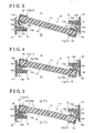
- Fig. 4 is a schematic plan view illustrating the closed state of the fluid control valve according to the first embodiment disclosed here;
- Fig. 5 is a schematic plan view illustrating the fluid control valve in a first state of the closed state
- Fig. 6 is a schematic plan view illustrating the fluid control valve in a second state of the closed state
- Fig. 7 is a schematic plan view illustrating a main portion of a fluid control valve according to a second embodiment disclosed here.
- Fig. 8 is a schematic plan view illustrating a main portion of a known fluid control valve.
- Fig. 1 shows a relationship between an intake system 1 of a V-type six-cylinder engine and six cylinders C1 to C6.
- the intake system 1 includes an intake passage 3 to which an intake air 30 is supplied via an air filter and a surge tank 5 provided between the intake passage 3 and the cylinders C1 to C6.
- a throttle valve 2 is provided at the intake passage 3.
- the surge tank 5 is divided into a first surge chamber 7a and a second surge chamber 7b by a partition wall 6. Odd numbered cylinders C1, C3, C5 are provided extending from the first surge chamber 7a shown in an upper portion in Fig. 1 . Even numbered cylinders C2, C4, C6 are provided extending from the second surge chamber 7b shown in a lower portion in Fig. 1 .
- a portion of the partition wall 6 is open and serves as a fluid passage 6P.
- a fluid control valve 10 provided at the fluid passage 6P is actuated by an actuator 20 to rotate between an open position and a closed position to change a resonance frequency of the intake system, thus attaining supercharging effects in a wide engine driving range to enhance an engine output.
- An electric control type actuator which is actuated by an electric signal sent from an electronic control unit (ECU) may be applied as the actuator 20.
- the fluid control valve 10 includes a body 12 positioned at the fluid passage 6P of the partition wall 6 and a valve body 14 supported by a shaft 15.
- the shaft 15 is pivotally supported by a part of the body 12.
- the body 12 is configured to have a window frame shape extending along an entire periphery of an opening of the partition wall 6.
- a sealing portion 13, which extends in the fluid passage 6P, is formed on an inner surface of the body 12.
- the sealing portion 13 is formed in an approximately entire periphery of the body 12.
- a solid line in Fig. 2 shows the open position of the valve body 14 and a two dotted line in Fig. 2 shows the closed position of the valve body 14.
- the valve body 14 includes a valve main body 16 made from a resin plate and attached to the shaft 15, and an elastic sealing member 17 made of an elastic member, for example, rubber, and positioned at a rim of the valve main body 16.
- the elastic sealing member 17 includes a first elastic sealing member 17A positioned at the first surge chamber 7a side and a second elastic sealing member 17B positioned at the second surge chamber 7b side.
- Each of the elastic sealing members 17A, 17B includes an attaching portion 18 configured to be outfitted to an outer periphery of the valve main body 16 and a lip portion 19 provided to protrude from a part of a rim portion of the attaching portion 18 to incline towards a center portion of the valve body 14 in a direction to be away from the valve main body 16.
- the lip portion 19 is provided to protrude from a part of an outer periphery surface of the attaching portion 18 (e.g., a corner portion 18x in an approximately U-shaped cross-section taken along a rotational direction of the valve main body 16) to incline towards the center portion of the valve body 14. In a state where the valve body 14 is at the closed position, the lip portion 19 contacts the sealing portion 13.
- the sealing portion 13 includes sealing surfaces 13a, 13b configured to receive the lip portion 19.
- the sealing surfaces 13a, 13b are formed to have an angle ⁇ relative to an imaginary plane surface which is drawn through the center of the separator partition wall 6.
- the sealing surfaces 13a, 13b are inclined surfaces declining from an outer periphery thereof to an inside, that is, the sealing surfaces 13a, 13b gradually decline towards the fluid passage 6P to face the surface of the valve main body 16 when the valve body 14 is closed so that a portion of the sealing surfaces 13a, 13b is positioned closer to the surface chambers 7a, 7b at the opposite sides, respectively, to which the respective sealing surfaces 13a, 13b do not face as a portion of the sealing surfaces 13a, 13b is positioned closer to the center of the valve body 14.
- the lip portion 19 includes a base portion 19a formed in a standing manner from the corner portion 18x of the attaching portion 18 towards an inner side of the valve body 14 and a tip end portion 19b formed inclining from an end of the base portion 19a in a direction to be away from the center portion of the valve 14.
- the lip portion 19 is shaped in a bent configuration.
- a protruding portion provided at an intermediate position between the base portion 19a and the tip end portion 19b serves as a first contact portion 19c which is configured to contact a part of the elastic sealing member 17A, 17B after the tip end portion 19b contacts the sealing surfaces 13a, 13b by an operational force of the actuator 20.
- a bent portion 19d which has a thinner thickness and is configured to be bent more readily than the base portion 19a, is provided at a portion in the vicinity of a boarder between the base portion 19a and the attaching portion 18.
- a second contact portion 18p which has a thickness thicker than other portions of the attaching portion 18 is formed on a portion of the attaching portion 18 which faces the lip portion 19.
- the first contact portion 19c of the lip portion 19 contacts the second contact portion 18p by a reaction force from the sealing surfaces 13a, 13b when the fluid control valve 10 is pressed to the sealing surfaces 13a, 13b by a gas pressure from either one of the first and second surge chambers 7a, 7b in a case where the fluid control valve 10 is at the closed position.
- valve body 14 When closing the fluid passage 6P, the valve body 14 is rotated in a counterclockwise direction by the actuator 20 to the closed position as indicated with a two-dotted line in Fig. 2 .
- the fluid passage 6P is assumed to be a state immediately after the tip end of the lip portion 19 starts contacting the sealing surface 13a, 13b (i.e., a contact starting position) as shown in Fig. 3 .
- the base portion 19a and the tip end portion 19b are positioned to lean outwardly compared to a vertical direction relative to the sealing surface 13a, 13b.
- the bent portion 19d which is adjacent to the base portion 19a is most readily to bent. Accordingly, when the valve body 14 is further rotated in the counterclockwise direction, the tip end portion 19b always moves inwardly towards the center portion of the valve body 14 in a manner declining a slope of the sealing surface 13a, 13b (i.e., arrowed directions in Fig. 3 ) without displacing outward to the base side of the sealing portion 13. In consequence, the lip portion 19 is bent to rotate about the bent portion 19d in the counterclockwise direction so as to approach the center portion of the valve body 14 by the reaction force that the tip end portion 19b receives from the sealing surface 13a, 13b.
- a pressure is applied to the bent portion 19d.
- the pressure applied to the bent portion 19d assists the inward movement of the lip portion 19 towards the center portion of the valve body 14. Accordingly, a sealing performance is enhanced by the pressure applied to the bent portion 19d after the tip end portion 19b of the lip portion 19 comes to contact the sealing surface 13a, 13b until a completion of the movement of the valve body 14 to the closed position shown in Fig. 4 .
- the lip portion 19 positioned at a left side in Fig. 3 is pressed by the pressures in a direction that the first contact portion 19c comes to closer to the second contact portion 18p.
- the tip end portion 19b pressed by the pressure is further pressed to the sealing surface 13a by a reaction force when returning to an original shape from an elastically deformed state.
- a sealing performance is enhanced during a period after the tip end portion 19b of the lip portion 19 comes to contact the sealing surface 13a until the first contact portion 19c comes to contact the second contact portion 18p.
- the lip portion 19 positioned at a right side in Fig. 3 is pressed by the pressures in a direction that the first contact portion 19c in a direction to be away from the second contact portion 18p.
- the first contact portion 19c of the lip portion 19 is pushed to the second contact portion 18p of the attaching portion 18 by the operational force of the actuator 20 so as to attain a stable state as firmly contact each other and a sealed state where a circulation of a fluid (e.g., gas) between the first surge chamber 7a and the second surge chamber 7b is adequately blocked by the tip end portion 19b which is postured in a state protruding from the firmly contact portion of the first contact portion 19c of the lip portion 19 and the second contact portion 18p of the attaching portion 18.
- a fluid e.g., gas
- the lip portion 19 is formed to protrude from the corner portion 18x to incline towards the center portion of the valve body 14.
- the lip portion 19 is formed to protrude within a width range of the valve main body 16. Accordingly, a surface of the lip portion 19 facing the sealing surface 13a, 13b is exposed to the fluid passage 6P in every closed position including the normal closed position.
- Fig. 5 illustrates a state where a gas pressure from the first surge chamber 7a located at an upper portion in Fig. 5 is applied to the fluid control valve 10 (i.e., a first state).
- Fig. 6 illustrates a state where a gas pressure from the second surge chamber 7b located at a lower portion in Fig. 6 is applied to the fluid control valve 10 (i.e., a second state).
- the valve main body 16 made from the resin plate which constructs the fluid control valve 10 is elastically deformed in a curved shape arched to protrude in an upward direction in Fig. 5 by the gas pressure. That is, the first elastic sealing member 17A positioned at a left side in Fig. 5 is positioned closer to the sealing surface 13a compared to the state shown in Fig. 4 because of the gas pressure of the first surge chamber 7a. To the contrary, the second elastic sealing member 17B positioned at a right side in Fig. 5 is away from the sealing surface 13b compared to the state shown in Fig. 4 to be closer to the second surge chamber 7b by an elastic deformation of the valve main body 16.
- the tip end portion 19b protruding from the firmly contact position of the first contact portion 19c and the second contact portion 18p is elastically deformed in a direction so as to be arranged to be close to parallel with the sealing surface 13a compared to the state shown in Fig. 4 . That is, the tip end portion 19b contacts the sealing surface 13a via a surface (i.e., hereinafter referred to as the surface contact) in the state shown in Fig.
- a surface i.e., hereinafter referred to as the surface contact
- the tip end portion 19b contacts the sealing surface 13a via a line (i.e., hereinafter referred to as the line contact) in the state shown in Fig. 4 .
- a line i.e., hereinafter referred to as the line contact
- the dimension of a contacting area with the surface contact in Fig. 5 is greater than the dimension of a contacting area with the line contact in Fig. 4 , further secure sealing performance is attained in the state shown in Fig. 5 compared to the state shown in Fig. 4 because of a reaction force of the elastically deformed tip end portion 19b.
- the base portion 19a of the lip portion 19 of the second elastic sealing member 17B is restored to a position similar to a case where an external force is not applied thereto, as shown in Fig. 5 , because the second elastic sealing member 17B is away from the sealing surface 13b by the elastic deformation of the valve main body 16.
- the tip end portion 19b is in contact with the sealing surface 13b with adequate force in those circumstances, the gas pressure from the first surge chamber 7a is received by an inner side surface of the lip portion 19 to press a portion close to an apex of the tip end portion 19b to the sealing surface 13b by the gas pressure, thus sufficient sealing state is attained.
- a second embodiment of the fluid control valve will be explained as follows referring to Fig. 7 .
- Basic constructions of the fluid control valve according to the second embodiment are similar to the first embodiment. Only different constructions of the second embodiment from the first embodiment are explained and the explanations for the common structure will not be repeated.
- a configuration of the lip portion 19 does not necessarily have the bent configuration having the base portion 19a protruding from the corner portion 18x inwardly to the center portion of the valve body 14 and the tip end portion 19b continued from the end of the base portion 19a to incline in the direction to be away from the center portion of the valve body 14.
- a lip portion 29 protrudes from the corner portion 18x of the attaching portion 18 towards the center portion of the valve body 14 to have an arched shape whose apex portion is directed to the center portion of the valve body 14 as shown in Fig. 7 .
- a ventilation groove 29v may be provided at a back surface of the lip portion 29 so that the suction is unlikely caused by a negative pressure generated in a space enclosed by the outermost portion of the base portion 19a, the tip end portion 19b, and the sealing surface 13a, 13b when the outermost portion of the base portion 19a and the tip end portion 19b are simultaneously firmly pressed to the sealing surface 13a, 13b by the gas pressure.
- the ventilation groove 29v may be formed on a back surface of the lip portion 19 disclosed in the first embodiment.
- the first contact portion 19c positioned between the base portion 19a and the tip end portion 19b is configured to contact a part of the elastic sealing members 17A, 17B.
- the first contact portion 19c may be configured to contact a part of the valve main body 16 which is made from a resin plate.
- the embodiment disclosed here is applicable to a fluid control valve including a body having a fluid passage positioned in an intake system of an automobile and a sealing surface protruding to the fluid passage, a valve body configured to rotate within the fluid passage between an open position and a closed position, and an elastic sealing member positioned at a rim portion of the valve body.
- a fluid control valve includes the body 12 forming the fluid passage 6P and including the sealing surface 13a, 13b positioned in the fluid passage 6P, the valve body 14 configured to rotate between an open position and closed position within the fluid passage 6P, the elastic sealing member 17 provided at a rim portion of the valve body 14, and the lip portion 19 extended from the elastic sealing member 17 and configured to contact the sealing surface 13a, 13b when the valve body 14 is at the closed position.
- the lip portion 19 is provided at an outer peripheral surface of the elastic sealing member to incline towards a center portion of the valve body 14.
- the lip portion 19 provided at the outer peripheral surface of the elastic sealing member 17 to incline towards the center portion of the valve body 14 comes to contact the sealing surface 13a, 13b.
- a sealing function is performed by receiving the pressure force of the fluid in one of the first and second sides of the fluid passage 6P by an outer surface of the lip portion 19.
- a sealing function is performed by receiving the pressure force of the fluid in the other of the first and second sides of the fluid passage 6P by an inner surface of the lip portion 19.
- valve body 14 and the body 12 are securely sealed when the pressure is applied from either sides of the fluid passage 6P when the valve body 14 is at the closed position. Further, because the tip end portion 19b of the lip portion 19 is positioned closer to the center portion of the valve body 14 relative to the outer peripheral surface of the valve body 14, a circumferential length of the sealing is reduced and a flow of the air can be effectively blocked even if the operational force which retains the valve body 14 at the closed position is relatively small.
- the fluid control valve does not include an outwardly extended lip portion which is clear from a construction that the lip portion 19 is formed at the outer peripheral surface of the elastic sealing member 17 to incline towards the center portion of the valve body 14 and includes the lip portion 19 inwardly extended from the rim portion of the valve body 14 towards the center portion of the valve body 14. According to this construction, because the lip portion 19 is unlikely to be sucked to the sealing surface 13a, 13b, a switching operation from the closed position to the open position is smoothly performed with a relatively small operational force.
- the lip portion 19 is retained at a state being positioned between the sealing surface 13a, 13b and the valve body 14, even if the lip portion 19 is firmly pressed to the sealing surface 13a, 13b by the pressure generated in one of the first and second sides of the fluid passage 6P, a particular portion of the lip portion 19 is unlikely damaged because of an excessive deformation.
Landscapes
- Engineering & Computer Science (AREA)
- General Engineering & Computer Science (AREA)
- Mechanical Engineering (AREA)
- Combustion & Propulsion (AREA)
- Chemical & Material Sciences (AREA)
- Manufacturing & Machinery (AREA)
- Characterised By The Charging Evacuation (AREA)
- Check Valves (AREA)
- Lift Valve (AREA)
- Sealing Using Fluids, Sealing Without Contact, And Removal Of Oil (AREA)
- Sealing Devices (AREA)
- Sealing With Elastic Sealing Lips (AREA)
- Taps Or Cocks (AREA)
Applications Claiming Priority (1)
| Application Number | Priority Date | Filing Date | Title |
|---|---|---|---|
| JP2010138384A JP5610201B2 (ja) | 2010-06-17 | 2010-06-17 | 流体制御弁 |
Publications (3)
| Publication Number | Publication Date |
|---|---|
| EP2397730A2 true EP2397730A2 (de) | 2011-12-21 |
| EP2397730A3 EP2397730A3 (de) | 2013-11-06 |
| EP2397730B1 EP2397730B1 (de) | 2017-03-08 |
Family
ID=44117831
Family Applications (1)
| Application Number | Title | Priority Date | Filing Date |
|---|---|---|---|
| EP11166709.3A Active EP2397730B1 (de) | 2010-06-17 | 2011-05-19 | Flussregelventil |
Country Status (4)
| Country | Link |
|---|---|
| US (1) | US8714522B2 (de) |
| EP (1) | EP2397730B1 (de) |
| JP (1) | JP5610201B2 (de) |
| CN (1) | CN102287272B (de) |
Families Citing this family (23)
| Publication number | Priority date | Publication date | Assignee | Title |
|---|---|---|---|---|
| JP5641361B2 (ja) | 2011-12-14 | 2014-12-17 | アイシン精機株式会社 | バタフライバルブの気密保持構造 |
| FR2990743B1 (fr) * | 2012-05-15 | 2014-05-02 | Valeo Sys Controle Moteur Sas | Vanne de controle moteur a etancheite amelioree |
| US20140027660A1 (en) * | 2012-07-24 | 2014-01-30 | Field Controls, Llc | Low leakage flue damper |
| EP2728158B1 (de) * | 2012-11-01 | 2019-01-23 | Aisin Seiki Kabushiki Kaisha | Einlasskrümmer mit einem Lufteinlass-Steuerventil |
| US9121375B2 (en) * | 2012-11-01 | 2015-09-01 | Aisin Seiki Kabushiki Kaisha | Air intake control valve and air intake apparatus |
| JP5983343B2 (ja) * | 2012-11-20 | 2016-08-31 | アイシン精機株式会社 | 吸気制御弁および吸気装置 |
| JP2014152618A (ja) * | 2013-02-05 | 2014-08-25 | Denso Corp | 吸気装置 |
| JP5858013B2 (ja) * | 2013-08-08 | 2016-02-10 | 株式会社デンソー | 吸気システム |
| JP6337539B2 (ja) * | 2014-03-18 | 2018-06-06 | アイシン精機株式会社 | 吸気制御弁および吸気装置 |
| FR3025014B1 (fr) * | 2014-08-25 | 2016-09-30 | Valeo Systemes De Controle Moteur | Vanne de controle moteur dans un vehicule automobile |
| DE102015204511A1 (de) * | 2015-03-12 | 2016-09-15 | Mahle International Gmbh | Klappenanordnung |
| JP2016217198A (ja) * | 2015-05-15 | 2016-12-22 | アイシン精機株式会社 | 吸気装置および弁体を用いたシール構造 |
| DE102015108914B4 (de) * | 2015-06-05 | 2022-11-10 | Dietrich Denker | Vorrichtung zur Absenkung von Strömungsgeräuschen |
| CN104895682A (zh) * | 2015-06-26 | 2015-09-09 | 芜湖创智机械技术有限公司 | 一种高密封型汽车节气门 |
| DE102015112717B4 (de) * | 2015-08-03 | 2021-01-14 | Dietrich Denker | Vorrichtung zur Absenkung von Strömungsgeräuschen |
| JP6634572B2 (ja) * | 2016-05-13 | 2020-01-22 | 株式会社テージーケー | バタフライバルブ |
| JP6825310B2 (ja) * | 2016-11-07 | 2021-02-03 | アイシン精機株式会社 | 吸気装置および弁体の製造方法 |
| JP6695816B2 (ja) * | 2017-02-23 | 2020-05-20 | 株式会社豊田自動織機 | 流路切替弁 |
| CN108799518B (zh) * | 2018-08-29 | 2024-07-02 | 致和环境科技(江苏)有限公司 | 方形蝶阀 |
| JP7107237B2 (ja) * | 2019-01-30 | 2022-07-27 | 株式会社デンソー | バタフライバルブ |
| CN109737211B (zh) * | 2019-03-01 | 2024-11-08 | 郑荣俊 | 阀门密封结构及密闭风阀 |
| JP2021102982A (ja) * | 2019-12-25 | 2021-07-15 | 愛三工業株式会社 | バルブ装置 |
| WO2022002370A1 (de) * | 2020-06-30 | 2022-01-06 | Adams Gmbh | Klappenventil |
Citations (1)
| Publication number | Priority date | Publication date | Assignee | Title |
|---|---|---|---|---|
| JP2003184582A (ja) | 2001-12-19 | 2003-07-03 | Aisan Ind Co Ltd | 絞り弁 |
Family Cites Families (18)
| Publication number | Priority date | Publication date | Assignee | Title |
|---|---|---|---|---|
| US2923523A (en) * | 1957-02-08 | 1960-02-02 | Wendell Coffee | Butterfly valve |
| US3457849A (en) * | 1968-02-14 | 1969-07-29 | Milton Hinden | Motorized damper assembly for ducts of varying widths |
| US3606245A (en) * | 1969-06-30 | 1971-09-20 | Ruskin Mfg Co | Control damper |
| JPS5275119U (de) * | 1975-12-03 | 1977-06-04 | ||
| JPS5357524A (en) * | 1976-11-04 | 1978-05-24 | Masafumi Isobe | Butterfly damper providing cushion |
| US4193605A (en) * | 1978-05-05 | 1980-03-18 | American Hardware & Paint Co., Inc. | Seal for damper blades |
| JPS55161170U (de) * | 1979-05-07 | 1980-11-19 | ||
| JPH04312270A (ja) * | 1991-04-05 | 1992-11-04 | Nippondenso Co Ltd | ダンパシール装置 |
| JPH05280379A (ja) * | 1992-03-30 | 1993-10-26 | Hitachi Ltd | 流量制御弁 |
| ES2067342T3 (es) | 1993-09-22 | 1995-03-16 | Siemens Ag | Procedimiento para la fabricacion de una instalacion de calefaccion y/o de aire acondicionado con una valvula de aire de chapaleta apoyada hermeticamente contra una pared de la caja, en especial para un automovil. |
| JPH07279696A (ja) * | 1994-04-12 | 1995-10-27 | Mikuni Corp | スロットル弁 |
| JP4300340B2 (ja) | 2000-02-14 | 2009-07-22 | 株式会社デンソー | 通風路切替用ドア |
| JP2002235545A (ja) * | 2001-02-09 | 2002-08-23 | Mikuni Corp | 多気筒エンジンの吸気装置 |
| US6540604B1 (en) * | 2001-09-20 | 2003-04-01 | Visteon Global Technologies, Inc. | Apparatus for directing air flow to a passenger compartment of a motor vehicle |
| FR2856128B1 (fr) * | 2003-06-10 | 2006-12-29 | Mark Iv Systemes Moteurs Sa | Dispositif a clapet et ensemble de regulation multivoies comprenant plusieurs tels dispositifs |
| US7137614B2 (en) | 2003-10-15 | 2006-11-21 | Aisan Kogyo Kabushiki Kaisha | Valve devices for controlling flow of intake air |
| JP2008075827A (ja) | 2006-09-25 | 2008-04-03 | Denso Corp | 流体制御弁 |
| FR2918145B1 (fr) | 2007-06-29 | 2016-09-30 | Valeo Systemes De Controle Moteur | Vanne a volet pourvu d'une surface peripherique d'appui |
-
2010
- 2010-06-17 JP JP2010138384A patent/JP5610201B2/ja active Active
-
2011
- 2011-05-03 US US13/099,757 patent/US8714522B2/en active Active
- 2011-05-19 EP EP11166709.3A patent/EP2397730B1/de active Active
- 2011-06-09 CN CN201110159710.5A patent/CN102287272B/zh active Active
Patent Citations (1)
| Publication number | Priority date | Publication date | Assignee | Title |
|---|---|---|---|---|
| JP2003184582A (ja) | 2001-12-19 | 2003-07-03 | Aisan Ind Co Ltd | 絞り弁 |
Also Published As
| Publication number | Publication date |
|---|---|
| US8714522B2 (en) | 2014-05-06 |
| CN102287272A (zh) | 2011-12-21 |
| EP2397730A3 (de) | 2013-11-06 |
| CN102287272B (zh) | 2015-12-16 |
| US20110308640A1 (en) | 2011-12-22 |
| EP2397730B1 (de) | 2017-03-08 |
| JP2012002291A (ja) | 2012-01-05 |
| JP5610201B2 (ja) | 2014-10-22 |
Similar Documents
| Publication | Publication Date | Title |
|---|---|---|
| EP2397730A2 (de) | Flussregelventil | |
| JP5255922B2 (ja) | 内燃機関の可変吸気装置 | |
| CN102713289B (zh) | 压缩机 | |
| JP5045869B2 (ja) | リップタイプシール | |
| CN1573023A (zh) | 轴密封机构 | |
| CN1283945C (zh) | 簧片阀或簧片阀组件 | |
| EP2249041B1 (de) | Flügelzellen-Vakuumpumpe mit einem Öl-Entlastungsventil | |
| JPH109136A (ja) | 圧縮機 | |
| CN1382908A (zh) | 一种用于压缩机壳体的密封结构 | |
| US20140161647A1 (en) | Vacuum pump for use in the automotive sector | |
| US20180120869A1 (en) | Unit for the regulation or control of a fluid pressure | |
| JP2011047373A (ja) | エンジンのセンサロータ配設構造 | |
| CN1654860A (zh) | 隔膜单元 | |
| JP5725326B2 (ja) | 吸気制御弁 | |
| US20110290348A1 (en) | Compressor Valve Plate Device | |
| JP2003526756A (ja) | シフトドラム | |
| JP5270522B2 (ja) | 内燃機関の可変圧縮比機構 | |
| KR100823066B1 (ko) | 다이어프램형 펌프 | |
| JP5359896B2 (ja) | 内燃機関の可変圧縮比機構 | |
| JP5252206B2 (ja) | 内燃機関用ウォータポンプ | |
| JP2561684Y2 (ja) | 圧縮機における弁構造 | |
| JP2011190698A (ja) | スロットル弁装置 | |
| US20130134683A1 (en) | Gasket for vehicle | |
| KR101290633B1 (ko) | 압축기 가스켓의 실링구조 | |
| JP2002242838A (ja) | 圧縮機 |
Legal Events
| Date | Code | Title | Description |
|---|---|---|---|
| AK | Designated contracting states |
Kind code of ref document: A2 Designated state(s): AL AT BE BG CH CY CZ DE DK EE ES FI FR GB GR HR HU IE IS IT LI LT LU LV MC MK MT NL NO PL PT RO RS SE SI SK SM TR |
|
| AX | Request for extension of the european patent |
Extension state: BA ME |
|
| PUAI | Public reference made under article 153(3) epc to a published international application that has entered the european phase |
Free format text: ORIGINAL CODE: 0009012 |
|
| PUAL | Search report despatched |
Free format text: ORIGINAL CODE: 0009013 |
|
| AK | Designated contracting states |
Kind code of ref document: A3 Designated state(s): AL AT BE BG CH CY CZ DE DK EE ES FI FR GB GR HR HU IE IS IT LI LT LU LV MC MK MT NL NO PL PT RO RS SE SI SK SM TR |
|
| AX | Request for extension of the european patent |
Extension state: BA ME |
|
| RIC1 | Information provided on ipc code assigned before grant |
Ipc: F02B 27/02 20060101ALI20131002BHEP Ipc: F02M 35/116 20060101ALI20131002BHEP Ipc: F02D 9/10 20060101ALI20131002BHEP Ipc: F16K 1/226 20060101AFI20131002BHEP Ipc: F02M 35/10 20060101ALI20131002BHEP |
|
| 17P | Request for examination filed |
Effective date: 20140424 |
|
| RBV | Designated contracting states (corrected) |
Designated state(s): AL AT BE BG CH CY CZ DE DK EE ES FI FR GB GR HR HU IE IS IT LI LT LU LV MC MK MT NL NO PL PT RO RS SE SI SK SM TR |
|
| 17Q | First examination report despatched |
Effective date: 20150807 |
|
| GRAP | Despatch of communication of intention to grant a patent |
Free format text: ORIGINAL CODE: EPIDOSNIGR1 |
|
| INTG | Intention to grant announced |
Effective date: 20161006 |
|
| GRAS | Grant fee paid |
Free format text: ORIGINAL CODE: EPIDOSNIGR3 |
|
| GRAA | (expected) grant |
Free format text: ORIGINAL CODE: 0009210 |
|
| AK | Designated contracting states |
Kind code of ref document: B1 Designated state(s): AL AT BE BG CH CY CZ DE DK EE ES FI FR GB GR HR HU IE IS IT LI LT LU LV MC MK MT NL NO PL PT RO RS SE SI SK SM TR |
|
| REG | Reference to a national code |
Ref country code: GB Ref legal event code: FG4D |
|
| REG | Reference to a national code |
Ref country code: CH Ref legal event code: EP Ref country code: AT Ref legal event code: REF Ref document number: 873837 Country of ref document: AT Kind code of ref document: T Effective date: 20170315 |
|
| REG | Reference to a national code |
Ref country code: IE Ref legal event code: FG4D |
|
| REG | Reference to a national code |
Ref country code: FR Ref legal event code: PLFP Year of fee payment: 7 |
|
| REG | Reference to a national code |
Ref country code: DE Ref legal event code: R096 Ref document number: 602011035631 Country of ref document: DE |
|
| REG | Reference to a national code |
Ref country code: LT Ref legal event code: MG4D |
|
| REG | Reference to a national code |
Ref country code: NL Ref legal event code: MP Effective date: 20170308 |
|
| PG25 | Lapsed in a contracting state [announced via postgrant information from national office to epo] |
Ref country code: NO Free format text: LAPSE BECAUSE OF FAILURE TO SUBMIT A TRANSLATION OF THE DESCRIPTION OR TO PAY THE FEE WITHIN THE PRESCRIBED TIME-LIMIT Effective date: 20170608 Ref country code: HR Free format text: LAPSE BECAUSE OF FAILURE TO SUBMIT A TRANSLATION OF THE DESCRIPTION OR TO PAY THE FEE WITHIN THE PRESCRIBED TIME-LIMIT Effective date: 20170308 Ref country code: GR Free format text: LAPSE BECAUSE OF FAILURE TO SUBMIT A TRANSLATION OF THE DESCRIPTION OR TO PAY THE FEE WITHIN THE PRESCRIBED TIME-LIMIT Effective date: 20170609 Ref country code: FI Free format text: LAPSE BECAUSE OF FAILURE TO SUBMIT A TRANSLATION OF THE DESCRIPTION OR TO PAY THE FEE WITHIN THE PRESCRIBED TIME-LIMIT Effective date: 20170308 Ref country code: LT Free format text: LAPSE BECAUSE OF FAILURE TO SUBMIT A TRANSLATION OF THE DESCRIPTION OR TO PAY THE FEE WITHIN THE PRESCRIBED TIME-LIMIT Effective date: 20170308 |
|
| REG | Reference to a national code |
Ref country code: AT Ref legal event code: MK05 Ref document number: 873837 Country of ref document: AT Kind code of ref document: T Effective date: 20170308 |
|
| PG25 | Lapsed in a contracting state [announced via postgrant information from national office to epo] |
Ref country code: SE Free format text: LAPSE BECAUSE OF FAILURE TO SUBMIT A TRANSLATION OF THE DESCRIPTION OR TO PAY THE FEE WITHIN THE PRESCRIBED TIME-LIMIT Effective date: 20170308 Ref country code: BG Free format text: LAPSE BECAUSE OF FAILURE TO SUBMIT A TRANSLATION OF THE DESCRIPTION OR TO PAY THE FEE WITHIN THE PRESCRIBED TIME-LIMIT Effective date: 20170608 Ref country code: LU Free format text: LAPSE BECAUSE OF NON-PAYMENT OF DUE FEES Effective date: 20170531 Ref country code: LV Free format text: LAPSE BECAUSE OF FAILURE TO SUBMIT A TRANSLATION OF THE DESCRIPTION OR TO PAY THE FEE WITHIN THE PRESCRIBED TIME-LIMIT Effective date: 20170308 Ref country code: RS Free format text: LAPSE BECAUSE OF FAILURE TO SUBMIT A TRANSLATION OF THE DESCRIPTION OR TO PAY THE FEE WITHIN THE PRESCRIBED TIME-LIMIT Effective date: 20170308 Ref country code: ES Free format text: LAPSE BECAUSE OF FAILURE TO SUBMIT A TRANSLATION OF THE DESCRIPTION OR TO PAY THE FEE WITHIN THE PRESCRIBED TIME-LIMIT Effective date: 20170308 |
|
| PG25 | Lapsed in a contracting state [announced via postgrant information from national office to epo] |
Ref country code: NL Free format text: LAPSE BECAUSE OF FAILURE TO SUBMIT A TRANSLATION OF THE DESCRIPTION OR TO PAY THE FEE WITHIN THE PRESCRIBED TIME-LIMIT Effective date: 20170308 |
|
| PG25 | Lapsed in a contracting state [announced via postgrant information from national office to epo] |
Ref country code: IT Free format text: LAPSE BECAUSE OF FAILURE TO SUBMIT A TRANSLATION OF THE DESCRIPTION OR TO PAY THE FEE WITHIN THE PRESCRIBED TIME-LIMIT Effective date: 20170308 Ref country code: AT Free format text: LAPSE BECAUSE OF FAILURE TO SUBMIT A TRANSLATION OF THE DESCRIPTION OR TO PAY THE FEE WITHIN THE PRESCRIBED TIME-LIMIT Effective date: 20170308 Ref country code: EE Free format text: LAPSE BECAUSE OF FAILURE TO SUBMIT A TRANSLATION OF THE DESCRIPTION OR TO PAY THE FEE WITHIN THE PRESCRIBED TIME-LIMIT Effective date: 20170308 Ref country code: CZ Free format text: LAPSE BECAUSE OF FAILURE TO SUBMIT A TRANSLATION OF THE DESCRIPTION OR TO PAY THE FEE WITHIN THE PRESCRIBED TIME-LIMIT Effective date: 20170308 Ref country code: SK Free format text: LAPSE BECAUSE OF FAILURE TO SUBMIT A TRANSLATION OF THE DESCRIPTION OR TO PAY THE FEE WITHIN THE PRESCRIBED TIME-LIMIT Effective date: 20170308 Ref country code: RO Free format text: LAPSE BECAUSE OF FAILURE TO SUBMIT A TRANSLATION OF THE DESCRIPTION OR TO PAY THE FEE WITHIN THE PRESCRIBED TIME-LIMIT Effective date: 20170308 |
|
| PG25 | Lapsed in a contracting state [announced via postgrant information from national office to epo] |
Ref country code: PT Free format text: LAPSE BECAUSE OF FAILURE TO SUBMIT A TRANSLATION OF THE DESCRIPTION OR TO PAY THE FEE WITHIN THE PRESCRIBED TIME-LIMIT Effective date: 20170710 Ref country code: SM Free format text: LAPSE BECAUSE OF FAILURE TO SUBMIT A TRANSLATION OF THE DESCRIPTION OR TO PAY THE FEE WITHIN THE PRESCRIBED TIME-LIMIT Effective date: 20170308 Ref country code: PL Free format text: LAPSE BECAUSE OF FAILURE TO SUBMIT A TRANSLATION OF THE DESCRIPTION OR TO PAY THE FEE WITHIN THE PRESCRIBED TIME-LIMIT Effective date: 20170308 Ref country code: IS Free format text: LAPSE BECAUSE OF FAILURE TO SUBMIT A TRANSLATION OF THE DESCRIPTION OR TO PAY THE FEE WITHIN THE PRESCRIBED TIME-LIMIT Effective date: 20170708 |
|
| REG | Reference to a national code |
Ref country code: DE Ref legal event code: R097 Ref document number: 602011035631 Country of ref document: DE |
|
| REG | Reference to a national code |
Ref country code: CH Ref legal event code: PL |
|
| PLBE | No opposition filed within time limit |
Free format text: ORIGINAL CODE: 0009261 |
|
| STAA | Information on the status of an ep patent application or granted ep patent |
Free format text: STATUS: NO OPPOSITION FILED WITHIN TIME LIMIT |
|
| PG25 | Lapsed in a contracting state [announced via postgrant information from national office to epo] |
Ref country code: DK Free format text: LAPSE BECAUSE OF FAILURE TO SUBMIT A TRANSLATION OF THE DESCRIPTION OR TO PAY THE FEE WITHIN THE PRESCRIBED TIME-LIMIT Effective date: 20170308 Ref country code: MC Free format text: LAPSE BECAUSE OF FAILURE TO SUBMIT A TRANSLATION OF THE DESCRIPTION OR TO PAY THE FEE WITHIN THE PRESCRIBED TIME-LIMIT Effective date: 20170308 |
|
| 26N | No opposition filed |
Effective date: 20171211 |
|
| REG | Reference to a national code |
Ref country code: IE Ref legal event code: MM4A |
|
| GBPC | Gb: european patent ceased through non-payment of renewal fee |
Effective date: 20170608 |
|
| PG25 | Lapsed in a contracting state [announced via postgrant information from national office to epo] |
Ref country code: LI Free format text: LAPSE BECAUSE OF NON-PAYMENT OF DUE FEES Effective date: 20170531 Ref country code: SI Free format text: LAPSE BECAUSE OF FAILURE TO SUBMIT A TRANSLATION OF THE DESCRIPTION OR TO PAY THE FEE WITHIN THE PRESCRIBED TIME-LIMIT Effective date: 20170308 Ref country code: CH Free format text: LAPSE BECAUSE OF NON-PAYMENT OF DUE FEES Effective date: 20170531 |
|
| PG25 | Lapsed in a contracting state [announced via postgrant information from national office to epo] |
Ref country code: LU Free format text: LAPSE BECAUSE OF NON-PAYMENT OF DUE FEES Effective date: 20170519 |
|
| REG | Reference to a national code |
Ref country code: FR Ref legal event code: PLFP Year of fee payment: 8 |
|
| REG | Reference to a national code |
Ref country code: BE Ref legal event code: MM Effective date: 20170531 |
|
| PG25 | Lapsed in a contracting state [announced via postgrant information from national office to epo] |
Ref country code: GB Free format text: LAPSE BECAUSE OF NON-PAYMENT OF DUE FEES Effective date: 20170608 Ref country code: IE Free format text: LAPSE BECAUSE OF NON-PAYMENT OF DUE FEES Effective date: 20170519 |
|
| PG25 | Lapsed in a contracting state [announced via postgrant information from national office to epo] |
Ref country code: BE Free format text: LAPSE BECAUSE OF NON-PAYMENT OF DUE FEES Effective date: 20170531 |
|
| PG25 | Lapsed in a contracting state [announced via postgrant information from national office to epo] |
Ref country code: MT Free format text: LAPSE BECAUSE OF NON-PAYMENT OF DUE FEES Effective date: 20170519 |
|
| PG25 | Lapsed in a contracting state [announced via postgrant information from national office to epo] |
Ref country code: HU Free format text: LAPSE BECAUSE OF FAILURE TO SUBMIT A TRANSLATION OF THE DESCRIPTION OR TO PAY THE FEE WITHIN THE PRESCRIBED TIME-LIMIT; INVALID AB INITIO Effective date: 20110519 |
|
| PG25 | Lapsed in a contracting state [announced via postgrant information from national office to epo] |
Ref country code: CY Free format text: LAPSE BECAUSE OF NON-PAYMENT OF DUE FEES Effective date: 20170308 |
|
| PG25 | Lapsed in a contracting state [announced via postgrant information from national office to epo] |
Ref country code: MK Free format text: LAPSE BECAUSE OF FAILURE TO SUBMIT A TRANSLATION OF THE DESCRIPTION OR TO PAY THE FEE WITHIN THE PRESCRIBED TIME-LIMIT Effective date: 20170308 |
|
| REG | Reference to a national code |
Ref country code: DE Ref legal event code: R084 Ref document number: 602011035631 Country of ref document: DE |
|
| PG25 | Lapsed in a contracting state [announced via postgrant information from national office to epo] |
Ref country code: TR Free format text: LAPSE BECAUSE OF FAILURE TO SUBMIT A TRANSLATION OF THE DESCRIPTION OR TO PAY THE FEE WITHIN THE PRESCRIBED TIME-LIMIT Effective date: 20170308 |
|
| PG25 | Lapsed in a contracting state [announced via postgrant information from national office to epo] |
Ref country code: AL Free format text: LAPSE BECAUSE OF FAILURE TO SUBMIT A TRANSLATION OF THE DESCRIPTION OR TO PAY THE FEE WITHIN THE PRESCRIBED TIME-LIMIT Effective date: 20170308 |
|
| REG | Reference to a national code |
Ref country code: FR Ref legal event code: PLFP Year of fee payment: 13 |
|
| PGFP | Annual fee paid to national office [announced via postgrant information from national office to epo] |
Ref country code: DE Payment date: 20250402 Year of fee payment: 15 |
|
| PGFP | Annual fee paid to national office [announced via postgrant information from national office to epo] |
Ref country code: FR Payment date: 20250401 Year of fee payment: 15 |