EP2397632A1 - Unterstützungsmechanismus für schwenkkörper - Google Patents
Unterstützungsmechanismus für schwenkkörper Download PDFInfo
- Publication number
- EP2397632A1 EP2397632A1 EP09840053A EP09840053A EP2397632A1 EP 2397632 A1 EP2397632 A1 EP 2397632A1 EP 09840053 A EP09840053 A EP 09840053A EP 09840053 A EP09840053 A EP 09840053A EP 2397632 A1 EP2397632 A1 EP 2397632A1
- Authority
- EP
- European Patent Office
- Prior art keywords
- latch
- striker
- rotational
- rotational body
- engaging
- Prior art date
- Legal status (The legal status is an assumption and is not a legal conclusion. Google has not performed a legal analysis and makes no representation as to the accuracy of the status listed.)
- Withdrawn
Links
Images






Classifications
-
- E—FIXED CONSTRUCTIONS
- E05—LOCKS; KEYS; WINDOW OR DOOR FITTINGS; SAFES
- E05F—DEVICES FOR MOVING WINGS INTO OPEN OR CLOSED POSITION; CHECKS FOR WINGS; WING FITTINGS NOT OTHERWISE PROVIDED FOR, CONCERNED WITH THE FUNCTIONING OF THE WING
- E05F1/00—Closers or openers for wings, not otherwise provided for in this subclass
- E05F1/08—Closers or openers for wings, not otherwise provided for in this subclass spring-actuated, e.g. for horizontally sliding wings
- E05F1/10—Closers or openers for wings, not otherwise provided for in this subclass spring-actuated, e.g. for horizontally sliding wings for swinging wings, e.g. counterbalance
-
- E—FIXED CONSTRUCTIONS
- E05—LOCKS; KEYS; WINDOW OR DOOR FITTINGS; SAFES
- E05F—DEVICES FOR MOVING WINGS INTO OPEN OR CLOSED POSITION; CHECKS FOR WINGS; WING FITTINGS NOT OTHERWISE PROVIDED FOR, CONCERNED WITH THE FUNCTIONING OF THE WING
- E05F1/00—Closers or openers for wings, not otherwise provided for in this subclass
- E05F1/08—Closers or openers for wings, not otherwise provided for in this subclass spring-actuated, e.g. for horizontally sliding wings
- E05F1/10—Closers or openers for wings, not otherwise provided for in this subclass spring-actuated, e.g. for horizontally sliding wings for swinging wings, e.g. counterbalance
- E05F1/1041—Closers or openers for wings, not otherwise provided for in this subclass spring-actuated, e.g. for horizontally sliding wings for swinging wings, e.g. counterbalance with a coil spring perpendicular to the pivot axis
- E05F1/1066—Closers or openers for wings, not otherwise provided for in this subclass spring-actuated, e.g. for horizontally sliding wings for swinging wings, e.g. counterbalance with a coil spring perpendicular to the pivot axis with a traction spring
-
- E—FIXED CONSTRUCTIONS
- E05—LOCKS; KEYS; WINDOW OR DOOR FITTINGS; SAFES
- E05F—DEVICES FOR MOVING WINGS INTO OPEN OR CLOSED POSITION; CHECKS FOR WINGS; WING FITTINGS NOT OTHERWISE PROVIDED FOR, CONCERNED WITH THE FUNCTIONING OF THE WING
- E05F3/00—Closers or openers with braking devices, e.g. checks; Construction of pneumatic or liquid braking devices
- E05F3/18—Closers or openers with braking devices, e.g. checks; Construction of pneumatic or liquid braking devices with counteracting springs
-
- E—FIXED CONSTRUCTIONS
- E05—LOCKS; KEYS; WINDOW OR DOOR FITTINGS; SAFES
- E05F—DEVICES FOR MOVING WINGS INTO OPEN OR CLOSED POSITION; CHECKS FOR WINGS; WING FITTINGS NOT OTHERWISE PROVIDED FOR, CONCERNED WITH THE FUNCTIONING OF THE WING
- E05F5/00—Braking devices, e.g. checks; Stops; Buffers
- E05F5/02—Braking devices, e.g. checks; Stops; Buffers specially for preventing the slamming of swinging wings during final closing movement, e.g. jamb stops
- E05F5/027—Braking devices, e.g. checks; Stops; Buffers specially for preventing the slamming of swinging wings during final closing movement, e.g. jamb stops with closing action
-
- E—FIXED CONSTRUCTIONS
- E05—LOCKS; KEYS; WINDOW OR DOOR FITTINGS; SAFES
- E05Y—INDEXING SCHEME ASSOCIATED WITH SUBCLASSES E05D AND E05F, RELATING TO CONSTRUCTION ELEMENTS, ELECTRIC CONTROL, POWER SUPPLY, POWER SIGNAL OR TRANSMISSION, USER INTERFACES, MOUNTING OR COUPLING, DETAILS, ACCESSORIES, AUXILIARY OPERATIONS NOT OTHERWISE PROVIDED FOR, APPLICATION THEREOF
- E05Y2201/00—Constructional elements; Accessories therefor
- E05Y2201/20—Brakes; Disengaging means; Holders; Stops; Valves; Accessories therefor
- E05Y2201/218—Holders
- E05Y2201/22—Locks
-
- E—FIXED CONSTRUCTIONS
- E05—LOCKS; KEYS; WINDOW OR DOOR FITTINGS; SAFES
- E05Y—INDEXING SCHEME ASSOCIATED WITH SUBCLASSES E05D AND E05F, RELATING TO CONSTRUCTION ELEMENTS, ELECTRIC CONTROL, POWER SUPPLY, POWER SIGNAL OR TRANSMISSION, USER INTERFACES, MOUNTING OR COUPLING, DETAILS, ACCESSORIES, AUXILIARY OPERATIONS NOT OTHERWISE PROVIDED FOR, APPLICATION THEREOF
- E05Y2201/00—Constructional elements; Accessories therefor
- E05Y2201/40—Motors; Magnets; Springs; Weights; Accessories therefor
- E05Y2201/404—Function thereof
- E05Y2201/41—Function thereof for closing
- E05Y2201/412—Function thereof for closing for the final closing movement
-
- E—FIXED CONSTRUCTIONS
- E05—LOCKS; KEYS; WINDOW OR DOOR FITTINGS; SAFES
- E05Y—INDEXING SCHEME ASSOCIATED WITH SUBCLASSES E05D AND E05F, RELATING TO CONSTRUCTION ELEMENTS, ELECTRIC CONTROL, POWER SUPPLY, POWER SIGNAL OR TRANSMISSION, USER INTERFACES, MOUNTING OR COUPLING, DETAILS, ACCESSORIES, AUXILIARY OPERATIONS NOT OTHERWISE PROVIDED FOR, APPLICATION THEREOF
- E05Y2201/00—Constructional elements; Accessories therefor
- E05Y2201/40—Motors; Magnets; Springs; Weights; Accessories therefor
- E05Y2201/47—Springs
- E05Y2201/488—Traction springs
-
- E—FIXED CONSTRUCTIONS
- E05—LOCKS; KEYS; WINDOW OR DOOR FITTINGS; SAFES
- E05Y—INDEXING SCHEME ASSOCIATED WITH SUBCLASSES E05D AND E05F, RELATING TO CONSTRUCTION ELEMENTS, ELECTRIC CONTROL, POWER SUPPLY, POWER SIGNAL OR TRANSMISSION, USER INTERFACES, MOUNTING OR COUPLING, DETAILS, ACCESSORIES, AUXILIARY OPERATIONS NOT OTHERWISE PROVIDED FOR, APPLICATION THEREOF
- E05Y2600/00—Mounting or coupling arrangements for elements provided for in this subclass
- E05Y2600/10—Adjustable
-
- E—FIXED CONSTRUCTIONS
- E05—LOCKS; KEYS; WINDOW OR DOOR FITTINGS; SAFES
- E05Y—INDEXING SCHEME ASSOCIATED WITH SUBCLASSES E05D AND E05F, RELATING TO CONSTRUCTION ELEMENTS, ELECTRIC CONTROL, POWER SUPPLY, POWER SIGNAL OR TRANSMISSION, USER INTERFACES, MOUNTING OR COUPLING, DETAILS, ACCESSORIES, AUXILIARY OPERATIONS NOT OTHERWISE PROVIDED FOR, APPLICATION THEREOF
- E05Y2600/00—Mounting or coupling arrangements for elements provided for in this subclass
- E05Y2600/10—Adjustable
- E05Y2600/30—Adjustment motion
- E05Y2600/33—Stepwise motion
Definitions
- the present invention relates to an improvement of a mechanism which functions so as to assist (aid) a forward movement thereof during a period from a predetermined forward-moving position to a forward-moving ending position relative to a rotational body which is moved forward toward the forward-moving ending position.
- a door closer constituted by attaching an engagement body to a door frame side, which assists a closure of a door by engaging a pin provided in the door just before the door is closed, and also by rotating due to urging means.
- a door-body closing device constituted by providing a pin on the door frame side, and by attaching an arm to a door side, which assists the closure of the door by engaging such pin, and also by rotating due to urging of a spring.
- the main problem to be solved by this invention is to ensure that a positional adjustment of a striker captured in a receiving member can be easily and appropriately carried out in this kind of assist mechanism.
- an assist mechanism for a rotational body is an assist mechanism comprising a striker provided on one of either the rotational body or a supporting body rotatably supporting this rotational body; and a receiving member provided on the other of those, moving after capturing this striker at a predetermined forward-moving position of the rotational body, and assisting a forward movement of the rotational body to a forward-moving ending position.
- the striker is supported in a striker base comprising an attachment portion relative to one of either the rotational body or the supporting body so as to be capable of adjusting a supporting position by adjusting means.
- the supporting position of the striker can be adjusted without the necessity of reattachment of the striker base, so that an inadequate disposition of the striker relative to the receiving member which is caused due to the above-mentioned misalignment and the like can be corrected.
- the supporting position of the striker in the direction approximately along the rotational direction of the rotational body can be adjusted without the necessity of the reattachment of the striker base.
- the supporting position of the striker in the direction crossing the rotational direction of the rotational body can be adjusted without the necessity of the reattachment of the striker base.
- the supporting position of the striker can be adjusted at least in two directions.
- the above-mentioned adjusting means may be structured by combining a second part, including a latch-engaging portion relative to a latch-engaged portion formed in a first part, and supported in the striker base so as to be capable of being operated to be moved from a latch-engaging position wherein the latch-engaging portion is latched and engaged with this latch-engaged portion to a non-latch-engaging position which releases this latch and engagement, with the first part including the striker and supported in the striker base so as to be capable of moving in the direction approximately along the rotational direction of the rotational body.
- at least one of the above-mentioned latch-engaging portion and the latch-engaged portion may be structured by providing in plurality in a moving direction of the first part.
- urging means against a movement toward the non-latch-engaging position of the above-mentioned second part may be further provided.
- the latch-engaging portion and the latch-engaged portion can be latched and engaged.
- the above-mentioned striker base may be structured by a main body portion supporting the striker, and a mount part including the attachment portion relative to one of either the rotational body or the supporting body, and also combined with this main body portion in a state allowing the main body portion to move in the direction crossing the rotational direction of this rotational body.
- a movable part including the latch-engaging portion relative to the latch-engaged portion formed in this mount part, and also supported in the main body portion of the striker base so as to be capable of being operated to be moved from the latch-engaging position wherein the latch-engaging portion is latched and engaged with this latch-engaged portion to the non-latch-engaging position which releases this latch and engagement, may be combined with this mount part.
- at least one of the above-mentioned latch-engaging portion and the latch-engaged portion may be structured so as to be provided in plurality in the direction crossing the rotational direction of the rotational body.
- the urging means against the movement toward the non-latch-engaging position of the movable part may be further provided.
- the latch and engagement between the above-mentioned latch-engaged portion and the latch-engaging portion can be released, and also if this operation is halted, due to the above-mentioned urging, the latch-engaging portion and the latch-engaged portion can be latched and engaged.
- the positional adjustment of the striker captured by the receiving member can be carried out without the necessity of removing a striker side, and such positional adjustment can be easily and appropriately carried out.
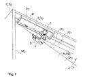
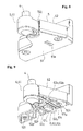
- Figs. 1 to 11 show a basic structural example of members on a striker 4 side of an assist mechanism structured by applying the present invention
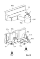
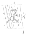
- Figs. 12 to 19(c) show a modified example of one portion of the members on this striker 4 side.
- the assist mechanism of a rotational body M functions in such a way as to assist (aid) a forward movement thereof during a period from a predetermined forward-moving position to a forward-moving ending position relative to the rotational body M which is moved forward toward the forward-moving ending position.
- Such rotational body M is supported by a supporting body F so as to be capable of rotating to a forward movement and rotating to a backward movement.
- a supporting body F so as to be capable of rotating to a forward movement and rotating to a backward movement.
- the rotational body M is not limited to the above provided that the rotational body M is supported by the supporting body F so as to be capable of rotating to the forward movement and rotating to the backward movement.
- the assist mechanism is provided in a door Ma and a door frame Fa is shown.
- the door Ma as the rotational body M blocks an opening portion Fc which is in an inward portion of the door frame Fa in a closing position (forward-moving ending position) wherein one surface Mb, which becomes the forefront at a time of the forward movement, is bumped into a doorstop portion Fb of the door frame Fa as the supporting body F. Then, if the door Ma as the rotational body M is operated to be moved forward toward the above-mentioned closing position from an open position which does not block such opening portion Fc, in a process of this forward movement, the striker 4 structuring the assist mechanism abuts against a receiving member 1 structuring the assist mechanism, and the door Ma is subjected to the action of the assist mechanism up to such closing position.
- such striker 4 is attached to a side of the door Ma as the rotational body M. Therefore, in the illustrated example, the receiving member 1 is provided on a side of the door frame Fa as the supporting body F. Incidentally, aside from the illustrated example, even if the striker 4 is attached to the side of the door frame Fa as the supporting body F, and the receiving member 1 is provided on a door Ma side as the rotational body M, the forward movement of such rotational body M can be assisted from mid-flow thereof of the forward movement.
- the striker 4 is positioned in front of one surface Mb, which becomes the forefront at the time of the forward movement in the door Ma, by a striker base 5. More specifically, in the illustrated example, such striker 4 is provided on an upper end side of the door Ma on a door hinge Mc side of the door Ma.
- the striker base 5 includes an attachment portion 5a relative to the door Ma as the rotational body M, and also supports the striker 4 in an end portion 5b positioned in front of this attachment portion 5a.
- Such striker 4 is structured as an axis-like body protruding upward from the end portion 5b of this striker base 5.
- An upper end of the striker 4 is positioned in approximately the same level as an upper end of the door Ma, or in a level slightly lower than this, and at a time of the forward movement toward the closing position of the door Ma, the striker 4 is captured by the receiving member 1 provided in a frame upper portion of the door frame Fa just before the door Ma is completely closed.
- An upper surface of the end portion of such striker base 5 is positioned in a lower portion of a level of a lower part of the after-mentioned main body 2 which rotatably houses the receiving member 1.
- the receiving member 1 is structured so as to move after capturing the striker 4 at the predetermined forward-moving position of the rotational body M, and to assist the forward movement of the rotational body M to the forward-moving ending position.
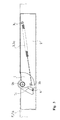
- such receiving member 1 is rotatably combined with the main body 2 so as to move between a standby position and a wrap-around position.
- Such main body 2 comprises a ceiling portion 2a as an attachment portion to the frame upper portion of the door frame Fa, and the receiving member 1 is rotatably supported in the main body 2 with a vertical axis 2b protruding downward from the ceiling portion 2a of this main body 2.
- Such receiving member 1 comprises an approximately fan-shaped outline in a state viewed from a bottom face, and also comprises an axis hole 1a relative to the above-mentioned vertical axis 2b in a main part of this fan shape.
- a capture recess 1c is formed in such a way as to be open in a fan-shaped border 1b with the above-mentioned fan shape, and also to be recessed toward an axis hole 1a side from this fan-shaped border 1b. Then, in the illustrated example, in the above-mentioned standby position, an entrance 1d of the capture recess 1c of the receiving member 1 is faced to an approaching side, i.e., a front side of the door Ma at the time of the forward movement, and also ( Fig.
- such urging means 3 is structured by a helical extension spring 3a provided in the main body 2 in such a way that one spring end 3b is fastened to a fan-shaped border 1b side of the receiving member 1, and the other spring end 3c is fastened to the main body 2, and also that a size between both these spring ends 3b, 3c reaches its maximum size in an intermediate position between the standby position and the wrap-around position of the receiving member 1. Then, such spring 3a allows to assist the forward movement of the above-mentioned door Ma, and to maintain states wherein the receiving member 1 is in the standby position and the wrap-around position.
- such spring 3a is extended the most at the above-mentioned intermediate position wherein both the spring ends 3b, 3c and the vertical axis 2b are located on the approximately same virtual straight line.
- the positive rotation of the receiving member 1 extends the above-mentioned spring 3a, and also when the receiving member 1 is in the wrap-around position, a reverse rotation of the receiving member 1 also extends the above-mentioned spring 3a. Accordingly, states wherein the receiving member 1 is in the standby position and in the wrap-around position, are respectively maintained by such spring 3a. If the above-mentioned positive rotation of the receiving member 1 is subjected to a braking force by using a damper device and the like which are not shown in the drawings, the forward movement of the assisted door Ma can be carried out slowly.
- the receiving member 1 which has captured the striker 4 is rotated reversely along with the above-mentioned backward movement up to the standby position, and if the receiving member 1 reaches the standby position, the striker 4 slips out of the capture recess 1c, and is released, so that the door Ma is allowed to move backward.
- the above-mentioned striker 4 is supported in the striker base 5 so as to be capable of adjusting a supporting position in a direction approximately along a rotational direction x of the rotational body M by an adjusting means 6.
- the striker 4 is captured by the receiving member 1, and due to the movement of the receiving member 1 after this capture, the forward movement of the door Ma toward the forward-moving ending position is assisted through the striker 4.
- assisting such forward movement cannot be realized unless the striker 4 and the receiving member 1 are respectively disposed appropriately.
- the supporting position of the striker 4 in the direction approximately along the rotational direction of the rotational body M can be adjusted without the necessity of reattachment of the striker base 5, so that an inadequate disposition of the striker 4 relative to the receiving member 1 which is caused due to the above-mentioned misalignment and the like, can be corrected.
- such adjusting means 6 is structured by combining a first part 61 including the striker 4 and a second part 62.
- the first part 61 is supported in the striker base 5 so as to be capable of moving in the direction approximately along the rotational direction x of the rotational body M.
- the second part 62 includes a latch-engaging portion 62a relative to a latch-engaged portion 61a formed in the first part 61.
- the second part 62 is supported in the striker base 5 so as to be capable of being operated to be moved from a latch-engaging position wherein the latch-engaging portion 62a is latched and engaged with this latch-engaged portion 61a to a non-latch-engaging position which releases this latch and engagement.
- the striker base 5 is structured by combining a base lower side 51 comprising a vertical attachment plate portion 51a which becomes the attachment portion 5a relative to one surface Mb of the door Ma, and a cap plate portion 51c protruding laterally from a lower border portion of this attachment plate portion 51a; and a base upper side 52 comprising a vertical plate portion 52a additionally placed in a front surface of the attachment plate portion 51a of the base lower side 51, and a case portion 52c opening a lower surface protruding forward from this vertical plate portion 52a.
- the first part 61 is housed in the case portion 52c of such base upper side 52 so as to be capable of moving back and forth. Also, the second part 62 is housed in the case portion 52c of such base upper side 52 so as to be capable of moving up and down.
- the base lower side 51 and the base upper side 52 are combined in such a way that the vertical plate portion 52a of the base upper side 52 is additionally placed in a front surface 51b of the attachment plate portion 51a of the base lower side 51, and that the lower surface of the case portion 52c of this base upper side 52 is blocked by the cap plate portion 51c of the base lower side 51.
- both are integrated by being screwed shut by using screw holes shown by symbols 51f, 52i in the drawings.
- an open portion 52j allowing the first part 61 to pass through is formed, and the first part 61 is combined with the striker base 5 in a state wherein a front end 61b side thereof is protruded forward from this open portion 52j.
- the striker 4 is provided on the front end 61b of the first part 61 protruded to an outer side of the striker base 5 through this open portion 52j in such a way as to protrude upward from there.
- first part 61 a portion ranging from an approximately intermediate position of a front-back direction thereof to a back end is divided into right and left, and the second part 62 is housed between divided right-and-left wall portions 61c, 61c so as to be capable of moving up and down.
- a compression coil spring 63a which becomes the urging means 63 is housed between an upper-portion inner surface 52h of the case portion 52c of the base upper side 52 and the second part 62.
- the second part 62 is usually positioned in the latch-engaging position wherein a lower portion 62b thereof is pressed against an inner surface 51d of the cap plate portion 51c of the base lower side 51 by this spring 63a.
- an operating convex portion 62c is formed, and also in the cap plate portion 51c of the base lower side 51, a window hole 51e with a size for only housing this operating convex portion 62c is formed.
- At least one of the above-mentioned latch-engaging portion 62a and the latch-engaged portion 61a is provided in plurality in a moving direction y of the first part 61.
- a plurality of latch-engaged portions 61a is provided in the first part 61 in the moving direction y thereof, and also a plurality of latch-engaging portions 62a is provided in the second part 62 in the moving direction y of the first part 61 as well.
- the latch-engaged portions 61a of the first part 61 are formed only on a lower side of the right-and-left wall portions 61c, 61c in an inner surface (a face on a side facing the other wall portion 61c) of the above-mentioned right-and-left wall portions 61c, 61c.
- the adjusting means 6 comprises the urging means 63 against the movement toward the non-latch-engaging position of the second part 62.
- a moving operation toward the non-latch-engaging position of the second part 62 for such adjustment can be carried out from a lower side of the striker base 5 by pushing the operating convex portion 62c by a tip of a driver and the like through the above-mentioned window hole 51e.
- a guide housing portion 52d for the first part 61 ranging from the above-mentioned open portion 52j to the vertical plate portion 52a is formed.
- the first part 61 has the minimum protruding size from the open portion 52j at a position wherein a back end thereof is bumped into an inner surface of the vertical plate portion 52a.
- convex portions 61d protruding outward from a respective outer surface are formed in the approximately intermediate position of the front-back direction of the first part 61.
- retaining portions 52e in which the convex portions 61d bump into from behind when the first part 61 is moved forward, are formed.
- the first part 61 has the maximum protruding size from the open portion 52j at a position wherein the convex portions 61d are bumped into the retaining portions 52e.
- a guide wall portion 52f is formed by leaving a space relative to the inner surface of the vertical plate portion 52a.
- the second part 62 is sandwiched between this guide wall portion 52f and the vertical plate portion 52a facing this from a back and a front so as to be capable of moving up and down.
- the second part 62 is structured so as to form a rectangle plate shape long in the front-back direction, and in both side portions on a width side thereof, grooves 62d are formed respectively in an up-and-down direction.
- ribs 52b, 52g respectively entering into the grooves 62d are formed.
- a size of the up-and-down direction in formation portions of the right-and-left wall portions 61c, 61c of the first part 61 is approximately equal to a size between the upper-portion inner surface 52h of the case portion 52c of the base upper side 52 and the inner surface 51d of the cap plate portion 51c of the base lower side 51.
- a size of the up-and-down direction of the second part 62 is approximately half the size of the up-and-down direction of the formation portions of the right-and-left wall portions 61c, 61c of the first part 61.
- the latch-engaged portions 61a of the first part 61 are formed on a lower side from an approximately intermediate position of the up-and-down direction of the above-mentioned right-and-left wall portions 61c, 61c, and the latch-engaging portions 62a of the second part 62 are formed on both side portions on a length side thereof.
- the latch-engaged portions 61a of the first part 61 are structured so as to form a rib shape respectively protruding from the inner surface of the right-and-left wall portions 61c, 61c.
- a plurality of latch-engaged portions 61a is provided by leaving an equal space between the adjacent latch-engaged portions 61a in a front-back direction respectively in the right-and-left wall portions 61c, 61c.
- Each latch-engaged portion 61a forms a rib shape with an approximately triangle mountain shape in cross section extending in the up-and-down direction.
- a rack-shaped portion 61e comprising a plurality of such latch-engaged portions 61a with a wave shape in cross-section, is formed.
- the latch-engaging portions 62a of the second part 62 are respectively structured in such a way as to form a rib shape respectively protruding from the both side portions on the length side thereof.
- a plurality of latch-engaging portions 62a is provided by leaving an equal space between the adjacent latch-engaging portions 62a in a front-back direction respectively in such both side portions.
- Each latch-engaging portion 62a forms a rib shape with an approximately triangle mountain shape in cross section extending in the up-and-down direction.
- a rack-shaped portion 62e comprising a plurality of latch-engaging portions 62a with a wave shape in cross-section, is also formed respectively.
- the rack-shaped portion 62e of the second part 62 engages the rack-shaped portion 61e of the right-and-left wall portions 61c, 61c of the first part 61, which corresponds to the above. Namely, even when the first part 61 is located in any position of the front-back direction, the second part 62 is located between the right-and-left wall portions 61c, 61c of the first part 61.
- the corresponding rack-shaped portion 62e respectively formed in the second part 62 engages the rack-shaped portion 61e formed in the right-and-left wall portions 61c, 61c of the first part 61 in such a way as to house the latch-engaging portion 62a between the neighboring latch-engaged portions 61a, 61a, and as to house the latch-engaged portion 61a between the neighboring latch-engaging portions 62a, 62a.
- the first part 61 is allowed to be stably positioned in each adjustment position thereof.
- the striker is housed in a housing hole 61f whose hole axis formed in the front end 61b of the first part 61 is formed along the up-and-down direction so as to be capable of moving in the up-and-down direction.
- the striker 4 is structured by forming a flange 4a at a lower end of a cylinder-shaped body.
- a compression coil spring 61i is installed between a cover 61h blocking a hole opening of a lower portion of the housing hole 61f and the lower end of the cylinder-shaped body structuring the striker 4.
- the striker 4 is provided in the first part 61 so as to protrude an upper portion of the flange 4a of the cylinder-shaped body from the hole opening of the upper portion of the housing hole 61f by urging of this spring 61i.
- striker base 5 is structured by a stationary-side member comprising the attachment portion 5a relative to one of either the rotational body M or the supporting body F; and a movable-side member supporting the striker 4, and also combined so as to be capable of adjusting a combinational position in a direction crossing the rotational direction x of the rotational body M relative to this stationary-side member, a positional adjustment of the striker 4 can be easily and appropriately carried out not just in the direction approximately along the rotational direction x of the rotational body M, which is in the front-back direction in the illustrated example, but also in the direction crossing the rotational direction x of this rotational body M, which is in a right-and-left direction in the illustrated example.
- the above-mentioned movable-side member is structured by the above-mentioned base upper side 52 and the base lower side 51, and also such movable-side member is combined with the stationary-side member so as to be capable of adjusting the position in the right-and-left direction, so that in the illustrated example, this stationary-side member is attached to the door Ma as the rotational body M.
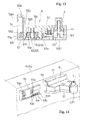
- Figs. 12 to 19(c) show the modified example of one portion wherein a main body portion 5' of the striker base 5, as such movable-side member, is provided on a rotational body M side through a mount part 53, as such stationary-side member.
- the striker base 5 is structured by the above-mentioned striker 4; the base lower side 51; the main body portion 5' comprising the base upper side 52 and the adjusting means 6; and the mount part 53.
- the attachment portion 5a relative to the rotational body M is provided in such mount part 53.
- the striker 4 is supported so as to be capable of adjusting the supporting position at least in the direction approximately along the rotational direction x of the rotational body M, and capable of adjusting the supporting position in a direction x' crossing the rotational direction x of the rotational body M by such adjusting means 6.
- the main body portion 5' of such striker base 5 is combined with the mount part 53 in a state capable of moving in the direction x' crossing the rotational direction x of the rotational body M.
- Such mount part 53 is structured in such a way as to form an approximately rectangular plate shape which is long in the right-and-left direction and short in the up-and-down direction.
- Two through holes 53a long in the up-and-down direction are provided between both ends of the right and left of this mount part 53 by leaving a space in the right-and-left direction thereof.
- the mount part 53 is fastened to the rotational body M by a screw by using the through holes 53a in a state wherein one surface side thereof is contacted with the rotational body M.
- one surface of such mount part 53 functions as the above-mentioned attachment portion 5a of the striker base 5.
- the after-mentioned latch-engaged portions 53b are formed in a front surface portion opposite to the attachment portion 5a of such mount part 53.
- the base lower side 51 differs from the basic structural examples shown in Figs. 1 to 11 , and does not include the attachment plate portion 51a.
- the base lower side 51 on a back end border of the cap plate portion 51c, the base lower side 51 comprises a pressing rib 51g protruding upward along this back end border.
- the base upper side 52 comprises a canopy-like portion 52k protruding backward along this upper end. Also, on a back end border of this canopy-like portion 52k, a pressing rib 52m protruding downward along this back end border is provided.
- a groove portion 51h housing a lower end of the vertical plate portion 52a of the base upper side 52 is formed in front of the pressing rib 51g.
- a space corresponding to a thickness of an up-and-down border portion of the mount part 53 is formed among the pressing rib 52m of the base upper side 52; the pressing rib 51g of the base lower side 51; and the vertical plate portion 52a of the base upper side 52.
- a space corresponding to a width of the mount part 53 is formed between the canopy-like portion 52k of the base upper side 52 and the cap plate portion 51c of the base lower side 51.
- this mount part 53 is fitted in a fitting space 5c of the mount part 53 formed among the pressing rib 52m of the base upper side 52; the pressing rib 51g of the base lower side 51; and the vertical plate portion 52a of the base upper side 52. Accordingly, the main body portion 5' of the striker base 5 is combined with the mount part 53 in the state capable of moving in the direction x' crossing the rotational direction x of the rotational body M. In the illustrated example, in a left side of the main body portion 5' in Fig.
- an introduction opening 5d of the mount part 53 to the fitting space 5c is formed between the pressing rib 52m of the base upper side 52 and the pressing rib 51g of the base lower side 51. Also, by sliding and moving the main body portion 5' to the left side in Fig. 14 in such a way that a right end of the mount part 53 in Fig. 14 is entered into the fitting space 5c from this introduction opening 5d, the mount part 53 and the main body portion 5' are combined. A side opposite to the introduction opening 5d in the fitting space 5c is blocked, and the main body portion 5' can slide and move toward the left side up to a position wherein the right end of the mount part 53 in Fig. 14 , which has been combined with the main body portion 5' in this manner, bumps into this blocking portion.
- the adjusting means 6 includes latch-engaging portions 62f relative to the latch-engaged portions 53b formed in this mount part 53. Also, the adjusting means 6 is structured by combining a movable part supported in the striker base 5 so as to be capable of being operated to be moved from the latch-engaging position wherein the latch-engaging portions 62f are latched and engaged with the latch-engaged portions 53b to the non-latch-engaging position which releases this latch and engagement, with the above-mentioned mount part 53.
- the latch-engaging portions 62f relative to such mount part 53 are integrally provided in the second part 62 of the basic structural example shown in Figs. 1 to 11 , and this second part 62 functions as the above-mentioned movable part.
- a split-notch portion 52n allowing inside and outside of the main body portion 5' to communicate is formed in an approximately intermediate position of a right-and-left direction in the vertical plate portion 52a of the base upper side 52. Then, through this split-notch portion 52h, a back end portion 62g of the second part 62 is entered into the above-mentioned fitting space 5c, and the above-mentioned latch-engaging portions 62f are formed in this back end portion 62g.
- the above-mentioned split-notch portion 52h is divided into right and left by one portion 52o of the vertical plate portion 52a comprising the above-mentioned rib 52b which is left in the approximately intermediate position of the right-and-left direction thereof.
- a guide hole 62h passing through the second part 62 in the up-and-down direction is formed between the back end portion 62g positioned at a back (an attachment portion 5a side) among the both side portions on the width side of the second part 62, and the operating convex portion 62c.
- the second part 62 is supported in the base upper side 52 so as to be capable of moving up and down in a state wherein one portion 52o of the above-mentioned vertical plate portion 52a is passed through this guide hole 62h.
- both of the above-mentioned latch-engaging portions 62f and the latch-engaged portions 53b are provided in plurality in the direction x' crossing the rotational direction x of the rotational body M.
- the latch-engaged portions 53b of the mount part 53 are formed in a lower border portion of the front surface portion thereof.
- Such latch-engaged portions 53b are structured in such a way as to form a rib shape protruding from the front surface portion, and a plurality of latch-engaged portions 53b is provided by leaving an equal space between the adjacent latch-engaged portions 53b in a right-and-left direction.
- Each latch-engaged portion 53b forms a rib shape whose traverse-section shape has an approximately triangle mountain shape which continues in the up-and-down direction.
- a rack-shaped portion 53c comprising a plurality of such latch-engaged portions 53b, 53b ...
- a top-to-bottom size of such latch-engaged portions 53b is approximately equal to a thickness of the second part 62, and when the second part 62 is in the latch-engaging position, the latch-engaged portions 53b are engaged with the latch-engaging portions 62f of the second part 62. However, if the second part 62 is pushed into the non-latch-engaging position, engagement of both portions is released.
- the latch-engaging portions 62f of the second part 62 are structured so as to form a rib shape protruding from the back end portion 62g thereof, and a plurality of latch-engaging portions 62f is provided by leaving an equal space between the adjacent latch-engaging portions 62f in the right-and-left direction.
- Each latch-engaging portion 62f forms a rib shape whose traverse-section shape has an approximately triangle mountain shape which continues in the up-and-down direction.
- a rack-shaped portion 62i comprising a plurality of latch-engaging portions 62f, 62f and whose traverse-section shape is wavelike, is formed as well.
- the rack-shaped portion 62i of the second part 62 is engaged with the rack-shaped portion 53c of the mount part 53.
- the corresponding rack-shaped portion 62i formed in the second part 62 engages the rack-shaped portion 53c formed in the mount part 53 in such a way as to house the latch-engaging portion 62f between the neighboring latch-engaged portions 53b, and as to house the latch-engaged portion 53b between the neighboring latch-engaging portions 62f.
- the main body portion 5' of the striker base 5 can be moved and adjusted to the direction x' crossing the rotational direction x of the rotational body M, and also is allowed to be stably positioned in each adjustment position thereof.
- the smooth moving operation in the illustrated example, the upward push-in operation
- a plurality of latch-engaging portions 62f, 62f ... of the second part 62 and a plurality of latch-engaged portions 53b, 53b ... of the mount part 53 are latched and engaged.
- the second part 62 After the main body portion 5' of the striker base 5, i.e., a supporting position of the striker 4 is adjusted to right and left by operating the second part 62 to move to the non-latch-engaging position, if this moving operation is halted, due to the urging of the spring 63a as the above-mentioned urging means 63, the second part 62 is moved to the latch-engaging position while the rack-shaped portions 62e, 62i thereof are being engaged with the rack-shaped portions 61e of the first part 61 and the rack-shaped portions 53c of the mount part 53 again.
- the striker 4 is supported in the striker base 5 so as to be capable of adjusting the supporting position in the direction approximately along the rotational direction x of the rotational body M, and also capable of adjusting the supporting position in the direction x' crossing the rotational direction x of the rotational body M by the adjusting means 6.
- a size of the right-and-left direction of this back end portion 62g i.e., a length of the rack-shaped portion 62i is increased. If the length of such rack-shaped portion 62i is elongated, a supporting positional adjustment in the right-and-left direction of the striker 4 can be carried out in a wider range.
- a cam portion 53d gradually getting higher toward a top portion 53e, which is positioned in the approximately same level of an upper end of the latch-engaged portions 53b, and forming a slope face 53f facing a left side, is formed between the latch-engaged portions 53b positioned at a left end in the rack-shaped portions 53c of the mount part 53 in Fig. 16 , and the left end of the mount part 53.
- the slope face 53f of this cam portion 53d hits against the latch-engaging portions 62f of the second part 62, and the second part 62 is pushed into the non-latch-engaging position against the urging of the above-mentioned spring 63a, so that the mount part 53 is allowed to be entered into the fitting space 5c.
- the top portion 53e of the cam portion 53d reaches a left side over the latch-engaging portions 62f which are positioned at the left end in the rack-shaped portion 62i of the second part 62 in Fig. 16
- the second part 62 is moved to the latch-engaging position by the urging of the above-mentioned spring 63a, and combining the mount part 53 with the main body portion 5' is carried out with one-touch operation.
- the left end of the mount part 53 in Figs. 19(a) to 19(c) is positioned in an opening border of the introduction opening 5d of the above-mentioned fitting space 5c.
- the supporting position of the striker 4 is adjusted to a right side rather than the standard position, and also in a case when the left end of the mount part 53 is receded from this ( Fig. 19(a) ), the completion of the supporting positional adjustment of the striker 4 to the left side rather than the standard position can be easily viewed.
Landscapes
- Lock And Its Accessories (AREA)
- Closing And Opening Devices For Wings, And Checks For Wings (AREA)
- Wing Frames And Configurations (AREA)
- Specific Sealing Or Ventilating Devices For Doors And Windows (AREA)
- Toys (AREA)
Applications Claiming Priority (3)
| Application Number | Priority Date | Filing Date | Title |
|---|---|---|---|
| JP2009029978 | 2009-02-12 | ||
| JP2009125211A JP5225199B2 (ja) | 2009-02-12 | 2009-05-25 | 回動体のアシスト機構 |
| PCT/JP2009/071485 WO2010092734A1 (ja) | 2009-02-12 | 2009-12-24 | 回動体のアシスト機構 |
Publications (2)
| Publication Number | Publication Date |
|---|---|
| EP2397632A1 true EP2397632A1 (de) | 2011-12-21 |
| EP2397632A4 EP2397632A4 (de) | 2014-06-04 |
Family
ID=42561583
Family Applications (1)
| Application Number | Title | Priority Date | Filing Date |
|---|---|---|---|
| EP09840053.4A Withdrawn EP2397632A4 (de) | 2009-02-12 | 2009-12-24 | Unterstützungsmechanismus für schwenkkörper |
Country Status (5)
| Country | Link |
|---|---|
| EP (1) | EP2397632A4 (de) |
| JP (1) | JP5225199B2 (de) |
| KR (1) | KR101254436B1 (de) |
| CN (1) | CN102317559B (de) |
| WO (1) | WO2010092734A1 (de) |
Cited By (2)
| Publication number | Priority date | Publication date | Assignee | Title |
|---|---|---|---|---|
| EP2857620A4 (de) * | 2012-06-04 | 2016-02-24 | Sugatsune Kogyo | Mechanismus zur positionierung einer unterlegscheibe und möbelstück mit installiertem mechanismus zur positionierung einer unterlegscheibe |
| EP4317871A4 (de) * | 2021-03-22 | 2025-03-19 | LG Electronics Inc. | Kühlschrank |
Families Citing this family (6)
| Publication number | Priority date | Publication date | Assignee | Title |
|---|---|---|---|---|
| SI2407625T1 (sl) * | 2011-10-05 | 2017-05-31 | V-Zug Ag | Avtomatično zapiralo vrat za gospodinjski aparat |
| JP5943600B2 (ja) * | 2011-12-27 | 2016-07-05 | パナソニック株式会社 | ポジショニング機構、及びポジショニング方法 |
| JP5874386B2 (ja) * | 2011-12-27 | 2016-03-02 | 中西金属工業株式会社 | 操作力軽減装置 |
| CN104246100B (zh) * | 2012-04-27 | 2016-06-29 | 株式会社利富高 | 门的辅助机构 |
| JP6732397B2 (ja) * | 2018-03-23 | 2020-07-29 | スガツネ工業株式会社 | 引込み装置及び引込み装置セット |
| CN119434810B (zh) * | 2025-01-10 | 2025-04-18 | 山西八建集团有限公司 | 一种镜面混凝土人防门及其使用方法 |
Family Cites Families (9)
| Publication number | Priority date | Publication date | Assignee | Title |
|---|---|---|---|---|
| JPS5569566U (de) * | 1978-11-02 | 1980-05-13 | ||
| JPH0645588Y2 (ja) * | 1990-07-23 | 1994-11-24 | コーエイ産業株式会社 | ヒンジ装置 |
| JPH0645588A (ja) * | 1992-07-23 | 1994-02-18 | Sony Corp | オーミック電極及びその形成方法 |
| JP4796816B2 (ja) * | 2005-10-28 | 2011-10-19 | 株式会社ムラコシ精工 | 扉体閉止装置 |
| JP4661592B2 (ja) * | 2005-12-27 | 2011-03-30 | 中西金属工業株式会社 | ドアクローザ |
| CN101131061B (zh) * | 2006-08-25 | 2012-01-11 | 上海科星五金有限公司 | 手摇开窗器 |
| JP2009029978A (ja) | 2007-07-30 | 2009-02-12 | Seiko Epson Corp | インクカートリッジ |
| JP2009125211A (ja) | 2007-11-21 | 2009-06-11 | Olympia:Kk | スロットマシン及び遊技システム |
| JP5377227B2 (ja) * | 2009-10-30 | 2013-12-25 | 株式会社ニフコ | 回動体のアシスト機構 |
-
2009
- 2009-05-25 JP JP2009125211A patent/JP5225199B2/ja not_active Expired - Fee Related
- 2009-12-24 KR KR1020117021404A patent/KR101254436B1/ko not_active Expired - Fee Related
- 2009-12-24 EP EP09840053.4A patent/EP2397632A4/de not_active Withdrawn
- 2009-12-24 CN CN200980156645.1A patent/CN102317559B/zh not_active Expired - Fee Related
- 2009-12-24 WO PCT/JP2009/071485 patent/WO2010092734A1/ja not_active Ceased
Cited By (2)
| Publication number | Priority date | Publication date | Assignee | Title |
|---|---|---|---|---|
| EP2857620A4 (de) * | 2012-06-04 | 2016-02-24 | Sugatsune Kogyo | Mechanismus zur positionierung einer unterlegscheibe und möbelstück mit installiertem mechanismus zur positionierung einer unterlegscheibe |
| EP4317871A4 (de) * | 2021-03-22 | 2025-03-19 | LG Electronics Inc. | Kühlschrank |
Also Published As
| Publication number | Publication date |
|---|---|
| CN102317559B (zh) | 2014-07-02 |
| KR101254436B1 (ko) | 2013-04-12 |
| WO2010092734A1 (ja) | 2010-08-19 |
| EP2397632A4 (de) | 2014-06-04 |
| JP2010209673A (ja) | 2010-09-24 |
| KR20110122845A (ko) | 2011-11-11 |
| JP5225199B2 (ja) | 2013-07-03 |
| CN102317559A (zh) | 2012-01-11 |
Similar Documents
| Publication | Publication Date | Title |
|---|---|---|
| EP2397632A1 (de) | Unterstützungsmechanismus für schwenkkörper | |
| US6905152B1 (en) | Slide bolt locking systems | |
| US8272166B2 (en) | Self-propelled forward movement mechanism of movable body and sliding door | |
| US9752355B2 (en) | Vehicle door latch device | |
| KR101086277B1 (ko) | 슬라이딩 도어용 자동잠금장치 | |
| US20040089033A1 (en) | Door lock structure | |
| JP6823142B1 (ja) | 窓開閉ロック装置 | |
| KR101958219B1 (ko) | 도어 힌지 | |
| KR101138288B1 (ko) | 회동식 창호용 스테이바 | |
| US6938302B2 (en) | Door closing mechanism | |
| RU2315846C2 (ru) | Устройство для закрывания двери | |
| KR101040999B1 (ko) | 회동식 창호용 스테이바 | |
| JP6666618B2 (ja) | 辷り出し窓の開度設定装置 | |
| KR101042192B1 (ko) | 미닫이 창문의 개폐 제어장치 | |
| JP2834115B1 (ja) | 自動ロック型錠装置 | |
| KR101115424B1 (ko) | 창호용 버튼식 자동잠금장치 | |
| KR200479071Y1 (ko) | 미닫이 도어용 잠금장치 | |
| KR100448201B1 (ko) | 자동차의 어퍼트레이 커버 잠금구조 | |
| JP3911679B2 (ja) | シャッターの錠装置及びその錠装置を備えたシャッター | |
| KR101467546B1 (ko) | 창호 | |
| KR200223979Y1 (ko) | 미닫이문의 잠금장치 | |
| JP4337068B2 (ja) | 窓のロック装置 | |
| JP3602873B2 (ja) | 機能ブロックの取付機構 | |
| JP2001311334A (ja) | 引き違い戸の鎌錠装置 | |
| JP4330544B2 (ja) | 自動閉止式の引戸 |
Legal Events
| Date | Code | Title | Description |
|---|---|---|---|
| PUAI | Public reference made under article 153(3) epc to a published international application that has entered the european phase |
Free format text: ORIGINAL CODE: 0009012 |
|
| 17P | Request for examination filed |
Effective date: 20110809 |
|
| AK | Designated contracting states |
Kind code of ref document: A1 Designated state(s): AT BE BG CH CY CZ DE DK EE ES FI FR GB GR HR HU IE IS IT LI LT LU LV MC MK MT NL NO PL PT RO SE SI SK SM TR |
|
| DAX | Request for extension of the european patent (deleted) | ||
| A4 | Supplementary search report drawn up and despatched |
Effective date: 20140508 |
|
| RIC1 | Information provided on ipc code assigned before grant |
Ipc: E05F 5/02 20060101ALI20140429BHEP Ipc: E05F 1/10 20060101AFI20140429BHEP |
|
| STAA | Information on the status of an ep patent application or granted ep patent |
Free format text: STATUS: THE APPLICATION IS DEEMED TO BE WITHDRAWN |
|
| 18D | Application deemed to be withdrawn |
Effective date: 20160701 |