EP2394943B1 - Faltvorrichtung und Bilderzeugungssystem - Google Patents
Faltvorrichtung und Bilderzeugungssystem Download PDFInfo
- Publication number
- EP2394943B1 EP2394943B1 EP11250544.1A EP11250544A EP2394943B1 EP 2394943 B1 EP2394943 B1 EP 2394943B1 EP 11250544 A EP11250544 A EP 11250544A EP 2394943 B1 EP2394943 B1 EP 2394943B1
- Authority
- EP
- European Patent Office
- Prior art keywords
- creasing
- sheet
- blade
- contact
- creasing device
- Prior art date
- Legal status (The legal status is an assumption and is not a legal conclusion. Google has not performed a legal analysis and makes no representation as to the accuracy of the status listed.)
- Not-in-force
Links
Images











Classifications
-
- B—PERFORMING OPERATIONS; TRANSPORTING
- B65—CONVEYING; PACKING; STORING; HANDLING THIN OR FILAMENTARY MATERIAL
- B65H—HANDLING THIN OR FILAMENTARY MATERIAL, e.g. SHEETS, WEBS, CABLES
- B65H45/00—Folding thin material
- B65H45/12—Folding articles or webs with application of pressure to define or form crease lines
- B65H45/30—Folding in combination with creasing, smoothing or application of adhesive
-
- G—PHYSICS
- G03—PHOTOGRAPHY; CINEMATOGRAPHY; ANALOGOUS TECHNIQUES USING WAVES OTHER THAN OPTICAL WAVES; ELECTROGRAPHY; HOLOGRAPHY
- G03G—ELECTROGRAPHY; ELECTROPHOTOGRAPHY; MAGNETOGRAPHY
- G03G15/00—Apparatus for electrographic processes using a charge pattern
- G03G15/65—Apparatus which relate to the handling of copy material
- G03G15/6555—Handling of sheet copy material taking place in a specific part of the copy material feeding path
- G03G15/6573—Feeding path after the fixing point and up to the discharge tray or the finisher, e.g. special treatment of copy material to compensate for effects from the fixing
-
- G—PHYSICS
- G03—PHOTOGRAPHY; CINEMATOGRAPHY; ANALOGOUS TECHNIQUES USING WAVES OTHER THAN OPTICAL WAVES; ELECTROGRAPHY; HOLOGRAPHY
- G03G—ELECTROGRAPHY; ELECTROPHOTOGRAPHY; MAGNETOGRAPHY
- G03G2215/00—Apparatus for electrophotographic processes
- G03G2215/00362—Apparatus for electrophotographic processes relating to the copy medium handling
- G03G2215/00789—Adding properties or qualities to the copy medium
- G03G2215/00877—Folding device
Definitions
- the present invention relates to a creasing device and an image forming system.
- the saddle-stitched booklet production is performed by saddle stitching a sheet batch, which is a stack of a plurality of sheets delivered from an image forming apparatus, and folding the thus-saddle-stitched sheet batch in the middle of the sheet batch.
- Folding such a sheet batch containing a plurality of sheets can cause outside sheets of the sheet batch to be stretched at a fold line by a greater amount than inside sheets. Image portions at the fold line on outside sheets can thus be stretched, resulting in damage, such as come off of toner, to the image portions in some cases.
- a similar phenomenon can occur when other fold, such as z-fold or trifold, is performed.
- a sheet batch can be folded insufficiently depending on the thickness of the sheet batch.
- Creasing devices that crease (score) a sheet batch prior to a folding process where the sheet batch undergoes half fold or the like to make outside sheets easy to fold, thereby preventing come off of toner have already been known.
- Some type of such creasing devices produce a crease in a sheet in a direction perpendicular to a sheet conveying direction by moving a roller on a sheet, burning a sheet with a laser beam, pressing a creasing blade against a sheet, or a like method.
- a known example of such a creasing device is disclosed in Japanese Patent Application Laid-open No. 2009-166928 .
- a technique of moving a creasing member by using a plurality of individually-advancing-and-retracting mechanisms, which are activated at different times, so that the creasing member presses a sheet with a gradually-decreasing pressure to produce a crease is disclosed in Japanese Patent Application Laid-open No. 2009-166928 .
- Creasing a sheet by pressing a creasing blade against the sheet can be performed in a relatively short period of time and allows easy production of a crease perpendicular to a sheet conveying direction; however, pressing a longitudinal face of the creasing blade against the sheet entirely at once can increase a load.
- a scheme of virtually dividing the face of the creasing blade into a plurality of portions and bringing the creasing blade face into contact with a sheet a plurality of times, one portion each time can be used.
- this scheme is disadvantageous in that unevenness can develop between a portion that contacts the blade multiple times and a portion that contacts the blade only once and also in that producing a crease by making contact multiple times can decrease productivity.
- the present invention aims at providing a technique for producing a uniform crease in a sheet with a reduced processing time.
- US2009/181840A discloses a creasing device for creasing sheets on a per-sheet basis, the creasing device comprising: a first member extending in a direction perpendicular to a sheet conveying direction and including a male blade, the male blade having a convex cross section; a second member extending in the direction perpendicular to the sheet conveying direction and including a grooved female blade, the female blade allowing the male blade to be fitted thereinto with a sheet between the female blade and the male blade; and a drive unit that brings the first member and the second member relatively into and out of contact with each other to cause a sheet stopped at a predetermined position to be pinched between the first member and the second member and creased.
- a creasing device for creasing sheets on a per-sheet basis, the creasing device including: a first member extending in a direction perpendicular to a sheet conveying direction and including a male blade, the male blade having a convex cross section and an edge portion of the male blade having an arcuate shape; a second member extending in the direction perpendicular to the sheet conveying direction and including a grooved female blade, the female blade allowing the male blade to be fitted thereinto with a sheet between the female blade and the male blade ; and a drive unit that brings the first member and the second member relatively into and out of contact with each other to cause a sheet stopped at a predetermined position to be pinched between the first member and the second member the drive unit being further arranged to cause the male blade to pivot, thereby to produce a crease in the sheet with the edge portion having on arcuate shape.
- distal-end portions of a male blade which is a creasing blade for use in creasing a sheet before the sheet is folded
- a female blade are arcuate in shape in a longitudinal direction of the blades so that the creasing blade can make a point-to-point contact with the sheet. This reduces a driving load for creasing, thereby allowing a uniform crease to be produced by a single stroke of contact.
- a reference symbol A corresponds to the creasing unit; a creasing blade 6-1 is an example of the male blade; a creasing member 6 is an example of the first member; a creasing channel 7a is an example of the female blade; a receiving member 7 is an example of the second member; a drive mechanism 40 is an example of the drive unit, a CPU A1 is an example of the control unit; a reference symbol F corresponds to the image forming apparatus.
- Fig. 1 is a diagram illustrating a schematic configuration of an image forming system according to an embodiment of the present invention.
- the image forming system according to the embodiment includes the image forming apparatus F that forms an image on a sheet of paper (hereinafter, "sheet”), the creasing device A that creases the sheet, and a folding device B folds the sheet at a predetermined position.
- sheet a sheet of paper
- the image forming apparatus F forms a visible image pertaining to image data fed from a scanner, a personal computer (PC), or the like on a sheet of paper.
- the image forming apparatus F uses a known print engine of electrophotography, droplet ejection printing, or the like.
- the creasing device A includes a conveyance path 33, first to fifth conveying rollers 1 to 5 located in this order along a forward sheet conveying direction of the conveyance path 33, an entrance sensor SN1 provided upstream of the first conveying rollers 1 at an entrance of the device for detection of a sheet, a creasing unit C provided between the third and the fourth conveying rollers 3 and 4, and a skew correcting unit E in an immediate vicinity of the creasing unit C relative to the sheet conveying direction.
- the creasing unit C includes the creasing blade 6-1, a creasing support member 6-2, the receiving member 7, a sheet retaining member 8, a resilient member(ex.
- the skew correcting unit E includes a stopper plate 30, a stopper-plate cam 31, and a conveyance guide plate 32.
- the creasing blade 6-1 and the receiving member 7 pinch a sheet therebetween to produce a crease facing the creasing blade 6-1 at its inner side.
- the folding device B includes a sheet-output conveyance path 57, a processing conveyance path 58, sixth to ninth conveying rollers 51 to 54, and a folding unit D.
- the folding unit D includes a trailing-edge fence 60, folding rollers 55, a folding plate 61, and a first stacking tray T1 and a second stacking tray T2.
- a path-switching flap 50 for use in switching conveyance between the sheet-output conveyance path 57 and the processing conveyance path 58 is provided at a branching portion into the sheet-output conveyance path 57 and the processing conveyance path 58.
- the seventh conveying rollers 52 serving as sheet output rollers are provided most downstream of the sheet-output conveyance path 57.
- the skew correcting unit E performs operations differently depending on whether skew correction is to be performed.
- Fig. 2 and Fig. 3 are schematic diagrams illustrating operations in a situation where skew correction is to be skipped.
- the stopper-plate cam 31 rotates, causing the stopper plate 30 to retract from the conveyance path 33 as illustrated in Fig. 3 .
- the sheet P is conveyed to the third conveying rollers 3 and then further conveyed toward the folding unit D downstream.
- a conveyance speed of the second conveying rollers 2 and that of the third conveying rollers 3 are equal to each other.
- Fig. 4 to Fig. 9 are schematic diagrams illustrating operations to be performed in a situation where skew correction is to be performed.
- the third conveying rollers 3 are at a standby state where the third conveying rollers 3 are released from a pressure contact as illustrated in Fig. 4 .
- the sheet P is further conveyed and caused to abut on the stopper plate 30 by the second conveying rollers 2 as illustrated in Fig. 5 , the sheet P is resiliently bent and hence subjected to skew correction.
- the third conveying rollers 3 are brought into a pressure contact as illustrated in Fig. 6 , causing the stopper plate 30 to retract from the conveyance path 33 as illustrated in Fig. 7 .
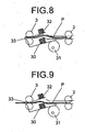
- the sheet P is conveyed downstream by the second and the third conveying rollers 2 and 3 as illustrated in Fig. 8 .
- the sheet P is conveyed only by the third conveying rollers 3 as illustrated in Fig. 9 , which straightens the resiliently-bent sheet P.
- the conveyance guide plate 32 is elevated and lowered following ascending and descending motions of one conveying roller, which is on the upper one in Fig. 4 to 9 , of the third conveying rollers 3, thereby opening and closing the conveyance path 33.
- the creasing unit C operates differently depending on whether creasing is to be performed.
- Fig. 10 to Fig. 13 are schematic explanatory diagrams of operations in a situation where the folding device B performs folding.
- Fig. 14 and Fig. 15 are schematic diagrams illustrating operations in a situation where folding is skipped.
- the sheet P After passing through the skew correcting unit E, the sheet P is conveyed to the folding apparatus B by the fourth and the fifth conveying rollers 4 and 5.
- the path-switching flap 50 When the sheet P is to be conveyed to the folding apparatus B to undergo folding, the path-switching flap 50 is in a position 50a where the path-switching flap 50 closes the sheet-output conveyance path 57 but opens the processing conveyance path 58 as illustrated in Fig. 10 .
- the sheet P is guided to the processing conveyance path 58 by the path-switching flap 50.
- the sheet P is conveyed to the folding unit D by the eighth and the ninth conveying rollers 53 and 54 and placed on the trailing-edge fence 60 as illustrated in Fig. 11 .
- the placed sheet P is conveyed (lifted up) by the trailing-edge fence 60 to a folding position.
- the sheet P is pushed into a nip between the folding rollers 55 by the folding plate 61 as illustrated in Fig. 12 , to thus be folded in the folding roller 55.
- the sheet P is delivered onto the stacking tray T1 as illustrated in Fig. 13 .
- the path-switching flap 50 is in a position 50b where the path-switching flap 50 opens the sheet-output conveyance path 57 but closes the processing conveyance path 58 as illustrated in Fig. 14 . This causes the sheet P to be delivered through the sheet-output conveyance path 57 onto the stacking tray T2 by the seventh conveying rollers 52.
- skew correction is performed on every sheet that is to undergo creasing. Note that a configuration where a user can configure settings so as to skip skew correction can be employed.
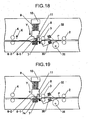
- Fig. 16 to Fig. 21 are schematic diagrams illustrating creasing operations.
- the sheet P is conveyed into the creasing unit C by the third conveying rollers 3 by a specified distance with reference to the stopper plate 30.
- the sheet P is stopped.
- the creasing blade 6-1 is lowered in a direction indicated by arrow Y as illustrated in Fig. 18 .
- an upper roller of the fourth conveying rollers 4 ascends as indicated by arrow X, releasing the fourth conveying rollers 4 from a pressure contact.
- the creasing blade 6-1 As illustrated in Fig. 19 , after the fourth conveying rollers 4 have been released from the pressure contact, the creasing blade 6-1 further descends in the direction indicated by arrow Y to pinch the sheet P with a predetermined pressure between the creasing blade 6-1 and the receiving member 7. As a result, a crease is produced in the sheet P.
- the creasing blade 6-1 ascends in a direction indicated by arrow Y'.
- the fourth conveying rollers 4 descend in a direction indicated by arrow X' to press against the sheet P again, thereby placing the sheet P in a conveyable state. Thereafter, as illustrated in Fig. 21 , the sheet P is conveyed downstream by the fourth conveying rollers 4.
- Fig. 22 is a plan view of a relevant portion of the creasing unit C
- Fig. 23 which is an elevation view (elevation view corresponding to the plan view of Fig. 22 ).
- the creasing unit C includes the creasing member 6 (the creasing blade 6-1 and the creasing support member 6-2), the receiving member 7, and the drive mechanism 40.
- the creasing member 6 has, in addition to the creasing blade 6-1 provided at a lower end of the creasing member 6, a first elongated hole R and a second elongated hole and S, into which a first support shaft 44 and a second support shaft 43, which will be described later, are to be loosely fit, respectively, and includes a first positioning member 42a and a second positioning member 42b provided at a rear end portion and a front end portion, respectively.
- the first and the second elongated holes R and S are elongated in a direction perpendicular to the sheet conveying direction as indicated by arrow Z and configured to allow the first and the second support shafts 44 and 43 to pivot relative to a plane that lies perpendicularly to the sheet conveying direction but not to allow movement in the sheet conveying direction.
- the first and the second positioning members 42a and 42b extend substantially vertically downward from a front end portion and a rear end portion of the creasing support member 6-2.
- the first and the second positioning members 42a and 42b are disciform cam followers that are rotatably supported at their centers and brought into contact with the first cam 40a and the second cam 40b to be rotated. Meanwhile, a front side of the device is depicted on the left-hand side in Fig. 22 and Fig. 23 .
- the receiving member 7 is coupled to the resilient member fixing plate 10 located above the creasing member 6 via the first and the second support shafts 44 and 43 and moved integrally with the resilient member fixing plate 10.
- a first shaft member 47a which is on a rear side
- a second shaft member 47b which is on a front side.
- a first resilient member 9a and a second resilient member 9b (which are collectively referred to as "the resilient member 9") are mounted on an outer periphery of the first shaft member 47a and an outer periphery of the second shaft member 47b, respectively and constantly resiliently urging the resilient member fixing plate 10 upward, and hence the receiving member 7 upward.
- the first support shaft 44 having a semicircular cross-sectional profile taken along short sides in a rectangular cross section is loosely fit in the first elongated hole R.
- a third elongated hole 44a that is vertically elongated is defined in the first support shaft 44 at a portion lower than a midportion of the first support shaft 44.
- a rotating shaft Q is vertically (in a direction perpendicular to the plane of Fig. 23 ) inserted into the third elongated hole 44a from a side-surface side of the creasing member 6.
- the diameter of the rotating shaft Q is set to such a dimension, relative to the width of the third elongated hole 44a, that allows the rotating shaft Q to move in Y-directions in Fig.
- the drive mechanism 40 is a mechanism that rotates the cams 40a and 40b, which are in contact with the positioning members 42a and 42b, to press the creasing member 6 against the receiving member 7 and move the creasing member 6 away from the receiving member 7.
- the drive mechanism 40 includes a camshaft 45, to which the first cam 40a and the second cam 40b are coaxially coupled at a rear portion and a front portion of the camshaft 45, respectively, a drive gear train 46, through which the camshaft 45 is driven, at an end portion (in the present embodiment, a rear end portion) of the camshaft 45, and a drive motor 41 that drives the drive gear train 46.
- the first cam 40a and the second cam 40b are located to face the first positioning member 42a and the second positioning member 42b and abutting thereon, respectively.
- the cams 40a and 40b move the creasing member 6 toward and away from the receiving member 7 according to a distance between the positioning members 42a and 42b on a straight line passing through a center of the camshaft 45 and a rotation center of the positioning members 42a and 42b.
- a range where the creasing member 6 moves is confined by each of the first and the second support shafts 44 and 43 and the first and the second elongated channels R and S.
- the creasing member 6 reciprocates under this confined state.
- a configuration that causes the creasing blade 6-1 of the creasing member 6 to come into contact with the receiving member 7 in an orientation inclined relative to the receiving member 7 rather than parallel with the receiving member 7 so that the creasing blade 6-1 oriented obliquely relative to a plane of the sheet produces a crease in the sheet according to shapes of the first and the second cams 40a and 40b is employed.
- a distal-end edge face of the creasing blade 6-1 is arcuate as illustrated in Fig. 23 .
- Fig. 24 to Fig. 29 are schematic illustrations of operations performed to crease (score) a sheet by using the creasing member 6. Creasing starts when the drive motor 41 starts running in response to an instruction fed from a control circuit (not shown).
- the camshaft 45 is rotated via the drive gear train 46, which in turn rotates the first and the second cams 40a and 40b.
- the first and the second positioning members 42a and 42b which are the cam followers that abut on the first and the second cams 40a and 40b and roll, are rotated, causing a center distance between the positioning members 42a and 42b, and the camshaft 45 to change, thereby moving the creasing member 6 in a direction indicated by Y1.
- the receiving member 7 prevents the creasing member 6 from moving farther.
- the drive motor 41 further rotates from this state, the first positioning member 42a and the first cam 42a are separated from each other.
- the second positioning member 42b is in contact with the second cam 40b because a front portion, relative to the device, of the creasing blade 6-1 of the creasing member 6 is not abutting on the receiving member 7.
- the drive motor 41 further rotates, causing the camshaft 45 and the first and the second cams 40a and 40b to rotate.
- the first positioning member 42a and the first cam 40a are brought into contact with each other earlier than the second positioning member 42b and the second cam 40b, and the first cam 40a pushes up the first positioning member 42a on a far side, moving up a far-side portion of the creasing member 6 in a direction indicated by an arrow Y2 earlier than a near-side portion of the creasing member 6.
- Fig. 27 the first positioning member 42a and the first cam 40a are brought into contact with each other earlier than the second positioning member 42b and the second cam 40b, and the first cam 40a pushes up the first positioning member 42a on a far side, moving up a far-side portion of the creasing member 6 in a direction indicated by an arrow Y2 earlier than a near-side portion of the creasing member 6.
- the bottom end of the creasing blade 6-1 on the side of the first positioning member 42a is temporarily stopped at the position separated from the receiving member 7.
- a top surface of the creasing member 6 is oriented horizontally as illustrated in Fig. 29
- the creasing member 6 ascends while maintaining the horizontal orientation to return to a standby position, or, put another way, the initial position illustrated in Fig. 25 .
- the creasing blade 6-1 is inclined such that the far side of the creasing blade 6-1 is closer to the receiving member 7 than the front side is.
- the creasing member 6 is thus constructed to have what is called a pivot center at its distal end and to produce a crease with an arcuate blade (the creasing blade 6-1) that pivots about the far side relative to the device by going through a motion similar to that of a cutter that performs cutting with a pressure exerted thereon. This motion is produced by the shapes of the first and the second cams 40a and 40b.
- Fig. 30A to Fig. 30E are schematic illustrations of operations and illustrating how positional relationship between the receiving member 7 and the creasing member 6 changes as positional relationship between the first and the second cams 40a and 40b and the first and the second positioning members 42a and 42b changes.
- Fig. 30A to Fig. 30E relationships between rotational positions of the first cam 40a and those of the first positioning member 42a on the far side relative to the device are depicted on the right-hand side; relationships between rotational positions of the second cam 40b and those of the second positioning member 42b on the front side relative to the device are depicted on the left-hand side.
- Fig. 30A illustrates a position of the creasing blade 6-1 relative to the receiving member 7 in a period where a sheet has been conveyed into the creasing device A, conveyed to a folding position, and stopped at the folding position. This position is the initial position.
- L denotes the distance from the center of the camshaft 45 of the first cam 40a to a point of contact (on an outer peripheral surface) between the first positioning member 42a and the first cam 40a on a straight line passing through the center of the camshaft 45 of the first cam 40a and the center of the rotating shaft of the first positioning member 42a.
- H denotes the distance from the center of the camshaft 45 of the second cam 40b to a point of contact (on an outer peripheral surface) between the second positioning member 42b and the second cam 40b on a straight line passing through the center of the camshaft 45 of the second cam 40b and the center of the second positioning member 42b.
- the creasing blade 6-1 and the creasing channel 7a are in the positional relationship illustrated in Fig. 24 , where a clearance between the creasing blade 6-1 and the creasing channel 7a on the far side and that on the front side are equal to each other.
- H is the distance to the point of contact of between the second cam 40b and a corresponding one of the cam followers;
- L is the distance to the point of contact of between the first cam 40a and a corresponding one of the cam followers.
- Fig. 30B illustrates relevant elements in a state where a portion A, which is a trailing-edge portion of the creasing blade 6-1, has come into contact with the receiving member 7.
- the portion A is located farther outside than an edge of a sheet of a maximum size in the present embodiment.
- a front portion of the creasing blade 6-1 descends as pivoting about an outer portion (rear portion) of the portion A.
- a relationship between the distance H2 and the distance L2 for a period from a start of the operation until the portion A of the creasing blade 6-1 comes into contact with the receiving member 7 can be expressed by the following equation.
- H ⁇ 2 L ⁇ 2
- a front-side portion and a rear-side portion of the creasing blade 6-1 move (descend) by the same distance concurrently.
- Fig. 25 illustrates this positional relationship.
- the creasing member 6 rotates about the pivot support Q.
- Fig. 30C illustrates a position in a state where the creasing member 6 has pivoted about the pivot support Q and a blade face of the creasing blade 6-1 has come into contact with the creasing channel 7a of the receiving member 7.
- relationships between the contact position S1 and the distance L3, and the contact position S2 and the distance H3 at a time of this contact can be expressed by the following expressions.
- Fig. 26 illustrates the positional relationship.
- Fig. 30D illustrates a position in a state where the portion A of the creasing blade 6-1 separates from the receiving member 7. Relationships between the contact position S1 and the distance L4, and the contact position S2 and the distance H4 at this separation can be expressed by the following expressions.
- S ⁇ 1 L ⁇ 4 S ⁇ 2 > H ⁇ 4
- the positional relationships shift to positional relationships that can be expressed by the following equations.
- the shapes of the first and second cams 40a and 40b are configured such that a speed, at which the creasing blade 6-1 moves away from the receiving member 7, increases after the creasing blade 6-1 starts moving away as illustrated Fig. 30D .
- the creasing blade 6-1 is illustrating as having a linear shape; however, this is because Fig. 30A to 30E are scaled down by a large scale factor due to a circumstance related to making of the drawings and it is difficult to distinguish intersecting lines near the distal-end edge of the creasing blade 6-1.
- the creasing blade 6-1 has an arcuate shape protruding downward in an actual structure.
- the creasing blade 6-1 is preferably configured to come into contact with the creasing channel 7a at a low speed at an instant when a contact therebetween is made, and after the contact, moved at a high speed.
- This drive control can be implemented by using the shapes of the cams or by performing motor control.
- sheets P are creased on a sheet-by-sheet basis and then conveyed into the folding device B.
- the creasing blade 6-1 of the creasing unit C is an arcuate blade as discussed above.
- the blade of the receiving member 7, or, put another way, the creasing channel 7a, paired with the creasing blade 6-1 can be one of three types, or, more specifically, a parallel blade, a convex blade, or a concave blade. Example combinations of these blades are discussed below with reference to Fig. 31A to Fig. 37 .
- Figs. 31A and 31B are diagrams illustrating an example combination of the creasing blade 6-1, which is an arcuate convex blade, and the creasing channel 7a, which is a parallel blade.
- Fig. 31A is an elevation view.
- Fig. 31B is a diagram illustrating operations of elements of Fig. 31A .
- Fig. 31A illustrates operations of the blades that perform creasing.
- the creasing blade (male blade) 6-1 and the creasing channel 7a make a point-to-point contact.
- the blades make an area-to-area contact.
- a disadvantageous state that some portion of a sheet is pressed while the other portion is not pressed due to distortion of a blade and/or nonuniform thickness of the sheet or a state that a pressure is applied by a blade across a wide contact area, causing a pressure applied by some portion (particularly a longitudinal center portion) of the blade to be weak and producing a nonuniform crease, can occur.
- using the arcuate blade allows a point-to-point contact to be made at every position on a contact line. Accordingly, a uniform crease can be produced with application of a relatively low pressure.
- placing an overload on members can be circumvented because, with this configuration, creasing can be performed with the relatively low pressure.
- a blade-against-blade contact can be made gradually and smoothly by starting the contact from an end portion of the blade. Accordingly, a noise made by the blade-against-blade contact is reduced as compared with that of a configuration using parallel blades.
- Fig. 31A and Fig. 31B illustrate an arrangement where the arcuate blade is on a driving side while the parallel blade is on a fixed side; alternatively, another arrangement where the parallel blade is on the driving side while the arcuate blade is on the fixed side can be employed. Relative relationship stands between them, and each arrangement can yield a similar effect.
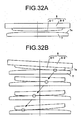
- Figs. 32A and 32B are diagrams illustrating an example combination of the creasing blade 6-1, which is an arcuate convex blade, and the creasing channel 7a, which is a female blade including a convex edge portion.
- Fig. 32A is an elevation view.
- Fig. 32B is a diagram illustrating operations of elements of Fig. 32A .
- Figs. 33A and 33B are diagrams illustrating an example combination of the creasing blade 6-1, which is an arcuate convex blade, and the creasing channel 7a, which is a female blade including a concave edge portion.
- Fig. 33A is an elevation view.
- Fig. 33B is a diagram illustrating operations of elements of Fig. 33A .
- a radius of the arc of the receiving member 7 is preferably greater than a radius of the arc of the creasing blade 6-1. More specifically, an absolute value of a curvature of the creasing blade 6-1 is greater than an absolute value of a curvature of the creasing channel 7a.
- the curvatures of the creasing blade 6-1 and the creasing channel 7a are of opposite sign.
- Fig. 34 is a diagram illustrating operations in a situation where a crease is produced with a plurality of creasing strokes by using the combination illustrated in Figs. 31A and 31B .
- a contact point is indicated by a hollow circle.
- a crease is produced with a plurality of creasing strokes, pivoting motion of the creasing blade 6-1 during creasing causes the hollow circle representing the contact position to reciprocate. Producing a crease with a plurality of creasing strokes in this manner allows smooth creasing, causing a decrease in productivity less likely to occur than that by using parallel blades.
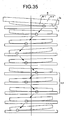
- Fig. 35 also illustrates an example where a crease is produced with a plurality of creasing strokes as with the example discussed above.
- the creasing blade 6-1 which is arcuate, makes a point-to-point contact with the creasing channel 7a. Accordingly, a desired portion of a crease can be creased sharply.
- an area, indicated by L1 where a hollow circle moves is creased sharply.
- Fig. 36 illustrates an example where areas, which are two end portions and indicated by L2 and L3, where a hollow circle moves are creased sharply.
- Fig. 37 illustrates an example where an area, which is a desired area near a center portion and indicated by L4, where a hollow circle moves is creased sharply.
- the areas indicated by L3, L3, and L4 are each creased more frequently than the other areas are.
- a creasing-blade contact duration is set to any one of t1, t2, and t3, and a creasing-stroke count is preferably set to any one of u1, u2, and u3 depending on results of determinations related to r1, which is a predetermined sheet thickness, s1, which is a predetermined sheet size, and whether the sheet is special paper.
- the creasing-blade contact durations t1, t2, and t3 and the creasing-stroke counts u1, u2, and u3 are to be determined in advance. For a sheet to be creased with a plurality of creasing strokes, it is preferable that determination as to whether additional creasing position is a center portion of the sheet or two end portions of the sheet can be made.
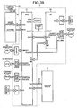
- Fig. 38 is a block diagram illustrating a control structure of the image forming system including the creasing device A, the folding device B that performs folding, and the image forming apparatus E.
- the creasing device A includes a control circuit equipped with a microcomputer including a central processing unit (CPU) A1 and an input/output (I/O) interface A2.
- CPU central processing unit
- I/O input/output
- Various signals are fed to the CPU A1 via a communications interface A3 from the CPU, various switches on a control panel E1, and various sensors (not shown) of the image forming apparatus E.
- the CPU A1 performs predetermined control operations based on a thus-fed signal.
- the CPU A1 receives signals similar to those mentioned above from the folding device B via a communications interface A4 and performs predetermined control operations based on a thus-fed signal.
- the CPU A1 also performs drive control for solenoids and motors via drivers and motor drivers and obtains detection information from sensors in the device via the interface.
- the CPU A1 also performs drive control for motors via the I/O interface A2 and via motor drivers according to an entity to be controlled and sensors and obtains detection information from sensors.
- the CPU A1 performs the control operations discussed above by reading program codes stored in read only memory (ROM) (not shown), storing the program codes into random access memory (RAM) (not shown), and executing program instructions defined in the program codes by using the RAM as a working area and data buffer.
- ROM read only memory
- RAM random access memory
- the creasing device A illustrated in Fig. 38 is controlled according to an instruction or information fed from the CPU of the image forming apparatus E.
- An operating instruction is input by a user from the control panel E1 of the image forming apparatus E.
- the image forming apparatus E and the control panel E1 are connected to each other via a communications interface E2. Accordingly, an operation signal input from the control panel E1 is transmitted from the image forming apparatus E to the creasing device A and to the folding device B. Operation status and functions of the devices A and B are indicated on the control panel E1 for a user.
- Fig. 39 is a flowchart for operations to be performed by the CPU A1 of the creasing device A to determine a creasing-blade contact duration and a creasing-stroke count.
- each of a determination related to a thickness of a sheet (STEP S1), a determination related to a sheet size (STEP S2), a determination as to whether the sheet is special paper or ordinary paper (STEP S3), a determination related to a creasing-stroke count (STEP S4), and a determination as to whether an additional creasing position is across the sheet (STEP S5) is made.
- results of the determinations at STEP S1 to STEP S5 are all YES, or, more specifically, the thickness of the sheet is equal to or greater than r1, the sheet size is equal to or greater than s1, the sheet is special paper, the creasing-stroke count is equal to or greater than u1, and the additional creasing position is across the sheet, creasing (for instance, operations illustrated in Fig. 34 ) is performed with the creasing-blade contact duration set to t1 and the creasing-stroke count set to u1 (STEP S6).
- the additional creasing position is not across the sheet at STEP S5, whether the additional creasing position is a center portion or end portions is determined at STEP S7. If the additional creasing position is the center portion, creasing (for instance, operations illustrated in Fig. 35 ) including the additional creasing on the center portion is performed with the creasing-blade contact duration set to t1 and the creasing-stroke count set to u1 at STEP S8. If the additional creasing position is the end portions, creasing (for instance, operations illustrated in Fig. 36 ) including the additional creasing on the two end portions is performed with the creasing-blade contact duration set to t1 and the creasing-stroke count set to u1 at STEP S9.
- process control proceeds to STEP S10 where creasing is performed with the creasing-blade contact duration set to t2 and the creasing-stroke count set to u2. If it is determined that the sheet thickness is smaller than r1 at STEP S1 or if the sheet size is smaller than s1 at STEP S2, process control proceeds to STEP S11 where creasing is performed with the creasing-blade contact duration set to t3 and the creasing-stroke count set to u3.
- a creasing blade male blade
- a creasing channel female blade
- the pressure to be applied by the creasing blade should preferably be high, which results in application of a large load during creasing.
- a large load is applied, a sufficient crease cannot be produced.
- a uniform crease is not always produced because the male blade, the female blade, and a sheet to be creased are not always in perfect-parallel alignment.
- the creasing blade 6-1 has the arcuate shape; however, relative relationship stands between the shapes of the creasing blade 6-1 and the creasing channel 7a.
- the creasing channel 7a can have an arcuate shape protruding relative to the creasing blade 6-1 in inverse of the embodiment discussed above.
- one member of a first member and a second member includes an arcuate edge make a point-to-point contact with a sheet therebetween. This allows reduction in processing time and production of a uniform crease in the sheet.
Landscapes
- Physics & Mathematics (AREA)
- General Physics & Mathematics (AREA)
- Folding Of Thin Sheet-Like Materials, Special Discharging Devices, And Others (AREA)
Claims (10)
- Rillvorrichtung (A) zum blattweisen Rillen von Blättern, wobei die Rillvorrichtung (A) Folgendes umfasst:ein erstes Element (6), das sich in einer Richtung, senkrecht zu einer Blattförderrichtung, erstreckt und eine Stempelklinge (6-1) einschließt, wobei die Stempelklinge (6-1) einen konvexes Querschnitt hat und ein Kantenabschnitt der Stempelklinge eine bogenförmige Gestalt hat,ein zweites Element (7), das sich in der Richtung, senkrecht zu der Blattförderrichtung, erstreckt und eine Gesenkklinge (7a) einschließt, wobei die Gesenkklinge (7a) ermöglicht, dass die Stempelklinge (6-1) mit einem Blatt zwischen der Gesenkklinge (7a) und der Stempelklinge (6-1) an dieselbe angelegt wird,und eine Antriebseinheit (40), die dafür angeordnet ist, das erste Element (6) und das zweite Element (7) relativ in und außer Berührung miteinander zu bringen, um zu veranlassen, dass ein an einer vorbestimmten Position angehaltenes Blatt zwischen dem ersten Element (6) und dem zweiten Element (7) eingeklemmt wird,wobei die Antriebseinheit ferner dafür angeordnet ist, zu veranlassen, dass die Stempelklinge schwenkt, um dadurch mit dem Kantenabschnitt, der eine bogenförmige Gestalt hat, eine Rille in dem Blatt zu formen.
- Rillvorrichtung (A) nach Anspruch 1, wobei die bogenförmige Gestalt der Stempelklinge im Verhältnis zu einem Kantenabschnitt der Gesenkklinge (7a) vorspringt.
- Rillvorrichtung (A) nach Anspruch 1 oder 2, wobei ein Kantenabschnitt der Gesenkklinge (7a) eine lineare Gestalt hat.
- Rillvorrichtung (A) nach Anspruch 1 oder 2, wobei ein Kantenabschnitt der Gesenkklinge (7a) eine konvexe bogenförmige Gestalt hat.
- Rillvorrichtung (A) nach Anspruch 1 oder 2, wobei ein Kantenabschnitt der Gesenkklinge (7a) eine konkave bogenförmige Gestalt hat.
- Rillvorrichtung (A) nach einem der Ansprüche 1 bis 5, wobei eine Position, wo das erste Element (6) und das zweite Element (7) in Berührung miteinander kommen, außerhalb eines Bereichs liegt, wo ein beliebiges der Blätter aller anwendbaren Größen hindurchgeht.
- Rillvorrichtung (A) nach einem der Ansprüche 1 bis 6, die ferner eine Steuereinheit (A1) umfasst, wobei die Steuereinheit (A1) dafür konfiguriert ist, zu veranlassen, dass die Antriebseinheit (40) in einem Augenblick, in dem ein Kantenabschnitt des ersten Elements (6) und ein Kantenabschnitt des zweiten Elements (7) in Berührung miteinander kommen, mit einer niedrigen und nach der Berührung mit einer hohen Geschwindigkeit läuft.
- Rillvorrichtung (A) nach einem der Ansprüche 1 bis 6, die eine Steuereinheit (A1) umfasst, oder Anspruch 7, wobei
die Steuereinheit (A1) dafür konfiguriert ist, eine Berührungsdauer, über die das erste Element (6) und das zweite Element (7) in Berührung miteinander sein sollen, und eine Rillhubzahl entsprechend einer Papierart des Blattes, einer Dicke des Blattes und einer Größe des Blattes zu bestimmen, und
die Steuereinheit (A1) dafür konfiguriert ist, zu veranlassen, dass die Antriebseinheit (40) entsprechend der Berührungsdauer und der Rillhubzahl läuft. - Rillvorrichtung (A) nach einem der Ansprüche 1 bis 8, wobei, in einem Vorgang zum Erzeugen der Rille, die Antriebseinheit (40) dafür konfiguriert ist, eine Antriebsrichtung an einer gewünschten Position umzuschalten, wodurch sie zum Erzeugen eines scharf gerillten Abschnitts eine Rillhandlung mehrere Male an einem gewünschten Bereich in einem zu rillenden Bereich durchführt.
- Bilderzeugungssystem, das Folgendes umfasst:die Rillvorrichtung (A) nach einem der Ansprüche 1 bis 9 undeine Bilderzeugungsvorrichtung zum Erzeugen eines Bildes auf einem Blattelement.
Applications Claiming Priority (1)
| Application Number | Priority Date | Filing Date | Title |
|---|---|---|---|
| JP2010131103A JP2011256002A (ja) | 2010-06-08 | 2010-06-08 | 筋付け装置、及び画像形成システム |
Publications (2)
| Publication Number | Publication Date |
|---|---|
| EP2394943A1 EP2394943A1 (de) | 2011-12-14 |
| EP2394943B1 true EP2394943B1 (de) | 2015-09-16 |
Family
ID=44501802
Family Applications (1)
| Application Number | Title | Priority Date | Filing Date |
|---|---|---|---|
| EP11250544.1A Not-in-force EP2394943B1 (de) | 2010-06-08 | 2011-05-23 | Faltvorrichtung und Bilderzeugungssystem |
Country Status (3)
| Country | Link |
|---|---|
| US (1) | US8413974B2 (de) |
| EP (1) | EP2394943B1 (de) |
| JP (1) | JP2011256002A (de) |
Families Citing this family (11)
| Publication number | Priority date | Publication date | Assignee | Title |
|---|---|---|---|---|
| JP2011251816A (ja) * | 2010-06-02 | 2011-12-15 | Ricoh Co Ltd | 筋付け装置、及び画像形成システム |
| JP2012126472A (ja) | 2010-12-13 | 2012-07-05 | Ricoh Co Ltd | 筋付け装置及び画像形成システム |
| JP5625870B2 (ja) | 2010-12-16 | 2014-11-19 | 株式会社リコー | 筋付け装置及び画像形成システム |
| JP5938909B2 (ja) | 2012-01-11 | 2016-06-22 | 株式会社リコー | 用紙搬送システム、用紙搬送プログラム、及び用紙搬送方法 |
| JP6291807B2 (ja) | 2013-11-25 | 2018-03-14 | 株式会社リコー | 給紙装置および画像形成装置 |
| ITUB20161084A1 (it) * | 2016-02-26 | 2017-08-26 | K G S S R L Unipersonale | Dispositivo di cordonatura per la realizzazione di cordoni di piegatura in articoli cartotecnici e di legatoria, nonche' macchina comprendente tale dispositivo |
| US10745234B2 (en) * | 2017-06-16 | 2020-08-18 | Canon Finetech Nisca Inc. | Sheet processing apparatus, image forming system, and sheet processing method |
| JP7045651B2 (ja) * | 2018-03-19 | 2022-04-01 | 株式会社リコー | シート処理装置、画像形成装置及び画像形成システム |
| JP7593067B2 (ja) * | 2020-11-17 | 2024-12-03 | 富士フイルムビジネスイノベーション株式会社 | 綴じ部および綴じ装置 |
| JP7673420B2 (ja) * | 2021-02-18 | 2025-05-09 | 富士フイルムビジネスイノベーション株式会社 | 後処理装置及び画像形成装置 |
| US12043508B2 (en) | 2022-01-31 | 2024-07-23 | Ricoh Company, Ltd. | Medium processing apparatus and image forming system incorporating same |
Family Cites Families (15)
| Publication number | Priority date | Publication date | Assignee | Title |
|---|---|---|---|---|
| WO2000018583A1 (en) * | 1998-09-29 | 2000-04-06 | Hewlett-Packard Company | Method and apparatus for making booklets |
| JP4311810B2 (ja) * | 1999-04-26 | 2009-08-12 | ホリゾン・インターナショナル株式会社 | 中綴折機 |
| JP2002326290A (ja) * | 2001-05-07 | 2002-11-12 | Graphtec Corp | 罫線形成方法 |
| GB0122381D0 (en) | 2001-09-15 | 2001-11-07 | Morgana Systems Ltd | Creasing and folding process |
| US7416177B2 (en) | 2004-09-16 | 2008-08-26 | Ricoh Company, Ltd. | Sheet folding apparatus, sheet processing apparatus and image forming apparatus |
| JP4950566B2 (ja) * | 2005-09-12 | 2012-06-13 | 株式会社リコー | 穿孔装置、画像形成システム |
| JP4047899B1 (ja) * | 2006-11-01 | 2008-02-13 | 大脇 基弘 | 用紙の折り曲げ装置とこれが装着されたプリンタ及びコピー機 |
| US7740238B2 (en) * | 2007-03-02 | 2010-06-22 | Toshiba Tec Kabushiki Kaisha | Sheet processing apparatus |
| US7770876B2 (en) * | 2007-08-28 | 2010-08-10 | Kabushiki Kaisha Toshiba | Creasing device, post-processing apparatus equipped therewith, creasing method, image forming apparatus and crease-added printing method |
| JP4506836B2 (ja) | 2008-01-14 | 2010-07-21 | 富士ゼロックス株式会社 | 折り筋装置及びこれを用いた後処理装置並びに記録材処理装置 |
| US8061701B2 (en) * | 2008-02-08 | 2011-11-22 | Kabushiki Kaisha Toshiba | Sheet folding apparatus, image forming apparatus using the same, and sheet folding method |
| JP5285378B2 (ja) * | 2008-10-01 | 2013-09-11 | ニスカ株式会社 | シート後処理装置 |
| JP4739398B2 (ja) | 2008-12-03 | 2011-08-03 | 株式会社ノルコーポレーション | ビーズ環作成台 |
| JP2010265115A (ja) | 2009-04-13 | 2010-11-25 | Ricoh Co Ltd | 背面形成装置、中綴じ製本装置、小口裁断装置、及び画像形成装置 |
| JP4787897B2 (ja) | 2009-09-14 | 2011-10-05 | 株式会社リコー | 背面形成装置、及び画像形成システム |
-
2010
- 2010-06-08 JP JP2010131103A patent/JP2011256002A/ja active Pending
-
2011
- 2011-05-17 US US13/067,206 patent/US8413974B2/en active Active
- 2011-05-23 EP EP11250544.1A patent/EP2394943B1/de not_active Not-in-force
Also Published As
| Publication number | Publication date |
|---|---|
| JP2011256002A (ja) | 2011-12-22 |
| EP2394943A1 (de) | 2011-12-14 |
| US8413974B2 (en) | 2013-04-09 |
| US20110301008A1 (en) | 2011-12-08 |
Similar Documents
| Publication | Publication Date | Title |
|---|---|---|
| US8413974B2 (en) | Creasing device and image forming system | |
| US8528891B2 (en) | Creasing device and image forming system | |
| US8419003B2 (en) | Creasing device and image forming system | |
| US8465012B2 (en) | Creasing device and image forming system | |
| US8424859B2 (en) | Creasing apparatus and image forming system | |
| US8974360B2 (en) | Creasing device, image forming system, and creasing method | |
| US20110301005A1 (en) | Image forming system, sheet finisher, and folding method | |
| JP6197441B2 (ja) | 用紙処理装置、画像形成システム及び用紙折り方法 | |
| EP2371750B1 (de) | Faltvorrichtung und Bilderzeugungssystem | |
| EP2634125B1 (de) | Vorrichtung zum Falten eines Blattstapels | |
| EP2810905A1 (de) | Blattverarbeitungsvorrichtung, Bilderzeugungssystem und Blattförderverfahren | |
| JP2012056674A (ja) | 後処理装置 | |
| JP5904222B2 (ja) | 用紙折り装置及び画像形成装置 | |
| JP6589805B2 (ja) | シート後処理装置及びそれを備えた画像形成システム | |
| JP2010132368A (ja) | カール矯正装置および画像形成装置ならびにシート紙後処理装置 | |
| US20060049574A1 (en) | Sheet folding apparatus | |
| US8105227B2 (en) | Pressure reducing folding system | |
| JP2012056686A (ja) | 用紙折り装置、画像形成システム及び用紙増し折り方法 | |
| JP2011057423A (ja) | 折り跡付け装置、及び画像形成システム | |
| US12617649B2 (en) | Paper creasing device and printer | |
| US8444540B2 (en) | Pressure reducing folding system that adapts to booklet thickness | |
| JP5577914B2 (ja) | 筋付け装置、及び画像形成システム | |
| JP2011105466A (ja) | 折り跡付け装置、画像形成システム、及び折り跡付け方法 | |
| CN104444557A (zh) | 折纸机及其控制方法、纸张后处理装置和成册系统 | |
| JP2004168533A (ja) | 原紙の折装置及び製造方法 |
Legal Events
| Date | Code | Title | Description |
|---|---|---|---|
| 17P | Request for examination filed |
Effective date: 20110606 |
|
| AK | Designated contracting states |
Kind code of ref document: A1 Designated state(s): AL AT BE BG CH CY CZ DE DK EE ES FI FR GB GR HR HU IE IS IT LI LT LU LV MC MK MT NL NO PL PT RO RS SE SI SK SM TR |
|
| AX | Request for extension of the european patent |
Extension state: BA ME |
|
| PUAI | Public reference made under article 153(3) epc to a published international application that has entered the european phase |
Free format text: ORIGINAL CODE: 0009012 |
|
| GRAP | Despatch of communication of intention to grant a patent |
Free format text: ORIGINAL CODE: EPIDOSNIGR1 |
|
| INTG | Intention to grant announced |
Effective date: 20150415 |
|
| GRAS | Grant fee paid |
Free format text: ORIGINAL CODE: EPIDOSNIGR3 |
|
| GRAA | (expected) grant |
Free format text: ORIGINAL CODE: 0009210 |
|
| RIN1 | Information on inventor provided before grant (corrected) |
Inventor name: AIBA,GO Inventor name: OIKAWA,NAOKI Inventor name: ISHIKAWA,NAOYUKI Inventor name: HATTORI, HITOSHI Inventor name: NAGASAKO,SHUUYA Inventor name: KOJIMA,HIDETOSHI Inventor name: KIKKAWA, NAOHIRO Inventor name: SHIBASAKI, YUUSUKE Inventor name: SAITO,TAKASHI |
|
| AK | Designated contracting states |
Kind code of ref document: B1 Designated state(s): AL AT BE BG CH CY CZ DE DK EE ES FI FR GB GR HR HU IE IS IT LI LT LU LV MC MK MT NL NO PL PT RO RS SE SI SK SM TR |
|
| REG | Reference to a national code |
Ref country code: GB Ref legal event code: FG4D |
|
| REG | Reference to a national code |
Ref country code: CH Ref legal event code: EP |
|
| REG | Reference to a national code |
Ref country code: IE Ref legal event code: FG4D |
|
| REG | Reference to a national code |
Ref country code: AT Ref legal event code: REF Ref document number: 749633 Country of ref document: AT Kind code of ref document: T Effective date: 20151015 |
|
| REG | Reference to a national code |
Ref country code: DE Ref legal event code: R096 Ref document number: 602011019787 Country of ref document: DE |
|
| REG | Reference to a national code |
Ref country code: NL Ref legal event code: MP Effective date: 20150916 |
|
| PG25 | Lapsed in a contracting state [announced via postgrant information from national office to epo] |
Ref country code: FI Free format text: LAPSE BECAUSE OF FAILURE TO SUBMIT A TRANSLATION OF THE DESCRIPTION OR TO PAY THE FEE WITHIN THE PRESCRIBED TIME-LIMIT Effective date: 20150916 Ref country code: GR Free format text: LAPSE BECAUSE OF FAILURE TO SUBMIT A TRANSLATION OF THE DESCRIPTION OR TO PAY THE FEE WITHIN THE PRESCRIBED TIME-LIMIT Effective date: 20151217 Ref country code: LT Free format text: LAPSE BECAUSE OF FAILURE TO SUBMIT A TRANSLATION OF THE DESCRIPTION OR TO PAY THE FEE WITHIN THE PRESCRIBED TIME-LIMIT Effective date: 20150916 Ref country code: LV Free format text: LAPSE BECAUSE OF FAILURE TO SUBMIT A TRANSLATION OF THE DESCRIPTION OR TO PAY THE FEE WITHIN THE PRESCRIBED TIME-LIMIT Effective date: 20150916 Ref country code: NO Free format text: LAPSE BECAUSE OF FAILURE TO SUBMIT A TRANSLATION OF THE DESCRIPTION OR TO PAY THE FEE WITHIN THE PRESCRIBED TIME-LIMIT Effective date: 20151216 |
|
| REG | Reference to a national code |
Ref country code: LT Ref legal event code: MG4D |
|
| REG | Reference to a national code |
Ref country code: AT Ref legal event code: MK05 Ref document number: 749633 Country of ref document: AT Kind code of ref document: T Effective date: 20150916 |
|
| PG25 | Lapsed in a contracting state [announced via postgrant information from national office to epo] |
Ref country code: SE Free format text: LAPSE BECAUSE OF FAILURE TO SUBMIT A TRANSLATION OF THE DESCRIPTION OR TO PAY THE FEE WITHIN THE PRESCRIBED TIME-LIMIT Effective date: 20150916 Ref country code: HR Free format text: LAPSE BECAUSE OF FAILURE TO SUBMIT A TRANSLATION OF THE DESCRIPTION OR TO PAY THE FEE WITHIN THE PRESCRIBED TIME-LIMIT Effective date: 20150916 Ref country code: RS Free format text: LAPSE BECAUSE OF FAILURE TO SUBMIT A TRANSLATION OF THE DESCRIPTION OR TO PAY THE FEE WITHIN THE PRESCRIBED TIME-LIMIT Effective date: 20150916 |
|
| PG25 | Lapsed in a contracting state [announced via postgrant information from national office to epo] |
Ref country code: NL Free format text: LAPSE BECAUSE OF FAILURE TO SUBMIT A TRANSLATION OF THE DESCRIPTION OR TO PAY THE FEE WITHIN THE PRESCRIBED TIME-LIMIT Effective date: 20150916 |
|
| PG25 | Lapsed in a contracting state [announced via postgrant information from national office to epo] |
Ref country code: IS Free format text: LAPSE BECAUSE OF FAILURE TO SUBMIT A TRANSLATION OF THE DESCRIPTION OR TO PAY THE FEE WITHIN THE PRESCRIBED TIME-LIMIT Effective date: 20160116 Ref country code: IT Free format text: LAPSE BECAUSE OF FAILURE TO SUBMIT A TRANSLATION OF THE DESCRIPTION OR TO PAY THE FEE WITHIN THE PRESCRIBED TIME-LIMIT Effective date: 20150916 Ref country code: EE Free format text: LAPSE BECAUSE OF FAILURE TO SUBMIT A TRANSLATION OF THE DESCRIPTION OR TO PAY THE FEE WITHIN THE PRESCRIBED TIME-LIMIT Effective date: 20150916 Ref country code: ES Free format text: LAPSE BECAUSE OF FAILURE TO SUBMIT A TRANSLATION OF THE DESCRIPTION OR TO PAY THE FEE WITHIN THE PRESCRIBED TIME-LIMIT Effective date: 20150916 Ref country code: CZ Free format text: LAPSE BECAUSE OF FAILURE TO SUBMIT A TRANSLATION OF THE DESCRIPTION OR TO PAY THE FEE WITHIN THE PRESCRIBED TIME-LIMIT Effective date: 20150916 Ref country code: SK Free format text: LAPSE BECAUSE OF FAILURE TO SUBMIT A TRANSLATION OF THE DESCRIPTION OR TO PAY THE FEE WITHIN THE PRESCRIBED TIME-LIMIT Effective date: 20150916 |
|
| REG | Reference to a national code |
Ref country code: FR Ref legal event code: PLFP Year of fee payment: 6 |
|
| PG25 | Lapsed in a contracting state [announced via postgrant information from national office to epo] |
Ref country code: RO Free format text: LAPSE BECAUSE OF FAILURE TO SUBMIT A TRANSLATION OF THE DESCRIPTION OR TO PAY THE FEE WITHIN THE PRESCRIBED TIME-LIMIT Effective date: 20150916 Ref country code: PL Free format text: LAPSE BECAUSE OF FAILURE TO SUBMIT A TRANSLATION OF THE DESCRIPTION OR TO PAY THE FEE WITHIN THE PRESCRIBED TIME-LIMIT Effective date: 20150916 Ref country code: AT Free format text: LAPSE BECAUSE OF FAILURE TO SUBMIT A TRANSLATION OF THE DESCRIPTION OR TO PAY THE FEE WITHIN THE PRESCRIBED TIME-LIMIT Effective date: 20150916 Ref country code: PT Free format text: LAPSE BECAUSE OF FAILURE TO SUBMIT A TRANSLATION OF THE DESCRIPTION OR TO PAY THE FEE WITHIN THE PRESCRIBED TIME-LIMIT Effective date: 20160118 |
|
| REG | Reference to a national code |
Ref country code: DE Ref legal event code: R097 Ref document number: 602011019787 Country of ref document: DE |
|
| PLBE | No opposition filed within time limit |
Free format text: ORIGINAL CODE: 0009261 |
|
| STAA | Information on the status of an ep patent application or granted ep patent |
Free format text: STATUS: NO OPPOSITION FILED WITHIN TIME LIMIT |
|
| 26N | No opposition filed |
Effective date: 20160617 |
|
| PG25 | Lapsed in a contracting state [announced via postgrant information from national office to epo] |
Ref country code: BE Free format text: LAPSE BECAUSE OF NON-PAYMENT OF DUE FEES Effective date: 20160531 Ref country code: DK Free format text: LAPSE BECAUSE OF FAILURE TO SUBMIT A TRANSLATION OF THE DESCRIPTION OR TO PAY THE FEE WITHIN THE PRESCRIBED TIME-LIMIT Effective date: 20150916 |
|
| PG25 | Lapsed in a contracting state [announced via postgrant information from national office to epo] |
Ref country code: SI Free format text: LAPSE BECAUSE OF FAILURE TO SUBMIT A TRANSLATION OF THE DESCRIPTION OR TO PAY THE FEE WITHIN THE PRESCRIBED TIME-LIMIT Effective date: 20150916 |
|
| REG | Reference to a national code |
Ref country code: DE Ref legal event code: R119 Ref document number: 602011019787 Country of ref document: DE |
|
| PG25 | Lapsed in a contracting state [announced via postgrant information from national office to epo] |
Ref country code: BE Free format text: LAPSE BECAUSE OF FAILURE TO SUBMIT A TRANSLATION OF THE DESCRIPTION OR TO PAY THE FEE WITHIN THE PRESCRIBED TIME-LIMIT Effective date: 20150916 Ref country code: LU Free format text: LAPSE BECAUSE OF FAILURE TO SUBMIT A TRANSLATION OF THE DESCRIPTION OR TO PAY THE FEE WITHIN THE PRESCRIBED TIME-LIMIT Effective date: 20160523 |
|
| REG | Reference to a national code |
Ref country code: CH Ref legal event code: PL |
|
| PG25 | Lapsed in a contracting state [announced via postgrant information from national office to epo] |
Ref country code: LI Free format text: LAPSE BECAUSE OF NON-PAYMENT OF DUE FEES Effective date: 20160531 Ref country code: CH Free format text: LAPSE BECAUSE OF NON-PAYMENT OF DUE FEES Effective date: 20160531 |
|
| REG | Reference to a national code |
Ref country code: IE Ref legal event code: MM4A |
|
| PG25 | Lapsed in a contracting state [announced via postgrant information from national office to epo] |
Ref country code: DE Free format text: LAPSE BECAUSE OF NON-PAYMENT OF DUE FEES Effective date: 20161201 |
|
| REG | Reference to a national code |
Ref country code: FR Ref legal event code: PLFP Year of fee payment: 7 |
|
| PG25 | Lapsed in a contracting state [announced via postgrant information from national office to epo] |
Ref country code: IE Free format text: LAPSE BECAUSE OF NON-PAYMENT OF DUE FEES Effective date: 20160523 |
|
| REG | Reference to a national code |
Ref country code: FR Ref legal event code: PLFP Year of fee payment: 8 |
|
| PG25 | Lapsed in a contracting state [announced via postgrant information from national office to epo] |
Ref country code: CY Free format text: LAPSE BECAUSE OF FAILURE TO SUBMIT A TRANSLATION OF THE DESCRIPTION OR TO PAY THE FEE WITHIN THE PRESCRIBED TIME-LIMIT Effective date: 20150916 Ref country code: SM Free format text: LAPSE BECAUSE OF FAILURE TO SUBMIT A TRANSLATION OF THE DESCRIPTION OR TO PAY THE FEE WITHIN THE PRESCRIBED TIME-LIMIT Effective date: 20150916 Ref country code: HU Free format text: LAPSE BECAUSE OF FAILURE TO SUBMIT A TRANSLATION OF THE DESCRIPTION OR TO PAY THE FEE WITHIN THE PRESCRIBED TIME-LIMIT; INVALID AB INITIO Effective date: 20110523 |
|
| PG25 | Lapsed in a contracting state [announced via postgrant information from national office to epo] |
Ref country code: MC Free format text: LAPSE BECAUSE OF FAILURE TO SUBMIT A TRANSLATION OF THE DESCRIPTION OR TO PAY THE FEE WITHIN THE PRESCRIBED TIME-LIMIT Effective date: 20150916 Ref country code: TR Free format text: LAPSE BECAUSE OF FAILURE TO SUBMIT A TRANSLATION OF THE DESCRIPTION OR TO PAY THE FEE WITHIN THE PRESCRIBED TIME-LIMIT Effective date: 20150916 Ref country code: MT Free format text: LAPSE BECAUSE OF NON-PAYMENT OF DUE FEES Effective date: 20160531 Ref country code: MK Free format text: LAPSE BECAUSE OF FAILURE TO SUBMIT A TRANSLATION OF THE DESCRIPTION OR TO PAY THE FEE WITHIN THE PRESCRIBED TIME-LIMIT Effective date: 20150916 |
|
| PG25 | Lapsed in a contracting state [announced via postgrant information from national office to epo] |
Ref country code: BG Free format text: LAPSE BECAUSE OF FAILURE TO SUBMIT A TRANSLATION OF THE DESCRIPTION OR TO PAY THE FEE WITHIN THE PRESCRIBED TIME-LIMIT Effective date: 20150916 |
|
| PG25 | Lapsed in a contracting state [announced via postgrant information from national office to epo] |
Ref country code: AL Free format text: LAPSE BECAUSE OF FAILURE TO SUBMIT A TRANSLATION OF THE DESCRIPTION OR TO PAY THE FEE WITHIN THE PRESCRIBED TIME-LIMIT Effective date: 20150916 |
|
| P01 | Opt-out of the competence of the unified patent court (upc) registered |
Effective date: 20230522 |
|
| PGFP | Annual fee paid to national office [announced via postgrant information from national office to epo] |
Ref country code: GB Payment date: 20240521 Year of fee payment: 14 |
|
| PGFP | Annual fee paid to national office [announced via postgrant information from national office to epo] |
Ref country code: FR Payment date: 20240529 Year of fee payment: 14 |
|
| GBPC | Gb: european patent ceased through non-payment of renewal fee |
Effective date: 20250523 |
|
| PG25 | Lapsed in a contracting state [announced via postgrant information from national office to epo] |
Ref country code: GB Free format text: LAPSE BECAUSE OF NON-PAYMENT OF DUE FEES Effective date: 20250523 |
|
| PG25 | Lapsed in a contracting state [announced via postgrant information from national office to epo] |
Ref country code: FR Free format text: LAPSE BECAUSE OF NON-PAYMENT OF DUE FEES Effective date: 20250531 |