EP2371750B1 - Faltvorrichtung und Bilderzeugungssystem - Google Patents
Faltvorrichtung und Bilderzeugungssystem Download PDFInfo
- Publication number
- EP2371750B1 EP2371750B1 EP11250397.4A EP11250397A EP2371750B1 EP 2371750 B1 EP2371750 B1 EP 2371750B1 EP 11250397 A EP11250397 A EP 11250397A EP 2371750 B1 EP2371750 B1 EP 2371750B1
- Authority
- EP
- European Patent Office
- Prior art keywords
- sheet
- folding
- creasing
- fold
- unit
- Prior art date
- Legal status (The legal status is an assumption and is not a legal conclusion. Google has not performed a legal analysis and makes no representation as to the accuracy of the status listed.)
- Not-in-force
Links
- 238000001514 detection method Methods 0.000 claims description 50
- 238000004891 communication Methods 0.000 claims description 6
- 238000010586 diagram Methods 0.000 description 37
- 238000000034 method Methods 0.000 description 22
- 230000008569 process Effects 0.000 description 14
- 238000011144 upstream manufacturing Methods 0.000 description 8
- 238000004519 manufacturing process Methods 0.000 description 2
- 238000003825 pressing Methods 0.000 description 2
- 238000007639 printing Methods 0.000 description 2
- 230000001960 triggered effect Effects 0.000 description 2
- 230000015556 catabolic process Effects 0.000 description 1
- 238000006731 degradation reaction Methods 0.000 description 1
- 238000005516 engineering process Methods 0.000 description 1
- 230000006870 function Effects 0.000 description 1
- 230000007246 mechanism Effects 0.000 description 1
- 230000009467 reduction Effects 0.000 description 1
Images









Classifications
-
- B—PERFORMING OPERATIONS; TRANSPORTING
- B65—CONVEYING; PACKING; STORING; HANDLING THIN OR FILAMENTARY MATERIAL
- B65H—HANDLING THIN OR FILAMENTARY MATERIAL, e.g. SHEETS, WEBS, CABLES
- B65H45/00—Folding thin material
- B65H45/12—Folding articles or webs with application of pressure to define or form crease lines
- B65H45/30—Folding in combination with creasing, smoothing or application of adhesive
-
- B—PERFORMING OPERATIONS; TRANSPORTING
- B65—CONVEYING; PACKING; STORING; HANDLING THIN OR FILAMENTARY MATERIAL
- B65H—HANDLING THIN OR FILAMENTARY MATERIAL, e.g. SHEETS, WEBS, CABLES
- B65H45/00—Folding thin material
- B65H45/12—Folding articles or webs with application of pressure to define or form crease lines
- B65H45/18—Oscillating or reciprocating blade folders
-
- B—PERFORMING OPERATIONS; TRANSPORTING
- B65—CONVEYING; PACKING; STORING; HANDLING THIN OR FILAMENTARY MATERIAL
- B65H—HANDLING THIN OR FILAMENTARY MATERIAL, e.g. SHEETS, WEBS, CABLES
- B65H2701/00—Handled material; Storage means
- B65H2701/10—Handled articles or webs
- B65H2701/13—Parts concerned of the handled material
- B65H2701/131—Edges
- B65H2701/1311—Edges leading edge
-
- B—PERFORMING OPERATIONS; TRANSPORTING
- B65—CONVEYING; PACKING; STORING; HANDLING THIN OR FILAMENTARY MATERIAL
- B65H—HANDLING THIN OR FILAMENTARY MATERIAL, e.g. SHEETS, WEBS, CABLES
- B65H2701/00—Handled material; Storage means
- B65H2701/10—Handled articles or webs
- B65H2701/13—Parts concerned of the handled material
- B65H2701/131—Edges
- B65H2701/1313—Edges trailing edge
-
- B—PERFORMING OPERATIONS; TRANSPORTING
- B65—CONVEYING; PACKING; STORING; HANDLING THIN OR FILAMENTARY MATERIAL
- B65H—HANDLING THIN OR FILAMENTARY MATERIAL, e.g. SHEETS, WEBS, CABLES
- B65H2801/00—Application field
- B65H2801/24—Post -processing devices
- B65H2801/27—Devices located downstream of office-type machines
Definitions
- the present invention relates to a creasing device and to an image forming system.
- the saddle-stitched booklet production is performed by saddle stitching a sheet batch, in which a plurality of sheets delivered from an image forming apparatus is bundled together, and folding the thus-saddle-stitched sheet batch in the middle of the sheet batch.
- Folding such a sheet batch containing a plurality of sheets can cause outer sheets of the sheet batch to be stretched at a folded portion by an amount greater than inner sheets. Image portions at the folded portion on outer sheets can thus be stretched, thereby causing damage, such as come off of toner, to the image portions in some cases.
- a similar phenomenon can occur when other folding treatment, such as z-fold or tri-fold, is performed.
- a sheet batch can be folded insufficiently depending on the thickness of the sheet batch.
- Creasing (scoring) devices that, to prevent come off of toner, creases at folded portion of a sheet batch prior to a folding treatment where the sheet batch undergoes single fold or the like so that even outer sheets is liable to be folded have already been known.
- Known examples of devices of this type include a device disclosed in Japanese Patent Application Laid-open No. S60-262771 .
- This known example device includes a conveying belt that conveys sheets, a pressing member that uplift a sheet-conveying surface of the conveying belt, and a V-belt that rotates in pressure contact with a sheet on the conveying belt uplifted by the pressing member and forms a crease (fold stripe) in advance in sheets, which are to be saddle stitched, for quality enhancement of saddle stitching.
- Known creasing devices are configured such that a sheet detection reference position for determining a crease position, and a sheet detection reference position for a unit that performs folding treatment in a subsequent process differ from each other. More specifically, for instance, a sheet is creased at a predetermined position with reference to a front edge of a sheet, the sheet is folded at a predetermined position with reference to a rear edge of the sheet in a folding treatment of a subsequent process. Meanwhile, even sheets of a same size can be dimensionally varied because of allowance or the like. Accordingly, such a configuration as discussed above can cause an offset between the crease position and the fold position, resulting in degradation of folding quality.
- the known technique discussed above allows a crease to be formed in sheets, which are to be saddle stitched, on a fold stripe in advance; however, the technique gives no consideration to the offset, as discussed above, where a sheet detection reference position for determining a crease position, and a sheet detection reference position for a unit that performs folding in a subsequent process differ from each other.
- a creasing device (A) including: a creasing unit that creases sheets on a one-by-one basis, which is conveyed to a folding device (B) of a subsequent stage; a sheet detection unit (SN1, SN2, SN3) that detects a position of a sheet delivered to the creasing device (A); and a control unit (111) that obtains reference information of a fold-position for the folding device (B) and performs control of a stop position of the sheet according to reference information of the fold position, thereby adjusting a crease position.
- a creasing device including: a creasing unit that creases sheets on a one-by-one basis, which is conveyed to a folding device (B) of a subsequent stage; a sheet detection unit (SN1, SN2, SN3) that detects a position of a sheet delivered to the creasing device (A); and a control unit (111) that obtains reference information of a fold-position for the folding device (B) and perform
- an image forming system including: the creasing device (A) according to claim 1 and an image forming apparatus for forming an image on a sheet member.
- the present invention relates to a creasing device that saddle-stitches a batch of sheet members (hereinafter, "sheets") delivered from a preceding stage and creases the sheets prior to folding the sheets in the middle of the sheets and to an image forming system including the creasing device and an image forming apparatus.
- sheets sheet members
- the present invention has been conceived to prevent occurrence of offset between a crease position and a fold position even when sheets are dimensionally varied. This can be attained by performing detection of sheet position for creasing relative to a sheet position reference for a folding process, which is a subsequent process, and creasing a sheet based on the detected sheet reference position. For instance, if a fold position is determined by reference to a front edge of a sheet, by determining a crease position also by reference to the front edge of the sheet, offset between a fold position and a crease position can be prevented. Hence, even when sheets are dimensionally varied, offset between a crease and a fold position that can result from the variance can be prevented.
- an example of the creasing means is a creasing unit C; examples of the folding device are a folding device B and a folding device Br; an example of the creasing device is a creasing device A; examples of the sheet sensing unit are first to third sheet sensors SN1, SN2, and SN3; an example of the control unit is a central processing unit (CPU) 111; an example of the storing unit is random access memory (RAM) (not shown); an example of the table is given in Fig. 30 ; an example of the image forming apparatus is an image forming apparatus E.
- CPU central processing unit
- RAM random access memory
- Fig. 1 is a schematic diagram illustrating a system configuration of an image forming system according to implementation of a first example of an embodiment of the present invention.
- the image forming system according to the first example includes a creasing device A, a folding device B that performs folding treatment, and an image forming apparatus E that forms a visible image on a sheet.
- the creasing device A includes first to fourth pairs of conveying rollers 1, 2, 3, and 4, an abutment plate 10, and a creasing unit C.
- the creasing unit C includes a creasing blade 11 (convex blade or creasing blade) and a receiving member 12 (creasing channel or concave channel). Creasing is performed by pinching a sheet between the creasing blade 11 and the receiving member 12 to form a crease, or a fold line, in the sheet.
- the creasing blade 11 includes a convex blade portion extending in a direction orthogonal to a sheet conveying direction, a cam 13 that moves the convex blade portion up and down, and a drive mechanism (not shown).
- the convex blade portion includes a blade that is V-shaped in cross section and edged at its tip and a base 15 to be driven by the cam 13.
- the receiving member 12 includes a channel portion that is V-shaped in cross section to conform to the shape of the blade. When a sheet is pinched between the blade portion and the channel portion, a fold line is formed in the sheet. The creased sheet is delivered to the folding device B downstream.
- the folding device B includes fifth, sixth, and seventh pairs of conveying rollers 5, 6, and 7 and a folding unit D.
- the folding unit D includes a folding tray 22, a reference fence 23, a pair of folding rollers 21, a folding plate 20, and a stacking tray 24.
- the folding tray 22 receives a sheet P1 from the seventh conveying rollers 7 positioned on the side of an upper end of the folding tray 22 and carries the sheet with a front edge of the sheet abutting on the reference fence 23.
- the pair of folding rollers 21 and the folding plate 20 are arranged facing each other with the folding tray 22 therebetween.
- the folding plate 20 is arranged on the same side as inside of a folded sheet whereas the pair of folding rollers 21 is positioned on the same side as outside of the folded sheet.
- the stacking tray 24 is located downstream in the sheet conveying direction from the pair of folding rollers 21 to receive a folded sheet or a folded sheet batch to be stacked thereon.
- the image forming apparatus E forms an image pertaining to image data fed from a scanner, a personal computer (PC), or the like on a sheet as a visible image.
- the image forming apparatus E performs image forming by using a known print engine for electrophotographic printing, droplet ejection printing, or the like.
- a CPU of a control device of the image forming apparatus E, that of the creasing device A, and that of the folding device B are in-line connected via interfaces; instructions fed from the image forming apparatus E are transmitted to the creasing device A and to the folding device B via the creasing device A; detection information, processing information, and the like are transmitted from the folding device B to the image forming apparatus E via the creasing device A; processing information is transmitted from the creasing device A to the image forming apparatus E; overall control of the image forming system is performed by the CPU of the image forming apparatus E.
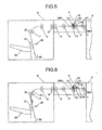
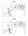
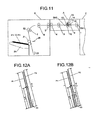
- Figs. 2 to 12 are schematic diagrams for illustrating a series of operations from creasing (scoring) to folding.
- the sheet P1 delivered from the image forming apparatus E passes by an entrance sensor (first sheet detection sensor) SN1.
- the first to the fourth pairs of conveying rollers 1, 2, 3, and 4 are triggered by detection information output from the entrance sensor SN1.
- the sheet P1 is conveyed by the first and the second pairs of conveying rollers 1 and 2 and brought into contact with the abutment plate 10 once, to thus be subject to skew correction.
- the abutment plate 10 descends in a direction indicated by an arrow in Fig. 4 .
- the sheet P1 is further conveyed.
- a second sheet detection sensor SN2 senses a front edge of the sheet P1
- the second sheet detection sensor SN2 outputs a detection signal.
- the sheet P1 is then conveyed by a predetermined distance with reference to the detection signal.
- a pressure spring 14 When a center of the sheet P1 comes to a position provided with the creasing blade 11, the driving cam 13 rotates, causing the creasing blade 11 to descend.
- the sheet P1 is subjected to pressure by a pressure spring 14, thereby being creased between the creasing blade 11 and the receiving member 12.
- the creased sheet P1 is conveyed to the folding device B by the third and the fourth folding rollers 3 and 4 and conveyed by the fifth, the sixth, and the seventh folding rollers 5, 6, and 7 to the folding unit D in the folding device B.
- succeeding sheets P2, P3 and Pn are also creased by the creasing blade 11 and conveyed to the folding device B in a similar manner.
- a batch of sheets P1 to Pn stacked on the folding unit is held by the reference fence and conveyed until a creased portion of the batch of sheets P1 to Pn reaches a position provided with the folding unit.
- the folding plate 20 moves in a direction (toward a nip between the pair of folding rollers) indicated by an arrow to press the batch of sheets P1 to Pn into the nip between the pair of folding rollers 21, causing the pair of folding rollers 21 to perform folding treatment.
- the batch of folded sheets P1 to Pn is sequentially stacked on the stacking tray 24 as illustrated in Fig. 11 .
- the series of operations from creasing to folding is performed in this manner.
- the creasing unit C adapts to a fold style, such as Z-fold, by producing creases corresponding to the number of times folding to be performed.
- the reference position for creasing position is the front edge of the sheet as illustrated in Fig. 4 .
- the sheet is moved to a folding position where the sheet is folded. Accordingly, a fold position is also determined by reference to the front edge of the sheet.
- the length of the first sheet P1 in the conveying direction is L
- the length of the second sheet P2 in the conveying direction is L+ ⁇
- the sheets are folded at a position of U2 from the front edge of the first sheet P1
- the sheets are creased at the position of U2 from the front edge of the first sheet P1 and folded at the position because the reference fence 23 serves as the front edge reference for fold position.
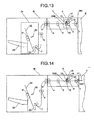
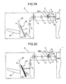
- Fig. 13 is a schematic diagram illustrating a system configuration of an image forming system, in which a fold position for the folding unit is determined by reference to a rear edge of a sheet.
- the image forming system includes the creasing device A, a folding device Br that performs folding treatment, and the image forming apparatus E. Elements similar to those illustrated in Figs. 1 to 11 are denoted by like reference numerals and symbols, and repeated descriptions are omitted.
- This system differs from the system illustrated in Fig. 1 in the configuration of a folding unit Dr of the folding device Br.
- the folding unit Dr is constructed such that the seventh conveying rollers 7 are positioned on the side of a lower end of the folding tray 22 to deliver a sheet from the side of the lower end; the delivered sheet at a rear edge is brought into contact against the reference fence 23 provided at a lower end of the folding tray 22 that serves as a reference for the rear edge of the sheet.
- the folding tray 22 carries the sheet with the rear edge of the sheet abutting on the reference fence 23. Accordingly, although the situation in Fig. 1 and the situation in Fig.
- the reference fence 23 illustrated in Fig. 1 serves as a front-edge reference whereas the reference fence 23 illustrated in Fig. 13 serves as a rear-edge reference.
- the sheet P1 delivered from the image forming apparatus E passes by the entrance sensor SN1.
- the first to the fourth conveying rollers 1, 2, 3, and 4 are triggered by detection information output from the entrance sensor SN1.
- the sheet P1 is conveyed by the first and the second conveying rollers 1 and 2 and brought into contact with the abutment plate 10 once and is subject to skew correction. After completion of the skew correction, the abutment plate 10 descends in a direction indicated by an arrow in Fig. 16 .
- the sheet P1 is further conveyed.
- the creasing device A determines controlling crease position based on either the front edge of the sheet or the rear edge of the sheet based on reference information of fold-position for the folding treatment for the subsequent process.
- the folding device Br is configured to determine a fold position by reference to a rear edge of a sheet; accordingly, the creasing device A also performs controlling the crease position by reference to the rear edge of the sheet.
- the second sheet detection sensor SN2 detects a position of the rear edge of the sheet.
- the sheet P1 is conveyed upstream by a predetermined distance based on a detection signal output from the second sheet detection sensor SN2.
- the drive cam 13 is rotated, causing the creasing blade 11 to descend.
- the sheet P1 is subjected to pressure by the pressure spring 14, thereby being creased. Subsequently, as illustrated in Fig.
- the creased sheet P1 is conveyed to the folding device Br by the third and the fourth folding rollers 3 and 4 and then conveyed to the folding unit Dr by the fifth, the sixth, and the seventh folding rollers 5, 6, and 7 in the folding device Br.
- the subsequent sheet P2 to Pn are also creased by the creasing blade 11 and conveyed to the folding unit Dr in a similar manner.
- the batch of stacked sheets P1 to Pn on the folding tray 22 is uplifted until the creased portion of the batch of sheets P1 to Pn supported by the rear-end fence 23 reaches a position provided with the folding plate 20.
- the folding plate 20 moves in a direction indicated by an arrow and forces the batch of sheets P1 to Pn into the nip between the pair of folding rollers 21 to perform folding treatment.
- the batch of folded sheets P1 to Pn is delivered to and stacked on the stacking tray 24 as illustrated in Fig. 23 .
- Fig. 24 is a block diagram illustrating control structure of the image forming system including the creasing device A, the folding device B or Br that performs folding treatment, and the image forming apparatus E.
- the creasing device A includes a control circuit equipped with a microcomputer including a CPU 111 and an input/output (I/O) interface 112. Signals are fed to the CPU 111 from the CPU, various switches on a control panel, and various sensors (not shown) of the image forming apparatus E via a communications interface 110.
- the CPU 111 performs predetermined control operations based on fed signals.
- the CPU 111 receives signals similar to those mentioned above from the folding device B or Br via a communication interface 113 and performs predetermined control operations based on fed signals.
- the CPU 111 also performs drive control for solenoids and motors via drivers and motor drivers and obtains sensor information in the device via the interface.
- the CPU 111 also performs drive control for motors via the I/O interface 112 and via motor drivers according to an entity to be controlled and sensors and obtains sensor information from sensors. Control operations discussed above are performed by reading program codes stored in read only memory (ROM) (not shown) and executing program instructions defined in the program codes while using RAM (not shown) as a working area and data buffer.
- ROM read only memory
- Fig. 25 is a flowchart illustrating a series of procedure of operations from creasing to folding performed by the CPU 111 of the creasing device A.
- the CPU 111 of the creasing device A obtains reference information of the fold-position for the folding device B (Step S102).
- the CPU 111 obtains reference information of the fold-position from the image forming apparatus E or the folding device B via the communication interface 110 or 113.
- the entrance sensor SN1 detects passage of a front edge of a sheet delivered from the image forming apparatus E (Step S103).
- conveyance of the sheet is started by the conveying rollers 1 to 7 (Step S104).
- Step S105 whether the folding device B is front-edge or rear-edge basis is checked based on reference information of the fold-position obtained at Step S102 (Step S105).
- the sheet is conveyed from a time point where the front edge of the sheet has cut off the sheet detection sensor SN2 (YES at Step S106) by a predetermined distance (for an instance of half fold, for example, until a crease position is at a half length in the conveying direction of the sheet) and stopped at the position (Step S107).
- the creasing blade 11 is caused to descend to perform creasing (scoring treatment) of the sheet between the receiving member 12 and the creasing blade 11 (Step S110).
- the sheet is then conveyed to the folding device B (Step S111).
- Step S105 treatment is performed assuming that the folding device B is based on rear-edge, and the sheet is conveyed upstream from a time point where the sheet detection sensor SN2 has sensed a rear edge of the sheet (YES at Step S108) by a predetermined distance (in a case of half fold, for instance, until a crease position is located at a distance of a half length of the sheet in the sheet conveying direction) and stopped at the position (Step S109). Creasing treatment is performed (Step S110) and the sheet is conveyed to the folding device B (Step S111).
- the crease position is determined at Step S107 or at Step S109.
- a sheet delivered to the creasing device A is moved in a reverse direction (upstream) before the sheet undergoes creasing.
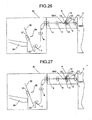
- a second example is an example adapted to a rear-edge basis without moving the sheet in the reverse direction, or upstream.
- the entrance sensor SN1 and the sheet detection sensor SN2 capable of detecting a front edge or a rear edge of a sheet.
- crease position control is performed based on an output signal of one of the different sensors according to reference information of fold-position for the folding device B.
- the creasing device A determines to control the crease position using which one of a front edge of or a rear edge of a sheet as a reference based on reference information of the fold-position for the folding process, which is the subsequent process.
- the folding device Br is configured to determine a fold position by reference to a rear edge of a sheet; accordingly, the creasing device A also control the crease position by reference to the rear edge of the sheet.
- the entrance sensor SN1 detects a position of the rear edge of the sheet.
- a crease position is determined based on a sheet detection signal output from the second sheet detection sensor SN2.
- This control allows that a process for conveying a sheet upstream can be eliminated even when the folding device is rear-edge based, which leads to reduction in sheet processing time, or, in other words, an increase in productivity.
- Fig. 28 is a flowchart illustrating a procedure of operations to be performed by the CPU 111 of the creasing device A in the second example implementation. This flowchart is similar to the flowchart of the first example illustrated in Fig. 25 but Step S108 and Step S109 are replaced with Step S108a and Step S109.
- the sheet is conveyed from a time point where the rear edge of the sheet has cut off the entrance sensor SN1 (YES at Step S108a) by a predetermined distance (in a case of half fold, for instance, until the crease position is located at a distance of a half length of the sheet in the sheet conveying direction from the rear edge of the sheet) and stopped (Step S109a). Thereafter, the sheet is creased (Step S110) and conveyed to the folding device B (Step S111).
- Fig. 29 is a schematic diagram illustrating a configuration in the third example that a plurality of sheet detection sensors that provides a reference for a crease position are arranged.
- a third sheet detection sensor SN3 is arranged between the entrance sensor SN1 and the creasing unit C in the creasing device A.
- the folding device Br is based on a rear edge of a sheet; accordingly, the creasing device A also controls crease position by reference to the rear edge of the sheet.
- the CPU 111 stores such a table as illustrated in Fig. 30 in the RAM (not shown) in the circuit control.
- This table indicates relation among sheet size information, fold positions in fold style, such as a fold position for center fold, a first fold position for Z-fold, a second fold position for Z-fold, and the first and the third sheet detection sensors SN1 and SN3 used in determination of a reference.
- the CPU 111 obtains sheet-size information and fold-style information from the image forming apparatus E or the folding device B and refers to the table of Fig. 30 to select one of an output signal from the first sheet detection sensor SN1 and an output signal from the third sheet detection sensor SN3 for use as a reference for crease position control.
- the CPU 111 detects a rear edge of a sheet based on the output signal of the selected sheet detection sensor. Referring to Fig. 31 , after the rear edge of the sheet cuts off the third sheet detection sensor SN3, the sheet is conveyed based on a rear-edge by a predetermined distance and stopped. The creasing blade 11 is driven as illustrated in Fig. 32 to crease the sheet. Thereafter, the sheet is conveyed to the folding device B where the sheet is folded as in the first example.
- this control is performed based on the sheet detection sensor, which is closer to the creasing unit C, among those. Accordingly, influence exerted by sheet slippage that can occur during sheet conveyance or the like can be lessened. As a result, accuracy of the crease position can be improved. Meanwhile, as a matter of course, if the folding device B is based on a front-edge, creasing is performed at a conveyance distance after a front edge of the sheet has cut off the second sheet detection sensor SN2.
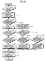
- Fig. 33 is a flowchart illustrating a procedure of operations performed by the CPU 111 of the creasing device A in the third example implementation. This flowchart is similar to the flowchart of the first example illustrated in Fig. 25 but Step S108 and Step S109 are replaced with Step S121 to Step S126.
- a sheet detection reference sensor is selected from the table in Fig. 30 based on obtained sheet-size information and fold-style information (Step S121). If the entrance sensor SN1 is selected as the reference sensor (YES at Step S122), from a starting point where the entrance sensor SN1 detected passage of the rear edge of the sheet (YES at Step S123), the sheet is conveyed by a predetermined distance from rear-edge of the sheet and stopped (Step S124). Creasing is then performed (Step S110).
- Step S110 If the entrance sensor SN1 is not selected as the reference sensor at step S122, from a starting point where the third sheet sensor SN3 detected passage of the rear edge of the sheet (YES at Step S125), the sheet is conveyed by a predetermined distance from a rear-edge of the sheet and stopped (Step S126). Creasing is then performed (Step S110).
- Step S111 the sheet is conveyed to the folding device B (Step S111) where the sheet is folded.
- a same sheet position reference as that for a folding process which is a process subsequent to creasing, can be applied to the creasing. Accordingly, occurrence of offset between a crease position and a fold position is prevented even when sheets are dimensionally varied.
Landscapes
- Folding Of Thin Sheet-Like Materials, Special Discharging Devices, And Others (AREA)
Claims (7)
- Falzvorrichtung (A), umfassend:eine Falzeinheit, die Bogen Stück für Stück falzt, worin die Bogen zu einer Faltvorrichtung (B) einer nachfolgenden Stufe zu befördern sind;eine Bogenpositionsermittlungseinheit (SN1, SN2, SN3), die eine Position eines an die Falzvorrichtung (A) übergebenen Bogens ermittelt; undeine Steuereinheit (111), die Referenzinformation einer Faltposition für die Faltvorrichtung (B) erlangt und die Steuerung einer Endposition des Bogens gemäß der Referenzinformation der Faltposition durchführt, wodurch sie eine Falzposition justiert.
- Falzvorrichtung (A) nach Anspruch 1, worin
die Falzvorrichtung eine Vielzahl von Bogenpositionsermittlungseinheiten (SN1, SN2, SN3) einschließt und
die Steuereinheit die Steuerung der Endposition des Bogens auf der Grundlage eines Ermittlungssignals durchführt, das von derjenigen Bogenpositionsermittlungseinheit (SN1, SN2, SN3) ausgegeben wird, die gemäß der Referenzinformation der Faltposition ausgewählt wird. - Falzvorrichtung (A) nach Anspruch 2, worin die Steuereinheit (111) die Steuerung der Endposition des Bogens auf der Grundlage eines Ermittlungssignals durchführt, das von derjenigen Bogenpositionsermittlungseinheit (SN1, SN2, SN3) ausgegeben wird, die gemäß der Referenzinformation von Faltposition und Bogengrößeninformation ausgewählt wird.
- Falzvorrichtung (A) nach einem der Ansprüche 1 bis 3, worin die Steuereinheit (111) bestimmt, ein von der Bogenpositionsermittlungseinheit (SN1, SN2, SN3) ausgegebenes Ermittlungssignal als eine Referenz gemäß der Referenzinformation der Faltposition, der Bogengrößeninformation und der Faltstilinformation auszuwählen.
- Falzvorrichtung (A) nach Anspruch 4, worin die Bogengrößeninformation, die Faltstilinformation und die Bogenpositionsermittlungseinheit (SN1, SN3) als Referenz vorab in einer Tabelle aufgeführt und in einer Speichereinheit gespeichert werden.
- Falzvorrichtung (A) nach einem der Ansprüche 1 bis 5, ferner umfassend:eine Kommunikationseinheit (110, 113) zum Ausführen von Kommunikation mit einer Vorrichtung, die mit der Falzvorrichtung (A) verbunden ist,worin die Steuereinheit (111) Referenzinformation der Faltposition für die Faltvorrichtung (B) über die Kommunikationseinheit (110, 113) erlangt.
- Bilderzeugungssystem, umfassend:die Falzvorrichtung (A) nach einem der Ansprüche 1 bis 6; undeine Bilderzeugungsvorrichtung zum Erzeugen eines Bildes auf einem Bogenteil.
Applications Claiming Priority (2)
| Application Number | Priority Date | Filing Date | Title |
|---|---|---|---|
| JP2010086953 | 2010-04-05 | ||
| JP2011015436A JP5636989B2 (ja) | 2010-04-05 | 2011-01-27 | 筋付け装置、及び画像形成システム |
Publications (2)
| Publication Number | Publication Date |
|---|---|
| EP2371750A1 EP2371750A1 (de) | 2011-10-05 |
| EP2371750B1 true EP2371750B1 (de) | 2013-05-08 |
Family
ID=44118361
Family Applications (1)
| Application Number | Title | Priority Date | Filing Date |
|---|---|---|---|
| EP11250397.4A Not-in-force EP2371750B1 (de) | 2010-04-05 | 2011-03-29 | Faltvorrichtung und Bilderzeugungssystem |
Country Status (3)
| Country | Link |
|---|---|
| US (1) | US8387964B2 (de) |
| EP (1) | EP2371750B1 (de) |
| JP (1) | JP5636989B2 (de) |
Families Citing this family (13)
| Publication number | Priority date | Publication date | Assignee | Title |
|---|---|---|---|---|
| JP2012126472A (ja) | 2010-12-13 | 2012-07-05 | Ricoh Co Ltd | 筋付け装置及び画像形成システム |
| JP5625870B2 (ja) | 2010-12-16 | 2014-11-19 | 株式会社リコー | 筋付け装置及び画像形成システム |
| JP5938909B2 (ja) | 2012-01-11 | 2016-06-22 | 株式会社リコー | 用紙搬送システム、用紙搬送プログラム、及び用紙搬送方法 |
| JP5870893B2 (ja) * | 2012-10-15 | 2016-03-01 | コニカミノルタ株式会社 | 用紙処理装置及び画像形成システム |
| JP6291807B2 (ja) | 2013-11-25 | 2018-03-14 | 株式会社リコー | 給紙装置および画像形成装置 |
| CN103660396B (zh) * | 2013-11-26 | 2016-08-17 | 平度市平安防盗门厂 | 一种揉纸机 |
| JP2015157457A (ja) * | 2014-02-25 | 2015-09-03 | キヤノン株式会社 | 印刷装置、印刷装置の制御方法、及びプログラム |
| JP6217690B2 (ja) * | 2015-05-20 | 2017-10-25 | コニカミノルタ株式会社 | 用紙後処理装置及び画像形成装置 |
| JP6797583B2 (ja) * | 2016-07-13 | 2020-12-09 | キヤノン株式会社 | シート処理装置及び画像形成装置 |
| US10745234B2 (en) * | 2017-06-16 | 2020-08-18 | Canon Finetech Nisca Inc. | Sheet processing apparatus, image forming system, and sheet processing method |
| JP7006117B2 (ja) * | 2017-10-16 | 2022-01-24 | 富士フイルムビジネスイノベーション株式会社 | 画像処理装置及び画像処理方法 |
| JP7524558B2 (ja) * | 2020-03-11 | 2024-07-30 | 株式会社リコー | 媒体処理装置及び画像形成システム |
| US12043508B2 (en) | 2022-01-31 | 2024-07-23 | Ricoh Company, Ltd. | Medium processing apparatus and image forming system incorporating same |
Family Cites Families (19)
| Publication number | Priority date | Publication date | Assignee | Title |
|---|---|---|---|---|
| JPS60262771A (ja) | 1984-06-06 | 1985-12-26 | Ricoh Co Ltd | 製本機能を備えた複写機における用紙折り装置 |
| JPH11322162A (ja) * | 1998-05-13 | 1999-11-24 | Canon Aptex Inc | シート処理装置及び画像形成装置 |
| JP3592138B2 (ja) * | 1999-06-28 | 2004-11-24 | 京セラミタ株式会社 | 紙折り装置 |
| JP3991891B2 (ja) * | 2003-03-13 | 2007-10-17 | コニカミノルタビジネステクノロジーズ株式会社 | シート綴じ方法およびシート後処理装置 |
| JP2007041525A (ja) * | 2005-07-08 | 2007-02-15 | Konica Minolta Business Technologies Inc | 画像形成装置、給紙装置、画像形成システム及び後処理システム |
| JP4714797B2 (ja) | 2005-09-28 | 2011-06-29 | 株式会社メイクソフトウェア | 写真シール作成装置 |
| JP4227640B2 (ja) * | 2005-11-11 | 2009-02-18 | キヤノン株式会社 | シート処理装置、これを備えた画像形成装置 |
| JP2008105316A (ja) * | 2006-10-26 | 2008-05-08 | Canon Inc | 製本装置、及び製本装置を備える画像形成装置 |
| US7975999B2 (en) * | 2007-01-31 | 2011-07-12 | Nisca Corporation | Sheet post-processing apparatus and image forming system comprising the same |
| US7740238B2 (en) * | 2007-03-02 | 2010-06-22 | Toshiba Tec Kabushiki Kaisha | Sheet processing apparatus |
| US7770876B2 (en) * | 2007-08-28 | 2010-08-10 | Kabushiki Kaisha Toshiba | Creasing device, post-processing apparatus equipped therewith, creasing method, image forming apparatus and crease-added printing method |
| JP4450053B2 (ja) * | 2007-11-13 | 2010-04-14 | 富士ゼロックス株式会社 | 記録材後処理装置および画像形成システム |
| JP4506836B2 (ja) * | 2008-01-14 | 2010-07-21 | 富士ゼロックス株式会社 | 折り筋装置及びこれを用いた後処理装置並びに記録材処理装置 |
| JP4921396B2 (ja) * | 2008-02-13 | 2012-04-25 | 株式会社リコー | シート折り装置、シート搬送装置、シート処理装置および画像形成装置 |
| JP5434386B2 (ja) | 2008-09-02 | 2014-03-05 | 東レ株式会社 | 高分子電解質膜の製造方法。 |
| JP2010265115A (ja) | 2009-04-13 | 2010-11-25 | Ricoh Co Ltd | 背面形成装置、中綴じ製本装置、小口裁断装置、及び画像形成装置 |
| JP5493922B2 (ja) | 2009-06-01 | 2014-05-14 | 株式会社リコー | 背面形成装置、用紙処理装置、及び画像形成装置 |
| JP4598151B1 (ja) | 2009-06-09 | 2010-12-15 | 株式会社リコー | 背面形成装置、シート処理装置、画像形成システム、及び背面形成方法 |
| JP4787897B2 (ja) | 2009-09-14 | 2011-10-05 | 株式会社リコー | 背面形成装置、及び画像形成システム |
-
2011
- 2011-01-27 JP JP2011015436A patent/JP5636989B2/ja not_active Expired - Fee Related
- 2011-03-29 EP EP11250397.4A patent/EP2371750B1/de not_active Not-in-force
- 2011-04-04 US US13/064,607 patent/US8387964B2/en not_active Expired - Fee Related
Also Published As
| Publication number | Publication date |
|---|---|
| US20110245055A1 (en) | 2011-10-06 |
| JP5636989B2 (ja) | 2014-12-10 |
| EP2371750A1 (de) | 2011-10-05 |
| US8387964B2 (en) | 2013-03-05 |
| JP2011230924A (ja) | 2011-11-17 |
Similar Documents
| Publication | Publication Date | Title |
|---|---|---|
| US8387964B2 (en) | Creasing device and image forming system | |
| US8413976B2 (en) | Image forming system, sheet finisher, and folding method | |
| US8613435B2 (en) | Sheet processing apparatus | |
| US8276900B2 (en) | Sheet processing apparatus and image forming apparatus equipped with the same | |
| US8844919B2 (en) | Square back processing with variable nipping | |
| JP5631172B2 (ja) | シート処理装置及び画像形成装置 | |
| JP2012056674A (ja) | 後処理装置 | |
| JP6589805B2 (ja) | シート後処理装置及びそれを備えた画像形成システム | |
| JP5230170B2 (ja) | シート搬送装置、シート処理装置及び画像形成装置 | |
| JP5647403B2 (ja) | シート給送装置及びこれを備えたシート折り装置並びに画像形成システム | |
| US7891928B2 (en) | Folded portion flattening device, post treatment apparatus and image forming apparatus | |
| JP5768528B2 (ja) | 冊子搬送装置及び画像形成システム | |
| JP5631056B2 (ja) | シート処理装置 | |
| JP4315437B2 (ja) | 紙折り装置 | |
| JP5772061B2 (ja) | 折り装置、画像形成システム、折り処理制御プログラム及び折り方法 | |
| JP5494376B2 (ja) | シート処理システム、画像形成システム及び小口断裁位置決定方法 | |
| JP4377830B2 (ja) | 紙折装置 | |
| JP6553334B2 (ja) | シート処理装置及びこれを備える画像形成装置 | |
| JP5750939B2 (ja) | シート積載装置、シート折り装置及び画像形成システム | |
| JP5217894B2 (ja) | シート折り装置及び画像形成システム | |
| JP4795261B2 (ja) | シート後処理装置および画像形成装置 | |
| JP2007098875A (ja) | 折り部平坦化装置 | |
| JP4701151B2 (ja) | 用紙折り装置、及び画像形成装置 | |
| JP2023000427A (ja) | シート折り装置、画像形成装置及び画像形成システム | |
| JP4425813B2 (ja) | 用紙後処理装置、及び画像形成システム |
Legal Events
| Date | Code | Title | Description |
|---|---|---|---|
| PUAI | Public reference made under article 153(3) epc to a published international application that has entered the european phase |
Free format text: ORIGINAL CODE: 0009012 |
|
| 17P | Request for examination filed |
Effective date: 20110405 |
|
| AK | Designated contracting states |
Kind code of ref document: A1 Designated state(s): AL AT BE BG CH CY CZ DE DK EE ES FI FR GB GR HR HU IE IS IT LI LT LU LV MC MK MT NL NO PL PT RO RS SE SI SK SM TR |
|
| AX | Request for extension of the european patent |
Extension state: BA ME |
|
| RIC1 | Information provided on ipc code assigned before grant |
Ipc: B65H 45/18 20060101ALI20120919BHEP Ipc: B65H 45/30 20060101AFI20120919BHEP |
|
| GRAP | Despatch of communication of intention to grant a patent |
Free format text: ORIGINAL CODE: EPIDOSNIGR1 |
|
| GRAS | Grant fee paid |
Free format text: ORIGINAL CODE: EPIDOSNIGR3 |
|
| GRAA | (expected) grant |
Free format text: ORIGINAL CODE: 0009210 |
|
| AK | Designated contracting states |
Kind code of ref document: B1 Designated state(s): AL AT BE BG CH CY CZ DE DK EE ES FI FR GB GR HR HU IE IS IT LI LT LU LV MC MK MT NL NO PL PT RO RS SE SI SK SM TR |
|
| REG | Reference to a national code |
Ref country code: GB Ref legal event code: FG4D |
|
| REG | Reference to a national code |
Ref country code: CH Ref legal event code: EP Ref country code: AT Ref legal event code: REF Ref document number: 610979 Country of ref document: AT Kind code of ref document: T Effective date: 20130515 |
|
| REG | Reference to a national code |
Ref country code: IE Ref legal event code: FG4D |
|
| REG | Reference to a national code |
Ref country code: DE Ref legal event code: R096 Ref document number: 602011001654 Country of ref document: DE Effective date: 20130711 |
|
| REG | Reference to a national code |
Ref country code: AT Ref legal event code: MK05 Ref document number: 610979 Country of ref document: AT Kind code of ref document: T Effective date: 20130508 |
|
| REG | Reference to a national code |
Ref country code: LT Ref legal event code: MG4D |
|
| REG | Reference to a national code |
Ref country code: NL Ref legal event code: VDEP Effective date: 20130508 |
|
| PG25 | Lapsed in a contracting state [announced via postgrant information from national office to epo] |
Ref country code: IS Free format text: LAPSE BECAUSE OF FAILURE TO SUBMIT A TRANSLATION OF THE DESCRIPTION OR TO PAY THE FEE WITHIN THE PRESCRIBED TIME-LIMIT Effective date: 20130908 Ref country code: FI Free format text: LAPSE BECAUSE OF FAILURE TO SUBMIT A TRANSLATION OF THE DESCRIPTION OR TO PAY THE FEE WITHIN THE PRESCRIBED TIME-LIMIT Effective date: 20130508 Ref country code: AT Free format text: LAPSE BECAUSE OF FAILURE TO SUBMIT A TRANSLATION OF THE DESCRIPTION OR TO PAY THE FEE WITHIN THE PRESCRIBED TIME-LIMIT Effective date: 20130508 Ref country code: LT Free format text: LAPSE BECAUSE OF FAILURE TO SUBMIT A TRANSLATION OF THE DESCRIPTION OR TO PAY THE FEE WITHIN THE PRESCRIBED TIME-LIMIT Effective date: 20130508 Ref country code: ES Free format text: LAPSE BECAUSE OF FAILURE TO SUBMIT A TRANSLATION OF THE DESCRIPTION OR TO PAY THE FEE WITHIN THE PRESCRIBED TIME-LIMIT Effective date: 20130819 Ref country code: NO Free format text: LAPSE BECAUSE OF FAILURE TO SUBMIT A TRANSLATION OF THE DESCRIPTION OR TO PAY THE FEE WITHIN THE PRESCRIBED TIME-LIMIT Effective date: 20130808 Ref country code: PT Free format text: LAPSE BECAUSE OF FAILURE TO SUBMIT A TRANSLATION OF THE DESCRIPTION OR TO PAY THE FEE WITHIN THE PRESCRIBED TIME-LIMIT Effective date: 20130909 Ref country code: GR Free format text: LAPSE BECAUSE OF FAILURE TO SUBMIT A TRANSLATION OF THE DESCRIPTION OR TO PAY THE FEE WITHIN THE PRESCRIBED TIME-LIMIT Effective date: 20130809 Ref country code: SI Free format text: LAPSE BECAUSE OF FAILURE TO SUBMIT A TRANSLATION OF THE DESCRIPTION OR TO PAY THE FEE WITHIN THE PRESCRIBED TIME-LIMIT Effective date: 20130508 Ref country code: SE Free format text: LAPSE BECAUSE OF FAILURE TO SUBMIT A TRANSLATION OF THE DESCRIPTION OR TO PAY THE FEE WITHIN THE PRESCRIBED TIME-LIMIT Effective date: 20130508 |
|
| PG25 | Lapsed in a contracting state [announced via postgrant information from national office to epo] |
Ref country code: BG Free format text: LAPSE BECAUSE OF FAILURE TO SUBMIT A TRANSLATION OF THE DESCRIPTION OR TO PAY THE FEE WITHIN THE PRESCRIBED TIME-LIMIT Effective date: 20130808 Ref country code: HR Free format text: LAPSE BECAUSE OF FAILURE TO SUBMIT A TRANSLATION OF THE DESCRIPTION OR TO PAY THE FEE WITHIN THE PRESCRIBED TIME-LIMIT Effective date: 20130508 Ref country code: PL Free format text: LAPSE BECAUSE OF FAILURE TO SUBMIT A TRANSLATION OF THE DESCRIPTION OR TO PAY THE FEE WITHIN THE PRESCRIBED TIME-LIMIT Effective date: 20130508 Ref country code: CY Free format text: LAPSE BECAUSE OF FAILURE TO SUBMIT A TRANSLATION OF THE DESCRIPTION OR TO PAY THE FEE WITHIN THE PRESCRIBED TIME-LIMIT Effective date: 20130508 Ref country code: RS Free format text: LAPSE BECAUSE OF FAILURE TO SUBMIT A TRANSLATION OF THE DESCRIPTION OR TO PAY THE FEE WITHIN THE PRESCRIBED TIME-LIMIT Effective date: 20130508 |
|
| PG25 | Lapsed in a contracting state [announced via postgrant information from national office to epo] |
Ref country code: LV Free format text: LAPSE BECAUSE OF FAILURE TO SUBMIT A TRANSLATION OF THE DESCRIPTION OR TO PAY THE FEE WITHIN THE PRESCRIBED TIME-LIMIT Effective date: 20130508 |
|
| PG25 | Lapsed in a contracting state [announced via postgrant information from national office to epo] |
Ref country code: BE Free format text: LAPSE BECAUSE OF FAILURE TO SUBMIT A TRANSLATION OF THE DESCRIPTION OR TO PAY THE FEE WITHIN THE PRESCRIBED TIME-LIMIT Effective date: 20130508 Ref country code: EE Free format text: LAPSE BECAUSE OF FAILURE TO SUBMIT A TRANSLATION OF THE DESCRIPTION OR TO PAY THE FEE WITHIN THE PRESCRIBED TIME-LIMIT Effective date: 20130508 Ref country code: CZ Free format text: LAPSE BECAUSE OF FAILURE TO SUBMIT A TRANSLATION OF THE DESCRIPTION OR TO PAY THE FEE WITHIN THE PRESCRIBED TIME-LIMIT Effective date: 20130508 Ref country code: DK Free format text: LAPSE BECAUSE OF FAILURE TO SUBMIT A TRANSLATION OF THE DESCRIPTION OR TO PAY THE FEE WITHIN THE PRESCRIBED TIME-LIMIT Effective date: 20130508 Ref country code: SK Free format text: LAPSE BECAUSE OF FAILURE TO SUBMIT A TRANSLATION OF THE DESCRIPTION OR TO PAY THE FEE WITHIN THE PRESCRIBED TIME-LIMIT Effective date: 20130508 |
|
| PG25 | Lapsed in a contracting state [announced via postgrant information from national office to epo] |
Ref country code: IT Free format text: LAPSE BECAUSE OF FAILURE TO SUBMIT A TRANSLATION OF THE DESCRIPTION OR TO PAY THE FEE WITHIN THE PRESCRIBED TIME-LIMIT Effective date: 20130508 Ref country code: RO Free format text: LAPSE BECAUSE OF FAILURE TO SUBMIT A TRANSLATION OF THE DESCRIPTION OR TO PAY THE FEE WITHIN THE PRESCRIBED TIME-LIMIT Effective date: 20130508 Ref country code: NL Free format text: LAPSE BECAUSE OF FAILURE TO SUBMIT A TRANSLATION OF THE DESCRIPTION OR TO PAY THE FEE WITHIN THE PRESCRIBED TIME-LIMIT Effective date: 20130508 |
|
| PLBE | No opposition filed within time limit |
Free format text: ORIGINAL CODE: 0009261 |
|
| STAA | Information on the status of an ep patent application or granted ep patent |
Free format text: STATUS: NO OPPOSITION FILED WITHIN TIME LIMIT |
|
| 26N | No opposition filed |
Effective date: 20140211 |
|
| REG | Reference to a national code |
Ref country code: DE Ref legal event code: R097 Ref document number: 602011001654 Country of ref document: DE Effective date: 20140211 |
|
| PG25 | Lapsed in a contracting state [announced via postgrant information from national office to epo] |
Ref country code: LU Free format text: LAPSE BECAUSE OF FAILURE TO SUBMIT A TRANSLATION OF THE DESCRIPTION OR TO PAY THE FEE WITHIN THE PRESCRIBED TIME-LIMIT Effective date: 20140329 |
|
| REG | Reference to a national code |
Ref country code: CH Ref legal event code: PL |
|
| REG | Reference to a national code |
Ref country code: IE Ref legal event code: MM4A |
|
| PG25 | Lapsed in a contracting state [announced via postgrant information from national office to epo] |
Ref country code: CH Free format text: LAPSE BECAUSE OF NON-PAYMENT OF DUE FEES Effective date: 20140331 Ref country code: LI Free format text: LAPSE BECAUSE OF NON-PAYMENT OF DUE FEES Effective date: 20140331 Ref country code: IE Free format text: LAPSE BECAUSE OF NON-PAYMENT OF DUE FEES Effective date: 20140329 |
|
| REG | Reference to a national code |
Ref country code: FR Ref legal event code: PLFP Year of fee payment: 5 |
|
| PGFP | Annual fee paid to national office [announced via postgrant information from national office to epo] |
Ref country code: DE Payment date: 20150320 Year of fee payment: 5 |
|
| PGFP | Annual fee paid to national office [announced via postgrant information from national office to epo] |
Ref country code: FR Payment date: 20150319 Year of fee payment: 5 Ref country code: GB Payment date: 20150319 Year of fee payment: 5 |
|
| PG25 | Lapsed in a contracting state [announced via postgrant information from national office to epo] |
Ref country code: MT Free format text: LAPSE BECAUSE OF FAILURE TO SUBMIT A TRANSLATION OF THE DESCRIPTION OR TO PAY THE FEE WITHIN THE PRESCRIBED TIME-LIMIT Effective date: 20130508 |
|
| PG25 | Lapsed in a contracting state [announced via postgrant information from national office to epo] |
Ref country code: SM Free format text: LAPSE BECAUSE OF FAILURE TO SUBMIT A TRANSLATION OF THE DESCRIPTION OR TO PAY THE FEE WITHIN THE PRESCRIBED TIME-LIMIT Effective date: 20130508 |
|
| PG25 | Lapsed in a contracting state [announced via postgrant information from national office to epo] |
Ref country code: MC Free format text: LAPSE BECAUSE OF FAILURE TO SUBMIT A TRANSLATION OF THE DESCRIPTION OR TO PAY THE FEE WITHIN THE PRESCRIBED TIME-LIMIT Effective date: 20130508 |
|
| PG25 | Lapsed in a contracting state [announced via postgrant information from national office to epo] |
Ref country code: TR Free format text: LAPSE BECAUSE OF FAILURE TO SUBMIT A TRANSLATION OF THE DESCRIPTION OR TO PAY THE FEE WITHIN THE PRESCRIBED TIME-LIMIT Effective date: 20130508 Ref country code: HU Free format text: LAPSE BECAUSE OF FAILURE TO SUBMIT A TRANSLATION OF THE DESCRIPTION OR TO PAY THE FEE WITHIN THE PRESCRIBED TIME-LIMIT; INVALID AB INITIO Effective date: 20110329 |
|
| REG | Reference to a national code |
Ref country code: DE Ref legal event code: R119 Ref document number: 602011001654 Country of ref document: DE |
|
| GBPC | Gb: european patent ceased through non-payment of renewal fee |
Effective date: 20160329 |
|
| REG | Reference to a national code |
Ref country code: FR Ref legal event code: ST Effective date: 20161130 |
|
| PG25 | Lapsed in a contracting state [announced via postgrant information from national office to epo] |
Ref country code: FR Free format text: LAPSE BECAUSE OF NON-PAYMENT OF DUE FEES Effective date: 20160331 Ref country code: DE Free format text: LAPSE BECAUSE OF NON-PAYMENT OF DUE FEES Effective date: 20161001 Ref country code: GB Free format text: LAPSE BECAUSE OF NON-PAYMENT OF DUE FEES Effective date: 20160329 |
|
| PG25 | Lapsed in a contracting state [announced via postgrant information from national office to epo] |
Ref country code: MK Free format text: LAPSE BECAUSE OF FAILURE TO SUBMIT A TRANSLATION OF THE DESCRIPTION OR TO PAY THE FEE WITHIN THE PRESCRIBED TIME-LIMIT Effective date: 20130508 |
|
| PG25 | Lapsed in a contracting state [announced via postgrant information from national office to epo] |
Ref country code: AL Free format text: LAPSE BECAUSE OF FAILURE TO SUBMIT A TRANSLATION OF THE DESCRIPTION OR TO PAY THE FEE WITHIN THE PRESCRIBED TIME-LIMIT Effective date: 20130508 |