EP2393734B1 - Lager- und kommissioniersystem - Google Patents
Lager- und kommissioniersystem Download PDFInfo
- Publication number
- EP2393734B1 EP2393734B1 EP10703130.4A EP10703130A EP2393734B1 EP 2393734 B1 EP2393734 B1 EP 2393734B1 EP 10703130 A EP10703130 A EP 10703130A EP 2393734 B1 EP2393734 B1 EP 2393734B1
- Authority
- EP
- European Patent Office
- Prior art keywords
- platform
- holders
- holder
- storage section
- articles
- Prior art date
- Legal status (The legal status is an assumption and is not a legal conclusion. Google has not performed a legal analysis and makes no representation as to the accuracy of the status listed.)
- Active
Links
Images


Classifications
-
- B—PERFORMING OPERATIONS; TRANSPORTING
- B65—CONVEYING; PACKING; STORING; HANDLING THIN OR FILAMENTARY MATERIAL
- B65G—TRANSPORT OR STORAGE DEVICES, e.g. CONVEYORS FOR LOADING OR TIPPING, SHOP CONVEYOR SYSTEMS OR PNEUMATIC TUBE CONVEYORS
- B65G1/00—Storing articles, individually or in orderly arrangement, in warehouses or magazines
- B65G1/02—Storage devices
- B65G1/04—Storage devices mechanical
- B65G1/0407—Storage devices mechanical using stacker cranes
-
- B—PERFORMING OPERATIONS; TRANSPORTING
- B65—CONVEYING; PACKING; STORING; HANDLING THIN OR FILAMENTARY MATERIAL
- B65G—TRANSPORT OR STORAGE DEVICES, e.g. CONVEYORS FOR LOADING OR TIPPING, SHOP CONVEYOR SYSTEMS OR PNEUMATIC TUBE CONVEYORS
- B65G1/00—Storing articles, individually or in orderly arrangement, in warehouses or magazines
- B65G1/02—Storage devices
- B65G1/04—Storage devices mechanical
- B65G1/0407—Storage devices mechanical using stacker cranes
- B65G1/0435—Storage devices mechanical using stacker cranes with pulling or pushing means on either stacking crane or stacking area
-
- B—PERFORMING OPERATIONS; TRANSPORTING
- B65—CONVEYING; PACKING; STORING; HANDLING THIN OR FILAMENTARY MATERIAL
- B65G—TRANSPORT OR STORAGE DEVICES, e.g. CONVEYORS FOR LOADING OR TIPPING, SHOP CONVEYOR SYSTEMS OR PNEUMATIC TUBE CONVEYORS
- B65G1/00—Storing articles, individually or in orderly arrangement, in warehouses or magazines
- B65G1/02—Storage devices
- B65G1/04—Storage devices mechanical
- B65G1/06—Storage devices mechanical with means for presenting articles for removal at predetermined position or level
Definitions
- the invention relates to a device for the storage of articles and the formation of groups of articles there from (order picking).
- the invention furthermore relates to a method for keeping articles in store, particularly including order picking.
- Storage and order picking systems are among others used at wholesalers, such as the trade in (spare) parts, and at retailers, such as apothecaries and supermarket delivery services.
- a frame in which a number of rows and columns of elongated storage sections are accommodated, that are oriented perpendicular to the supply side and which each are provided with a belt conveyor on which articles can be placed by a carrier that can be moved up and down and along the supply side.
- a belt conveyor on which articles can be placed by a carrier that can be moved up and down and along the supply side.
- the belt conveyor is shifted up one place and the article is placed on the vacated spot on the belt conveyor.
- the articles placed previously are shifted up one step.
- the belt conveyor is moved back in steps and the carrier picks up said articles. They are then taken to a collection location by the carrier, for putting the desired order together.
- a shortcoming of this system is the low speed.
- the known system with drives for all belt conveyors of storage sections is complex and failure prone. When the depth of the system should be kept limited, more storage sections are required and the distances of movement for the carrier become longer.
- racks are positioned transverse to the main path, separated from one another by a transverse path, in which a carrier can be moved up and down and reciprocally.
- the racks form elongated storage sections, extending parallel to the transverse path, and from there, that means transverse to the storage sections, they are accessible by the carrier.
- This system has large dimensions In transverse direction.
- JP 4-42104 discloses a device and a method according to the preamble of claim 1 and claim 9, respectively.
- the invention provides a device for the storage of articles and the formation of groups of articles therefrom, comprising a frame having a first series of mutually parallel elongated storage sections that extend between a first end and a second end of the frame, furthermore comprising a number of holders, such as carriers, for the articles, wherein the storage sections are provided with holder supports on which a number of the holders can be supported for storage of the articles, wherein at the first end and the second end of the frame first and second platforms, respectively, have been arranged which each are adapted for accommodating at least one holder, and first movement means for simultaneously moving said platforms from the one storage section to another storage section, wherein the device is provided with second movement means for horizontally moving at least one holder from the platform at the first end of the frame to the holder supports of a selected storage section while moving one or more holders representing a same holder length from the selected storage section to the platform at the second end of the frame.
- the platforms only need to be moved either up and down or reciprocally along both ends, as a result of which the profile of movement can be kept limited.
- the said holder length is the length that one or more holders take up considered in direction of the storage section in question.
- the storage section remains occupied with holders over the full length. By accommodating a holder in a storage section, a holder is also discharged at the other end.
- the second movement means are also provided for horizontally moving at least one holder from the platform at the second end of the frame to the holder supports of a selected storage section while moving one or more holders representing a same holder length from the storage section to the platform at the first end of the frame.
- the device of the invention is provided with an automatic control with a programmable control system for controlling the movement means, wherein the control system is programmed for having the articles moved exclusively by the first platform past the ends of the storage sections.
- the control system can be programmed for having the empty holders moved exclusively by the second platform. The division of the entered articles and the movement of the loaded holders then takes place at the one end, movement of the empty holders at the opposite end.
- the speed can be enhanced when both platforms are adapted for supporting more than one holder.
- the device can be further simplified when the second movement means are provided on the first and/or the second platform. One or two such platforms can then suffice.
- the second movement means directly engage onto a holder at the end of the row of holders that is situated on the storage level with both platforms.
- the second movement means engage onto a holder that is situated on a platform, particularly are designed as a pusher. By pushing the holder on the one platform onto the storage level, the holder at the other end is pushed onto the other platform.
- the frame is provided with at least a second series of mutually parallel, elongated storage sections that extend between a first end and a second end of the frame, wherein the first and the second series are positioned above one another or next to each other and the device is provided with third movement means for simultaneously and horizontally moving the platforms from a position in line with a storage section of the one series to a position in line with a storage section of the second series.
- first and third movement means in an embodiment can be combined for realising a diagonal movement.
- the holders have a length in the direction of the storage section that is a singular or multiple of a module size, wherein the holders preferably have a horizontal dimension in the direction of the storage section that is a singular of a module size: all holders then have the same length.
- Each storage section is then able to support a number of N1 holders, wherein the number of storage sections is N2, wherein the number of holders in the device is at least N1 x N2 + 1. All storage sections are in that case occupied with holders, wherein at all times a holder can be replaced in the manner discussed above.
- the number of holders in the device is at least N1 x N2 + 2, in which way a higher speed can be achieved.
- the number of holders is N1 x N2 + N3, wherein N3 is the maximum number of holders that a platform is able to contain.
- the overall length occupied by holders can be at least N2 x N4 + 1, preferably N2 x N4 + 2.
- N5 for the maximum number of module sizes that a platform may contain, a preferred embodiment will come to an overall occupied length of N2 x N4 + N5.
- one of the storage sections is adapted for allowing a movement of the articles held by the holders thereof in a direction transverse to the storage section in question for discharging and/or receiving articles to and from, respectively, the device.
- a (storage) section can be used for the entry and/or a (storage) section can be used for the exit, thus increasing the compactness.
- the exit section can for instance be used for putting groups of articles together, in a process of order picking.
- two of the storage sections can be adapted for allowing a movement of the articles held by the holders thereof in a direction transverse to the storage section in question for discharging and/or receiving articles to and from, respectively, the device, wherein the said two storage sections are situated in a different series.
- the entry can then be at the other side of the device than the exit is.
- the first series of storage sections form a column in which the storage sections are situated above one another.
- the first series of storage sections form a horizontal row in which the storage sections are situated next to one another.
- the invention provides a method for keeping articles in store, wherein the articles are stored in a device, which device comprises a frame having a first series of elongated storage sections placed parallel to each other and extending between a first end and a second end of the frame, furthermore comprising a number of holders for the articles, wherein the storage sections are provided with holder supports on which a number of the holders can be supported for storage of the articles, wherein at the first end and the second end of the frame a first and a second platform, respectively, have been arranged, wherein a supplied article is placed on a holder and with the holder is taken exclusively by the first platform to a selected storage section, the holder in question is received from the first platform on the holder supports of said storage section while discharging an empty holder from said same storage section to the second platform, wherein the second platform is used for movement of exclusively empty holders.
- the first platform and the second platform are taken to a selected storage section and an empty holder is received from the second platform on the holder supports of said storage section while discharging a holder with article from said same storage section to the first platform, after which the holder with article is taken by the first platform to a location for discharging the article, wherein the second platform is used for vertical movement of exclusively empty holders.
- a first and a second supplied article are placed on a first and a second holder, respectively, and therewith are taken to at least one selected storage section by the first platform, wherein the holders are received from the first platform on the holder supports of the at least one selected storage section while discharging empty holders from the at least one selected storage section to the second platform.
- the first holder is placed on a first selected storage section and the second holder on another, second selected storage section. In that way the supplied articles can be sorted for instance according to type, wherein a storage section is assigned to a type.
- the first and the second selected storage sections may be situated at different levels.
- the first and second selected storage sections are situated next to each other, wherein the first platform and the second platform after discharging the first holder are moved horizontally from the first selected storage section to the second selected storage section.
- both storage sections in that case are situated at different levels a vertical movement has to be carried out as well of course.
- the articles when supplied can be placed in the first and second holders when they are situated on an entry section that is included in the group, wherein the first and second holders are taken from the entry section onto the first platform while discharging empty holders from the second platform to the entry section.
- the articles when supplied can be placed in the first and second holders in the entry section according to a substantially horizontal entry direction transverse to a vertical plane that contains the first and second platforms, particularly from the front side of the device.
- the first platform and the second platform can be taken to at least one selected storage section, empty holders are received from the second platform onto the at least one selected storage section while discharging the first and second holders to the first platform, after which the first and second holders with articles are taken by the first platform to a location for discharging the articles.
- articles from different storage sections can be collected, for which reason the first holder is received from a first selected storage section and the second holder from another second selected storage section. Also in this case there can be question of the first and second selected storage sections being situated at a different level and/or being situated next to each other, as described above.
- an exit section of the device wherein the first and second holders for discharging the articles are placed on the exit section that is included in the group, wherein the first and second holders are discharged from the first platform to the exit section while discharging empty holders from the entry section to the second platform.
- the articles for exit can be removed from the exit section according to a substantially horizontal entry direction transverse to a vertical plane that contains the first and second platforms, preferably at a rear side of the device.
- first and second holders for first and second articles an embodiment having several holders, for instance three, that are placed in different storage sections or are removed from different storage sections, is also aimed at.
- a device intended for grouping and/or for picking products for orders comprises a rack-shaped storage device having several elongated storage sections situated above one another and next to each other, wherein said storage sections are entirely filled with loose holders or product carriers, and in that the device furthermore at both longitudinal ends of the storage sections comprises movable platforms, which are provided with a mover, such as a pusher or ejector, for a product carrier, and which moves at least one product carrier to a storage section and at one longitudinal end shifts it in the storage section as a result of which all product carriers in that section are shifted onwards and at least one product carrier at the other longitudinal end is shifted onto the opposite movable platform.
- a mover such as a pusher or ejector
- one movable platform serves exclusively for receiving, moving and pushing in one or more product carriers provided with a product whereas the other movable platform exclusively serves to receive, move and push in empty product carriers.
- the movable platforms can be provided with means for moving the product carriers that are situated entirely or partially on the platform against the operation stroke direction of an ejector.
- the movement means can then be formed by the upper surface of the drive belts which also serve to move the ejector.
- the ejector on the opposite platform serves as stop for the row of product carriers to be shifted onwards.
- the device according to the invention is particularly interesting for the following uses.
- Order picking In that case identical products are entered in batches into the same storage location as much as possible. Subsequently said products combined with other products in smaller units, are discharged from different storage locations.
- a system intended to buffer the incoming flow of products and subsequently to discharge it in a different order wherein the system comprises a storage device having several storage sections that are entirely filled with holders or product carriers with at the ends of the storage sections a movable entering device wherein the one entering device serves for entering and moving full product carriers and the other entering device substantially serves for entering and moving empty product carriers, which entering devices are held substantially in line with each other.
- the storage device there are at least two storage sections that can be approached from the side, transverse to the longitudinal direction of the storage sections, as a result of which products can be entered and discharged.
- the product carriers are only provided with a raised front and rear side.
- the sides are formed by the L-shaped carrier supports which at the location of the product entry and exit point can be lowered.
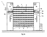
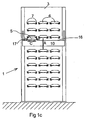
- the exemplary embodiment 1 shown in figures 1A-C is substantially column-shaped and comprises a frame 2 having two elevator shafts 3a,3b at two longitudinal ends and storage sections borne in between them, in this case storage levels 4, in this example nine, which in this example are positioned in three columns.
- storage levels 4 in this example nine, which in this example are positioned in three columns.
- a platform 5a,b is accommodated, which can be moved up and down by electromotors 13a,b, direction A.
- a number of carriers or holders for articles are housed.
- Each platform 5a,b is supported on a frame 11a,b and comprises a belt conveyor 8a,b that is drivable by means of electromotors 12a,b. On the belts 8a,b pushers 9a,b are attached for movement along with them.
- the belts 8a,b have a support surface of approximately 2L, wherein L is the length of a holder 6, measured in main direction of a storage level 4, in this example corresponding with a module size.
- the frames 11a,b with platforms 5a,b are supported on a frame 10a,b by wheels 17a,b and can be moved in the direction C over rails 16a,b by means of electromotors, not shown, provided on the platforms.
- Each storage level 4 comprises two support profiles 7, on which a series of holders 6 is supported, in a way so as to be easily shiftable in the direction B.
- the support profiles 7 have a support length of approximately a full number of lengths L of the holder 6, in this example 12L.
- control unit 14 For controlling the said electromotors a control unit 14 with programmable computer 15 is present.
- the holders 6 are provided with unique identification marks, such as a barcode.
- a barcode For reading the barcodes sensors are present, that are functionally connected to the control unit 14/computer 15.
- the control unit 14 a connection can be made between a holder and an article placed thereon, so that it is exactly known at what location in the device an article is situated and which article it is.
- One of the storage sections 4 can be suitable for entry, for instance level 4a, and one for exit for instance level 4b.
- the entry level 4a and the exit level 4b can be situated at opposite main sides of the device 1, so that the direction of entry V can be the same as the direction of exit T, see figure 4 .
- the entry and exit levels are situated at a level which to a person involved in entering/discharging, is ergonomically advantageous.
- the articles When storing a group of identical articles Pi the articles are placed in the direction V on or in the holders 6 of entry level 4a.
- the platforms 5a,b have been brought at the same level and in line with the entry level 4a.
- the belt 8b After loading the belt 8b is activated.
- On the belt 8b there are two empty holders 6, on belt 8a none, so that the overall number of holders on platforms and storage levels is 3 x 9 x 12 + 2.
- the pusher 9b said holders 6 are pushed at the right-hand side onto the support profiles 7 of the entry level. Said pushing force is transferred via the holders 6 of said level to the two most left holders 6 that are each carrying an article Pi. All holders 6 thus shift onwards to the left, while discharging the two loaded holders 6 to the belt 8a, direction D2.
- the belt 8a can then be idle or be driven synchronously.
- the belt 8a is activated in order to urge the loaded holders 6 by means of pusher 9a to the right, direction F1, onto the support profiles 7 of said level.
- the platforms 5a,b can be moved downwards again, direction G, in order to be brought in line again with entry level 4a, after which the same process can start over again. This can be repeated as long as there are still empty holders at the selected storage level. After that another storage level can be used.
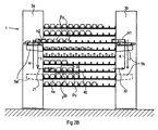
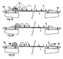
- platform 5a When the articles Pi are different and for that reason have to be stored at different storage levels, platform 5a will be used for first discharging one article Pi to the one selected storage level, and subsequently the next, different article on another selected storage level. This is for instance shown in figures 3A-C , where the article b is discharged to a storage level, but a different article c is still kept on the belt 8a. As shown, at the end of discharging, the belts 8a,b can be driven in a slightly opposite manner, in order to make the holder 6 with article c and the empty holder on belt 8b entirely free from the storage level, before moving the platforms 5a,b.
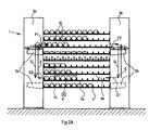
- the platforms 5a,b are brought in line with the selected storage level 4 ( figure 2B ).
- Belt 8b is subsequently driven in order to push the empty holders 6 on it to the left, direction H1, by means of pusher 9b.
- two loaded holders 6 are urged onto the belt 8a, direction H2.
- the platforms 5a,b are moved downwards, direction I, until they are in line, optionally after movement in direction C ( figure 1C ), with exit level 4b.
- the belt 8a is activated, so that by means of the pusher 9a two loaded holders 6 are urged in the direction J1 onto the support profiles 7 of the exit level 4b.
- the articles Pu can be removed in the direction T from the exit level 4b, via passage 20.
- the holders can also be loaded with a multiple of articles, or a combination of articles, for instance a package of medicines customized to a patient.
- the holders 6 can also be designed so as to be multiple, having multiple compartments.
- the holders can be substantially U-shaped, wherein the legs form upright edges or walls that are transverse to said main direction.
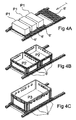
- FIGS. 4A-C it is also possible to use holders 6 that do not have upright walls or edges that are transverse to the main direction, but as shown, merge into each other with their support surfaces.
- An advantage thereof is that adjacently situated holders are able to offer a large support surface, as a result of which articles that are larger than one holder can also be handled.
- the holders 6' each carry one article, a box P1, in figure 4B four holders 6' together carry two crates P2, in figure 4C the four holders 6' together carry one larger crate P3.
- the platforms will be adapted thereto as regards length.
- a supply conveyor 150 is positioned, on which multiple holders 106 with four compartments a-d.
- the filler places the articles (direction S) in an empty holder 106, that arrives in direction W1.
- the loaded holder 106 runs, directions W2, W3, to the location of entry, where an ejector that is not shown delivers the articles in the direction V to a holder 106 on the entry level 104a.
- said holder 106 later ends up on platform 105a, which in this example by way of example is adapted for supporting one holder 106.
Landscapes
- Engineering & Computer Science (AREA)
- Mechanical Engineering (AREA)
- Warehouses Or Storage Devices (AREA)
Claims (15)
- Vorrichtung (1), um Artikel (P) zu lagern und daraus Gruppen von Artikeln (P) zu bilden, umfassend einen Rahmen (2) mit einer ersten Reihe von zueinander parallelen länglichen Lagerabschnitten (4), die sich zwischen einem ersten Ende und einem zweiten Ende des Rahmens (2) erstrecken, darüber hinaus umfassend eine Anzahl von Haltern (6), wie etwa Trägern, für die Artikel, wobei die Lagerabschnitte (4) mit Halterstützen (7) versehen sind, worauf eine Anzahl der Halter (6) zur Lagerung der Artikel (P) getragen werden kann, wobei an dem ersten Ende und an dem zweiten Ende des Rahmens (2) eine erste bzw. eine zweite Plattform (5a; 5b) angeordnet sind, die jeweils dazu geeignet ist, wenigstens einen Halter (6) aufzunehmen und vorzugsweise mehr als einen Halter (6) zu tragen; und erste Bewegungsmittel (13a, b), um die Plattformen (5a; 5b) gleichzeitig von dem einen Lagerabschnitt zu einem anderen Lagerabschnitt zu bewegen, wobei die Vorrichtung mit zweiten Bewegungsmitteln (8a, b; 12a, b) versehen ist, um wenigstens einen Halter (6) Horizontal von der Plattform (5a) an dem ersten Ende des Rahmens (2) zu den Halterstützen (7) eines gewählten Lagerabschnitts (5) zu bewegen, während ein oder mehrere Halter (6), der bzw. die eine gleiche Halterlänge (L) darstellt bzw. darstellen, von dem gewählten Lagerabschnitt (4) zu der Plattform (5b) an dem zweiten Ende des Rahmens (2) bewegt wird bzw. werden, wobei die zweiten Bewegungsmittel (8a, b; 12a, b) auch bereitgestellt sind, um wenigstens einen Halter (6) von der Plattform (5b) an dem zweiten Ende des Rahmens (2) zu den Halterstützen (7) eines gewählten Lagerabschnitts (4) zu bewegen, während ein oder mehrere Halter (6), der bzw. die eine gleiche Halterlänge (L) darstellt bzw. darstellen, von dem Lagerabschnitt (4) zu der Plattform (5a) an dem ersten Ende des Rahmens (2) bewegt wird bzw. werden, dadurch gekennzeichnet, dass die Vorrichtung mit einem programmierbaren Steuersystem (14, 15) versehen ist, um die Bewegungsmittel (8a, b; 12a, b) zu steuern, wobei das Steuersystem (14, 15) so programmiert ist, dass die Artikel (P) ausschließlich durch die erste Plattform (5a) an den Enden der Lagerabschnitte (4) entlang bewegt werden und die leeren Halter ausschließlich durch die zweite Plattform (5b) bewegt werden.
- Vorrichtung nach Anspruch 1, wobei die zweiten Bewegungsmittel (8a, b; 12a, b) an der ersten und/oder der zweiten Plattform (5a, 5b) bereitgestellt sind, wobei, vorzugsweise, die zweiten Bewegungsmittel (8a, b; 12a, b) direkt mit einem Halter (6) an dem Ende der Reihe von Haltern (6), die auf dem Lagerabschnitt (4) mit beiden Plattformen (5a; 5b) gelegen ist, eingreifen, oder die zweiten Bewegungsmittel (8a, b; 12a, b) mit einem Halter (6), der auf einer Plattform (5a; 5b) gelegen ist, eingreifen und insbesondere als ein Schieber (9a, 9b) gestaltet sind.
- Vorrichtung nach Anspruch 1 oder 2, wobei die Halter (6) eine Horizontale Abmessung (L) in der Richtung des Lagerabschnitts (4) aufweisen, die ein Einfaches einer Modulgröße ist, und wobei jeder Lagerabschnitt (4) eine Anzahl von N1 Haltern (6) trägt und die Anzahl der Lagerabschnitte (4) N2 beträgt, wobei die Anzahl der Halter (6) in der Vorrichtung wenigstens N1 x N2 + 2 beträgt, wobei die Höchstanzahl von Haltern (6), die durch eine Plattform (5a, 5b) aufgenommen werden kann, N3 beträgt, wobei die Anzahl der Halter (6) in der Vorrichtung wenigstens N1 x N2 + N3 beträgt.
- Vorrichtung nach Anspruch 1 oder 2, wobei ein oder mehrere Halter (6) eine Horizontale Abmessung (L) in der Richtung des Lagerabschnitts (4) aufweist bzw. aufweisen, die ein Vielfaches einer Modulgröße ist, wobei im Fall einer gegebenen Anzahl der Lagerabschnitte (4) von N2 und einer Anzahl von Modulgrößen von N4 pro Lagerabschnitt (4) die gesamte durch Halter (6) eingenommene Länge wenigstens N2 x N4 + 2 beträgt, wobei die Höchstanzahl von Modulgrößen, die eine Plattform (5a, 5b) enthalten kann, N5 beträgt, und die gesamte Länge, die durch die Halter (6) eingenommen wird, N2 x N4 + N5 beträgt.
- Vorrichtung nach einem der vorhergehenden Ansprüche, wobei wenigstens einer der Lagerabschnitte (4a, 4b) dazu geeignet ist, eine Bewegung der Artikel (P), die durch ihre Halter (6) gehalten werden, in eine Richtung, die quer zu dem betreffenden Lagerabschnitt (4) verläuft, zu gestatten, um Artikel (P) an die Vorrichtung abzugeben bzw. von dieser zu erhalten.
- Vorrichtung nach einem der vorhergehenden Ansprüche, wobei der Rahmen (2) mit wenigstens einer zweiten Reihe von zueinander parallelen länglichen Lagerabschnitten (4) versehen ist, die sich zwischen einem ersten Ende und einem zweiten Ende des Rahmens (2) erstrecken, wobei die erste und die zweite Reihe übereinander oder nebeneinander positioniert sind, und die Vorrichtung mit dritten Bewegungsmitteln (16a, b; 17a, b) versehen ist, um die Plattformen (5a, 5b) gleichzeitig von einer Position in einer Linie mit einem Lagerabschnitt (4) der einen Reihe zu einer Position in einer Linie mit einem Lagerabschnitt (4) der zweiten Reihe zu bewegen.
- Vorrichtung nach Anspruch 5 und 6, wobei wenigstens zwei der Lagerabschnitte (4a, 4b) dazu geeignet sind, eine Bewegung der Artikel (P), die durch ihre Halter (6) gehalten werden, in eine Richtung, die quer zu dem betreffenden Lagerabschnitt (4) verläuft, zu gestatten, um Artikel (P) an die Vorrichtung abzugeben bzw. von dieser zu erhalten, wobei die beiden Lagerabschnitte (4) in einer unterschiedlichen Reihe gelegen sind, wobei, vorzugsweise, die Halter (6) in einer Richtung, die quer zu dem betreffenden Lagerabschnitt (4) verläuft, entfernt werden können.
- Vorrichtung nach einem der vorhergehenden Ansprüche, wobei die erste Reihe von Lagerabschnitten (4) eine Säule bildet, in der die Lagerabschnitte (4) übereinander gelegen sind.
- Verfahren, um Artikel zu lagern, wobei die Artikel (P) in einer Vorrichtung gelagert werden, wobei die Vorrichtung einen Rahmen (2) umfasst, der eine erste Reihe von länglichen Lagerabschnitten (4) aufweist, die parallel zueinander angeordnet sind und sich zwischen einem ersten Ende und einem zweiten Ende des Rahmens (2) erstrecken, und darüber hinaus eine Anzahl von Haltern (6) für die Artikel (P) umfasst, wobei die Lagerabschnitte (4) mit Halterstützen (7) versehen sind, auf denen eine Anzahl der Halter (6) getragen werden kann, um die Artikel (P) zu lagern, wobei an dem ersten Ende und dem zweiten Ende des Rahmens (2) eine erste bzw. eine zweite Plattform (5a; 5b) angeordnet sind, dadurch gekennzeichnet, dass ein gelieferter Artikel (P) auf einem Halter (6) angeordnet wird und zusammen mit dem Halter (6) ausschließlich durch die erste Plattform (5a) zu einem gewählten Lagerabschnitt (4) befördert wird, wobei der gegenständliche Halter (6) von der ersten Plattform (5a) auf den Halterstützen des Lagerabschnitts (4) aufgenommen wird, während ein leerer Halter (6) von dem gleichen Lagerabschnitt (4) zu der zweiten Plattform (5b) abgegeben wird, wobei die zweite Plattform (5b) zur Bewegung von ausschließlich leeren Haltern (6) verwendet wird.
- Verfahren nach Anspruch 9, wobei zum Holen der Artikel (P) aus dem Lager die erste Plattform (5a) und die zweite Plattform (5b) zu einem gewählten Lagerabschnitt (4) gebracht werden und ein leerer Halter (6) von der zweiten Plattform (5b) auf den Halterstützen (7) des Lagerabschnitts (4) aufgenommen wird, während ein Halter (6) mit einem Artikel (P) von dem Lagerabschnitt (4) zu der ersten Plattform (5a) abgegeben wird, wonach der Halter (6) mit dem Artikel (P) von der ersten Plattform (5a) zu einer Stelle zur Abgabe des Artikels (P) befördert wird, wobei die zweite Plattform (5b) zur Bewegung von ausschließlich leeren Haltern (6) verwendet wird.
- Verfahren nach Anspruch 9 oder 10, wobei die Abgabe eines Halters (6) von einer Plattform (5a; 5b) durch Ausüben einer Schubkraft auf den Halter (6) stattfindet, wobei die Schubkraft verwendet wird, um einen Halter (6) an die andere Plattform (5a; 5b) abzugeben.
- Verfahren nach Anspruch 9, 10 oder 11, wobei für jeden Halter (6), der mit einem Artikel (P) versehen ist und durch einen Abschnitt (4) von der ersten Plattform (5a) aufgenommen wird, ein leerer Halter (6) des gleichen Abschnitts (4) an die zweite Plattform (5b) abgegeben wird, und/oder wobei für jeden leeren Halter (6) der durch einen Lagerabschnitt (4) von der zweiten Plattform (5b) aufgenommen wird, ein Halter (6), der mit einem Artikel (P) versehen ist, von dem gleichen Lagerabschnitt (4) an die erste Plattform (5a) abgegeben wird.
- Verfahren nach einem der Ansprüche 9 bis 12, wobei ein erster und ein zweiter gelieferter Artikel (P) auf einem ersten bzw. einem zweiten Halter (6) angeordnet werden und damit durch die erste Plattform (5a) zu wenigstens einem gewählten Lagerabschnitt (4) befördert werden, wobei die Halter (6) von der ersten Plattform (5a) auf den Halterstützen (7) des wenigstens einen gewählten Lagerabschnitts (4) aufgenommen werden, während leere Halter (6) von dem wenigstens einen gewählten Lagerabschnitt (4) an die zweite Plattform (5b) abgegeben werden, wobei die Artikel (P) bei Lieferung in dem ersten und zweiten Halter (6) angeordnet werden, wenn sie sich in einem Zugangsabschnitt befinden, der in der Gruppe enthalten ist, wobei der erste und der zweite Halter (6) von dem Zugangsabschnitt auf die erste Plattform (5a) befördert werden, während leere Halter (6) von der zweiten Plattform (5b) zu dem Zugangsabschnitt abgegeben werden, wobei, vorzugsweise, die Artikel (P) bei Lieferung in dem Zugangsabschnitt gemäß einer im Wesentlichen Horizontalen Zugangsrichtung, die quer zu einer senkrechten Ebene verläuft, welche die erste und die zweite Plattform (5a; 5b) enthält, vorzugsweise an einer Vorderseite der Vorrichtung, in dem ersten und dem zweiten Halter (6) angeordnet werden.
- Verfahren nach einem der Ansprüche 9 bis 13, wobei ein erster und ein zweiter gelieferter Artikel (P) auf einem ersten bzw. einem zweiten Halter (6) angeordnet werden und damit durch die erste Plattform (5a) zu wenigstens einem gewählten Lagerabschnitt (6) befördert werden, wobei die Halter (6) von der ersten Plattform (5a) auf den Halterstützen (7) des wenigstens einen gewählten Lagerabschnitts (4) aufgenommen werden, während leere Halter (6) von dem wenigstens einen gewählten Lagerabschnitt (4) an die zweite Plattform (5b) abgegeben werden, wobei zum Holen eines ersten und eines zweiten Artikels (P) aus dem Lager, welche Artikel (P) durch einen ersten bzw. zweiten Halter (6) gehalten werden, die erste Plattform (5a) und die zweite Plattform (5b) zu dem wenigstens einen gewählten Lagerabschnitt (4) befördert werden, leere Halter (6) von der zweiten Plattform (5b) auf dem wenigstens einen gewählten Lagerabschnitt (4) aufgenommen werden, während der erste und der zweite Halter (6) an die erste Plattform (5a) abgegeben werden, wonach der erste und der zweite Halter (6) mit den Artikeln (P) durch die erste Plattform (5a) an eine Stelle zur Abgabe der Artikel (P) befördert werden; wobei der erste und der zweite Halter (6) zum Abgeben der Artikel (P) auf einem Ausgangsabschnitt, der in der Gruppe enthalten ist, angeordnet werden, wobei der erste und der zweite Halter (6) von der ersten Plattform (5b) an den Ausgangsabschnitt abgegeben werden, während leere Halter (6) von dem Ausgangsabschnitt an die zweite Plattform (5b) abgegeben werden, wobei, vorzugsweise, die Artikel (P) für den Ausgang gemäß einer im Wesentlichen Horizontalen Richtung, die quer zu einer senkrechten Ebene verläuft, welche die erste und die zweite Plattform (5a; 5b) enthält, vorzugsweise an einer Rückseite der Vorrichtung, aus dem Ausgangsabschnitt entnommen werden.
- Verfahren nach Anspruch 13 oder 14, wobei dann, wenn der erste und der zweite Artikel (P) geliefert werden, der erste Halter (6) auf einem ersten gewählten Lagerabschnitt (4) angeordnet wird und der zweite Halter (6) auf einem anderen, zweiten gewählten Lagerabschnitt (4) angeordnet wird, wobei dann, wenn der erste und der zweite Artikel (P) geholt werden, der erste Halter (6) von einem ersten gewählten Lagerabschnitt (4) erhalten wird und der zweite Halter (6) von einem anderen zweiten gewählten Lagerabschnitt (4) erhalten wird.
Priority Applications (1)
| Application Number | Priority Date | Filing Date | Title |
|---|---|---|---|
| EP14002531.3A EP2907773A1 (de) | 2009-02-04 | 2010-02-02 | Lager- und Kommissioniersystem |
Applications Claiming Priority (2)
| Application Number | Priority Date | Filing Date | Title |
|---|---|---|---|
| NL1036512A NL1036512C2 (nl) | 2009-02-04 | 2009-02-04 | Opslag- en orderverzamelsysteem. |
| PCT/NL2010/000015 WO2010090512A1 (en) | 2009-02-04 | 2010-02-02 | Storage and order collection system |
Related Child Applications (1)
| Application Number | Title | Priority Date | Filing Date |
|---|---|---|---|
| EP14002531.3A Division EP2907773A1 (de) | 2009-02-04 | 2010-02-02 | Lager- und Kommissioniersystem |
Publications (2)
| Publication Number | Publication Date |
|---|---|
| EP2393734A1 EP2393734A1 (de) | 2011-12-14 |
| EP2393734B1 true EP2393734B1 (de) | 2014-07-23 |
Family
ID=41100484
Family Applications (2)
| Application Number | Title | Priority Date | Filing Date |
|---|---|---|---|
| EP10703130.4A Active EP2393734B1 (de) | 2009-02-04 | 2010-02-02 | Lager- und kommissioniersystem |
| EP14002531.3A Withdrawn EP2907773A1 (de) | 2009-02-04 | 2010-02-02 | Lager- und Kommissioniersystem |
Family Applications After (1)
| Application Number | Title | Priority Date | Filing Date |
|---|---|---|---|
| EP14002531.3A Withdrawn EP2907773A1 (de) | 2009-02-04 | 2010-02-02 | Lager- und Kommissioniersystem |
Country Status (6)
| Country | Link |
|---|---|
| US (2) | US9254958B2 (de) |
| EP (2) | EP2393734B1 (de) |
| CN (1) | CN102317183B (de) |
| ES (1) | ES2507590T3 (de) |
| NL (1) | NL1036512C2 (de) |
| WO (1) | WO2010090512A1 (de) |
Cited By (1)
| Publication number | Priority date | Publication date | Assignee | Title |
|---|---|---|---|---|
| WO2025124779A1 (de) * | 2023-12-12 | 2025-06-19 | Ssi Schäfer Automation Gmbh (At) | Insektenaufzuchtsystem |
Families Citing this family (17)
| Publication number | Priority date | Publication date | Assignee | Title |
|---|---|---|---|---|
| NL1038148C2 (nl) * | 2010-08-03 | 2012-02-13 | Ferdar Automation Technology Nederland B V | Opslag- en orderverzamelsysteem. |
| NL1038714C2 (nl) | 2011-03-30 | 2012-10-02 | Ferdar Automation Technology Nederland B V | Opslag- en/of orderverzamelsysteem. |
| ITVI20130214A1 (it) * | 2013-08-09 | 2015-02-10 | Idea Srl | Magazzino automatico |
| WO2015045711A1 (ja) * | 2013-09-30 | 2015-04-02 | 村田機械株式会社 | 保管庫 |
| CN104670877B (zh) * | 2015-01-08 | 2017-04-05 | 北京七星华创电子股份有限公司 | 一种晶硅太阳能电池片料架的暂存装置 |
| NL1041164B1 (nl) | 2015-01-30 | 2016-10-12 | I-Collector Holding B V | Inrichting en werkwijze voor het beheren van de opslag van artikelen. |
| WO2016122309A1 (en) | 2015-01-30 | 2016-08-04 | I-Collector Holding B.V. | Apparatus and method for managing the storage of articles |
| CN106986156A (zh) * | 2017-05-05 | 2017-07-28 | 江苏三工建材科技有限公司 | 一种基于plc的砌块预养输送系统及其输送方法 |
| NL2020107B1 (nl) | 2017-12-18 | 2019-06-25 | I Collector Holding Bv | Inrichting voor opslag van artikelen |
| CN110466927B (zh) * | 2018-05-09 | 2021-01-12 | 菜鸟智能物流控股有限公司 | 一种仓库及仓库的储物对象、货架处理方法 |
| CN108438795A (zh) * | 2018-05-15 | 2018-08-24 | 横店集团东磁股份有限公司 | 一种从磁瓦成型到窑炉烧结的自动化生产线及其实现方法 |
| CN108545391B (zh) * | 2018-06-13 | 2020-03-24 | 盐城工学院 | 还书小车及还书控制方法 |
| JP7040412B2 (ja) * | 2018-11-14 | 2022-03-23 | 株式会社豊田自動織機 | 倉庫システム |
| EP3972912A4 (de) | 2019-05-20 | 2023-04-26 | Carnegie Mellon University | Automatisiertes regalbedienungssystem mit hoher dichte |
| KR20220160056A (ko) * | 2020-03-31 | 2022-12-05 | 오토스토어 테크놀로지 에이에스 | 다수의 로우를 갖는 자동화 보관 타워 |
| IT202000011974A1 (it) * | 2020-05-21 | 2021-11-21 | Immobiliare Metalprogetti S R L | Magazzino automatizzato |
| CN112830139B (zh) * | 2020-12-29 | 2022-04-12 | 全屋优品科技(深圳)有限公司 | 一种基于saas云服务的智能仓储系统及数据同步方法 |
Family Cites Families (13)
| Publication number | Priority date | Publication date | Assignee | Title |
|---|---|---|---|---|
| GB1068833A (en) | 1963-04-19 | 1967-05-17 | Donald Mayer King | Improvements in or relating to storage systems |
| GB1389221A (en) | 1971-07-16 | 1975-04-03 | Bright T J R | Load storage systems and apparatus therefore |
| JPH03125707A (ja) | 1989-10-12 | 1991-05-29 | Mitsubishi Heavy Ind Ltd | 橋梁の架設工法 |
| JPH03125707U (de) * | 1989-12-28 | 1991-12-19 | ||
| JPH0442104A (ja) | 1990-06-07 | 1992-02-12 | Nec Corp | 波長分割多重送受信モジュール |
| JPH0442104U (de) * | 1990-08-10 | 1992-04-09 | ||
| DE4205001C2 (de) | 1992-02-19 | 1995-11-09 | Dambach Ind Anlagen | Regalbediengerät mit einem Horizontalförderer als Speichereinrichtung mit mehreren Speicherplätzen |
| DE19636564A1 (de) * | 1996-09-09 | 1998-03-12 | Franz Daub | Verfahren und Anordnung zum Fördern einer Mehrzahl von Backgutträgern durch einen Gär- oder Backraum |
| US6061607A (en) * | 1997-07-18 | 2000-05-09 | St. Onge Company | Order pick system |
| KR19990035554A (ko) | 1997-10-31 | 1999-05-15 | 윤종용 | 스토커 설비 구조 |
| DE19941640B4 (de) * | 1998-09-01 | 2009-04-02 | Kht Kommissionier- Und Handhabungstechnik Gmbh | Verfahren zur rechnergesteuerten Lagerung von Stückgut und ein zugehöriges Regallagersystem, insbesondere für die Kommissionierung von Arzneimittelpackungen |
| DE10058625A1 (de) * | 2000-11-25 | 2002-06-06 | Seemi Soc D Etudes D Equipemen | Etagenpalette |
| EP1401743B1 (de) * | 2001-07-04 | 2005-09-28 | TGW Transportgeräte GmbH | Transportwagen zum ein- und auslagern von transportgut |
-
2009
- 2009-02-04 NL NL1036512A patent/NL1036512C2/nl active
-
2010
- 2010-02-02 US US13/147,253 patent/US9254958B2/en active Active
- 2010-02-02 EP EP10703130.4A patent/EP2393734B1/de active Active
- 2010-02-02 EP EP14002531.3A patent/EP2907773A1/de not_active Withdrawn
- 2010-02-02 WO PCT/NL2010/000015 patent/WO2010090512A1/en not_active Ceased
- 2010-02-02 CN CN201080006389.0A patent/CN102317183B/zh active Active
- 2010-02-02 ES ES10703130.4T patent/ES2507590T3/es active Active
-
2016
- 2016-01-08 US US14/991,030 patent/US9975697B2/en active Active
Cited By (1)
| Publication number | Priority date | Publication date | Assignee | Title |
|---|---|---|---|---|
| WO2025124779A1 (de) * | 2023-12-12 | 2025-06-19 | Ssi Schäfer Automation Gmbh (At) | Insektenaufzuchtsystem |
Also Published As
| Publication number | Publication date |
|---|---|
| US20160137415A1 (en) | 2016-05-19 |
| US9254958B2 (en) | 2016-02-09 |
| US9975697B2 (en) | 2018-05-22 |
| CN102317183B (zh) | 2017-06-06 |
| ES2507590T3 (es) | 2014-10-15 |
| US20110318145A1 (en) | 2011-12-29 |
| EP2907773A1 (de) | 2015-08-19 |
| NL1036512C2 (nl) | 2010-08-12 |
| CN102317183A (zh) | 2012-01-11 |
| EP2393734A1 (de) | 2011-12-14 |
| WO2010090512A1 (en) | 2010-08-12 |
Similar Documents
| Publication | Publication Date | Title |
|---|---|---|
| EP2393734B1 (de) | Lager- und kommissioniersystem | |
| EP2601117B1 (de) | System zur lagerung und kommissionierung | |
| CN113335814B (zh) | 排序系统和方法 | |
| KR102732476B1 (ko) | 피킹 시스템 | |
| US9340355B2 (en) | Storage and/or order collection system | |
| US5672039A (en) | Order consolidation indexing system | |
| US8494673B2 (en) | Warehouse system and method for operating the same | |
| NL1037378C2 (nl) | Werkwijze voor het verzamelen van een aantal verschillende, tot een opdracht behorende, producten, stellingsbedienapparaat voor toepassing in een dergelijke werkwijze en systeem voor het verzamelen van verschillende producten op een verzamelpallet. | |
| US9429930B2 (en) | Automated order-picking station for the manual picking of articles from storage containers into an order container | |
| CN108146948A (zh) | 用于存入和取出物体的方法以及用于执行该方法的仓储系统 | |
| KR20190133616A (ko) | 피킹 시스템 | |
| WO2014189388A1 (en) | System and method for creating a structured set of containers | |
| US10745200B2 (en) | Method and system for commissioning products | |
| JP4732796B2 (ja) | 仕分け装置 | |
| JPH082620A (ja) | ピッキング装置 |
Legal Events
| Date | Code | Title | Description |
|---|---|---|---|
| PUAI | Public reference made under article 153(3) epc to a published international application that has entered the european phase |
Free format text: ORIGINAL CODE: 0009012 |
|
| 17P | Request for examination filed |
Effective date: 20110830 |
|
| AK | Designated contracting states |
Kind code of ref document: A1 Designated state(s): AT BE BG CH CY CZ DE DK EE ES FI FR GB GR HR HU IE IS IT LI LT LU LV MC MK MT NL NO PL PT RO SE SI SK SM TR |
|
| RAP1 | Party data changed (applicant data changed or rights of an application transferred) |
Owner name: I-COLLECTOR HOLDING B.V. |
|
| DAX | Request for extension of the european patent (deleted) | ||
| GRAP | Despatch of communication of intention to grant a patent |
Free format text: ORIGINAL CODE: EPIDOSNIGR1 |
|
| INTG | Intention to grant announced |
Effective date: 20130508 |
|
| GRAP | Despatch of communication of intention to grant a patent |
Free format text: ORIGINAL CODE: EPIDOSNIGR1 |
|
| INTG | Intention to grant announced |
Effective date: 20131008 |
|
| GRAS | Grant fee paid |
Free format text: ORIGINAL CODE: EPIDOSNIGR3 |
|
| GRAA | (expected) grant |
Free format text: ORIGINAL CODE: 0009210 |
|
| AK | Designated contracting states |
Kind code of ref document: B1 Designated state(s): AT BE BG CH CY CZ DE DK EE ES FI FR GB GR HR HU IE IS IT LI LT LU LV MC MK MT NL NO PL PT RO SE SI SK SM TR |
|
| REG | Reference to a national code |
Ref country code: GB Ref legal event code: FG4D |
|
| REG | Reference to a national code |
Ref country code: CH Ref legal event code: EP |
|
| REG | Reference to a national code |
Ref country code: IE Ref legal event code: FG4D |
|
| REG | Reference to a national code |
Ref country code: AT Ref legal event code: REF Ref document number: 678726 Country of ref document: AT Kind code of ref document: T Effective date: 20140815 |
|
| REG | Reference to a national code |
Ref country code: DE Ref legal event code: R096 Ref document number: 602010017682 Country of ref document: DE Effective date: 20140904 |
|
| REG | Reference to a national code |
Ref country code: ES Ref legal event code: FG2A Ref document number: 2507590 Country of ref document: ES Kind code of ref document: T3 Effective date: 20141015 Ref country code: NL Ref legal event code: T3 |
|
| REG | Reference to a national code |
Ref country code: LT Ref legal event code: MG4D |
|
| PG25 | Lapsed in a contracting state [announced via postgrant information from national office to epo] |
Ref country code: BG Free format text: LAPSE BECAUSE OF FAILURE TO SUBMIT A TRANSLATION OF THE DESCRIPTION OR TO PAY THE FEE WITHIN THE PRESCRIBED TIME-LIMIT Effective date: 20141023 Ref country code: GR Free format text: LAPSE BECAUSE OF FAILURE TO SUBMIT A TRANSLATION OF THE DESCRIPTION OR TO PAY THE FEE WITHIN THE PRESCRIBED TIME-LIMIT Effective date: 20141024 Ref country code: LT Free format text: LAPSE BECAUSE OF FAILURE TO SUBMIT A TRANSLATION OF THE DESCRIPTION OR TO PAY THE FEE WITHIN THE PRESCRIBED TIME-LIMIT Effective date: 20140723 Ref country code: PT Free format text: LAPSE BECAUSE OF FAILURE TO SUBMIT A TRANSLATION OF THE DESCRIPTION OR TO PAY THE FEE WITHIN THE PRESCRIBED TIME-LIMIT Effective date: 20141124 Ref country code: NO Free format text: LAPSE BECAUSE OF FAILURE TO SUBMIT A TRANSLATION OF THE DESCRIPTION OR TO PAY THE FEE WITHIN THE PRESCRIBED TIME-LIMIT Effective date: 20141023 Ref country code: FI Free format text: LAPSE BECAUSE OF FAILURE TO SUBMIT A TRANSLATION OF THE DESCRIPTION OR TO PAY THE FEE WITHIN THE PRESCRIBED TIME-LIMIT Effective date: 20140723 Ref country code: SE Free format text: LAPSE BECAUSE OF FAILURE TO SUBMIT A TRANSLATION OF THE DESCRIPTION OR TO PAY THE FEE WITHIN THE PRESCRIBED TIME-LIMIT Effective date: 20140723 |
|
| PG25 | Lapsed in a contracting state [announced via postgrant information from national office to epo] |
Ref country code: PL Free format text: LAPSE BECAUSE OF FAILURE TO SUBMIT A TRANSLATION OF THE DESCRIPTION OR TO PAY THE FEE WITHIN THE PRESCRIBED TIME-LIMIT Effective date: 20140723 Ref country code: IS Free format text: LAPSE BECAUSE OF FAILURE TO SUBMIT A TRANSLATION OF THE DESCRIPTION OR TO PAY THE FEE WITHIN THE PRESCRIBED TIME-LIMIT Effective date: 20141123 Ref country code: CY Free format text: LAPSE BECAUSE OF FAILURE TO SUBMIT A TRANSLATION OF THE DESCRIPTION OR TO PAY THE FEE WITHIN THE PRESCRIBED TIME-LIMIT Effective date: 20140723 Ref country code: HR Free format text: LAPSE BECAUSE OF FAILURE TO SUBMIT A TRANSLATION OF THE DESCRIPTION OR TO PAY THE FEE WITHIN THE PRESCRIBED TIME-LIMIT Effective date: 20140723 Ref country code: LV Free format text: LAPSE BECAUSE OF FAILURE TO SUBMIT A TRANSLATION OF THE DESCRIPTION OR TO PAY THE FEE WITHIN THE PRESCRIBED TIME-LIMIT Effective date: 20140723 |
|
| REG | Reference to a national code |
Ref country code: DE Ref legal event code: R097 Ref document number: 602010017682 Country of ref document: DE |
|
| PG25 | Lapsed in a contracting state [announced via postgrant information from national office to epo] |
Ref country code: EE Free format text: LAPSE BECAUSE OF FAILURE TO SUBMIT A TRANSLATION OF THE DESCRIPTION OR TO PAY THE FEE WITHIN THE PRESCRIBED TIME-LIMIT Effective date: 20140723 Ref country code: SK Free format text: LAPSE BECAUSE OF FAILURE TO SUBMIT A TRANSLATION OF THE DESCRIPTION OR TO PAY THE FEE WITHIN THE PRESCRIBED TIME-LIMIT Effective date: 20140723 Ref country code: DK Free format text: LAPSE BECAUSE OF FAILURE TO SUBMIT A TRANSLATION OF THE DESCRIPTION OR TO PAY THE FEE WITHIN THE PRESCRIBED TIME-LIMIT Effective date: 20140723 Ref country code: RO Free format text: LAPSE BECAUSE OF FAILURE TO SUBMIT A TRANSLATION OF THE DESCRIPTION OR TO PAY THE FEE WITHIN THE PRESCRIBED TIME-LIMIT Effective date: 20140723 Ref country code: CZ Free format text: LAPSE BECAUSE OF FAILURE TO SUBMIT A TRANSLATION OF THE DESCRIPTION OR TO PAY THE FEE WITHIN THE PRESCRIBED TIME-LIMIT Effective date: 20140723 |
|
| PLBE | No opposition filed within time limit |
Free format text: ORIGINAL CODE: 0009261 |
|
| STAA | Information on the status of an ep patent application or granted ep patent |
Free format text: STATUS: NO OPPOSITION FILED WITHIN TIME LIMIT |
|
| 26N | No opposition filed |
Effective date: 20150424 |
|
| PG25 | Lapsed in a contracting state [announced via postgrant information from national office to epo] |
Ref country code: LU Free format text: LAPSE BECAUSE OF FAILURE TO SUBMIT A TRANSLATION OF THE DESCRIPTION OR TO PAY THE FEE WITHIN THE PRESCRIBED TIME-LIMIT Effective date: 20150202 |
|
| PG25 | Lapsed in a contracting state [announced via postgrant information from national office to epo] |
Ref country code: MC Free format text: LAPSE BECAUSE OF FAILURE TO SUBMIT A TRANSLATION OF THE DESCRIPTION OR TO PAY THE FEE WITHIN THE PRESCRIBED TIME-LIMIT Effective date: 20140723 |
|
| REG | Reference to a national code |
Ref country code: IE Ref legal event code: MM4A |
|
| PG25 | Lapsed in a contracting state [announced via postgrant information from national office to epo] |
Ref country code: SI Free format text: LAPSE BECAUSE OF FAILURE TO SUBMIT A TRANSLATION OF THE DESCRIPTION OR TO PAY THE FEE WITHIN THE PRESCRIBED TIME-LIMIT Effective date: 20140723 |
|
| PG25 | Lapsed in a contracting state [announced via postgrant information from national office to epo] |
Ref country code: IE Free format text: LAPSE BECAUSE OF NON-PAYMENT OF DUE FEES Effective date: 20150202 |
|
| REG | Reference to a national code |
Ref country code: FR Ref legal event code: PLFP Year of fee payment: 7 |
|
| PG25 | Lapsed in a contracting state [announced via postgrant information from national office to epo] |
Ref country code: MT Free format text: LAPSE BECAUSE OF FAILURE TO SUBMIT A TRANSLATION OF THE DESCRIPTION OR TO PAY THE FEE WITHIN THE PRESCRIBED TIME-LIMIT Effective date: 20140723 |
|
| REG | Reference to a national code |
Ref country code: FR Ref legal event code: PLFP Year of fee payment: 8 |
|
| PG25 | Lapsed in a contracting state [announced via postgrant information from national office to epo] |
Ref country code: HU Free format text: LAPSE BECAUSE OF FAILURE TO SUBMIT A TRANSLATION OF THE DESCRIPTION OR TO PAY THE FEE WITHIN THE PRESCRIBED TIME-LIMIT; INVALID AB INITIO Effective date: 20100202 Ref country code: SM Free format text: LAPSE BECAUSE OF FAILURE TO SUBMIT A TRANSLATION OF THE DESCRIPTION OR TO PAY THE FEE WITHIN THE PRESCRIBED TIME-LIMIT Effective date: 20140723 |
|
| PG25 | Lapsed in a contracting state [announced via postgrant information from national office to epo] |
Ref country code: TR Free format text: LAPSE BECAUSE OF FAILURE TO SUBMIT A TRANSLATION OF THE DESCRIPTION OR TO PAY THE FEE WITHIN THE PRESCRIBED TIME-LIMIT Effective date: 20140723 |
|
| REG | Reference to a national code |
Ref country code: FR Ref legal event code: PLFP Year of fee payment: 9 |
|
| PG25 | Lapsed in a contracting state [announced via postgrant information from national office to epo] |
Ref country code: MK Free format text: LAPSE BECAUSE OF FAILURE TO SUBMIT A TRANSLATION OF THE DESCRIPTION OR TO PAY THE FEE WITHIN THE PRESCRIBED TIME-LIMIT Effective date: 20140723 |
|
| REG | Reference to a national code |
Ref country code: CH Ref legal event code: U11 Free format text: ST27 STATUS EVENT CODE: U-0-0-U10-U11 (AS PROVIDED BY THE NATIONAL OFFICE) Effective date: 20260301 |
|
| PGFP | Annual fee paid to national office [announced via postgrant information from national office to epo] |
Ref country code: NL Payment date: 20260226 Year of fee payment: 17 |
|
| PGFP | Annual fee paid to national office [announced via postgrant information from national office to epo] |
Ref country code: GB Payment date: 20260227 Year of fee payment: 17 |
|
| PGFP | Annual fee paid to national office [announced via postgrant information from national office to epo] |
Ref country code: ES Payment date: 20260302 Year of fee payment: 17 |
|
| PGFP | Annual fee paid to national office [announced via postgrant information from national office to epo] |
Ref country code: DE Payment date: 20260227 Year of fee payment: 17 |
|
| PGFP | Annual fee paid to national office [announced via postgrant information from national office to epo] |
Ref country code: AT Payment date: 20260227 Year of fee payment: 17 |
|
| PGFP | Annual fee paid to national office [announced via postgrant information from national office to epo] |
Ref country code: BE Payment date: 20260227 Year of fee payment: 17 Ref country code: IT Payment date: 20260219 Year of fee payment: 17 |
|
| PGFP | Annual fee paid to national office [announced via postgrant information from national office to epo] |
Ref country code: FR Payment date: 20260225 Year of fee payment: 17 |
|
| PGFP | Annual fee paid to national office [announced via postgrant information from national office to epo] |
Ref country code: CH Payment date: 20260301 Year of fee payment: 17 |