EP2389812B1 - Dispositif et procédé pour amener en position et agencer une partie de carcasse d'une volaille abattue sur un support de produit ou dans celui-ci - Google Patents
Dispositif et procédé pour amener en position et agencer une partie de carcasse d'une volaille abattue sur un support de produit ou dans celui-ci Download PDFInfo
- Publication number
- EP2389812B1 EP2389812B1 EP11178825.3A EP11178825A EP2389812B1 EP 2389812 B1 EP2389812 B1 EP 2389812B1 EP 11178825 A EP11178825 A EP 11178825A EP 2389812 B1 EP2389812 B1 EP 2389812B1
- Authority
- EP
- European Patent Office
- Prior art keywords
- holder
- carcass part
- product carrier
- carcass
- leg
- Prior art date
- Legal status (The legal status is an assumption and is not a legal conclusion. Google has not performed a legal analysis and makes no representation as to the accuracy of the status listed.)
- Active
Links
- 238000000034 method Methods 0.000 title claims abstract description 41
- 244000144977 poultry Species 0.000 title claims abstract description 33
- 230000007246 mechanism Effects 0.000 claims abstract description 20
- 210000002414 leg Anatomy 0.000 claims description 98
- 239000000969 carrier Substances 0.000 claims description 48
- 238000003825 pressing Methods 0.000 claims description 28
- 238000001816 cooling Methods 0.000 claims description 6
- 239000011248 coating agent Substances 0.000 claims description 3
- 238000000576 coating method Methods 0.000 claims description 3
- 210000003127 knee Anatomy 0.000 claims 1
- 235000015090 marinades Nutrition 0.000 claims 1
- 210000000481 breast Anatomy 0.000 description 87
- 210000000988 bone and bone Anatomy 0.000 description 7
- 210000001562 sternum Anatomy 0.000 description 7
- 230000008901 benefit Effects 0.000 description 4
- 238000004519 manufacturing process Methods 0.000 description 4
- 235000013372 meat Nutrition 0.000 description 4
- 230000005484 gravity Effects 0.000 description 3
- 210000001519 tissue Anatomy 0.000 description 2
- 206010017076 Fracture Diseases 0.000 description 1
- 208000027418 Wounds and injury Diseases 0.000 description 1
- 230000003213 activating effect Effects 0.000 description 1
- 230000002411 adverse Effects 0.000 description 1
- 210000000038 chest Anatomy 0.000 description 1
- 238000005520 cutting process Methods 0.000 description 1
- 230000006378 damage Effects 0.000 description 1
- 230000000694 effects Effects 0.000 description 1
- 208000014674 injury Diseases 0.000 description 1
- 238000009434 installation Methods 0.000 description 1
- 239000012528 membrane Substances 0.000 description 1
- 238000003307 slaughter Methods 0.000 description 1
- 210000002435 tendon Anatomy 0.000 description 1
- 210000000689 upper leg Anatomy 0.000 description 1
Images


Classifications
-
- A—HUMAN NECESSITIES
- A22—BUTCHERING; MEAT TREATMENT; PROCESSING POULTRY OR FISH
- A22C—PROCESSING MEAT, POULTRY, OR FISH
- A22C21/00—Processing poultry
- A22C21/0053—Transferring or conveying devices for poultry
-
- A—HUMAN NECESSITIES
- A22—BUTCHERING; MEAT TREATMENT; PROCESSING POULTRY OR FISH
- A22C—PROCESSING MEAT, POULTRY, OR FISH
- A22C21/00—Processing poultry
- A22C21/0023—Dividing poultry
- A22C21/003—Filleting poultry, i.e. extracting, cutting or shaping poultry fillets
-
- A—HUMAN NECESSITIES
- A22—BUTCHERING; MEAT TREATMENT; PROCESSING POULTRY OR FISH
- A22C—PROCESSING MEAT, POULTRY, OR FISH
- A22C21/00—Processing poultry
- A22C21/0046—Support devices
Definitions
- the invention relates to arranging a carcass part of slaughtered poultry on or in a product carrier.
- transportation devices are known with a product carrier or usually a plurality of product carriers which are each suitable for arranging thereon or therein a carcass part of slaughtered poultry, so that the carcass part can be moved with the aid of the transportation device.
- the direction of transportation forms a transportation path along which one or more processing stations are located, so that one or more processes can be carried out on the carcass part.
- These processes can be performed automatically by a suitable processing device but can also, or in combination, be carried out by hand.
- Carcass parts of slaughtered poultry that are processed in this way include, for example, breast caps, front halves, back halves, legs, quarters and drumsticks.
- poultry slaughter installations are largely mechanized, so that a high processing rate and a high yield and quality can be achieved.
- the placing of a carcass part of slaughtered poultry on or to a product carrier often still takes place by hand in a set-up station wherein one person or usually two persons continuously place carcasses or carcass parts on passing product carriers.
- NL8201782 describes a system in which poultry carcasses having legs are arranged automatically in shackles of an overhead conveyor.
- the carcasses are arranged on a plate, which plate it tilted to slide the carcass with its legs forward into the leg holding parts of a shackle.
- a further drawback of the known devices is that the carcasses or carcass parts do not, once arranged on the product carrier, all assume the same position relative to the product carrier on which they are arranged. This adversely influences the reproducibility of the process to be carried out on the carcasses or carcass parts. In practice, this leads to a lower meat yield than could theoretically be possible.
- An object of the invention is to provide a device for arranging a carcass part of slaughtered poultry on or in a product carrier.
- a device In this device, the holder, together with the associated positioning means, effects a movement of the carcass part to a transfer position, wherein the carcass part is positioned in an effective manner. In the transfer position, the carcass part can be arranged on or in a product carrier.
- An advantage of the device according to the invention is that the carcasses or carcass parts are arranged on or in a product carrier in a reproducible manner. As a result, the carcasses or carcass parts all have (substantially) the same position relative to the product carrier on which or in which they are arranged and the processes can be carried out on the carcasses or carcass parts in a precise manner. This benefits the meat yield.
- the device according to the invention is provided with an application mechanism for arranging the carcass part on or in the product carrier. It is also envisaged that an application mechanism could be present which is not part of the device but which is, for example, arranged next to the track of the product carriers.
- the positioning means for the carcass part can form part of the holder but can also be separate from the holder. It is also conceivable for the positioning means to partly form part of the holder and to be partly separate therefrom, as will become apparent from the exemplary embodiment described in greater detail.
- Arranging the product carrier of a carcass part which is already pre-positioned in the holder can then efficiently be carried out by the application mechanism.
- any application mechanism is then preferably configured as a pressing mechanism which is designed to press - in the transfer position of the holder with the carcass part - the carcass part onto the product carrier, so that the carcass part is arranged on the product carrier.
- the Applicant has, for example, introduced to the market transportation devices which are shown in this application by way of example and comprise a plurality of product carriers.
- a specific embodiment shown herein provides for a breast cap to be pressed from above onto the product carrier with the breast point upward and the neck side at the bottom.
- a suitable embodiment provides for the possibility of laying a carcass part in a holder without any significant force having to be exerted on the carcass part. That laying-in can then for example take place by hand.
- the device according to the invention subsequently places the carcass part on the product carrier and supplies in this case the force which is necessary to, for example, press the carcass part securely onto the product carrier. This makes the task of arranging carcasses or carcass parts on product carriers physically less demanding.
- a further advantage of the device according to the invention is that a higher set-up speed can be achieved as a result of the fact that the carcasses or carcass parts can be laid in the movable holder significantly more quickly than forcefully arranging carcasses or carcass parts on or in a product carrier, such as is often the case in the known devices. This is particularly important because in modern poultry slaughterhouses and modern poultry-processing plants there is a tendency towards increasingly high production speeds. This leads to increasingly high production line speeds, as a result of which the speed at which products are arranged in the line must also increase. The device according to the invention can help to make this easier.
- a feed plate is provided on which a carcass part can be laid and then can be slid away from the feed plate so that the carcass part enters the movable holder - which is in the receiving position.
- the device according to the invention can for example be used to arrange back halves, legs or drumsticks in separating line carriers or cooling line carriers. It is also possible to arrange for example legs, drumsticks, thigh pieces or wings with the aid of the device according to the invention in a product carrier which passes these carcass parts through a system for coating and/or marinating. Also known are product carriers comprising a skewer for carrying the carcass part. A skewer of this type is pierced at least partly through the carcass part to be carried, preferably between any bones or bone parts present in the carcass part.
- the invention also provides a system for bringing into position and arranging carcass part of slaughtered poultry on or in a product carrier, the system comprising at least one device according to the invention.
- the holder of the device is moveable along a track by associated drive means, in such a way that in a supply station along the track a carcass part can be received in the holder and is in the transfer position at an application location downstream of the supply station the holder.
- the carcass part can then be arranged on the product carrier.
- a system of this type comprises a plurality of devices according to the invention. These devices can have fixed or variable mutual distances.
- the devices can move along the track independently of one another.
- the devices pass the supply station at a low speed and preferably a relatively small mutual distance.
- a carcass part in the holder of one of the devices of the system.
- the speed of the device can then be increased.
- the mutual distance between successive devices will then also increase in most cases.
- the mutual distances between successive devices and the speed of the devices along the track are preferably at least substantially equated to the mutual distance and the speed of the product carriers at the site of the application location.
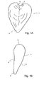
- Fig. 1 shows a breast cap 1 of slaughtered poultry.
- Fig. 1A is a rear view of the breast cap 1 and
- Fig. 1B is a side view.
- the breast cap 1 has a front 2, a neck side 3 and a back 4.
- the back 4 comprises the cutting plane along which the breast cap is cut loose from the remainder of the carcass of the slaughtered poultry.
- Fig. 1 clearly shows that the breast cap is substantially V-shaped.
- the top of the V shape is formed by the breast point 5 which is situated opposite the neck side 3.
- At least a part of the neck side 3 also has a V shape which is denoted in Fig. 1 by reference numeral 6.
- the neck side 3 of the breast cap 1 derives this V shape 6 from the wishbone.
- At least a part of the breastbone is present in the breast cap 1.
- Breast caps usually undergo further processing so that the breast meat which is present, for example in the form of fillets, is separated from the bones which are present in the breast cap, such as at least a part of the breastbone and in many cases also a part of the rib cage.
- the product carrier subsequently conveys the breast cap 1 along a track with one or more processing stations where the breast cap is processed.
- the processes can take place by hand, partly by hand or entirely automatically.
- Product carriers 50 which are suitable for breast caps 1 are often provided with a hook 51 (see Fig. 2 and Fig. 3 ).
- This hook 51 preferably acts on the breastbone in order to fix the breast cap relative to the product carrier.
- the product carrier 50 is further provided with a support surface 52 against which a breast cap 1 arranged on the product carrier 50 lies.
- the pin 57 ensures that the breast cap 1 sits securely in the hook 51.
- Fig. 3A shows the arrangement of a breast cap 1 on an alternative product carrier 50*
- Fig. 3B shows a breast cap 1 arranged on a product carrier 50* of this type.
- the hook 51 can have various shapes, as shown in Fig. 4A and Fig. 4B .
- the shape with the single tip 53 is common, but it is also possible to provide the hook 51 with a V shape 54.
- This V shape 54 can receive a tendon connected to the breastbone, thus allowing the breast cap 1 to be positioned well on the product carrier 50.
- Fig. 5 shows an example of an embodiment of a system comprising a device 10 not according to the invention.
- the system from Fig. 5 comprises a feed plate 11, a plurality of set-up units 20 and a plurality of product carriers 50.
- the product carriers 50 are conveyed in the direction of transportation T by a drive 55 along a track 56.
- the set-up units 20 are in this embodiment conveyed along a track 40, driven by the drive 41.
- Fig. 6 shows an application unit in greater detail.
- Fig. 6A shows the application unit in the receiving position
- Fig. 6B shows the application unit in the transfer position.
- Figures 11 , 12 and 13 also show an application unit.
- breast caps 1 are supplied by a supply device (not shown).
- the supply device can for example be a conveyor belt, a vibrating trough, a walking beam, a chute or a tray.
- An operator picks up a breast cap 1 from the supply device and lays it on the feed plate 11, with the back 4 directed upward and the neck side 3 turned away.
- the operator slides or lays the breast cap 1 in an application unit 20 via the feed plate 11.
- the actions performed by the operator are carried out by a robot or using other mechanical means.
- the application unit 20 comprises a holder 21, a neck support 22 and a pressing member 23.
- the holder 21 and the neck support 22 can each, independently of each other, pivot relative to the track 40 along which the set-up units 20 are movable.
- the pressing member 23 is slideable relative to the holder 21.
- the application unit comprises a holder tilting mechanism 24, a neck support tilting mechanism 25 and a pressing member movement mechanism 26 respectively.
- Each of these mechanisms is actuated by a cam track over which a cam roller 27, 28, 29 runs.
- the cam tracks are not shown in Fig. 5 .
- the components of the application unit 20 are mounted on a base part 36.
- the base parts 36 are in this example guided along a base part guide 37, so that the set-up units follow the track 40.
- the application member 23 has two pressing surfaces 38 which are set apart from each other and arranged to engage on either sides on the breast cap.
- the pressing surfaces 38 are arranged in such a way that they engage in proximity to the breast point.
- the pressing surfaces 38 are arranged substantially in an inverted V shape.
- the pressing member movement mechanism 26 is provided with a guide 39 for guiding the pressing member 23 along the holder 21.
- Fig. 7 shows an example of an embodiment of the method not according to the invention, suitable to be carried out using the system according to Fig. 5 .
- Fig. 7A shows a first step in the method.
- An operator has picked up a breast cap 1 from the supply device and lays it on the feed plate 11.
- the breast cap 1 is laid on the feed plate 11 in such a way that the back 4 is directed upward, the front 2 rests on the feed plate 11, the neck side 3 is directed away from the operator and the breast point 5 is directed towards the operator.
- the pitch between successive set-up units 20 is substantially equal to the pitch between successive product carriers 50.
- the set-up units 20 and the product carriers 50 move at the same speed in the direction of transportation T. This movement can be continuous or stepwise.
- the application unit 20 is in the receiving position.
- Fig. 7B shows a second step in the method.
- the application unit is still in the receiving position.
- the operator lays the breast cap 1 in the holder 21 of the application unit 20.
- the back 4 of the breast cap 1 is directed upward, the front 2 rests on the holder 11, the neck side 3 is directed away from the operator and the breast point 5 towards the operator.
- the operator lays the breast cap in the holder 21 in such a way that the neck side 3 of the breast cap lies against the neck support 22.
- Laying the breast cap 1 in the holder 21 of the application unit requires no or little force to be exerted by the operator. This is in contrast to the known manual manner of arranging breast caps on product carriers.
- the neck support 22 is embodied in the form of an upright plate.
- the surface where the neck side 3 of the breast cap 1 lies against the neck support 22 is fairly narrow.
- the neck support 22 By causing the neck support 22 to engage at the point of the V shape 6 of the neck side 3 of the breast cap 1, the neck side 3 of the breast cap 1 is positioned (preferably centred) in the holder 21. Further centring is achieved if the holder 21 has a V-shaped cross section. This can thus centre the breast cap 1 over its entire length in the holder 21.
- Causing the neck side 3 of the breast cap 1 to lie against the neck support 22 also ensures correct positioning of the breastbone of the breast cap 1 relative to the holder 21, both in the longitudinal direction and in the transverse direction of the breast cap 1.
- the neck support can be configured as a flat plate which, in use, extends substantially transversely to the breast cap. A neck support of this type positions the breast cap in its longitudinal direction but not in its transverse direction relative to the holder.
- the pressing member 23 is not yet in contact with the breast cap 1. It is possible to provide the pressing member with a lock which locks the position of the pressing member in this phase of the process relative to the holder 21.
- Fig. 7C shows a third step in the method.
- the holder 21 is tilted about the pivot shaft 30 from the receiving position (indicated by broken lines) to the transfer position (indicated by solid lines). This movement is actuated via the cam track 31, cam roller 27 and holder tilting mechanism 24.
- the neck support 22 remains in the same position as during the first and the second step of the method. For the sake of clarity, the neck support tilting mechanism is not shown in Fig. 7C .
- the pressing member 23 is still locked relative to the holder 21 during this step of the method. It is however also possible for any locking to be cancelled between the situation of Fig. 7B and that of Fig. 7C or for no lock to be present, so that the pressing member 23 already slides downward somewhat along the holder during the tilting of the holder 21 from the receiving position to the transfer position and comes to lie against the breast cap 1.
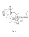
- the neck support 22 is shaped in such a way that the upper side of the neck support 22 lies at the same level as the top tip of the hook 51 of the product carrier 50 (see also Fig. 10 ).
- the breast cap at the top of the V shape 6 of the neck side 3, is guided by the neck support to a position relative to the product carrier 50 in which the breast cap 1 can be taken over by the product carrier 50.
- the breast cap enters a position in which the breast cap 1 can be transferred to the product carrier 50 in an effective manner. In the transfer position, the back 4 of the breast cap 1 lies against the support surface 52 of the product carrier 50.
- the neck support 22 has a shape which is adapted to the tilting movement of the holder 21. It will however be clear to the person skilled in the art that other shapes of the neck support are also possible.
- the neck support 22 is provided with a toothed surface. This offers the advantage that any tissue - such as skin, membranes or crop parts - present between the neck support 22 and the neck side 3 of the breast cap is pulled away during tilting of the holder 21, so that the neck side 3 comes to lie directly against the neck support 22.
- Fig. 7D shows a fourth step in the method.
- the neck support 22 is tilted away about the pivot shaft 33 by the neck support tilting mechanism 25.
- This mechanism 25 is actuated by the cam track 32 and cam roller 28.
- the breast cap 1 is now carried loosely by the hook 51 of the product carrier 50.
- the pin 57 is still retracted in the product carrier 50.
- Fig. 7E shows the fifth step in the method.
- the pressing member 23 is actively pressed downward.
- the pressing member 23 presses the breast cap securely onto the product carrier 50.
- the hook 51 preferably enters into engagement with a part of the breastbone or with the tissue in the immediate vicinity of the breastbone.
- the breast cap After the breast cap 1 has been pressed onto the product carrier 50, the breast cap sits securely on the product carrier 50 and the application unit can release the breast cap 1. For this purpose, the pressing member is raised again so that it is no longer engaging the breast cap 1.
- Pressing the pressing member down and raising it again can be carried out by a cam track having a profile suitable for this purpose. It is however also possible to cause the cam roller 29 to run in a track 34, and to move this track down and subsequently back up using an actuator.
- a pneumatic cylinder is for example suitable to serve as the actuator.
- Fig. 7F shows the final result of the method according to the invention: a breast cap 1 arranged on a product carrier 50.
- Fig. 8 is a further detailed view of the arrangement of the breast cap 1 on the product carrier 50. For the sake of clarity, Fig. 8 shows just a few components of the application unit 20.
- Fig. 8A shows that the neck support 22 brings the breast cap 1 to the product carrier 50.
- the broken line 7 indicates the top of the V shape 6 of the neck side 3.
- the neck support 22 acts on this top 7 and takes it above the top of the hook 51.
- Fig. 8B shows that the neck support 22 of the breast cap 1 is tilted away about the pivot shaft 33.
- the breast cap 1 continues to lie against the product carrier 50.
- the breast cap 1 is in this case held in position by the holder 21 (not shown in Fig. 8B ).
- Fig. 8C shows that the pressing member 23 presses the breast cap 1 downward relative to the product carrier 50. As a result, the breast cap 1 is pressed securely onto the hook 51. This is an action which requires a relatively high degree of force and caused injuries to operators in the case of the known method.
- Fig. 8D shows a breast cap 1 arranged on the product carrier 50.
- the pin 57 of the product carrier is extended in the direction of the breast cap 1. As a result, the breast cap is fixed even more securely on the product carrier 50.
- Fig. 9 shows the cam track 31 for actuating the tilting of the holder 21, the cam track 32 for actuating the tilting of the neck support 22 and the track 34 for activating the movement of the pressing member 23.
- the track 34 interacts with the pneumatic cylinder 35 which moves the track 34 downward and upward in the direction indicated by arrow P.
- Arrow T indicates the direction of transportation of the product carriers 50.
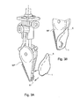
- Fig. 14 shows a second an embodiment of the device and method not according to the invention.
- separating line carriers 150 are used as product carriers.
- Whole carcasses 101 (which are preferably already made ready to cook and have optionally already been cooled) are arranged on these separating line carriers 150.
- the application unit 120 comprises a holder 121 which is adapted for receiving a whole carcass 101.
- the holder 121 is shaped in such a way that the carcass 101 is positioned in the holder 121 in an unambiguous manner.
- the holder 121 is provided with oblique sides 123 which ensure that the carcass 101 is longitudinally centred in the holder 121.
- the holder 121 is also provided with recesses 122 in which the wings 102 (or the parts of the wings 102 that are present) can be received. These recesses 122 thus help to position the carcass 101 relative to the holder 121.
- the holder 121 is mounted on a base part 136 which is movable along a base part guide 137.
- the holder 121 is pivotable relative to the base part 136 about the pivot shaft 130.
- Fig. 14 includes a feed plate 111 which is placed in such a way that an operator 112 or a robot can easily lay a carcass 101 in the holder 121 of an application unit 120 from the feed plate 111 when the holder 121 is in the receiving position.
- Fig. 14 shows various steps in the use of the second exemplary embodiment of the device according to the invention.
- Fig. 14A shows the first step in which a carcass 101 is laid on the feed plate 111, with the back on the plate and the breast facing upward.
- the neck side of the carcass part 101 points towards the application unit 120 and the legs point away from the application unit 120.
- the holder 121 of the application unit 120 is in the receiving position.
- the positions of the feed plate 111 and the holder 121 are adapted to each other in such a way that an operator 112 can easily slide the carcass 101 from the feed plate 111 into the holder (see arrow P1).
- An overhead transportation track comprising a plurality of product carriers in the form of separating line carriers 150 is provided.
- the application unit 120 can to move along a base part guide 137.
- a drive is provided for this purpose (not shown), for example in the same way as shown in combination with the first exemplary embodiment.
- the overhead transportation track comprising the separating line carriers 150 will move continuously at a substantially fixed speed.
- the separating line carriers can be moved intermittently.
- the carcass 101 can be transferred from the application unit 120 to the separating line carrier 150 while the separating line carriers 150 are stationary.
- Fig. 14 shows just a single application unit 120.
- an advantageous variant provides a plurality of set-up units which are preferably placed at a fixed mutual distance, which mutual distance corresponds to the mutual distance of the product carriers in which or on which the carcass 101 is arranged.
- Fig. 14B shows a following step.
- the carcass 101 to be suspended from the separating line carrier is now arranged in the holder 121 of the application unit.
- the wings 102 lie in the recesses 122 in the holder 121.
- the position of the carcass 101 relative to the longitudinal direction of the holder 121 is thus defined.
- the upright sides 123 of the holder 121 centre the carcass 101 in the holder 120.
- the separating line carrier 150 contains a lock 151 which has an open and a closed position. In the open position, it is possible to arrange a carcass 101 (or a carcass part such as a leg) in the separating line carrier 150 or to remove it from the separating line carrier 150. In the closed position, a carcass (or carcass part) which is present sits in the separating line carrier 150 in a locking manner.
- the lock is operated by an operating member which is arranged next to the overhead transportation track.
- the holder tilting mechanism 124 swivels the holder 121 from the receiving position ( Fig. 14B ) about the pivot shaft 130 to the transfer position ( Fig. 14C ), for example in the direction indicated by arrow P2 (see Fig. 14C ).
- the wings 102 of the carcass 101 come to lie against the edge of the recesses 122 under the force of gravity. This positions the carcass 101 relative to the holder 121.
- a number of components of the device according to the invention are omitted in Fig. 14C .
- the legs of the carcass 101 are brought into the leg slots 153 in the separating line carrier 150, for example by means of a guide (not shown) for the legs.
- the lock 151 is closed. This takes place by moving the lever 154 upward, for example in the direction indicated by arrow P5.
- the upward movement of the lever 154 can for example be achieved by a cam track which is arranged along the suspended transportation track and guides the lever.
- the carcass 101 is securely suspended from the separating line carrier 150.
- the holder 121 can now be swivelled back from the transfer position ( Fig. 14C ) to the receiving position (see Fig. 14D ), for example in the direction indicated by arrow P3.
- the application unit is then ready again to receive a following carcass 101. If necessary or desired, the application unit is for this purpose first brought back to a suitable position relative to the feed plate 111.
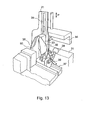
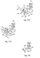
- Fig. 15 shows a variant of the device and method according to Fig. 14 .
- the carcass 101 is suspended not from a separating line carrier 150 but from a cooling line carrier 155.
- corresponding components are denoted by corresponding reference numerals.
- the variant of Fig. 15 and the variant of Fig. 14 work in corresponding ways.
- the variant of Fig. 15 is particularly suitable for use in the case of whole carcasses 101 which are made ready to cook.
- the legs are first arranged, as shown in Fig. 15C , in the wide parts of the leg slots 154 in the cooling line carrier 155.
- the carcass 101 falls downwards under the force of gravity in the direction indicated by arrows P4, as a result of which the legs enter the narrow part of the leg slots 154.
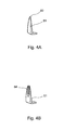
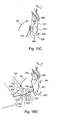
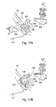
- Fig. 16 shows a first embodiment of the device and method according to the invention.
- This third embodiment corresponds to a high degree to the embodiment of Fig. 14 , insofar as in the embodiment according to Fig. 16 the application unit 120 has a holder 221 which is suitable for receiving a back half 105.
- corresponding components are denoted by corresponding reference numerals.
- Fig. 16A and Fig. 16B show the same steps for a back half 105 as Fig. 14A and Fig. 14B show for a whole carcass 101.
- Fig. 16C shows the transfer of the back half 105 from the application unit 120 comprising the holder 221 to the separating line carrier 150.
- the back half 105 cannot be released from the holder 221 by the tilting-away of the holder 221, such as is the case in Fig. 14C and Fig. 14D in the holder 121.
- the separating line carrier 150 is moved upward (arrow P6 in Fig. 16C ) relative to the holder 221, for example by causing the path of the overhead transportation track, from which the separating line carriers 150 are suspended, to run upward relative to the device according to the invention. This draws the back half 105 out of the holder 221.
- Fig. 17 shows a further embodiment of the device and method not according to the invention. Again, corresponding components are denoted by corresponding reference numerals. The functioning of this embodiment is broadly the same as that of the embodiments described hereinbefore.
- a front half 106 is arranged on a product carrier in the form of a carrying block 350.
- the carrying block 350 engages on the inside of the front half 106.
- the carrying block 350 is preferably connected to an overhead transportation track.
- the holder 321 is suitable for receiving a front half 106.
- the front half 106 is in this example arranged in the holder 321 with its neck side directed away from the carrying block 350 (arrow P1 in Fig. 17A ).
- the holder 321 is shaped in such a way that the front half 106 is well positioned in the holder and thus relative to the carrying block 350.
- Fig. 17A shows the front half 106 in the holder 321.
- Fig. 17B the holder is still in the receiving position.
- Fig. 17C shows that the holder 321 is tilted with the front half 106 therein.
- the holder 321 is for this purpose tilted about the pivot shaft 130.
- the tilting movement is imposed on the holder by the holder tilting mechanism 124, a part of which is shown in Fig. 17C .
- the front half 106 is substantially aligned with the carrying block 350.
- the front half 106 can be slid onto the carrying block. This is carried out by the pressing member 323 (see Fig. 17D ).
- the pressing member 323 is arranged below the feed plate 111.
- the pressing member 323 presses the holder 321 in the direction of the carrying block 350.
- the base part 136 comprises a guide block 340 which guides the holder in the direction of the carrying block 350 during this movement.
- the front half 106 is thus arranged on the carrying block 350.
- the holder 321 returns to its initial position, such as is shown in Fig. 17A .
- This can for example take place under the influence of gravity or with the aid of for example pneumatic cylinders or a cam track/cam roller structure.
- Fig. 17E shows a front half 106 arranged on the carrying block 350.
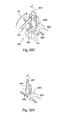
- Fig. 18 shows a second embodiment of the device and method according to the invention.
- the holder 421 is suitable for receiving two legs 107 or parts of legs.
- the holder 421 comprises four side plates 422 which, in pairs, can secure and can position a leg 107.
- the legs are arranged in a separating line carrier 150. It is however also possible to use a different type of product carrier, for example a cooling line carrier.
- Fig. 18 two legs are arranged in the product carrier at the same time.
- a person skilled in the art will understand that the embodiment according to Fig. 18 can easily be adapted for a different number of legs.
- Fig. 18A shows that an operator 112 places the legs 107 in the holder 421.
- Formed in the variant of Fig. 18 are recesses 423, the shape of which corresponds substantially to the shape of a leg 107. This helps to position the leg 107 relative to the holder 421. It is however also conceivable for such a recess 423 not to be provided. This results in a holder 421 which can be produced more inexpensively.
- the side plates 422 can be fixedly connected to the remainder of the holder 421, although a variant in which the side plates 422 can pivot relative to the remainder of the holder 421 is also conceivable.
- the pivot shaft of the side plates 422 then preferably runs substantially parallel to the longitudinal direction of a leg received in the holder.
- a torsion spring for example, then exerts a spring force on the side plates 422, pressing the side plates towards the remainder of the holder 421.
- the natural variation in leg thicknesses which occur can be effectively accommodated.
- Fig. 18B shows the tilting of the holder 422 from the application position to the transfer position.
- the holder 421 pivots about the pivot shaft 130.
- Fig. 18C the holder 421 has entered the transfer position.
- the tips of the legs 107 have arrived in the leg slots 153 in the separating line carrier 150, for example by means of a guide (not shown) for the legs.
- the lock 151 of the separating line carrier 150 is closed by raising the lever 154 in the direction indicated by arrow P5. This raising is for example achieved by guiding the separating line carrier 150 along a cam track (not shown).
- the person skilled in the art is familiar with this principle.
- the legs 107 can be released from the holder in various ways. It is possible to move the separating line carrier 150 upward in the direction of arrow P6 in Fig. 18D relative to the holder 421, for example by causing the path of the overhead transportation track, from which the separating line carriers are 150 suspended, to run upward relative to the device according to the invention. If, however, the holder is configured with pivotable side plates 422, the legs 107 are simply released from the holder 421 by tilting the holder 421 back to the receiving position.
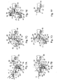
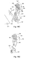
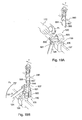
- Fig. 19 shows a third embodiment of the device and method according to the invention.
- carcass parts in this example legs 107 or parts thereof, are arranged in a marinating hook 550.
- this embodiment is also suitable for the arrangement of other carcass parts, for example wings or parts of wings, on hooks of this type.
- Fig. 19A shows how a leg 107 is arranged in the holder 521 by an operator 112. Just as in all other embodiments shown, this could also be done by, for example, a robot or another mechanical supply system rather than by a human operator.
- the holder 521 is designed for receiving one leg 107.
- Variants wherein a plurality of legs, leg parts, wings, wing parts or other carcass parts can be placed and/or positioned in the holder are conceivable.
- the holder 521 is provided with a curved plate 522 for securing the leg 107 in the holder 521. Also formed in the holder 521 is a recess, the shape of which corresponds substantially to the shape of a leg 107. This recess 523 helps to position the leg 107 in the holder 521.
- the curved plate 522 can be configured as one component, although it is possible for there to be two side plates as shown in Fig. 18 . It is in this case possible, just as in the variant of Fig. 18 , for these side plates to be fixedly connected to the remainder of the holder or for them to be pivotable as described in the discussion of Fig. 18 .
- Fig. 19A shows that the marinating hook has two legs 551. These legs are moveable, usually pivotable, relative to each other.
- Fig. 19A shows the marinating hook 550 in the open position, the legs 551 being at a distance from each other such that a carcass part to be carried, in this example a poultry leg 107, can be arranged between the legs 551.
- a spreader 560 is arranged between the legs 551 which spreads legs of the marinating hook 550 preferably counter to a spring force or other restoring force.
- Fig. 19B shows that the holder 521 is transferred from the receiving position ( Fig. 19A ) to the transfer position. In this embodiment too, this results from the tilting of the holder 521 about the pivot shaft 130 in the direction indicated by arrow P2.
- the free tip of the poultry leg 107 comes to lie between the legs 551 of the marinating hook 550.
- Fig. 19C shows that the marinating hook is closed. This results from the withdrawing of the spreader 560, for example in the direction indicated by arrow P8. A spring force or other restoring force ensures that the legs 551 move towards each other (arrow P7) and securely clamp the poultry leg 107.
- Fig. 20 shows a fourth embodiment of the device and method according to the invention.
- a carcass part for example a leg 107 or a part thereof or a wing or a part thereof, is fastened to the product carrier 650.
- the product carrier 650 is provided with a skewer 651 which is designed to pierce at least partly through the carcass part and thus to carry the carcass part.
- the product carrier 650 is placed on the guide rail 652 and can move relative to this rail in the direction of transportation T.
- just one product carrier 650 is shown on the rail 652, there are preferably a plurality of product carriers 650 which are at a fixed mutual distance.
- the product carriers 650 are moved by a drive comprising, for example, a chain 653.
- Fig. 20A shows the introduction of a carcass part, in this example a leg 107, in the holder 621 of the application unit 120.
- a human operator places the leg 107 in the holder, although this could also be carried out by a robot or another mechanical device.
- the holder 621 is in the receiving position.
- the holder 621 is provided with a recess 623, the shape of which corresponds substantially to the shape of the leg 107. This recess helps to position the leg 107 relative to the holder 621.
- Fig. 20B shows the transfer of the holder with the leg 621 from the receiving position to the transfer position (arrow P2).
- the holder 621 in this case pivots about the pivot shaft 130.
- the speed of the movement of the holder 621 from the receiving position to the transfer position is preferably so high that the mass inertia holds the leg 107 in the holder 621. It is also possible to make the recess 623 so deep that the leg 107 remains therein during the pivoting to the transfer position.
- the product carrier moves towards the holder, the holder remaining substantially in the receiving position.
- Fig. 20C shows the arrangement of the leg 107 on the product carrier 650.
- the holder 621 presses the leg 107 onto the skewer 651 of the product carrier 650.
- the leg 107 is positioned in such a way that the skewer 651 passes between the bones of the leg 107, so that no bone splinters are caused in the meat.
- the skewer 651 it is possible for the skewer 651 to have one or more barbs which ensure that the leg 107 remains suspended from the skewer 651 when the holder is tilted back from the transfer position to the receiving position.
- Fig. 20D shows a leg 107 arranged on the product carrier 650.
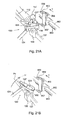
- Fig. 21 shows an fifth embodiment of the device and method according to the invention.
- Fig. 21A shows the introduction of a carcass part, in this example a leg 107, into the holder 921 of the application unit 120 (arrow P1).
- a human operator 112 places the leg 107 in the holder, although this could also be carried out by a robot or another mechanical device.
- the holder 921 is in the receiving position.
- Fig. 21B shows the transfer of the holder 921 with the leg 107 from the receiving position to the transfer position (arrow P2).
- the holder 921 in this case pivots about the pivot shaft 130.
- the product carrier 950 is provided with a receiving slot 956 and with a recess 957.
- the recess 957 is intended to receive a bone part 107* projecting from the wide side of the leg 107.
- the recess 957 can, if desired, also receive a different projecting part of a carcass part.
- Fig. 21C shows the holder 921 in the transfer position.
- the narrow part of the leg 107 is arranged in the receiving slot 956, whereas the projecting bone part 107* lies in the recess 957.
- the holder 921 has returned to the receiving position.
- the leg 107 is arranged in the product carrier 950, but is still slightly loose.
- guides 960 and 961 and the product carrier are provided with a cam roller 955.
- the leg guide 960 is located above the leg.
- the roller guide 961 is located below the roller 955.
- the roller guide 961 presses the roller 955, and thus the product carrier 950, upward.
- the leg guide 960 prevents the leg 107 arranged in the product carrier 950 from moving upwards too far with the product carrier.
- the projecting bone part 107* is pressed deeper into or even through the recess 957. This is shown in Fig. 21E .
- Fig. 22 shows a second example of an embodiment of a system comprising devices not according to the invention.
- the system of Fig. 22 comprises a number of set-up units 720 according to the invention.
- Each of the set-up units 720 comprises a holder 721 and a base part 736.
- the holder 721 is pivotable relative to the base part 736.
- the set-up units are moved by means of a drive (not shown) along a base part guide 737 in the direction of arrow T.
- the system of Fig. 22 comprises a supply station 710 with a feed plate 711.
- An operator places a carcass 701 on the feed plate 711 and slides the carcass over the feed plate 711 into the holder of a passing set-up unit 720. As it passes the supply station 710, the holder 721 is in the receiving position.
- the set-up units 720 are not directly coupled to one another. As a result, there does not have to be a fixed distance between successive set-up units.
- the distance between successive set-up units can also vary in accordance with the position of the set-up units in the system.
- the set-up units are brought to the application location 770 by their drive.
- the carcasses are arranged on the product carriers 750.
- the holders 721 of the set-up units are tilted to the transfer position in the supply station.
- the speed of the set-up units and the mutual distances thereof in the application location are adapted to the speed of the product carriers 750 and the mutual distances thereof.
- the speed of the set-up units at the application location will be higher than in the supply station.
- the mutual distance between successive set-up units will usually be greater in the application location than in the supply station.
- the variation in speed and mutual distances is for example achieved by a drive having one or more servomotors or having a mechanism comprising eccentric gear-wheels.
- the set-up units are returned to the supply station.
- the holders 721 are in this case tilted back to the receiving position so that when they arrive at the supply station, they can again receive a following carcass.
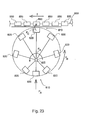
- Fig. 23 is a schematic view of an alternative embodiment of the system according to the invention.
- the system comprises a plurality of set-up units 820 which are connected to a central shaft 825.
- the set-up units can be connected to a disc which rotates about the central shaft 825 in the direction indicated by arrow P R . The distance between an individual set-up unit and the central shaft 825 varies during a revolution about the central shaft 825.
- carcasses or carcass parts which are supplied in the direction indicated by arrow PA are arranged on or in passing set-up units 820.
- the set-up units After the arrangement of a carcass part, the set-up units continue to rotate in the direction indicated by arrow PB.
- the distance from the set-up unit 820 to the central shaft 825 becomes greater and greater, as a result of which the mutual distance between successive set-up units 820 and the speed of the set-up units 820 increases.
- the increase in distance and speed is such that when a set-up unit arrives at the application location 870, the speed and the distance are adapted to the product carriers of the product line 855 which move in the direction of arrow T.
- the carcasses or carcass parts are arranged in or on the product carriers 850 in the direction indicated by arrow P C .
- the empty set-up units afterwards return to the supply station 810 where they are again provided with a carcass part.
- the distance between the set-up unit and the central shaft is again reduced, so that the speed and the mutual distance between successive product carriers is again suitable for placing carcasses or carcass parts in the set-up units.
- Fig. 23 shows a constructionally simple manner to create a variation in distance and speed of the product carriers.
- the carcass part can be placed in a holder of a set-up unit at a relatively low speed; this is desirable from the point of view of ergonomics.
- This system ensures that after the operator has arranged the carcass part, the carcasses or carcass parts are accelerated so that they can be arranged in a high-speed production line. In this way, it is possible to arrange products in a high-speed production line in an ergonomically expedient manner.
Landscapes
- Life Sciences & Earth Sciences (AREA)
- Engineering & Computer Science (AREA)
- Wood Science & Technology (AREA)
- Zoology (AREA)
- Food Science & Technology (AREA)
- Processing Of Meat And Fish (AREA)
Claims (13)
- Dispositif pour amener en position et agencer une partie de carcasse de volaille abattue sur ou dans un support de produit (150 ; 550 ; 650 ; 950), lequel dispositif comprend:au moins un ensemble d'une partie de base et d'un support (2521 ; 421 ; 521 ; 621 ; 921) mobile associé pour la partie de carcasse de volaille abattue avec des moyens de positionnement associés au support (221 ; 421 ; 521 ; 621 ; 921) pour la partie de carcasse, lequel support (221 ; 421 ; 521 ; 621 ; 921) est adapté pour recevoir une partie de carcasse destinée à être agencée sur ou dans un support de produit (150 ; 550 ; 650 ; 950),des moyens d'entraînement pour déplacer le support (221 ; 421 ; 521 ; 621 ; 921) par rapport à la partie de base associée au support (221 ; 421 ; 521 ; 621 ; 921) respectif entre une position de réception dans laquelle la partie de carcasse peut être reçue et une position de transfert dans laquelle la partie de carcasse est amenée dans une position par rapport au support de produit (150 ; 550 ; 650 ; 950) qui est appropriée pour transférer le support de produit (150 ; 550 ; 650 ; 950),caractérisé en ce que le support (221 ; 421 ; 521 ; 621 ; 921) est adapté pour recevoir au moins l'une parmi les parties suivantes : une moitié arrière, une patte ou une partie de patte, etdans lequel, dans la position de transfert, le support (221 ; 421 ; 521 ; 621 ; 921) positionne une patte ou une partie de patte de la partie de carcasse de sorte que le côté de hanche de la patte ou de la partie de patte est au-dessous du côté de genou de la patte ou de la partie de patte.
- Dispositif selon la revendication 1, dans lequel le dispositif comprend en outre un mécanisme d'application qui est adapté - dans la position de transfert du support (221 ; 421 ; 521 ; 621 ; 921) avec la partie de carcasse - pour agencer la partie de carcasse sur ou dans le support de produit (150; 550 ; 650 ; 950), et/ou
dans lequel le support (221 ; 421 ; 521 ; 621 ; 921) est mobile, par exemple pivotant, entre une position de réception sensiblement horizontale et une position de transfert sensiblement verticale, et/ou dans lequel le support (221 ; 421 ; 521 ; 621 ; 921) est adapté pour recevoir une partie de carcasse qui est prévue avec une marinade et/ou un enrobage, et/ou
dans lequel le support (221 ; 421 ; 521 ; 621 ; 921) est approprié pour recevoir deux pattes ou parties de pattes, et/ou
dans lequel le support (221 ; 421 ; 521 ; 621 ; 921) comprend un évidement (423 ; 523 ; 623), l'évidement (423 ; 523 ; 623) ayant une forme qui correspond sensiblement à la forme d'une patte. - Dispositif selon une ou plusieurs des revendications précédentes,
lequel dispositif est adapté pour interagir avec un support de produit (150 ; 550 ; 650 ; 950) mettant en prise une partie de patte de la partie de carcasse. - Dispositif selon la revendication 3, dans lequel le support mobile (221 ; 421 ; 521 ; 621 ; 921) comprend un évidement pour recevoir une partie d'aile qui est présente sur la partie de carcasse, dans lequel, de préférence l'évidement aide à positionner la partie de carcasse par rapport au support mobile (221 ; 421 ; 521 ; 621 ; 921).
- Dispositif selon la revendication 3, dans lequel le support mobile (221 ; 421 ; 521 ; 621 ; 921) comprend une partie en forme de manchon pour recevoir une partie de la partie de carcasse, laquelle partie en forme de manchon aide à positionner la partie de carcasse par rapport au support mobile (221 ; 421 ; 521 ; 621 ; 921).
- Système pour amener en position et agencer une partie de carcasse de volaille abattue sur ou dans un support de produit (150 ; 550 ; 650 ; 950), dans lequel le système comprend au moins un dispositif selon l'une des revendications précédentes, au moins l'ensemble de la partie de base et du support (221 ; 421 ; 521 ; 621 ; 921) du dispositif étant mobile le long d'un rail par des moyens d'entraînement associés, de sorte que, dans une station d'alimentation (810) le long du rail, une partie de carcasse peut être reçue dans le support (221 ; 421 ; 521 ; 621 ; 921) et, à un emplacement d'application en aval de la station d'alimentation (810), le support (221 ; 421 ; 521 ; 621 ; 921) est dans la position de transfert, dans lequel, à l'emplacement d'application - avec le support (221 ; 421 ; 521 ; 621 ; 921) qui a la partie de carcasse dans la position de transfert - la partie de carcasse peut être agencée sur le support de produit (150 ; 550 ; 650 ; 950).
- Système selon la revendication 6, dans lequel le système comprend une pluralité de dispositifs selon l'une des revendications 1 à 5, au moins les supports (221 ; 421 ; 521 ; 621 ; 921) des dispositifs étant espacés,
lequel système est de préférence adapté pour être combiné avec un dispositif de transport prévu avec une pluralité de supports de produit (150; 550 ; 650 ; 950) qui sont espacés et sont mobiles le long d'une trajectoire de transport associée, la distance mutuelle entre les supports (221 ; 421 ; 521 ; 621; 921) et la vitesse des supports (221 ; 421 ; 521 ; 621 ; 921) du dispositif étant adaptées à la distance entre les supports de produit (150 ; 550 ; 650 ; 950) et la vitesse des supports de produit (150; 550 ; 650 ; 950). - Système selon l'une des revendications 6 à 7,
dans lequel le système a un guide de partie de base le long duquel les parties de base des dispositifs selon l'une des revendications 1 à 4 sont mobiles, par exemple un rail en forme de boucle, par exemple dans le plan vertical, et/ou
dans lequel le système, à l'emplacement d'alimentation, a une plaque d'alimentation sur laquelle une partie de carcasse peut être placée et peut ensuite être coulissée à partir de la plaque d'alimentation de sorte que ladite partie de carcasse entre dans un support passant (221 ; 421 ; 521 ; 621 ; 921), par exemple dans lequel les supports (221 ; 421 ; 521 ; 621 ; 921) passent à un niveau plus bas que la plaque d'alimentation, par exemple de sorte que n'importe quel élément de pression présent sur le support (221 ; 421 ; 521 ; 621 ; 921) passe le long du fond de la plaque d'alimentation, et/ou
dans lequel un mécanisme suiveur de chemin de came est prévu pour chaque support (221 ; 421 ; 521 ; 621 ; 921) et le système est prévu avec un chemin de came approprié pour produire le mouvement du support (221 ; 421 ; 521 ; 621 ; 921) . - Système selon la revendication 6, dans lequel les dispositifs selon l'une des revendications 1 à 5 sont indépendamment mobiles les uns des autres le long du chemin, ou bien
dans lequel la distance mutuelle entre les dispositifs selon l'une des revendications 1 à 5 est variable, ou bien
dans lequel l'entraînement pour déplacer les dispositifs selon l'une des revendications 1 à 5 le long du chemin est adapté pour permettre ou mettre en oeuvre une variation de la vitesse des dispositifs respectifs. - Ensemble comprenant un dispositif ou un système selon les une ou plusieurs des revendications ainsi qu'un dispositif de transport prévu avec un ou plusieurs supports de produit (150 ; 550 ; 650 ; 950) sur lequel (lesquels) une partie de carcasse peut être agencée en utilisant le dispositif, dans lequel l'ensemble comprend en outre de préférence un dispositif d'alimentation mécanique pour amener les carcasses ou les parties de carcasse à un dispositif ou système selon les une ou plusieurs des revendications 1 à 5.
- Ensemble selon la revendication 10,
dans lequel les supports de produit (150 ; 550 ; 650 ; 950) sont des supports de ligne de refroidissement ou des supports de ligne de séparation, ou bien
dans lequel les supports de produit (150 ; 550 ; 650 ; 950) sont appropriés pour être utilisés dans un système pour faire mariner et/ou enrober les carcasses ou parties de carcasse de volaille abattue, ou bien
dans lequel les supports de produit (150 ; 550; 650 ; 950) sont prévues avec une broche (651) pour percer au moins partiellement à travers la partie de carcasse à transporter afin de fixer la partie de carcasse respective sur le support de produit (150 ; 550 ; 650 ; 950). - Procédé pour agencer une partie de carcasse de volaille abattue sur un support de produit (150 ; 550 ; 650 ; 950), laquelle partie de carcasse est au moins l'une parmi les parties suivantes : une moitié arrière, une patte ou une partie de patte, en utilisant un dispositif pour amener en position et agencer une partie de carcasse de volaille abattue sur ou dans un support de produit (150 ; 550 ; 650 ; 950), lequel dispositif comprend :au moins un ensemble d'une partie de base et d'un support (221 ; 421 ; 521 ; 621 ; 921) mobile associé pour la partie de carcasse de volaille abattue avec des moyens de positionnement associés au support (221 ; 421 ; 521 ; 621 ; 921) pour la partie de carcasse, lequel support (221 ; 421 ; 521 ; 621 ; 921) est adapté pour recevoir une partie de carcasse destinée à être agencée sur ou dans un support de produit (150 ; 550 ; 650 ; 950),des moyens d'entraînement pour déplacer le support (221 ; 421 ; 521 ; 621 ; 921) par rapport à la partie de base associée au support (221 ; 421 ; 521 ; 621 ; 921) respectif entre une position de réception dans laquelle la partie de carcasse peut être reçue et une position de transfert dans laquelle la partie de carcasse est amenée dans une position par rapport au support de produit (150 ; 550 ; 650 ; 950) qui est approprié pour le transfert sur le support de produit (150; 550 ; 650 ; 950),dans lequel le support (221 ; 421 ; 521 ; 621 ; 921) est adapté pour recevoir au moins l'une parmi les parties suivantes : une moitié arrière, une patte ou une partie de patte, ou un système pour amener en position et agencer une partie de carcasse de volaille abattue sur ou dans un support de produit (150 ; 550 ; 650 ; 950), dans lequel le système comprend au moins ledit dispositif, au moins l'ensemble de la partie de base et du support (221 ; 421 ; 521 ; 621 ; 921) du dispositif étant mobile le long d'un chemin par des moyens d'entraînement, de sorte que, dans une station d'alimentation (810) le long du chemin, une partie de carcasse peut être reçue dans le support (221 ; 421 ; 521 ; 621 ; 921) et à un emplacement d'application en aval de la station d'alimentation (810), le support (221 ; 421 ; 521 ; 621 ; 921) est dans la position de transfert, dans lequel, à l'emplacement d' application - avec le support (221 ; 421 ; 521 ; 621 ; 921) qui a la partie de carcasse dans la position de transfert - la partie de carcasse peut être agencée sur le support de produit (150 ; 550 ; 650 ; 950).
- Procédé pour agencer une partie de carcasse de volaille abattue sur un support de produit (150 ; 550 ; 650 ; 950), lequel procédé comprend les étapes consistant à :agencer une partie de carcasse de volaille abattue dans un support (221 ; 421 ; 521 ; 621 ; 921) d'un dispositif, pour amener en position et agencer une partie de carcasse de volaille abattue sur ou dans un support de produit (150 ; 50 ; 650 ; 950), lequel dispositif comprend :au moins un ensemble d'une partie de base et d'un support (221 ; 421 ; 521 ; 621 ; 921) mobile associé pour la partie de carcasse de volaille abattue avec des moyens de positionnement associés au support (221 ; 421 ; 521 ; 621 ; 921) pour la partie de carcasse, lequel support (221 ; 421 ; 521 ; 621 ; 921) est adapté pour recevoir une partie de carcasse destinée à être agencée sur ou dans un support de produit (150 ; 550 ; 650 ; 950),des moyens d'entraînement pour déplacer le support (221 ; 421 ; 521 ; 621 ; 921) par rapport à la partie de base associée avec le support (221 ; 421 ; 521 ; 621 ; 921) respectif entre une position de réception dans laquelle la partie de carcasse peut être reçue et une position de transfert dans laquelle la partie de carcasse est amenée dans une position par rapport au support de produit (150 ; 550 ; 650 ; 950) qui est appropriée pour le transfert au support de produit (150 ; 550 ; 650 ; 950),dans lequel le support (221 ; 421 ; 521 ; 621 ; 921) est adapté pour recevoir au moins l'une des parties suivante une moitié arrière, une patte ou une partie de patte,le support (221 ; 421 ; 521 ; 621 ; 921) étant dans la position de réception,positionner la partie de carcasse dans le support (221 ; 421 ; 521 ; 621 ; 921) au moyen des moyens de positionnement avec le support (221 ; 421 ; 521 ; 621 ; 921),déplacer le support (221 ; 421 ; 521 ; 621 ; 921) de la position de réception à la position de transfert, ettransférer la partie de carcasse du support (221 ; 421 ; 521 ; 621 ; 921) au support de produit (150 ; 550 ; 650 ; 950) de sorte que la partie de carcasse est agencée sur ou dans le support de produit (150 ; 550 ; 650 ; 950),dans lequel la partie de carcasse est au moins l'une parmi les parties suivantes : une moitié arrière, une patte ou une partie de patte.
Applications Claiming Priority (3)
| Application Number | Priority Date | Filing Date | Title |
|---|---|---|---|
| NL1034027A NL1034027C2 (nl) | 2007-06-22 | 2007-06-22 | Inrichting en werkwijze voor het in positie brengen en het aanbrengen van een borstkap van een geslacht gevogelte op een productdrager. |
| NL2001241A NL2001241C1 (nl) | 2007-06-22 | 2008-01-31 | Inrichting en werkwijze voor het in positie brengen en het aanbrengen van karkas of karkasdeel van geslacht gevogelte op of aan een productdrager. |
| EP08782788A EP2162007B1 (fr) | 2007-06-22 | 2008-06-23 | Dispositif et procédé pour amener en position et agencer une carcasse ou une partie de carcasse d'une volaille abattue sur un support de produit ou dans celui-ci |
Related Parent Applications (2)
| Application Number | Title | Priority Date | Filing Date |
|---|---|---|---|
| EP08782788A Division EP2162007B1 (fr) | 2007-06-22 | 2008-06-23 | Dispositif et procédé pour amener en position et agencer une carcasse ou une partie de carcasse d'une volaille abattue sur un support de produit ou dans celui-ci |
| EP08782788.7 Division | 2008-06-23 |
Publications (3)
| Publication Number | Publication Date |
|---|---|
| EP2389812A2 EP2389812A2 (fr) | 2011-11-30 |
| EP2389812A3 EP2389812A3 (fr) | 2013-11-06 |
| EP2389812B1 true EP2389812B1 (fr) | 2015-08-12 |
Family
ID=38829634
Family Applications (2)
| Application Number | Title | Priority Date | Filing Date |
|---|---|---|---|
| EP08782788A Active EP2162007B1 (fr) | 2007-06-22 | 2008-06-23 | Dispositif et procédé pour amener en position et agencer une carcasse ou une partie de carcasse d'une volaille abattue sur un support de produit ou dans celui-ci |
| EP11178825.3A Active EP2389812B1 (fr) | 2007-06-22 | 2008-06-23 | Dispositif et procédé pour amener en position et agencer une partie de carcasse d'une volaille abattue sur un support de produit ou dans celui-ci |
Family Applications Before (1)
| Application Number | Title | Priority Date | Filing Date |
|---|---|---|---|
| EP08782788A Active EP2162007B1 (fr) | 2007-06-22 | 2008-06-23 | Dispositif et procédé pour amener en position et agencer une carcasse ou une partie de carcasse d'une volaille abattue sur un support de produit ou dans celui-ci |
Country Status (9)
| Country | Link |
|---|---|
| US (1) | US8540556B2 (fr) |
| EP (2) | EP2162007B1 (fr) |
| JP (3) | JP5371970B2 (fr) |
| AT (1) | ATE548918T1 (fr) |
| BR (2) | BRPI0823510B1 (fr) |
| DK (2) | DK2389812T3 (fr) |
| ES (2) | ES2551236T3 (fr) |
| NL (2) | NL1034027C2 (fr) |
| WO (1) | WO2009002153A1 (fr) |
Families Citing this family (24)
| Publication number | Priority date | Publication date | Assignee | Title |
|---|---|---|---|---|
| US9262490B2 (en) | 2004-08-12 | 2016-02-16 | Oracle International Corporation | Adaptively routing transactions to servers |
| NL1034027C2 (nl) | 2007-06-22 | 2008-12-23 | Stork Pmt | Inrichting en werkwijze voor het in positie brengen en het aanbrengen van een borstkap van een geslacht gevogelte op een productdrager. |
| PL2512255T3 (pl) | 2009-12-17 | 2024-07-22 | Marel Red Meat B.V. | System i sposób przetwarzania ubitych zwierząt lub ich części |
| BR112012023992B1 (pt) | 2010-03-26 | 2018-03-13 | Linco Food Systems A/S | Método e aparelho para suspender aves domésticas a serem abatidas. |
| NL2007492C2 (en) * | 2011-09-28 | 2013-04-02 | Marel Stork Poultry Proc Bv | Carrier for supporting a carcass part of slaughtered poultry. |
| NL2007888C2 (en) † | 2011-11-29 | 2013-05-30 | Meyn Food Proc Technology Bv | Deboner for poultry parts, such as thighs or drumsticks. |
| US9081120B2 (en) * | 2012-01-17 | 2015-07-14 | Ion Geophysical Corporation | Apparatus and method for low-tension retrieval of instrumented marine cables |
| US9066525B2 (en) * | 2012-07-12 | 2015-06-30 | Marel Meat Processing Inc. | Shoulder positioning conveyor |
| US8838535B2 (en) | 2012-10-05 | 2014-09-16 | Oracle International Corporation | Providing services across systems that manage distributed replicas |
| US8535124B1 (en) | 2012-10-17 | 2013-09-17 | Remington Holdings Llc | Poultry tender tendon clipper |
| WO2014174121A1 (fr) | 2013-04-26 | 2014-10-30 | Marel Meat Processing Inc. | Système permettant de traiter des parties de carcasses |
| BR112016017408B1 (pt) | 2014-02-07 | 2021-06-01 | Linco Food Systems A/S | Dispositivo de posicionamento para posicionar pernas de aves de criação conduzidas em fila única na direção de condução ao longo de uma seção de condutor e método que compreende o dito posicionamento para remover a carne da coxa das pernas de aves de criação |
| JP5959611B2 (ja) * | 2014-12-19 | 2016-08-02 | 株式会社大一商会 | 遊技機 |
| US9842148B2 (en) | 2015-05-05 | 2017-12-12 | Oracle International Corporation | Method for failure-resilient data placement in a distributed query processing system |
| US10474653B2 (en) | 2016-09-30 | 2019-11-12 | Oracle International Corporation | Flexible in-memory column store placement |
| US9901103B1 (en) * | 2016-11-10 | 2018-02-27 | Tecsal S.P.A. | Automatic machine for removing the bacon hanging hook |
| NL2019428B1 (en) | 2017-08-18 | 2019-02-25 | Marel Stork Poultry Proc Bv | Carrier for holding poultry carcasses |
| US11954117B2 (en) | 2017-09-29 | 2024-04-09 | Oracle International Corporation | Routing requests in shared-storage database systems |
| NL2020679B1 (en) * | 2018-03-28 | 2019-10-07 | Meyn Food Processing Tech Bv | System for placement of a supply of poultry front halves in an ordered sequence in a processing line |
| PL3689148T3 (pl) | 2019-01-29 | 2022-07-04 | Nordischer Maschinenbau Rud. Baader Gmbh + Co. Kg | Urządzenie trzymające i sposób trzymania wypatroszonego korpusu drobiowego lub jego części podczas obróbki w urządzeniu do obróbki wypatroszonych korpusów drobiowych lub ich części |
| DE102020117866A1 (de) * | 2020-07-07 | 2022-01-13 | Nordischer Maschinenbau Rud. Baader Gmbh + Co. Kg | Vorrichtung und Verfahren zur automatischen Verarbeitung von entweideten Geflügelkörpern oder Teilen davon |
| US20230404089A1 (en) * | 2020-10-19 | 2023-12-21 | Baader Poultry Holding Gmbh | Apparatus and method for processing poultry carcasses |
| CN118511198A (zh) * | 2021-12-17 | 2024-08-16 | 北欧机械制造鲁道夫巴德尔有限及两合公司 | 用于确定弯曲制品的位置和用于装载这种制品的方法和设备 |
| WO2024155874A1 (fr) * | 2023-01-19 | 2024-07-25 | Georgia Tech Research Corporation | Dispositif de réaccrochage pour traitement de volaille |
Citations (14)
| Publication number | Priority date | Publication date | Assignee | Title |
|---|---|---|---|---|
| DE3048342A1 (de) | 1980-12-20 | 1982-07-29 | Gebr. Stolle GmbH u. Co KG, 2849 Visbek | Verfahren und vorrichtung zum uebergeben von schlachtgefluegel an die schlachthaken einer transportbahn |
| NL8201782A (nl) | 1982-04-29 | 1983-11-16 | Stolle Gmbh & Co Kg Geb | Werkwijze en inrichting voor het overgeven van slachtpluimvee aan de slachthaken van een transportbaan. |
| EP0109708B1 (fr) | 1982-11-18 | 1986-07-23 | Stork Pmt B.V. | Procédé et appareil de découpage de volailles abattues en partie avant et partie arrière |
| US4658476A (en) | 1983-11-28 | 1987-04-21 | Den Brink Hendrikus G Van | Device for conveying chickens to a slaughtering plant |
| US5108345A (en) | 1991-03-25 | 1992-04-28 | Grover S. Harben, III | Apparatus and method for loading live fowl onto a conveyor |
| EP0459580B1 (fr) | 1990-05-31 | 1995-08-23 | Stork Pmt B.V. | Procédé et dispositif pour séparer des pattes d'une partie du corps de volailles abattues |
| EP0819382A1 (fr) | 1996-07-16 | 1998-01-21 | Stork Pmt B.V. | Dispositif pour recevoir et transférer des animaux abattus ou parties de ceux-ci |
| US5782056A (en) | 1994-01-18 | 1998-07-21 | Delaware Capital Formation, Inc. | Packaging apparatus for removing a product from a continuously moving conveyor and sealing said product in a bag with a closure |
| EP0853884A1 (fr) | 1997-01-21 | 1998-07-22 | Nordischer Maschinenbau Rud. Baader Gmbh + Co Kg | Dispositif pour le traitement du corps de volailles abattues |
| US6716096B2 (en) | 2000-01-18 | 2004-04-06 | Hill & Sons, Inc. | Poultry feces removal apparatuses and methods |
| EP1276382B1 (fr) | 2000-04-19 | 2007-01-24 | Linco Food Systems A/S | Procede et appareil de suspension d'animaux d'abattage, notamment de poulets |
| WO2009002153A1 (fr) | 2007-06-22 | 2008-12-31 | Stork Pmt B.V. | Dispositif et procédé pour amener en position et agencer une carcasse ou une partie de carcasse d'une volaille abattue sur un support de produit ou dans celui-ci |
| EP2263468A2 (fr) | 1999-01-15 | 2010-12-22 | Marel Stork Poultry Processing B.V. | Dispositif pour transporter des volailles étourdies ou tuées |
| EP2332419A2 (fr) | 2005-12-09 | 2011-06-15 | Marel Stork Poultry Processing B.V. | Procédé et dispositif de traitement d'une pièce de carcasse de volaille abattue |
Family Cites Families (21)
| Publication number | Priority date | Publication date | Assignee | Title |
|---|---|---|---|---|
| US2560067A (en) * | 1949-06-25 | 1951-07-10 | Leland J Bell | Device for folding the legs of an eviscerated bird |
| US2785437A (en) * | 1955-05-23 | 1957-03-19 | Robert E Standley | Wing joint breaker for poultry |
| US2958092A (en) * | 1958-05-12 | 1960-11-01 | Charles L Curtis | Automatic head dropper for poultry |
| US3979793A (en) * | 1974-04-12 | 1976-09-14 | Barker International, Inc. | Poultry eviscerating apparatus |
| NL7905612A (nl) * | 1979-07-19 | 1981-01-21 | Meyn Pieter | Inrichting voor het afknijpen van de nek van gevogelte. |
| US4283813A (en) * | 1979-12-03 | 1981-08-18 | Stork Gamco, Inc. | Poultry inspection apparatus and method |
| NL8202180A (nl) * | 1982-05-28 | 1983-12-16 | Stork Pmt | Inrichting voor het overbrengen van geslacht gevogelte. |
| US4513476A (en) * | 1983-03-21 | 1985-04-30 | Cagle's, Inc. | Apparatus for processing poultry |
| NL8601921A (nl) | 1986-07-24 | 1988-02-16 | Stork Pmt | Opzetsteun. |
| US4873746A (en) * | 1988-01-25 | 1989-10-17 | Simon-Johnson Company | Method and apparatus for removing breast meat from poultry carcass |
| US4899421A (en) * | 1988-08-08 | 1990-02-13 | Stork-Gamco, Inc. | Method and apparatus for removing fecal matter in poultry |
| US5340351A (en) * | 1993-01-21 | 1994-08-23 | Systemate Holland B.V. | Poultry conveyor line transfer system |
| NL1000935C2 (nl) * | 1995-08-04 | 1997-02-06 | Stork Pmt | Inrichting en werkwijze voor het bewerken van een slachtdier. |
| US6033286A (en) * | 1996-02-28 | 2000-03-07 | Langlinais; Glenn D. | Toy conveyor oven |
| US5913720A (en) * | 1997-01-21 | 1999-06-22 | Johnson Food Equipment, Inc. | Method and apparatus for preparing an access slit in the neck of a poultry carcass |
| US6190250B1 (en) * | 1998-02-20 | 2001-02-20 | Stork Gamco Incorporated | Method and apparatus for performing processing operations on a slaughtered animal or part thereof |
| NL1014845C1 (nl) | 1999-06-11 | 2000-12-12 | Stork Pmt | Inrichting voor het verwerken van een slachtproduct. |
| NL1012463C2 (nl) * | 1999-06-29 | 2001-01-02 | Meyn Food Proc Technology Bv | Inrichting voor het lossnijden van de aars van geslacht gevogelte. |
| DK1665935T3 (da) * | 2004-12-06 | 2007-12-03 | Rico Research Bv | Anording til bedövelse af fjerkræ |
| JP4972083B2 (ja) * | 2005-04-05 | 2012-07-11 | ドナルドソン カンパニー,インコーポレイティド | フィルタエレメントの配置構成、ろ過方法、組立方法 |
| NL2000159C2 (nl) * | 2006-07-24 | 2008-01-25 | Stork Pmt | Inrichting, werkwijze en productielijn voor het conditioneren van geslacht pluimvee. |
-
2007
- 2007-06-22 NL NL1034027A patent/NL1034027C2/nl not_active IP Right Cessation
-
2008
- 2008-01-31 NL NL2001241A patent/NL2001241C1/nl not_active IP Right Cessation
- 2008-06-23 AT AT08782788T patent/ATE548918T1/de active
- 2008-06-23 EP EP08782788A patent/EP2162007B1/fr active Active
- 2008-06-23 WO PCT/NL2008/000159 patent/WO2009002153A1/fr active Application Filing
- 2008-06-23 US US12/665,667 patent/US8540556B2/en active Active
- 2008-06-23 DK DK11178825.3T patent/DK2389812T3/en active
- 2008-06-23 EP EP11178825.3A patent/EP2389812B1/fr active Active
- 2008-06-23 BR BRPI0823510-4A patent/BRPI0823510B1/pt active IP Right Grant
- 2008-06-23 BR BRPI0812595-3A patent/BRPI0812595B1/pt active IP Right Grant
- 2008-06-23 DK DK08782788.7T patent/DK2162007T3/da active
- 2008-06-23 ES ES11178825.3T patent/ES2551236T3/es active Active
- 2008-06-23 JP JP2010513136A patent/JP5371970B2/ja active Active
- 2008-06-23 ES ES08782788T patent/ES2384358T3/es active Active
-
2013
- 2013-04-24 JP JP2013091098A patent/JP2013162792A/ja active Pending
-
2015
- 2015-01-28 JP JP2015014075A patent/JP6049102B2/ja active Active
Patent Citations (17)
| Publication number | Priority date | Publication date | Assignee | Title |
|---|---|---|---|---|
| DE3048342A1 (de) | 1980-12-20 | 1982-07-29 | Gebr. Stolle GmbH u. Co KG, 2849 Visbek | Verfahren und vorrichtung zum uebergeben von schlachtgefluegel an die schlachthaken einer transportbahn |
| NL8201782A (nl) | 1982-04-29 | 1983-11-16 | Stolle Gmbh & Co Kg Geb | Werkwijze en inrichting voor het overgeven van slachtpluimvee aan de slachthaken van een transportbaan. |
| EP0109708B1 (fr) | 1982-11-18 | 1986-07-23 | Stork Pmt B.V. | Procédé et appareil de découpage de volailles abattues en partie avant et partie arrière |
| US4658476A (en) | 1983-11-28 | 1987-04-21 | Den Brink Hendrikus G Van | Device for conveying chickens to a slaughtering plant |
| EP0459580B1 (fr) | 1990-05-31 | 1995-08-23 | Stork Pmt B.V. | Procédé et dispositif pour séparer des pattes d'une partie du corps de volailles abattues |
| US5108345A (en) | 1991-03-25 | 1992-04-28 | Grover S. Harben, III | Apparatus and method for loading live fowl onto a conveyor |
| US5782056A (en) | 1994-01-18 | 1998-07-21 | Delaware Capital Formation, Inc. | Packaging apparatus for removing a product from a continuously moving conveyor and sealing said product in a bag with a closure |
| EP1138205A2 (fr) | 1996-07-16 | 2001-10-04 | Stork Pmt B.V. | Dispositif pour recevoir et transférer des animaux abattus ou parties de ceux-ci |
| EP0819382A1 (fr) | 1996-07-16 | 1998-01-21 | Stork Pmt B.V. | Dispositif pour recevoir et transférer des animaux abattus ou parties de ceux-ci |
| EP0853884A1 (fr) | 1997-01-21 | 1998-07-22 | Nordischer Maschinenbau Rud. Baader Gmbh + Co Kg | Dispositif pour le traitement du corps de volailles abattues |
| EP2263468A2 (fr) | 1999-01-15 | 2010-12-22 | Marel Stork Poultry Processing B.V. | Dispositif pour transporter des volailles étourdies ou tuées |
| US6716096B2 (en) | 2000-01-18 | 2004-04-06 | Hill & Sons, Inc. | Poultry feces removal apparatuses and methods |
| EP1276382B1 (fr) | 2000-04-19 | 2007-01-24 | Linco Food Systems A/S | Procede et appareil de suspension d'animaux d'abattage, notamment de poulets |
| EP2332419A2 (fr) | 2005-12-09 | 2011-06-15 | Marel Stork Poultry Processing B.V. | Procédé et dispositif de traitement d'une pièce de carcasse de volaille abattue |
| WO2009002153A1 (fr) | 2007-06-22 | 2008-12-31 | Stork Pmt B.V. | Dispositif et procédé pour amener en position et agencer une carcasse ou une partie de carcasse d'une volaille abattue sur un support de produit ou dans celui-ci |
| EP2389812A2 (fr) | 2007-06-22 | 2011-11-30 | Marel Stork Poultry Processing B.V. | Dispositif et procédé pour amener en position et agencer une carcasse ou une partie de carcasse d'une volaille abattue sur un support de produit ou dans celui-ci |
| EP2162007B1 (fr) | 2007-06-22 | 2012-03-14 | Marel Stork Poultry Processing B.V. | Dispositif et procédé pour amener en position et agencer une carcasse ou une partie de carcasse d'une volaille abattue sur un support de produit ou dans celui-ci |
Non-Patent Citations (13)
| Title |
|---|
| "?Weigh Transfer In-line 530, Proflex Cut-up", FA. LDS AQUITAINE IN FRANKREICH, 22 June 2005 (2005-06-22) |
| "?Weigh Transfer In-line 530, Proflex Cut-up", LIEFERLISTE FÜR SYSTEME DES TYPS, 2008 |
| "?Weigh Transfer In-line 530, Proflex Cut-up", LIEFERUNG AN DIE FA. LDC AQUITAINE IN FRANKREICH, 23 May 2005 (2005-05-23) |
| "?Weigh Transfer In-line 530, Proflex Cut-up", MASCHINENNUMMER A17 5300 649 001 AN DIE FA. ETS SECOUE IN FRANKREICH, 25 April 2002 (2002-04-25) |
| "?Weigh Transfer In-line 530, Proflex Cut-up", MASCHINENNUMMER A17 5300 649 001 FÜR DIE LIEFERUNG AN DIE FA. ETS SECOUE IN FRANKREICH, 25 April 2002 (2002-04-25) |
| "Funktionsweise des Systems vom Typ ACM- MX gemäß Anlage V9 zeigt", DVD , EINREICHUNG ERFOLGT PER KURIER, Retrieved from the Internet <URL:https:llwww.youtube.comlwatch?v=q-BCHJwPek8> |
| "Technische Zeichnung ?Weigh Transfer In-line 530, Proflex Cut-up", MASCHINENNUMMER A17 5300 649 003, 20 May 2005 (2005-05-20) |
| "Video ?Linco 530 In-line Weigh Transfer, Proflex Cut-up", DVD , EINREICHUNG ERFOLGT PER KURIER |
| ?FLEXIBEL MODULAIR OPDEELSYSTEEM ACM- MX VON STORK, 1 November 1997 (1997-11-01) |
| ?WEIGH TRANSFER- LINCO 530 IN-LINE, PROFLEX CUT-UP, 15 September 2003 (2003-09-15) |
| ENGLISCHE ÜBERSETZUNG DER D1 (INCLUSIVE ÜBERSETZER-ZERTIFIKAT |
| EUROPÄISCHE R RECHERCHENBERICHT MIT STELLUNGNAHME (ZUM STREITPATENT |
| TECHNISCHE ZEICHNUNG ?WEIGHT TRANSFER IN-LINE 530, PROFLEX CUT-UP'' MIT DER MASCHINENNUMMER A17 5300 649 001, 13 November 2001 (2001-11-13) |
Also Published As
| Publication number | Publication date |
|---|---|
| BRPI0812595B1 (pt) | 2017-12-19 |
| EP2162007B1 (fr) | 2012-03-14 |
| ES2551236T3 (es) | 2015-11-17 |
| EP2162007A1 (fr) | 2010-03-17 |
| US8540556B2 (en) | 2013-09-24 |
| JP5371970B2 (ja) | 2013-12-18 |
| JP6049102B2 (ja) | 2016-12-21 |
| NL1034027C2 (nl) | 2008-12-23 |
| US20100323599A1 (en) | 2010-12-23 |
| BRPI0823510A2 (pt) | 2013-12-17 |
| DK2162007T3 (da) | 2012-07-02 |
| NL2001241C1 (nl) | 2008-12-23 |
| ATE548918T1 (de) | 2012-03-15 |
| EP2389812A2 (fr) | 2011-11-30 |
| BRPI0812595A2 (pt) | 2012-12-25 |
| BRPI0823510B1 (pt) | 2018-08-07 |
| JP2013162792A (ja) | 2013-08-22 |
| JP2010530751A (ja) | 2010-09-16 |
| ES2384358T3 (es) | 2012-07-04 |
| JP2015077151A (ja) | 2015-04-23 |
| WO2009002153A1 (fr) | 2008-12-31 |
| EP2389812A3 (fr) | 2013-11-06 |
| DK2389812T3 (en) | 2015-11-23 |
Similar Documents
| Publication | Publication Date | Title |
|---|---|---|
| EP2389812B1 (fr) | Dispositif et procédé pour amener en position et agencer une partie de carcasse d'une volaille abattue sur un support de produit ou dans celui-ci | |
| JP6903085B2 (ja) | 豚や牛や羊や山羊といった屠殺された動物の屠殺体の一部を処理するためのシステムおよび方法、ならびに屠殺された豚の脚を運搬するための搬送デバイス | |
| EP2353396B1 (fr) | Procédé et dispositif de traitement d'une pièce de carcasse de volaille abattue | |
| EP1654932B1 (fr) | Machine de filetage de volailles | |
| KR101861466B1 (ko) | 컨베이어 섹션을 따라 이송하는 방향으로 단일 파일로 이송된 가금류 다리를 위치잡기 위한 위치 장치 및 가금류 다리로부터 넓적다리 고기를 분리하기 위하여 위치잡기를 포함하는 방법 | |
| KR20080074978A (ko) | 발골 장치 | |
| CS274484B2 (en) | Equipment for machine separation of wings from poultry body | |
| JP6719547B2 (ja) | 屠体の肩肉から肩甲骨を自動的に緩める又は除去するためのシステム及び方法 | |
| EP2760289A1 (fr) | Support de pièce de carcasse de volaille abattue | |
| CN110785083A (zh) | 用于运送家禽屠体的运送装置和方法,以及用于将家禽屠体切片的设备和方法 | |
| CA2946452C (fr) | Procede et appareil de disposition d'oiseau dans une position afin d'etre suspendu a un etrier | |
| CN113329634B (zh) | 用于在处理去内脏的家禽畜体或其部分的设备中进行处理期间保持去内脏的家禽畜体或其部分的保持设备 | |
| NL2003969C2 (en) | System and method for processing slaughtered animals and/or parts thereof. | |
| NL2003967C2 (en) | System and method for processing slaughtered animals and/or parts thereof. | |
| CN115361873B (zh) | 用于安置家禽屠体的背部或其部分的保持元件 | |
| NL2003968C2 (en) | System and method for processing slaughtered animals and/or parts thereof. | |
| US20020022446A1 (en) | Fish loading device for a fish processing machine |
Legal Events
| Date | Code | Title | Description |
|---|---|---|---|
| AC | Divisional application: reference to earlier application |
Ref document number: 2162007 Country of ref document: EP Kind code of ref document: P |
|
| AK | Designated contracting states |
Kind code of ref document: A2 Designated state(s): AT BE BG CH CY CZ DE DK EE ES FI FR GB GR HR HU IE IS IT LI LT LU LV MC MT NL NO PL PT RO SE SI SK TR |
|
| PUAI | Public reference made under article 153(3) epc to a published international application that has entered the european phase |
Free format text: ORIGINAL CODE: 0009012 |
|
| PUAL | Search report despatched |
Free format text: ORIGINAL CODE: 0009013 |
|
| AK | Designated contracting states |
Kind code of ref document: A3 Designated state(s): AT BE BG CH CY CZ DE DK EE ES FI FR GB GR HR HU IE IS IT LI LT LU LV MC MT NL NO PL PT RO SE SI SK TR |
|
| RIC1 | Information provided on ipc code assigned before grant |
Ipc: A22C 21/00 20060101AFI20130930BHEP |
|
| 17P | Request for examination filed |
Effective date: 20140410 |
|
| RBV | Designated contracting states (corrected) |
Designated state(s): AT BE BG CH CY CZ DE DK EE ES FI FR GB GR HR HU IE IS IT LI LT LU LV MC MT NL NO PL PT RO SE SI SK TR |
|
| GRAP | Despatch of communication of intention to grant a patent |
Free format text: ORIGINAL CODE: EPIDOSNIGR1 |
|
| INTG | Intention to grant announced |
Effective date: 20150316 |
|
| RIN1 | Information on inventor provided before grant (corrected) |
Inventor name: HIDDINK, WILBERT Inventor name: VAN DEN NIEUWELAAR, ADRIANUS JOSEPHES Inventor name: KROOT, MARC |
|
| GRAS | Grant fee paid |
Free format text: ORIGINAL CODE: EPIDOSNIGR3 |
|
| GRAA | (expected) grant |
Free format text: ORIGINAL CODE: 0009210 |
|
| STAA | Information on the status of an ep patent application or granted ep patent |
Free format text: STATUS: THE PATENT HAS BEEN GRANTED |
|
| AC | Divisional application: reference to earlier application |
Ref document number: 2162007 Country of ref document: EP Kind code of ref document: P |
|
| AK | Designated contracting states |
Kind code of ref document: B1 Designated state(s): AT BE BG CH CY CZ DE DK EE ES FI FR GB GR HR HU IE IS IT LI LT LU LV MC MT NL NO PL PT RO SE SI SK TR |
|
| REG | Reference to a national code |
Ref country code: GB Ref legal event code: FG4D |
|
| REG | Reference to a national code |
Ref country code: CH Ref legal event code: EP |
|
| REG | Reference to a national code |
Ref country code: AT Ref legal event code: REF Ref document number: 741317 Country of ref document: AT Kind code of ref document: T Effective date: 20150815 |
|
| REG | Reference to a national code |
Ref country code: IE Ref legal event code: FG4D |
|
| REG | Reference to a national code |
Ref country code: DE Ref legal event code: R096 Ref document number: 602008039602 Country of ref document: DE |
|
| REG | Reference to a national code |
Ref country code: ES Ref legal event code: FG2A Ref document number: 2551236 Country of ref document: ES Kind code of ref document: T3 Effective date: 20151117 |
|
| REG | Reference to a national code |
Ref country code: DK Ref legal event code: T3 Effective date: 20151119 |
|
| REG | Reference to a national code |
Ref country code: NL Ref legal event code: FP |
|
| REG | Reference to a national code |
Ref country code: LT Ref legal event code: MG4D |
|
| REG | Reference to a national code |
Ref country code: AT Ref legal event code: MK05 Ref document number: 741317 Country of ref document: AT Kind code of ref document: T Effective date: 20150812 |
|
| PG25 | Lapsed in a contracting state [announced via postgrant information from national office to epo] |
Ref country code: NO Free format text: LAPSE BECAUSE OF FAILURE TO SUBMIT A TRANSLATION OF THE DESCRIPTION OR TO PAY THE FEE WITHIN THE PRESCRIBED TIME-LIMIT Effective date: 20151112 Ref country code: GR Free format text: LAPSE BECAUSE OF FAILURE TO SUBMIT A TRANSLATION OF THE DESCRIPTION OR TO PAY THE FEE WITHIN THE PRESCRIBED TIME-LIMIT Effective date: 20151113 Ref country code: LT Free format text: LAPSE BECAUSE OF FAILURE TO SUBMIT A TRANSLATION OF THE DESCRIPTION OR TO PAY THE FEE WITHIN THE PRESCRIBED TIME-LIMIT Effective date: 20150812 Ref country code: LV Free format text: LAPSE BECAUSE OF FAILURE TO SUBMIT A TRANSLATION OF THE DESCRIPTION OR TO PAY THE FEE WITHIN THE PRESCRIBED TIME-LIMIT Effective date: 20150812 Ref country code: FI Free format text: LAPSE BECAUSE OF FAILURE TO SUBMIT A TRANSLATION OF THE DESCRIPTION OR TO PAY THE FEE WITHIN THE PRESCRIBED TIME-LIMIT Effective date: 20150812 |
|
| PG25 | Lapsed in a contracting state [announced via postgrant information from national office to epo] |
Ref country code: SE Free format text: LAPSE BECAUSE OF FAILURE TO SUBMIT A TRANSLATION OF THE DESCRIPTION OR TO PAY THE FEE WITHIN THE PRESCRIBED TIME-LIMIT Effective date: 20150812 Ref country code: PL Free format text: LAPSE BECAUSE OF FAILURE TO SUBMIT A TRANSLATION OF THE DESCRIPTION OR TO PAY THE FEE WITHIN THE PRESCRIBED TIME-LIMIT Effective date: 20150812 Ref country code: AT Free format text: LAPSE BECAUSE OF FAILURE TO SUBMIT A TRANSLATION OF THE DESCRIPTION OR TO PAY THE FEE WITHIN THE PRESCRIBED TIME-LIMIT Effective date: 20150812 Ref country code: IS Free format text: LAPSE BECAUSE OF FAILURE TO SUBMIT A TRANSLATION OF THE DESCRIPTION OR TO PAY THE FEE WITHIN THE PRESCRIBED TIME-LIMIT Effective date: 20151212 Ref country code: HR Free format text: LAPSE BECAUSE OF FAILURE TO SUBMIT A TRANSLATION OF THE DESCRIPTION OR TO PAY THE FEE WITHIN THE PRESCRIBED TIME-LIMIT Effective date: 20150812 Ref country code: PT Free format text: LAPSE BECAUSE OF FAILURE TO SUBMIT A TRANSLATION OF THE DESCRIPTION OR TO PAY THE FEE WITHIN THE PRESCRIBED TIME-LIMIT Effective date: 20151214 |
|
| PG25 | Lapsed in a contracting state [announced via postgrant information from national office to epo] |
Ref country code: EE Free format text: LAPSE BECAUSE OF FAILURE TO SUBMIT A TRANSLATION OF THE DESCRIPTION OR TO PAY THE FEE WITHIN THE PRESCRIBED TIME-LIMIT Effective date: 20150812 Ref country code: SK Free format text: LAPSE BECAUSE OF FAILURE TO SUBMIT A TRANSLATION OF THE DESCRIPTION OR TO PAY THE FEE WITHIN THE PRESCRIBED TIME-LIMIT Effective date: 20150812 Ref country code: CZ Free format text: LAPSE BECAUSE OF FAILURE TO SUBMIT A TRANSLATION OF THE DESCRIPTION OR TO PAY THE FEE WITHIN THE PRESCRIBED TIME-LIMIT Effective date: 20150812 |
|
| REG | Reference to a national code |
Ref country code: DE Ref legal event code: R026 Ref document number: 602008039602 Country of ref document: DE |
|
| PLBI | Opposition filed |
Free format text: ORIGINAL CODE: 0009260 |
|
| PG25 | Lapsed in a contracting state [announced via postgrant information from national office to epo] |
Ref country code: RO Free format text: LAPSE BECAUSE OF FAILURE TO SUBMIT A TRANSLATION OF THE DESCRIPTION OR TO PAY THE FEE WITHIN THE PRESCRIBED TIME-LIMIT Effective date: 20150812 |
|
| 26 | Opposition filed |
Opponent name: LINCO FOOD SYSTEMS A/S Effective date: 20160512 |
|
| REG | Reference to a national code |
Ref country code: FR Ref legal event code: PLFP Year of fee payment: 9 |
|
| PLAX | Notice of opposition and request to file observation + time limit sent |
Free format text: ORIGINAL CODE: EPIDOSNOBS2 |
|
| PG25 | Lapsed in a contracting state [announced via postgrant information from national office to epo] |
Ref country code: SI Free format text: LAPSE BECAUSE OF FAILURE TO SUBMIT A TRANSLATION OF THE DESCRIPTION OR TO PAY THE FEE WITHIN THE PRESCRIBED TIME-LIMIT Effective date: 20150812 |
|
| PLBB | Reply of patent proprietor to notice(s) of opposition received |
Free format text: ORIGINAL CODE: EPIDOSNOBS3 |
|
| PG25 | Lapsed in a contracting state [announced via postgrant information from national office to epo] |
Ref country code: BE Free format text: LAPSE BECAUSE OF FAILURE TO SUBMIT A TRANSLATION OF THE DESCRIPTION OR TO PAY THE FEE WITHIN THE PRESCRIBED TIME-LIMIT Effective date: 20150812 |
|
| PG25 | Lapsed in a contracting state [announced via postgrant information from national office to epo] |
Ref country code: MC Free format text: LAPSE BECAUSE OF FAILURE TO SUBMIT A TRANSLATION OF THE DESCRIPTION OR TO PAY THE FEE WITHIN THE PRESCRIBED TIME-LIMIT Effective date: 20150812 |
|
| REG | Reference to a national code |
Ref country code: CH Ref legal event code: PL |
|
| REG | Reference to a national code |
Ref country code: IE Ref legal event code: MM4A |
|
| PG25 | Lapsed in a contracting state [announced via postgrant information from national office to epo] |
Ref country code: LI Free format text: LAPSE BECAUSE OF NON-PAYMENT OF DUE FEES Effective date: 20160630 Ref country code: CH Free format text: LAPSE BECAUSE OF NON-PAYMENT OF DUE FEES Effective date: 20160630 |
|
| PG25 | Lapsed in a contracting state [announced via postgrant information from national office to epo] |
Ref country code: IE Free format text: LAPSE BECAUSE OF NON-PAYMENT OF DUE FEES Effective date: 20160623 |
|
| REG | Reference to a national code |
Ref country code: FR Ref legal event code: PLFP Year of fee payment: 10 |
|
| PG25 | Lapsed in a contracting state [announced via postgrant information from national office to epo] |
Ref country code: HU Free format text: LAPSE BECAUSE OF FAILURE TO SUBMIT A TRANSLATION OF THE DESCRIPTION OR TO PAY THE FEE WITHIN THE PRESCRIBED TIME-LIMIT; INVALID AB INITIO Effective date: 20080623 Ref country code: CY Free format text: LAPSE BECAUSE OF FAILURE TO SUBMIT A TRANSLATION OF THE DESCRIPTION OR TO PAY THE FEE WITHIN THE PRESCRIBED TIME-LIMIT Effective date: 20150812 |
|
| REG | Reference to a national code |
Ref country code: FR Ref legal event code: PLFP Year of fee payment: 11 |
|
| PG25 | Lapsed in a contracting state [announced via postgrant information from national office to epo] |
Ref country code: MT Free format text: LAPSE BECAUSE OF NON-PAYMENT OF DUE FEES Effective date: 20160630 Ref country code: TR Free format text: LAPSE BECAUSE OF FAILURE TO SUBMIT A TRANSLATION OF THE DESCRIPTION OR TO PAY THE FEE WITHIN THE PRESCRIBED TIME-LIMIT Effective date: 20150812 Ref country code: LU Free format text: LAPSE BECAUSE OF NON-PAYMENT OF DUE FEES Effective date: 20160623 |
|
| PG25 | Lapsed in a contracting state [announced via postgrant information from national office to epo] |
Ref country code: BG Free format text: LAPSE BECAUSE OF FAILURE TO SUBMIT A TRANSLATION OF THE DESCRIPTION OR TO PAY THE FEE WITHIN THE PRESCRIBED TIME-LIMIT Effective date: 20150812 |
|
| RDAF | Communication despatched that patent is revoked |
Free format text: ORIGINAL CODE: EPIDOSNREV1 |
|
| STAA | Information on the status of an ep patent application or granted ep patent |
Free format text: STATUS: THE PATENT HAS BEEN GRANTED |
|
| APBM | Appeal reference recorded |
Free format text: ORIGINAL CODE: EPIDOSNREFNO |
|
| APBP | Date of receipt of notice of appeal recorded |
Free format text: ORIGINAL CODE: EPIDOSNNOA2O |
|
| APAH | Appeal reference modified |
Free format text: ORIGINAL CODE: EPIDOSCREFNO |
|
| RAP2 | Party data changed (patent owner data changed or rights of a patent transferred) |
Owner name: MAREL POULTRY B.V. |
|
| APBQ | Date of receipt of statement of grounds of appeal recorded |
Free format text: ORIGINAL CODE: EPIDOSNNOA3O |
|
| PGFP | Annual fee paid to national office [announced via postgrant information from national office to epo] |
Ref country code: ES Payment date: 20210701 Year of fee payment: 14 |
|
| PLAB | Opposition data, opponent's data or that of the opponent's representative modified |
Free format text: ORIGINAL CODE: 0009299OPPO |
|
| R26 | Opposition filed (corrected) |
Opponent name: BAADER FOOD SYSTEMS DENMARK A/S Effective date: 20160512 |
|
| APBU | Appeal procedure closed |
Free format text: ORIGINAL CODE: EPIDOSNNOA9O |
|
| P01 | Opt-out of the competence of the unified patent court (upc) registered |
Effective date: 20230514 |
|
| PLAY | Examination report in opposition despatched + time limit |
Free format text: ORIGINAL CODE: EPIDOSNORE2 |
|
| REG | Reference to a national code |
Ref country code: ES Ref legal event code: FD2A Effective date: 20230731 |
|
| PG25 | Lapsed in a contracting state [announced via postgrant information from national office to epo] |
Ref country code: ES Free format text: LAPSE BECAUSE OF NON-PAYMENT OF DUE FEES Effective date: 20220624 |
|
| PLBC | Reply to examination report in opposition received |
Free format text: ORIGINAL CODE: EPIDOSNORE3 |
|
| PGFP | Annual fee paid to national office [announced via postgrant information from national office to epo] |
Ref country code: NL Payment date: 20240521 Year of fee payment: 17 |
|
| PGFP | Annual fee paid to national office [announced via postgrant information from national office to epo] |
Ref country code: GB Payment date: 20240521 Year of fee payment: 17 |
|
| PGFP | Annual fee paid to national office [announced via postgrant information from national office to epo] |
Ref country code: DE Payment date: 20240521 Year of fee payment: 17 |
|
| PGFP | Annual fee paid to national office [announced via postgrant information from national office to epo] |
Ref country code: DK Payment date: 20240521 Year of fee payment: 17 |
|
| PGFP | Annual fee paid to national office [announced via postgrant information from national office to epo] |
Ref country code: IT Payment date: 20240522 Year of fee payment: 17 Ref country code: FR Payment date: 20240522 Year of fee payment: 17 |