EP2389258B1 - Biege- und ausbalanciervorrichtung für axial verschiebbare arbeitswalzen eines walzgerüstes - Google Patents
Biege- und ausbalanciervorrichtung für axial verschiebbare arbeitswalzen eines walzgerüstes Download PDFInfo
- Publication number
- EP2389258B1 EP2389258B1 EP10701472.2A EP10701472A EP2389258B1 EP 2389258 B1 EP2389258 B1 EP 2389258B1 EP 10701472 A EP10701472 A EP 10701472A EP 2389258 B1 EP2389258 B1 EP 2389258B1
- Authority
- EP
- European Patent Office
- Prior art keywords
- bending
- guide blocks
- balancing
- working roll
- balancing device
- Prior art date
- Legal status (The legal status is an assumption and is not a legal conclusion. Google has not performed a legal analysis and makes no representation as to the accuracy of the status listed.)
- Active
Links
Images


Classifications
-
- B—PERFORMING OPERATIONS; TRANSPORTING
- B21—MECHANICAL METAL-WORKING WITHOUT ESSENTIALLY REMOVING MATERIAL; PUNCHING METAL
- B21B—ROLLING OF METAL
- B21B29/00—Counter-pressure devices acting on rolls to inhibit deflection of same under load, e.g. backing rolls ; Roll bending devices, e.g. hydraulic actuators acting on roll shaft ends
-
- B—PERFORMING OPERATIONS; TRANSPORTING
- B21—MECHANICAL METAL-WORKING WITHOUT ESSENTIALLY REMOVING MATERIAL; PUNCHING METAL
- B21B—ROLLING OF METAL
- B21B31/00—Rolling stand structures; Mounting, adjusting, or interchanging rolls, roll mountings, or stand frames
- B21B31/16—Adjusting or positioning rolls
-
- B—PERFORMING OPERATIONS; TRANSPORTING
- B21—MECHANICAL METAL-WORKING WITHOUT ESSENTIALLY REMOVING MATERIAL; PUNCHING METAL
- B21B—ROLLING OF METAL
- B21B31/00—Rolling stand structures; Mounting, adjusting, or interchanging rolls, roll mountings, or stand frames
- B21B31/16—Adjusting or positioning rolls
- B21B31/20—Adjusting or positioning rolls by moving rolls perpendicularly to roll axis
-
- B—PERFORMING OPERATIONS; TRANSPORTING
- B21—MECHANICAL METAL-WORKING WITHOUT ESSENTIALLY REMOVING MATERIAL; PUNCHING METAL
- B21B—ROLLING OF METAL
- B21B31/00—Rolling stand structures; Mounting, adjusting, or interchanging rolls, roll mountings, or stand frames
- B21B31/16—Adjusting or positioning rolls
- B21B31/20—Adjusting or positioning rolls by moving rolls perpendicularly to roll axis
- B21B31/203—Balancing rolls
-
- B—PERFORMING OPERATIONS; TRANSPORTING
- B21—MECHANICAL METAL-WORKING WITHOUT ESSENTIALLY REMOVING MATERIAL; PUNCHING METAL
- B21B—ROLLING OF METAL
- B21B13/00—Metal-rolling stands, i.e. an assembly composed of a stand frame, rolls, and accessories
- B21B13/02—Metal-rolling stands, i.e. an assembly composed of a stand frame, rolls, and accessories with axes of rolls arranged horizontally
- B21B2013/025—Quarto, four-high stands
-
- B—PERFORMING OPERATIONS; TRANSPORTING
- B21—MECHANICAL METAL-WORKING WITHOUT ESSENTIALLY REMOVING MATERIAL; PUNCHING METAL
- B21B—ROLLING OF METAL
- B21B2269/00—Roll bending or shifting
- B21B2269/02—Roll bending; vertical bending of rolls
- B21B2269/04—Work roll bending
-
- B—PERFORMING OPERATIONS; TRANSPORTING
- B21—MECHANICAL METAL-WORKING WITHOUT ESSENTIALLY REMOVING MATERIAL; PUNCHING METAL
- B21B—ROLLING OF METAL
- B21B2269/00—Roll bending or shifting
- B21B2269/12—Axial shifting the rolls
- B21B2269/14—Work rolls
-
- B—PERFORMING OPERATIONS; TRANSPORTING
- B21—MECHANICAL METAL-WORKING WITHOUT ESSENTIALLY REMOVING MATERIAL; PUNCHING METAL
- B21B—ROLLING OF METAL
- B21B31/00—Rolling stand structures; Mounting, adjusting, or interchanging rolls, roll mountings, or stand frames
- B21B31/16—Adjusting or positioning rolls
- B21B31/18—Adjusting or positioning rolls by moving rolls axially
Definitions
- the invention relates to a bending and Ausbalanciervorraum for axially movable work rolls of a rolling stand, in particular a four-high stand, with guide blocks in the height range of the work roll chocks are provided on both sides in the window of each roll stand and transmit the force of bending and Balancierzylindern on the axially and vertically displaceably guided work roll chocks ,
- Such rolling mills can be present in hot and cold rolling mills, Steckel mills and plate rolling mills.
- the object of the invention is to provide a bending and balancing device which ensures a much larger work roll entrance while constant, maximum guidance of the work roll chocks.
- the power transmission takes place from the bending and Balancierzylindern on the work roll chocks via pressure applied to this lid.
- the pressure lid clasp the work roll mounting ears in a form-fitting manner or the guide blocks the Häwalzeneinbau publishedan accounts.
- the flying negative and / or positive bending device including balancing function for stationary and axially displaceable work rolls, is thus particularly suitable for high rises.
- the core idea of the solution according to the invention is that the previous one-piece stationary guide block is divided into an upper movable guide block and a lower stationary or movable guide block.
- a bending and Balancierzylinder Arranged in or connected to the upper or lower guide block is a bending and Balancierzylinder which acts simultaneously on the upper and lower work roll and is guided in the respective other guide block.
- the axial displacement shifter may be mounted, including the work roll latches.
- the upper movable guide block or both movable guide blocks are guided in the roll stand.
- a negative bending of the work rolls can be realized in that the pressure cover the work roll construction tail pipes or the guide blocks clasp the work roll mounting lugs form fit.
- the invention combines the high reliability of the present bending and balancing device construction with greater flexibility in terms of nip enlargement.
- Another advantage is that according to the invention with a minimum number of bending and balancing cylinder for positive and negative bending gets by the simultaneous effect on the lower and upper work roll.
- the invention allows a larger range of work roll deflection (positive and negative) that is suitable for particular process requirements, e.g. the Steckel process - large rolling force fluctuations within a band / stitch - required or desirable.
- the work roll chocks 3 and 3 'for the upper and lower work rolls 10 and 10' are indicated.
- the guide block divided according to the invention is fastened to the window, wherein the upper guide block 2 can be movable and the lower guide block 2 'can also be arranged to be movable or stationary.
- the work roll chocks 3 and 3 ' are displaceable by the displacement device 6 and 6' in the axial direction of the work rolls. Vertically, the change in position takes place through the bending and balancing cylinder 5.
- FIG. 3 In the execution after FIG. 3 is - in adaptation to performance FIG. 1 - Only exchanged the piston assembly.
- the guide block 2 clasps the approach of the work roll chock 3 or Druckdeckelerweiterept 7 clasp the ears of the work roll chocks 3 and 3 ', so that the movement of the bending and Balancierzylinders is directly transferable in both directions.
Landscapes
- Engineering & Computer Science (AREA)
- Mechanical Engineering (AREA)
- Bending Of Plates, Rods, And Pipes (AREA)
- Control Of Metal Rolling (AREA)
- Reduction Rolling/Reduction Stand/Operation Of Reduction Machine (AREA)
Description
- Die Erfindung betrifft eine Biege- und Ausbalanciervorrichtung für axial verschiebbare Arbeitswalzen eines Walzgerüstes, insbesondere eines Quartowalzgerüstes, wobei beidseitig im Fenster jedes Walzenständers Führungsblöcke im Höhenbereich der Arbeitswalzeneinbaustücke vorgesehen sind und die Kraft von Biege- und Balancierzylindern auf die in Achsrichtung und vertikal verschiebbar geführten Arbeitswalzeneinbaustücke übertragen.
- Derartige Walzgerüste können in Warm- und Kaltwalzwerken, Steckelwalzwerken und Grobblechwalzwerken vorhanden sein.
- Biege- und Ausbalanciervorrichtungen der vorstehenden Art sind beispielsweise aus der
EP 0 256 408 A2 bekannt. - Der bisherige Hub der Biege- / Balancierzylinder ist begrenzt, um eine ausreichende Führung der Arbeitswalzeneinbaustücke bei großen Arbeitswalzenaufgängen sicherzustellen.
- Aufgabe der Erfindung ist es eine Biege-und Ausbalanciervorrichtung bereitzustellen, die
einen wesentlich größeren Arbeitswalzenaufgang sicherstellt bei gleichzeitiger konstanter, maximaler Führung der Arbeitswalzeneinbaustücke. - Gelöst wird diese Aufgabe erfindungsgemäß bei einer Biege-und Ausbalanciervorrichtung für axial verschiebbare Arbeitswalzen eines Walzgerüstes, insbesondere eines Quartowalzgerüstes,
wobei beidseitig im Fenster jedes Walzenständers Führungsblöcke im Höhenbereich der Arbeitswalzeneinbaustücke vorgesehen sind und die Kraft von Biege- und Balancierzylindern auf die in Achsrichtung und vertikal verschiebbar geführten Arbeitswalzeneinbaustücke übertragbar ist, dadurch, - dass die Führungsblöcke jeweils in einen oberen und einen unteren Führungsblock unterteilt sind,
- dass die oberen Führungsblöcke im Fenster des Walzenständers vertikal verschiebbar gelagert sind,
- dass die unteren Führungsblöcke im Fenster des Walzenständers ortsfest oder ebenfalls vertikal verschiebbar gelagert sind und
- dass in jedem der zusammengehörenden oberen und unteren Führungsblöcke ein von diesen geführter Biege- und Balancierzylinder angeordnet ist, der mit dem oberen und dem unteren Arbeitswalzeneinbaustück in Eingriff steht.
- Vorzugsweise erfolgt die Kraftübertragung von den Biege- und Balancierzylindern auf die Arbeitswalzeneinbaustücke über an diesen anliegende Druckdeckel.
- Als besondere Ausgestaltung ist vorgesehen, dass die Druckdeckel die Arbeitswalzeneinbaustückohren formschlüssig umklammern oder die Führungsblöcke die Arbeitswalzeneinbaustückansätze.
- Die fliegende negative- und/oder positive Biegevorrichtung einschließlich Ausbalancierungsfunktion für stationäre und axial verschiebbare Arbeitswalzen, ist somit besonders geeignet für hohe Aufgänge.
- Kerngedanke der erfindungsgemäßen Lösung ist, dass der bisherige einteilige ortsfeste Führungsblock unterteilt wird in einen oberen beweglichen Führungsblock sowie einem unteren ortsfesten- oder beweglichen Führungsblock.
- Im oberen oder unteren Führungsblock angeordnet oder mit diesen verbunden ist ein Biege- und Balancierzylinder, der gleichzeitig auf die obere und untere Arbeitswalze wirkt und dabei im jeweilig anderen Führungsblock geführt ist.
- An beiden Führungsblöcken können die Verschiebevorrichtung für die Axialverschiebung einschließlich der Arbeitswalzenverriegelungen angebracht sein.
- Der obere bewegliche Führungsblock oder beide beweglichen Führungsblöcke werden im Walzenständer geführt.
- Zudem kann eine negative Biegung der Arbeitswalzen dadurch realisiert werden, dass die Druckdeckel die Arbeitswalzenbaustückohren oder die Führungsblöcke die Arbeitswalzeneinbaustückansätze formschlüssig umklammern.
- Durch die Erfindung wird die hohe Zuverlässigkeit der jetzigen Biege- und Ausbalancierungsvorrichtung-Konstruktion gepaart mit einer höheren Flexibilität in Bezug auf Vergrößerung des Walzspaltes.
- Ein weiterer Vorteil besteht darin, dass man erfindungsgemäß mit einer minimalen Anzahl der Biege- und Balancierzylinder für positive- und negative Biegung auskommt, durch die gleichzeitige Wirkung auf die untere und obere Arbeitswalze.
- Die Erfindung erlaubt einen größeren Stellbereich der Arbeitswalzenbiegung (positiv und negativ), die für besondere Prozessanforderungen z.B. den Steckelprozeß - große Walzkraftschwankungen innerhalb eines Bandes / Stiches - erforderlich bzw. wünschenswert ist.
- Die Erfindung soll nachfolgend mit Bezug auf die Zeichnungen näher erläutert werden.
- Dabei zeigt:
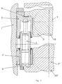
- Fig. 1
- einen Vertikalschnitt durch die Biege- und Ausbalanciervorrichtung
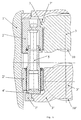
- Fig. 2
- einen Querschnitt gemäß der Linie B-B in
Figur 1 - Fig. 3
- einen Vertikalschnitt ähnlich
Figur 1 in einer abgewandelte Ausführung - Fig. 4
- eine weitere Ausbildung
- Im Fenster des Walzenständers 1 sind die Arbeitswalzeneinbaustücke 3 und 3' für die obere und untere Arbeitswalze 10 bzw. 10' angedeutet.
Der erfindungsgemäß geteilte Führungsblock ist am Fenster befestigt, wobei der obere Führungsblock 2 beweglich und der untere Führungsblock 2' ebenfalls beweglich oder ortsfest angeordnet sein kann.
Die Arbeitswalzeneinbaustücke 3 und 3' sind durch die Verschiebevorrichtung 6 und 6' in Achsrichtung der Arbeitswalzen verschiebbar.
Vertikal erfolgt die Positionsveränderung durch den Biege- und Balancierzylinder 5. - Dieser steht über Druckdeckel 4 bzw. 4' mit den Arbeitswalzeneinbaustücken - oder besser gesagt, mit den Ohren dieser - in Eingriff, wobei es für die Erfindung auch wesentlich ist, dass durch nur einen Biege- und Balancierzylinder 5 die Verbindung zu dem oberen Arbeitswalzeneinbaustück 3 und dem unteren Arbeitswalzeneinbaustück 3' gleichzeitig hergestellt wird.
- Bei der Ausführung nach
Figur 3 ist - in Abwandlung von der Ausführung nachFigur 1 - lediglich die Kolbenanordnung getauscht. - Eine negative oder positive Anstellung der Arbeitswalzeneinbaustücke wird mit der Ausführung erreicht, die in der
Figur 4 dargestellt ist. - Hierbei umklammert der Führungsblock 2 den Ansatz des Arbeitswalzeneinbaustücks 3 oder Druckdeckelerweiterungen 7 umklammern die Ohren der Arbeitswalzeneinbaustücke 3 bzw. 3', so dass die Bewegung des Biege- und Balancierzylinders in beiden Richtungen direkt übertragbar ist.
Claims (4)
- Biege- und Ausbalanciervorrichtung für axial verschiebbare Arbeitswalzen (10,10') eines Walzgerüstes, insbesondere eines Quartowalzgerüstes,
wobei beidseitig im Fenster jedes Walzenständers (1) Führungsblöcke (2) im Höhenbereich der Arbeitswalzeneinbaustücke (3,3') vorgesehen sind und die Kraft von Biege- und Balancierzylindern (5) auf die in Achsrichtung und vertikal verschiebbar geführten Arbeitswalzeneinbaustücke übertragbar ist,
dadurch gekennzeichnet,- dass die Führungsblöcke jeweils in einen oberen und einen unteren Führungsblock (2,2') unterteilt sind,- dass die oberen Führungsblöcke (2) im Fenster des Walzenständers (1) vertikal verschiebbar gelagert sind,- dass die unteren Führungsblöcke (2') im Fenster des Walzenständers (1) ortsfest oder ebenfalls vertikal verschiebbar gelagert sind und- dass in jedem der zusammengehörenden oberen und unteren Führungsblöcke (2,2') ein von diesen geführter Biege- und Balancierzylinder (5) angeordnet ist, der mit dem oberen und dem unteren Arbeitswalzeneinbaustück (3,3') in Eingriff steht. - Biege- und Ausbalanciervorrichtung nach Anspruch 1,
dadurch gekennzeichnet,
dass an dem oberen und dem unteren Führungsblock Verschiebevorrichtungen (6) für die Axialverschiebung der Arbeitswalzeneinbaustücke (3,3') einschließlich der Arbeitswalzenverriegelung (9) angeordnet sind. - Biege- und Ausbalanciervorrichtung nach einem der vorstehenden Ansprüche,
dadurch gekennzeichnet,
dass die Kraftübertragung von den Biege- und Balancierzylindern (5) auf die Arbeitswalzeneinbaustücke über an diesen anliegende Druckdeckel (4,4', 7) bzw. über die Führungsblöcke erfolgt. - Biege- und Ausbalanciervorrichtung nach Anspruch 3,
dadurch gekennzeichnet,
dass die Druckdeckel (4, 4') bzw. die Druckdeckelerweiterungen (7) Ohren der Arbeitswalzeneinbaustücke formschlüssig umklammern oder die Führungsblöcke (2, 2') Ansätze der Arbeitswalzeneinbaustücke (3, 3') umklammern.
Applications Claiming Priority (3)
| Application Number | Priority Date | Filing Date | Title |
|---|---|---|---|
| DE102009005964 | 2009-01-23 | ||
| DE102009058876A DE102009058876A1 (de) | 2009-01-23 | 2009-12-18 | Biege- und Ausbalanciervorrichtung für axial verschiebbare Arbeitswalzen eines Walzgerüstes |
| PCT/EP2010/000384 WO2010084011A1 (de) | 2009-01-23 | 2010-01-22 | Biege- und ausbalanciervorrichtung für axial verschiebbare arbeitswalzen eines walzgerüstes |
Publications (3)
| Publication Number | Publication Date |
|---|---|
| EP2389258A1 EP2389258A1 (de) | 2011-11-30 |
| EP2389258B1 true EP2389258B1 (de) | 2013-12-25 |
| EP2389258B2 EP2389258B2 (de) | 2017-09-27 |
Family
ID=42282777
Family Applications (1)
| Application Number | Title | Priority Date | Filing Date |
|---|---|---|---|
| EP10701472.2A Active EP2389258B2 (de) | 2009-01-23 | 2010-01-22 | Biege- und ausbalanciervorrichtung für axial verschiebbare arbeitswalzen eines walzgerüstes |
Country Status (12)
| Country | Link |
|---|---|
| US (1) | US9802231B2 (de) |
| EP (1) | EP2389258B2 (de) |
| JP (1) | JP5792068B2 (de) |
| KR (1) | KR101299940B1 (de) |
| CN (1) | CN102292171B (de) |
| BR (1) | BRPI1006952A2 (de) |
| DE (1) | DE102009058876A1 (de) |
| RU (1) | RU2478450C1 (de) |
| TW (1) | TWI451917B (de) |
| UA (1) | UA99880C2 (de) |
| WO (1) | WO2010084011A1 (de) |
| ZA (1) | ZA201102659B (de) |
Families Citing this family (5)
| Publication number | Priority date | Publication date | Assignee | Title |
|---|---|---|---|---|
| DE102017220560A1 (de) | 2017-05-03 | 2018-11-08 | Sms Group Gmbh | Walzgerüst zum Walzen eines metallischen Guts |
| IT201900000713A1 (it) * | 2019-01-17 | 2020-07-17 | Danieli Off Mecc | Sistema di bending e shifting per gabbie di laminazione |
| CN113102514A (zh) * | 2021-04-06 | 2021-07-13 | 广西钢铁集团有限公司 | 轧机传动轴托架的平衡装置 |
| CN113290097A (zh) * | 2021-06-30 | 2021-08-24 | 无锡周达冶金机械有限公司 | 一种s型插入件制造用轧机 |
| EP4190725A1 (de) | 2021-12-02 | 2023-06-07 | Primetals Technologies Austria GmbH | Transportvorrichtung und verfahren zum transportieren von metallbandbunden |
Family Cites Families (23)
| Publication number | Priority date | Publication date | Assignee | Title |
|---|---|---|---|---|
| EP0059417B1 (de) * | 1981-02-28 | 1985-01-02 | Sms Schloemann-Siemag Aktiengesellschaft | Walzgerüst |
| JPS59153505A (ja) * | 1983-02-22 | 1984-09-01 | Ishikawajima Harima Heavy Ind Co Ltd | 圧延機 |
| JPS6068103A (ja) * | 1983-09-22 | 1985-04-18 | Ishikawajima Harima Heavy Ind Co Ltd | 圧延機 |
| JPS617007A (ja) * | 1984-06-20 | 1986-01-13 | Ishikawajima Harima Heavy Ind Co Ltd | 圧延機 |
| DE3627692A1 (de) † | 1986-08-14 | 1988-02-25 | Schloemann Siemag Ag | Biege- und ausbalanciervorrichtung fuer axial verschiebbare arbeitswalzen eines quartowalzgeruestes |
| DE3627690A1 (de) | 1986-08-14 | 1988-02-25 | Schloemann Siemag Ag | Biege- und ausbalanciervorrichtung fuer axial verschiebbare arbeitswalzen eines quartowalzgeruestes |
| DE3638330A1 (de) * | 1986-11-10 | 1988-05-19 | Schloemann Siemag Ag | Walzgeruest mit einer vorrichtung zum axialen verschieben von anstellbaren walzen |
| FR2611541B1 (fr) * | 1987-02-27 | 1994-04-29 | Clecim Sa | Dispositif de reglage du profil et de repartition d'usure de cylindres dans un laminoir a cylindres deplacables axialement |
| DE3815454A1 (de) * | 1988-05-06 | 1989-11-16 | Schloemann Siemag Ag | Biege- und ausbalanciervorrichtung fuer axial verschiebbare walzen eines walzgeruestes |
| DE3843387A1 (de) * | 1988-12-23 | 1990-07-05 | Schloemann Siemag Ag | Vorrichtung zum walzenwechsel insbesondere der horizontal verschieblichen arbeitswalzen in einem walzgeruest |
| DE4034436A1 (de) * | 1990-10-29 | 1992-04-30 | Schloemann Siemag Ag | Walzgeruest mit anordnung zur distanzierten abstuetzung der oberen arbeitswalze |
| JP3258602B2 (ja) | 1997-07-18 | 2002-02-18 | 三光純薬株式会社 | 反応管攪拌装置 |
| DE19807785C1 (de) * | 1998-02-18 | 1999-03-04 | Mannesmann Ag | Biegevorrichtung für Vier- oder Mehrwalzengerüste |
| AT407124B (de) | 1998-10-19 | 2000-12-27 | Voest Alpine Ind Anlagen | Biegevorrichtung für zwei arbeitswalzen eines walzgerüstes |
| DE19922373A1 (de) * | 1999-05-14 | 2000-11-16 | Sms Demag Ag | Biegevorrichtung für die Arbeitswalzen eines Warmwalzgerüstes |
| TW501954B (en) | 2000-06-30 | 2002-09-11 | Sms Demag Ag | Roll stand, especially a duo or quarto roll stand, comprising bending and balancing devices for axially displaceable rollers |
| ITMI20011860A1 (it) * | 2001-09-04 | 2003-03-04 | Danieli Off Mecc | Gabbia di laminazione universale con controllo di luce dei cilindri |
| DE10312122B3 (de) * | 2003-03-13 | 2004-08-12 | Sms Demag Ag | Walzgerüst und Verfahren zur Einstellung des Walzgerüstes |
| DE10334682A1 (de) † | 2003-07-30 | 2005-02-17 | Sms Demag Ag | Walzvorrichtung |
| EP1772203A1 (de) * | 2005-10-10 | 2007-04-11 | VAI Industries (UK) Limited | Walzenbiegevorrichtung |
| AT504208B1 (de) * | 2006-04-21 | 2008-04-15 | Siemens Vai Metals Tech Gmbh | Biegevorrichtung für zwei arbeitswalzen eines walzgerüstes |
| DE102006032813A1 (de) * | 2006-07-14 | 2008-01-24 | Sms Demag Ag | Vorrichtung zur Drehverriegelung der Stützwalzenbalancierung von Walzgerüsten |
| DE102008035702A1 (de) * | 2008-07-30 | 2010-02-04 | Sms Siemag Aktiengesellschaft | Walzvorrichtung |
-
2009
- 2009-12-18 DE DE102009058876A patent/DE102009058876A1/de not_active Withdrawn
-
2010
- 2010-01-22 CN CN201080005558.9A patent/CN102292171B/zh active Active
- 2010-01-22 BR BRPI1006952A patent/BRPI1006952A2/pt not_active Application Discontinuation
- 2010-01-22 KR KR1020117009334A patent/KR101299940B1/ko not_active Expired - Fee Related
- 2010-01-22 JP JP2011536906A patent/JP5792068B2/ja active Active
- 2010-01-22 TW TW099101879A patent/TWI451917B/zh not_active IP Right Cessation
- 2010-01-22 EP EP10701472.2A patent/EP2389258B2/de active Active
- 2010-01-22 WO PCT/EP2010/000384 patent/WO2010084011A1/de not_active Ceased
- 2010-01-22 US US13/146,072 patent/US9802231B2/en not_active Expired - Fee Related
- 2010-01-22 UA UAA201110282A patent/UA99880C2/ru unknown
- 2010-01-22 RU RU2011135059/02A patent/RU2478450C1/ru active
-
2011
- 2011-04-11 ZA ZA2011/02659A patent/ZA201102659B/en unknown
Also Published As
| Publication number | Publication date |
|---|---|
| DE102009058876A1 (de) | 2010-07-29 |
| BRPI1006952A2 (pt) | 2016-04-12 |
| US20110283763A1 (en) | 2011-11-24 |
| CN102292171A (zh) | 2011-12-21 |
| ZA201102659B (en) | 2012-01-25 |
| KR20110059897A (ko) | 2011-06-07 |
| US9802231B2 (en) | 2017-10-31 |
| RU2478450C1 (ru) | 2013-04-10 |
| JP2012509768A (ja) | 2012-04-26 |
| EP2389258B2 (de) | 2017-09-27 |
| KR101299940B1 (ko) | 2013-08-26 |
| TWI451917B (zh) | 2014-09-11 |
| RU2011135059A (ru) | 2013-02-27 |
| EP2389258A1 (de) | 2011-11-30 |
| UA99880C2 (ru) | 2012-10-10 |
| CN102292171B (zh) | 2015-09-09 |
| JP5792068B2 (ja) | 2015-10-07 |
| TW201031474A (en) | 2010-09-01 |
| WO2010084011A1 (de) | 2010-07-29 |
Similar Documents
| Publication | Publication Date | Title |
|---|---|---|
| EP2389258B2 (de) | Biege- und ausbalanciervorrichtung für axial verschiebbare arbeitswalzen eines walzgerüstes | |
| EP1318879B1 (de) | Kombinierter antrieb für ein vierwalzen- bzw. sechswalzengerüst sowie betriebsverfahren hierfür | |
| EP0059417A1 (de) | Walzgerüst | |
| EP1181114B1 (de) | Biegevorrichtung für die arbeitswalzen eines warmwalzgerüstes | |
| DE19807785C1 (de) | Biegevorrichtung für Vier- oder Mehrwalzengerüste | |
| EP2509723B1 (de) | Walzgerüst zur herstellung von walzband | |
| EP1074315B1 (de) | Mehrwalzengerüst | |
| DE3504269A1 (de) | Druckmittelzylinder | |
| EP1687104B1 (de) | Anstellzylinder in walzgerüsten, unter anderem in vertikal-stauchgerüsten | |
| EP3328565B1 (de) | Walzenschliff zur gezielten vermeidung von viertelwellen | |
| EP0665067A1 (de) | Vielwalzengerüst in Ständerbauweise vorzugsweise mit direkter hydraulischer Anstellung | |
| EP0256408A2 (de) | Biege- und Ausbalanciervorrichtung für axial verschiebbare Arbeitswalzen eines Quartowalzgerüstes | |
| DE3104263A1 (de) | "hebelwerkzeug mit progressiver uebersetzung" | |
| DE69609565T2 (de) | Walzblock zum Krümmen und Ausbalancieren für Quartowalzgerüst zum Walzen von Band oder Blech | |
| EP0256410A2 (de) | Biege- und Ausbalanciervorrichtung für axial verschiebbare Arbeitswalzen eines Quartowalzgerüstes | |
| AT16770U1 (de) | Elastischer Übergang für Gleitstückadapter | |
| EP2310150A2 (de) | Walzenanordnung | |
| EP0019239B1 (de) | Verfahren und Vorrichtung zum Betrieb eines Bandwalzwerkes | |
| DE10027865C1 (de) | Vielwalzen-Walzwerk für Bandmaterial | |
| EP1500442B1 (de) | Biegevorrichtung für die Walzen eines Mehrwalzengerüstes | |
| EP3618979A1 (de) | Walzgerüst zum walzen eines metallischen guts | |
| DE102021208149A1 (de) | Verfahren und Anlage zum Warmwalzen von metallenem Walzgut | |
| DE102019200005A1 (de) | Walzvorrichtung | |
| WO2012049183A1 (de) | Walzgerüst | |
| DE20311456U1 (de) | Biegevorrichtung für die Walzen eines Mehrwalzengerüstes |
Legal Events
| Date | Code | Title | Description |
|---|---|---|---|
| PUAI | Public reference made under article 153(3) epc to a published international application that has entered the european phase |
Free format text: ORIGINAL CODE: 0009012 |
|
| 17P | Request for examination filed |
Effective date: 20110823 |
|
| AK | Designated contracting states |
Kind code of ref document: A1 Designated state(s): AT BE BG CH CY CZ DE DK EE ES FI FR GB GR HR HU IE IS IT LI LT LU LV MC MK MT NL NO PL PT RO SE SI SK SM TR |
|
| DAX | Request for extension of the european patent (deleted) | ||
| GRAP | Despatch of communication of intention to grant a patent |
Free format text: ORIGINAL CODE: EPIDOSNIGR1 |
|
| INTG | Intention to grant announced |
Effective date: 20130724 |
|
| GRAS | Grant fee paid |
Free format text: ORIGINAL CODE: EPIDOSNIGR3 |
|
| GRAA | (expected) grant |
Free format text: ORIGINAL CODE: 0009210 |
|
| AK | Designated contracting states |
Kind code of ref document: B1 Designated state(s): AT BE BG CH CY CZ DE DK EE ES FI FR GB GR HR HU IE IS IT LI LT LU LV MC MK MT NL NO PL PT RO SE SI SK SM TR |
|
| REG | Reference to a national code |
Ref country code: GB Ref legal event code: FG4D Free format text: NOT ENGLISH |
|
| REG | Reference to a national code |
Ref country code: CH Ref legal event code: EP |
|
| REG | Reference to a national code |
Ref country code: AT Ref legal event code: REF Ref document number: 646306 Country of ref document: AT Kind code of ref document: T Effective date: 20140115 |
|
| REG | Reference to a national code |
Ref country code: IE Ref legal event code: FG4D Free format text: LANGUAGE OF EP DOCUMENT: GERMAN |
|
| REG | Reference to a national code |
Ref country code: DE Ref legal event code: R096 Ref document number: 502010005755 Country of ref document: DE Effective date: 20140213 |
|
| PG25 | Lapsed in a contracting state [announced via postgrant information from national office to epo] |
Ref country code: SE Free format text: LAPSE BECAUSE OF FAILURE TO SUBMIT A TRANSLATION OF THE DESCRIPTION OR TO PAY THE FEE WITHIN THE PRESCRIBED TIME-LIMIT Effective date: 20131225 Ref country code: NO Free format text: LAPSE BECAUSE OF FAILURE TO SUBMIT A TRANSLATION OF THE DESCRIPTION OR TO PAY THE FEE WITHIN THE PRESCRIBED TIME-LIMIT Effective date: 20140325 Ref country code: HR Free format text: LAPSE BECAUSE OF FAILURE TO SUBMIT A TRANSLATION OF THE DESCRIPTION OR TO PAY THE FEE WITHIN THE PRESCRIBED TIME-LIMIT Effective date: 20131225 Ref country code: FI Free format text: LAPSE BECAUSE OF FAILURE TO SUBMIT A TRANSLATION OF THE DESCRIPTION OR TO PAY THE FEE WITHIN THE PRESCRIBED TIME-LIMIT Effective date: 20131225 Ref country code: LT Free format text: LAPSE BECAUSE OF FAILURE TO SUBMIT A TRANSLATION OF THE DESCRIPTION OR TO PAY THE FEE WITHIN THE PRESCRIBED TIME-LIMIT Effective date: 20131225 |
|
| REG | Reference to a national code |
Ref country code: NL Ref legal event code: VDEP Effective date: 20131225 |
|
| REG | Reference to a national code |
Ref country code: LT Ref legal event code: MG4D |
|
| PG25 | Lapsed in a contracting state [announced via postgrant information from national office to epo] |
Ref country code: LV Free format text: LAPSE BECAUSE OF FAILURE TO SUBMIT A TRANSLATION OF THE DESCRIPTION OR TO PAY THE FEE WITHIN THE PRESCRIBED TIME-LIMIT Effective date: 20131225 |
|
| BERE | Be: lapsed |
Owner name: SMS SIEMAG AG Effective date: 20140131 |
|
| PG25 | Lapsed in a contracting state [announced via postgrant information from national office to epo] |
Ref country code: IS Free format text: LAPSE BECAUSE OF FAILURE TO SUBMIT A TRANSLATION OF THE DESCRIPTION OR TO PAY THE FEE WITHIN THE PRESCRIBED TIME-LIMIT Effective date: 20140425 Ref country code: EE Free format text: LAPSE BECAUSE OF FAILURE TO SUBMIT A TRANSLATION OF THE DESCRIPTION OR TO PAY THE FEE WITHIN THE PRESCRIBED TIME-LIMIT Effective date: 20131225 |
|
| PG25 | Lapsed in a contracting state [announced via postgrant information from national office to epo] |
Ref country code: SK Free format text: LAPSE BECAUSE OF FAILURE TO SUBMIT A TRANSLATION OF THE DESCRIPTION OR TO PAY THE FEE WITHIN THE PRESCRIBED TIME-LIMIT Effective date: 20131225 Ref country code: CY Free format text: LAPSE BECAUSE OF FAILURE TO SUBMIT A TRANSLATION OF THE DESCRIPTION OR TO PAY THE FEE WITHIN THE PRESCRIBED TIME-LIMIT Effective date: 20131225 Ref country code: CZ Free format text: LAPSE BECAUSE OF FAILURE TO SUBMIT A TRANSLATION OF THE DESCRIPTION OR TO PAY THE FEE WITHIN THE PRESCRIBED TIME-LIMIT Effective date: 20131225 Ref country code: PT Free format text: LAPSE BECAUSE OF FAILURE TO SUBMIT A TRANSLATION OF THE DESCRIPTION OR TO PAY THE FEE WITHIN THE PRESCRIBED TIME-LIMIT Effective date: 20140428 Ref country code: LU Free format text: LAPSE BECAUSE OF FAILURE TO SUBMIT A TRANSLATION OF THE DESCRIPTION OR TO PAY THE FEE WITHIN THE PRESCRIBED TIME-LIMIT Effective date: 20140122 Ref country code: ES Free format text: LAPSE BECAUSE OF FAILURE TO SUBMIT A TRANSLATION OF THE DESCRIPTION OR TO PAY THE FEE WITHIN THE PRESCRIBED TIME-LIMIT Effective date: 20131225 Ref country code: NL Free format text: LAPSE BECAUSE OF FAILURE TO SUBMIT A TRANSLATION OF THE DESCRIPTION OR TO PAY THE FEE WITHIN THE PRESCRIBED TIME-LIMIT Effective date: 20131225 Ref country code: RO Free format text: LAPSE BECAUSE OF FAILURE TO SUBMIT A TRANSLATION OF THE DESCRIPTION OR TO PAY THE FEE WITHIN THE PRESCRIBED TIME-LIMIT Effective date: 20131225 |
|
| REG | Reference to a national code |
Ref country code: CH Ref legal event code: PL |
|
| REG | Reference to a national code |
Ref country code: DE Ref legal event code: R026 Ref document number: 502010005755 Country of ref document: DE |
|
| PLBI | Opposition filed |
Free format text: ORIGINAL CODE: 0009260 |
|
| PG25 | Lapsed in a contracting state [announced via postgrant information from national office to epo] |
Ref country code: MC Free format text: LAPSE BECAUSE OF FAILURE TO SUBMIT A TRANSLATION OF THE DESCRIPTION OR TO PAY THE FEE WITHIN THE PRESCRIBED TIME-LIMIT Effective date: 20131225 |
|
| 26 | Opposition filed |
Opponent name: SIEMENS VAI METALS TECHNOLOGIES GMBH Effective date: 20140912 |
|
| PLAX | Notice of opposition and request to file observation + time limit sent |
Free format text: ORIGINAL CODE: EPIDOSNOBS2 |
|
| PG25 | Lapsed in a contracting state [announced via postgrant information from national office to epo] |
Ref country code: CH Free format text: LAPSE BECAUSE OF NON-PAYMENT OF DUE FEES Effective date: 20140131 Ref country code: DK Free format text: LAPSE BECAUSE OF FAILURE TO SUBMIT A TRANSLATION OF THE DESCRIPTION OR TO PAY THE FEE WITHIN THE PRESCRIBED TIME-LIMIT Effective date: 20131225 Ref country code: LI Free format text: LAPSE BECAUSE OF NON-PAYMENT OF DUE FEES Effective date: 20140131 |
|
| REG | Reference to a national code |
Ref country code: FR Ref legal event code: ST Effective date: 20140930 |
|
| REG | Reference to a national code |
Ref country code: IE Ref legal event code: MM4A |
|
| REG | Reference to a national code |
Ref country code: DE Ref legal event code: R026 Ref document number: 502010005755 Country of ref document: DE Effective date: 20140912 |
|
| PG25 | Lapsed in a contracting state [announced via postgrant information from national office to epo] |
Ref country code: FR Free format text: LAPSE BECAUSE OF NON-PAYMENT OF DUE FEES Effective date: 20140225 Ref country code: PL Free format text: LAPSE BECAUSE OF FAILURE TO SUBMIT A TRANSLATION OF THE DESCRIPTION OR TO PAY THE FEE WITHIN THE PRESCRIBED TIME-LIMIT Effective date: 20131225 |
|
| PG25 | Lapsed in a contracting state [announced via postgrant information from national office to epo] |
Ref country code: BE Free format text: LAPSE BECAUSE OF NON-PAYMENT OF DUE FEES Effective date: 20140131 Ref country code: IE Free format text: LAPSE BECAUSE OF NON-PAYMENT OF DUE FEES Effective date: 20140122 |
|
| PLAF | Information modified related to communication of a notice of opposition and request to file observations + time limit |
Free format text: ORIGINAL CODE: EPIDOSCOBS2 |
|
| PLAF | Information modified related to communication of a notice of opposition and request to file observations + time limit |
Free format text: ORIGINAL CODE: EPIDOSCOBS2 |
|
| PG25 | Lapsed in a contracting state [announced via postgrant information from national office to epo] |
Ref country code: SI Free format text: LAPSE BECAUSE OF FAILURE TO SUBMIT A TRANSLATION OF THE DESCRIPTION OR TO PAY THE FEE WITHIN THE PRESCRIBED TIME-LIMIT Effective date: 20131225 |
|
| PLBB | Reply of patent proprietor to notice(s) of opposition received |
Free format text: ORIGINAL CODE: EPIDOSNOBS3 |
|
| RAP2 | Party data changed (patent owner data changed or rights of a patent transferred) |
Owner name: SMS GROUP GMBH |
|
| REG | Reference to a national code |
Ref country code: DE Ref legal event code: R082 Ref document number: 502010005755 Country of ref document: DE Representative=s name: HEMMERICH & KOLLEGEN, DE Ref country code: DE Ref legal event code: R081 Ref document number: 502010005755 Country of ref document: DE Owner name: SMS GROUP GMBH, DE Free format text: FORMER OWNER: SMS SIEMAG AG, 40237 DUESSELDORF, DE |
|
| PG25 | Lapsed in a contracting state [announced via postgrant information from national office to epo] |
Ref country code: MT Free format text: LAPSE BECAUSE OF FAILURE TO SUBMIT A TRANSLATION OF THE DESCRIPTION OR TO PAY THE FEE WITHIN THE PRESCRIBED TIME-LIMIT Effective date: 20131225 |
|
| PG25 | Lapsed in a contracting state [announced via postgrant information from national office to epo] |
Ref country code: SM Free format text: LAPSE BECAUSE OF FAILURE TO SUBMIT A TRANSLATION OF THE DESCRIPTION OR TO PAY THE FEE WITHIN THE PRESCRIBED TIME-LIMIT Effective date: 20131225 |
|
| PG25 | Lapsed in a contracting state [announced via postgrant information from national office to epo] |
Ref country code: GR Free format text: LAPSE BECAUSE OF FAILURE TO SUBMIT A TRANSLATION OF THE DESCRIPTION OR TO PAY THE FEE WITHIN THE PRESCRIBED TIME-LIMIT Effective date: 20140326 Ref country code: BG Free format text: LAPSE BECAUSE OF FAILURE TO SUBMIT A TRANSLATION OF THE DESCRIPTION OR TO PAY THE FEE WITHIN THE PRESCRIBED TIME-LIMIT Effective date: 20131225 |
|
| PG25 | Lapsed in a contracting state [announced via postgrant information from national office to epo] |
Ref country code: HU Free format text: LAPSE BECAUSE OF FAILURE TO SUBMIT A TRANSLATION OF THE DESCRIPTION OR TO PAY THE FEE WITHIN THE PRESCRIBED TIME-LIMIT; INVALID AB INITIO Effective date: 20100122 |
|
| PLAB | Opposition data, opponent's data or that of the opponent's representative modified |
Free format text: ORIGINAL CODE: 0009299OPPO |
|
| R26 | Opposition filed (corrected) |
Opponent name: PRIMETALS TECHNOLOGIES AUSTRIA GMBH Effective date: 20140912 |
|
| PGFP | Annual fee paid to national office [announced via postgrant information from national office to epo] |
Ref country code: TR Payment date: 20170112 Year of fee payment: 8 |
|
| PUAH | Patent maintained in amended form |
Free format text: ORIGINAL CODE: 0009272 |
|
| STAA | Information on the status of an ep patent application or granted ep patent |
Free format text: STATUS: PATENT MAINTAINED AS AMENDED |
|
| 27A | Patent maintained in amended form |
Effective date: 20170927 |
|
| AK | Designated contracting states |
Kind code of ref document: B2 Designated state(s): AT BE BG CH CY CZ DE DK EE ES FI FR GB GR HR HU IE IS IT LI LT LU LV MC MK MT NL NO PL PT RO SE SI SK SM TR |
|
| REG | Reference to a national code |
Ref country code: DE Ref legal event code: R102 Ref document number: 502010005755 Country of ref document: DE |
|
| PG25 | Lapsed in a contracting state [announced via postgrant information from national office to epo] |
Ref country code: MK Free format text: LAPSE BECAUSE OF FAILURE TO SUBMIT A TRANSLATION OF THE DESCRIPTION OR TO PAY THE FEE WITHIN THE PRESCRIBED TIME-LIMIT Effective date: 20131225 |
|
| PG25 | Lapsed in a contracting state [announced via postgrant information from national office to epo] |
Ref country code: TR Free format text: LAPSE BECAUSE OF NON-PAYMENT OF DUE FEES Effective date: 20180122 |
|
| P01 | Opt-out of the competence of the unified patent court (upc) registered |
Effective date: 20230707 |
|
| PGFP | Annual fee paid to national office [announced via postgrant information from national office to epo] |
Ref country code: GB Payment date: 20240119 Year of fee payment: 15 |
|
| GBPC | Gb: european patent ceased through non-payment of renewal fee |
Effective date: 20250122 |
|
| PG25 | Lapsed in a contracting state [announced via postgrant information from national office to epo] |
Ref country code: GB Free format text: LAPSE BECAUSE OF NON-PAYMENT OF DUE FEES Effective date: 20250122 |
|
| PGFP | Annual fee paid to national office [announced via postgrant information from national office to epo] |
Ref country code: DE Payment date: 20260121 Year of fee payment: 17 |
|
| PGFP | Annual fee paid to national office [announced via postgrant information from national office to epo] |
Ref country code: AT Payment date: 20260122 Year of fee payment: 17 |
|
| PGFP | Annual fee paid to national office [announced via postgrant information from national office to epo] |
Ref country code: IT Payment date: 20260126 Year of fee payment: 17 |