EP2374957B1 - Process for manufacturing an insulating composite building block and block produced by this process - Google Patents
Process for manufacturing an insulating composite building block and block produced by this process Download PDFInfo
- Publication number
- EP2374957B1 EP2374957B1 EP11305399.5A EP11305399A EP2374957B1 EP 2374957 B1 EP2374957 B1 EP 2374957B1 EP 11305399 A EP11305399 A EP 11305399A EP 2374957 B1 EP2374957 B1 EP 2374957B1
- Authority
- EP
- European Patent Office
- Prior art keywords
- block
- building block
- cutout
- load
- lateral
- Prior art date
- Legal status (The legal status is an assumption and is not a legal conclusion. Google has not performed a legal analysis and makes no representation as to the accuracy of the status listed.)
- Revoked
Links
- 239000002131 composite material Substances 0.000 title claims description 39
- 238000000034 method Methods 0.000 title claims description 18
- 238000004519 manufacturing process Methods 0.000 title claims description 16
- 239000011810 insulating material Substances 0.000 claims description 25
- 239000000463 material Substances 0.000 claims description 19
- 230000015572 biosynthetic process Effects 0.000 claims description 12
- 230000000295 complement effect Effects 0.000 claims description 12
- 238000005755 formation reaction Methods 0.000 claims description 12
- 239000000470 constituent Substances 0.000 claims description 8
- 238000000465 moulding Methods 0.000 claims description 8
- 239000007787 solid Substances 0.000 claims description 8
- 239000011230 binding agent Substances 0.000 claims description 7
- 239000004568 cement Substances 0.000 claims description 3
- 238000005187 foaming Methods 0.000 claims description 2
- 238000003754 machining Methods 0.000 claims description 2
- 239000000203 mixture Substances 0.000 claims description 2
- 230000008878 coupling Effects 0.000 claims 5
- 238000010168 coupling process Methods 0.000 claims 5
- 238000005859 coupling reaction Methods 0.000 claims 5
- 238000004026 adhesive bonding Methods 0.000 claims 1
- 230000001413 cellular effect Effects 0.000 claims 1
- 238000009432 framing Methods 0.000 claims 1
- 239000012876 carrier material Substances 0.000 description 17
- 238000010276 construction Methods 0.000 description 17
- 239000004567 concrete Substances 0.000 description 8
- 238000009413 insulation Methods 0.000 description 4
- 238000004873 anchoring Methods 0.000 description 3
- 230000000903 blocking effect Effects 0.000 description 3
- 239000004794 expanded polystyrene Substances 0.000 description 2
- 238000000926 separation method Methods 0.000 description 2
- 238000005266 casting Methods 0.000 description 1
- 230000006835 compression Effects 0.000 description 1
- 238000007906 compression Methods 0.000 description 1
- 230000009193 crawling Effects 0.000 description 1
- 230000007547 defect Effects 0.000 description 1
- 239000012467 final product Substances 0.000 description 1
- 239000012530 fluid Substances 0.000 description 1
- 239000003292 glue Substances 0.000 description 1
- 238000002347 injection Methods 0.000 description 1
- 239000007924 injection Substances 0.000 description 1
- 238000003780 insertion Methods 0.000 description 1
- 230000037431 insertion Effects 0.000 description 1
- 238000005304 joining Methods 0.000 description 1
- 238000012986 modification Methods 0.000 description 1
- 230000004048 modification Effects 0.000 description 1
- 230000002093 peripheral effect Effects 0.000 description 1
- 239000000047 product Substances 0.000 description 1
- 238000011084 recovery Methods 0.000 description 1
- 238000004513 sizing Methods 0.000 description 1
- 238000007711 solidification Methods 0.000 description 1
- 230000008023 solidification Effects 0.000 description 1
- 239000000243 solution Substances 0.000 description 1
- 238000006467 substitution reaction Methods 0.000 description 1
Images


Classifications
-
- E—FIXED CONSTRUCTIONS
- E04—BUILDING
- E04C—STRUCTURAL ELEMENTS; BUILDING MATERIALS
- E04C1/00—Building elements of block or other shape for the construction of parts of buildings
- E04C1/40—Building elements of block or other shape for the construction of parts of buildings built-up from parts of different materials, e.g. composed of layers of different materials or stones with filling material or with insulating inserts
- E04C1/41—Building elements of block or other shape for the construction of parts of buildings built-up from parts of different materials, e.g. composed of layers of different materials or stones with filling material or with insulating inserts composed of insulating material and load-bearing concrete, stone or stone-like material
-
- E—FIXED CONSTRUCTIONS
- E04—BUILDING
- E04B—GENERAL BUILDING CONSTRUCTIONS; WALLS, e.g. PARTITIONS; ROOFS; FLOORS; CEILINGS; INSULATION OR OTHER PROTECTION OF BUILDINGS
- E04B2/00—Walls, e.g. partitions, for buildings; Wall construction with regard to insulation; Connections specially adapted to walls
- E04B2/02—Walls, e.g. partitions, for buildings; Wall construction with regard to insulation; Connections specially adapted to walls built-up from layers of building elements
- E04B2002/0202—Details of connections
- E04B2002/0204—Non-undercut connections, e.g. tongue and groove connections
- E04B2002/0208—Non-undercut connections, e.g. tongue and groove connections of trapezoidal shape
Landscapes
- Engineering & Computer Science (AREA)
- Architecture (AREA)
- Civil Engineering (AREA)
- Structural Engineering (AREA)
- Building Environments (AREA)
Description
La présente invention concerne le domaine des éléments de construction en forme de blocs, notamment de blocs à bancher du genre parpaing, et a pour objet un bloc de construction composite du type parpaing isolant.The present invention relates to the field of block-shaped building elements, including bancher blocks of the crawling type, and relates to a composite building block of the block-type insulation.
On sait que les parpaings classiques utilisés en construction pour la réalisation notamment de murs extérieurs présentent une forme globalement parallélépipédique et sont destinés à être empilés les uns sur les autres par rangs successifs.It is known that the conventional blocks used in construction for the realization in particular of external walls have a generally parallelepiped shape and are intended to be stacked on top of each other in successive rows.
Parmi ces parpaings réalisés entièrement en un matériau porteur, on connaît notamment ceux qui se présentent sous la forme d'un corps creux profilé de forme parallélépipédique, dont les parois latérales délimitent au moins deux alvéoles, ouvertes vers le dessus et vers le dessous de ce bloc.Among these blocks made entirely of a carrier material, are particularly known those which are in the form of a shaped hollow body of parallelepiped shape, whose side walls define at least two cells, open towards the top and towards the bottom of this block.
Après empilement, un matériau fluide intégrant un liant hydraulique, par exemple du type béton, est injecté dans les alignements d'alvéoles résultant des rangées superposées de blocs, afin de créer l'ossature du mur résultant après solidification.After stacking, a fluid material incorporating a hydraulic binder, for example of the concrete type, is injected into the cell alignments resulting from the superimposed rows of blocks, in order to create the framework of the resulting wall after solidification.
Il est également connu actuellement d'utiliser, pour une meilleure isolation phonique et thermique des murs, des parpaings isolants qui sont généralement constitués d'une structure consistant en un assemblage de deux éléments constitutifs, dont l'un, situé du côté interne de la construction, est un bloc en matériau porteur (béton, bois-ciment ou autre) et l'autre, situé du côté externe de la construction, est un élément isolant rigide, généralement en polystyrène expansé ou analogue.It is also currently known to use, for better acoustic and thermal insulation of walls, insulating blocks which are generally constituted by a structure consisting of an assembly of two constituent elements, one of which, located on the internal side of the construction, is a block of carrier material (concrete, wood-cement or other) and the other, located on the outer side of the construction, is a rigid insulating member, usually expanded polystyrene or the like.
Un tel bloc en béton constitutif d'un parpaing isolant comporte généralement un ou plusieurs sites d'assemblage avec un élément isolant qui consistent en une ou plusieurs parties mâles ou tenons, destinés à venir s'insérer étroitement dans une partie femelle complémentaire ou mortaise, pratiquée dans l'élément isolant correspondant, et dont la forme desdites parties mâle/femelle, par exemple en queue d'aronde, est déterminée de manière que leur liaison mécanique puisse s'opposer à leur séparation lorsqu'elle sont soumises à une force de traction extérieur.Such a concrete block constituting an insulating block generally comprises one or more assembly sites with an insulating element which consist of one or more male parts or tenons, intended to fit tightly in a complementary female part or mortise, formed in the corresponding insulating element, and the shape of said male / female parts, for example dovetail, is determined so that their mechanical connection can oppose their separation when subjected to a force of external traction.
En outre, une ou plusieurs alvéoles, formées par la réunion de la partie en béton avec l'élément isolant complémentaire correspondant, constituent, lors du montage des parpaings les uns sur les autres pour la construction d'un mur et comme indiqué ci-dessus pour les parpaings classiques, des compartiments verticaux dans ledit mur qui sont destinés à être remplis de béton, ceci de manière à auto-verrouiller lesdits parpaings les uns sur les autres et à réaliser une succession de poteaux en béton constituant, avec les chaînages horizontaux, l'ossature dudit mur.In addition, one or more cells, formed by joining the concrete part with the corresponding complementary insulating element, constitute, when assembling the blocks on top of each other for the construction of a wall and as indicated above for conventional blocks, vertical compartments in said wall which are intended to be filled with concrete, so as to auto locking said blocks on each other and to achieve a succession of concrete posts constituting, with the horizontal chaining, the frame of said wall.
Par les documents
Toutefois, ces réalisations de parpaings isolants connus nécessitent obligatoirement la mise au point de nouveaux moules pour la composante porteuse et le moulage délicat de sites d'accrochage de forme complexe. En outre, la résistance de l'assemblage entre les deux composantes est souvent limitée, ce qui peut résulter en un décrochement ou une séparation des deux composantes sous la pression du béton injecté dans les alvéoles, ou en la rupture de l'une des deux composantes.However, these achievements of known insulating blocks necessarily require the development of new molds for the carrier component and the delicate molding of complex shaped fastening sites. In addition, the resistance of the assembly between the two components is often limited, which can result in a recess or separation of the two components under the pressure of the concrete injected into the cells, or in the rupture of one of the two components. components.
Par ailleurs, on connaît par le document
Le but recherché dans ce document antérieur est de subdiviser le corps structurel du bloc de construction en des parties isolées thermiquement l'une de l'autre par un ou des inserts isolants.The object sought in this prior document is to subdivide the structural body of the building block into parts thermally insulated from one another by one or more insulating inserts.
A cet effet, les éléments isolants en forme de plaquettes sont arrangés pour être disposés entièrement à l'intérieur du bloc de construction, en tant qu'inserts, c'est-à-dire sans être en contact avec les faces extérieures de ces blocs de construction et a fortiori sans former un côté extérieur de ces blocs. En particulier, les faces intérieure et extérieure de ce bloc de construction sont toujours formées par le corps structurel.For this purpose, the insulating elements in the form of platelets are arranged to be arranged entirely inside the building block, as inserts, that is to say without being in contact with the outer faces of these blocks. of construction and a fortiori without forming an outer side of these blocks. In particular, the inner and outer faces of this building block are always formed by the structural body.
Enfin, le document
Les parois du bloc formant la partie structurelle présentent une constitution double et multialvéolaire autour d'alvéoles centrales et les rainures sont formées grâce à une pluralité de découpes en forme de fentes ménagées dans l'épaisseur de la peau extérieure de la paroi de la première partie structurelle.The walls of the block forming the structural part have a double and multi-cellular constitution around central cells and the grooves are formed by a plurality of slit-like cuts in the thickness of the outer skin of the wall of the first part. structural.
La constitution complexe de la partie structurelle (parois doubles et multialvéolaires) entraîne une fabrication relativement délicate et un surcoût important pour le bloc de construction.The complex constitution of the structural part (double and multi-cellular walls) leads to a relatively delicate fabrication and a significant additional cost for the building block.
De plus, l'accrochage périphérique de la partie isolante dans des rainures de faible taille et avec une reprise au niveau d'une peau externe uniquement de la paroi, ne permet pas d'aboutir à un assemblage résistant entre les deux composantes et limite de ce fait également l'épaisseur de la plaque isolante pouvant être solidarisée et les contraintes auxquelles cette dernière peut être soumise et pouvant être transmises à la partie structurelle.In addition, the peripheral attachment of the insulating part in small grooves and with a recovery at an outer skin only of the wall, does not lead to a resistant assembly between the two components and limit of this also the thickness of the insulating plate that can be secured and the stresses to which it can be subjected and can be transmitted to the structural part.
La présente invention a pour objet de pallier au moins certains des inconvénients précités des solutions existantes, tout en présentant préférentiellement des performances au moins équivalentes au niveau du produit final.The present invention aims to overcome at least some of the aforementioned drawbacks of existing solutions, while preferably having at least equivalent performance at the level of the final product.
A cet effet, elle a pour objet un procédé de fabrication d'un bloc de construction composite du type parpaing isolant, selon le préambule de la revendication 1 et présentant en combinaison les caractéristiques de la partie caractérisante de cette revendication.For this purpose, it relates to a method of manufacturing a composite building block of the block-insulating type, according to the preamble of
L'invention concerne également un bloc de construction du type mentionné dans le préambule de la revendication 10 et présentant en combinaison les caractéristiques de la partie caractérisante de cette revendication.The invention also relates to a building block of the type mentioned in the preamble of
L'invention sera mieux comprise grâce à la description ci-après, qui se rapporte à des modes de réalisation préférés, donnés à titre d'exemples non limitatifs, et expliqués avec référence aux dessins schématiques annexés, dans lesquels :
- la
figure 1 est une vue de dessus d'un bloc de construction composite selon un premier mode de réalisation de l'invention ; - la
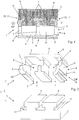
figure 2 est une vue éclatée en perspective du bloc de construction de lafigure 1 , séparé en ses deux composantes ; - la
figure 3 est une vue de dessus d'un bloc de construction composite selon un second mode de réalisation de l'invention ; - la
figure 4 est une vue en perspective d'un bloc de construction creux en un matériau porteur formant la première composante du bloc composite de lafigure 3 ; - la
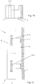
figure 5 est une vue en élévation latérale du bloc composite représentéfigure 3 ; - la
figure 6 est une vue de dessus d'une partie de mur réalisée par juxtaposition de deux blocs courants selon lafigure 1 et d'un bloc d'angle selon lafigure 3 ; - les
figures 7 à 9 sont des vues de dessus de trois variantes de réalisation du bloc composite représentéfigure 1 ; - la
figure 10 et une vue en élévation latérale d'un bloc de construction composite selon un troisième mode de réalisation de l'invention ; - la
figure 11 est une vue de dessus d'une partie de mur formée par deux blocs tels que représentés sur lafigure 10 disposés attenants côte à côte, et, - les
figures 12A à 12C sont des vues respectivement de dessus, en élévation frontale et en élévation latérale de la première composante porteuse faisant partie du bloc représentéfigure 10 .
- the
figure 1 is a top view of a composite building block according to a first embodiment of the invention; - the
figure 2 is an exploded perspective view of the building block of thefigure 1 separated into its two components; - the
figure 3 is a top view of a composite building block according to a second embodiment of the invention; - the
figure 4 is a perspective view of a hollow building block made of a carrier material forming the first component of the composite block of thefigure 3 ; - the
figure 5 is a side elevational view of the composite block shownfigure 3 ; - the
figure 6 is a top view of a wall portion made by juxtaposing two current blocks according to thefigure 1 and a corner block according to thefigure 3 ; - the
Figures 7 to 9 are top views of three alternative embodiments of the composite block shownfigure 1 ; - the
figure 10 and a side elevational view of a composite building block according to a third embodiment of the invention; - the
figure 11 is a top view of a wall portion formed by two blocks as shown in FIG.figure 10 arranged side by side, and, - the
Figures 12A to 12C are views respectively from above, in front elevation and in lateral elevation of the first carrier component forming part of the block shownfigure 10 .
L'invention concerne un procédé de fabrication d'un bloc 1 de construction composite du type parpaing isolant, comprenant une première composante ou partie constitutive 2 en un matériau porteur et une seconde composante ou partie constitutive 3 en un matériau isolant rigide, les deux composantes étant au moins partiellement imbriquées l'une dans l'autre et chaque composante formant une partie volumique propre du bloc 1 composite, ainsi qu'au moins une face extérieure de ce dernier.The invention relates to a method for manufacturing a
Ce procédé consiste à fournir,
d'une part, un bloc de construction creux 2 en un matériau porteur de forme générale parallélépipédique avec une face supérieure 4, une face inférieure 4' et des faces latérales 4", ledit bloc étant constitué par des portions de parois latérales 5 profilées délimitant ensemble au moins une alvéole 6 ouverte au niveau des faces supérieure et inférieure précitées et la ou les portions de paroi 5 d'au moins une face latérale 4", ou le cas échéant de deux faces latérales 4" mutuellement attenantes, étant pourvues d'au moins une découpe 7, 7' profilée s'étendant dans une direction DP perpendiculaire aux faces supérieure 4 et inférieure 4', le cas échéant sur la totalité de la hauteur de la ou d'au moins certaines desdites portions de paroi 5 concernées, et,
d'autre part, un bloc 3 de matériau isolant rigide conformé pour venir en application intime contre ou être positionné à distance de la ou des face(s) latérale(s) extérieure(s) 8 du bloc de construction creux 2 comportant la ou les découpes 7, 7' et présentant une ou des formations saillantes 9 destinées à venir s'ancrer, par coopération de formes complémentaires, dans l'alvéole ou les alvéoles 6, ce à travers une ou des ouverture(s) dans la ou les portion(s) de paroi(s) 5 correspondant à la ou aux découpes 7, 7',
et, ensuite, à assembler les deux composantes 2 et 3 précitées pour réaliser un bloc de construction composite 1, ce par un mouvement d'emboîtement mutuel dans une direction DP perpendiculaire aux faces supérieure 4 et inférieure 4' du bloc 2 de construction en matériau porteur formant la première composante.This method consists in providing,
on the one hand, a
on the other hand, a
and then, to assemble the two
Le bloc de construction composite 1 peut se présenter sous la forme d'un bloc « courant », comme représenté sur les
Grâce à l'ancrage direct du bloc de matériau isolant rigide 3 (par exemple en polystyrène expansé) dans l'alvéole ou les alvéoles 6 centrale(s) du bloc 2, destinée(s) à recevoir le liant formant l'ossature du mur, on peut s'affranchir de la réalisation de sites d'accrochage supplémentaires de forme complexe pour réaliser l'assemblage des deux blocs.Thanks to the direct anchoring of the block of rigid insulating material 3 (for example expanded polystyrene) in the cell or
De plus, l'assemblage en lui-même est facilité puisqu'il peut être réalisé par simple emboîtement avec une imbrication mutuelle importante des deux composantes, le cas échéant sans nécessiter aucun autre moyen de blocage ou de verrouillage (un point de colle ou une légère compression peut être envisagé(e)).In addition, the assembly itself is facilitated since it can be achieved by simple interlocking with a significant mutual interlocking of the two components, if necessary without requiring any other locking or locking means (a glue point or a slight compression may be considered).
Enfin, on aboutit à une grande cohésion structurelle du bloc composite 1 et à une résistance élevée de l'assemblage des deux composantes 2 et 3, du fait de l'importance des masses de matériaux différents mutuellement emboîtées, de l'importance des surfaces en contact au niveau des interfaces des deux composantes et de la taille importante de la ou des formations saillantes 9 s'étendant dans l'alvéole ou les alvéoles 6.Finally, it leads to a high structural cohesion of the
Enfin, le blocage définitif des deux composantes de chaque bloc composite entre elles s'effectue lors de l'injection du liant hydraulique dans les alignements d'alvéoles pour former l'ossature du mur et de ce fait les trois matériaux se retrouvent en contact direct et intime, sur des surfaces importantes et de manière mutuellement imbriquée, avec un autocalage final et un verrouillage automatique compensant les éventuels jeux ou défauts de dimensionnement des deux composantes du bloc composite au niveau de leurs parties mutuellement imbriquées.Finally, the final blocking of the two components of each composite block between them occurs during the injection of the hydraulic binder in the cell alignments to form the frame of the wall and thus the three materials are found in direct and intimate contact, on important surfaces and in a mutually overlapping manner, with a final self-leveling and an automatic locking compensating for possible games or sizing defects of the two components of the composite block at their mutually interleaved parts.
Cet ancrage au coeur du bloc 3 isolant dans le bloc creux porteur 2 permet audit bloc 3 de supporter des contraintes importantes, notamment dans les deux directions perpendiculaires à la face considérée.This anchoring at the heart of the
En particulier, le bloc 3 pourra présenter une épaisseur importante, permettant d'aboutir à un degré d'isolation thermique élevé même avec des blocs porteurs 2 à simple paroi (pleine), aisés à fabriquer, en lieu et place de blocs porteurs 2 à paroi double pour multialvéolaire.In particular, the
Préférentiellement, le bloc creux porteur 2 comporte au moins deux alvéoles 6 qui ne sont que partiellement remplies par les formations saillantes 9 et le bloc 3 isolant est plaqué contre la face extérieure dudit bloc 2.Preferably, the
Comme le montrent les
Selon un mode de réalisation préféré, le procédé selon l'invention peut consister à fabriquer préalablement un bloc de construction creux 2 en matériau porteur avec des portions de parois latérales 5 pleines, puis à ménager la ou les découpe(s) partielle(s) ou traversante(s) 7, 7' dans la ou les portion(s) de paroi(s) 5 concernée(s), ce par l'intermédiaire d'une opération consécutive d'usinage ou analogue.According to a preferred embodiment, the method according to the invention may consist of producing beforehand a
De manière pratique et selon une variante de mise en oeuvre particulièrement avantageuse, notamment du point de vue économique, il peut être prévu que le bloc de construction creux 2 initial, à portions de parois latérales 5 pleines ou entières, est obtenu par moulage, par exemple d'un mélange bois-ciment, dans un moule existant utilisé pour la réalisation de blocs de construction creux à alvéoles.In a practical way and according to a particularly advantageous variant of implementation, particularly from the economic point of view, it may be envisaged that the initial
Selon une autre variante de réalisation du procédé, il peut être prévu de fabriquer le bloc de construction creux 2 en matériau porteur, pourvu de sa ou de ses découpe(s) 7, 7', par moulage dans un moule existant, utilisé pour la réalisation de blocs de construction creux à portions de parois latérales 5 pleines ou entières, mais pourvue d'une ou de plusieurs formations internes supplémentaires, saillantes dans le volume interne du moule et de forme complémentaire à la ou aux découpe(s) 7, 7'.According to another alternative embodiment of the method, it may be provided to manufacture the
Les formations internes supplémentaires peuvent consister en des pièces rapportées positionnées dans le moule existant ou en des tiroirs modifiés ou additionnels faisant partie d'un moule à tiroirs existant.Additional internal formations may consist of inserts positioned in the existing mold or of modified or additional drawers forming part of an existing drawer mold.
En vue de renforcer la structure du bloc de construction composite 1, et en particulier garantir un écartement ou empêcher une rupture des portions de parois 5 attenantes aux découpes 7, 7' lors de la coulée du béton dans les alvéoles 6, le procédé peut également prévoir de ménager, simultanément ou non avec la ou les découpes 7, 7', des sites d'accrochage 10, 10' pour le bloc de matériau isolant 3 au niveau de la ou des faces latérales 8 du bloc de construction creux en matériau porteur 2 qui vient ou viennent en contact avec ledit bloc de matériau isolant 3, par exemple sous la forme de rainures 10', de feuillures 10 et/ou de retraits profilé(e)s, et à former sur le bloc de matériau isolant 3, venant de moulage ou de moussage dans un moule adapté, des projections profilées 11, 11' de formes respectivement complémentaires par rapport auxdits sites d'accrochage 10, 10'.In order to reinforce the structure of the
Cette coopération entre sites 10, 10' et projections 11, 11' permet de garantir également un accrochage plus intime entre les deux blocs constitutifs 2 et 3, ainsi qu'un blocage du bloc 3 dans les directions perpendiculaires à la direction DP de la
Le bloc de construction creux 2 en matériau porteur formant la première composante et le bloc de matériau isolant rigide 3, préférentiellement plein, formant la seconde composante, peuvent être déclinés en de multiples variantes de réalisation en ce qui concerne notamment l'emplacement, la taille et la forme des découpes 7, 7', des formations saillantes 9, des sites d'accrochage 10, 10' et des projections 11, 11', résultant de ce fait en autant de variantes de réalisations du bloc de construction composite 1.The
Ainsi, comme le montre par exemple la
En variante, toutes les découpes 7 ménagées dans les portions de paroi 5 concernées du bloc de construction creux en matériau porteur 2 s'étendent sur toute la hauteur desdites portions de paroi 5 et ne sont présentes que sur une seule face latérale 8 dudit bloc 2 (
Selon une autre variante encore, toutes les découpes 7' ménagées dans la ou les portion(s) de paroi 5 concernée(s) du bloc de construction creux en matériau porteur 2 est (sont) de nature partielle et ne s'étend(ent) que sur une partie de la hauteur de ladite ou desdites portions de paroi 5 (
Un autre avantage du procédé selon l'invention est de pouvoir fabriquer aisément, sans modifier ou en ne modifiant que légèrement le moule de fabrication du bloc de construction porteur 2, des blocs de construction composites 1 d'épaisseurs et de coefficients d'isolation phonique et/ou thermique différents, ce en fournissant des blocs de construction composites 1 avec des épaisseurs de couche ou de paroi de matériau isolant rigide différentes, au niveau de la ou des face(s) latérale(s) 8 du bloc de construction creux en matériau porteur 2 et/ou dans les alvéoles 6 concernée(s).Another advantage of the method according to the invention is to be able to easily manufacture, without modifying or modifying only slightly the manufacturing mold of the
Comme le montre notamment la
La présente invention a également pour objet un bloc de construction composite 1 du type parpaing isolant, comprenant une première composante ou partie constitutive 2 en un matériau porteur et une seconde composante ou partie constitutive 3 en un matériau isolant rigide, les deux composantes 2 et 3 étant au moins partiellement imbriquées l'une dans l'autre.The subject of the present invention is also a
Ce bloc de construction composite 1 est constitué par deux parties 2 et 3 mutuellement emboîtées, à savoir,
d'une part, un bloc de construction creux 2 en un matériau de forme générale parallélépipédique avec une face supérieure 4, une face inférieure 4' et des faces latérales 4", ledit bloc étant constitué par des portions de parois latérales 5 profilées délimitant ensemble au moins une alvéole 6 ouverte au niveau des faces supérieure et inférieure précitées et la ou les portions de paroi 5 d'au moins une face latérale 4", ou le cas échéant de deux faces latérales 4" mutuellement attenantes, étant pourvues de découpes 7, 7' profilées s'étendant dans une direction DP perpendiculaire aux faces supérieure 4 et inférieure 4', le cas échéant sur la totalité de la hauteur d'au moins certaines desdites portions de paroi 5 concernées, et,
d'autre part, un bloc 3 de matériau isolant rigide conformé pour venir en application intime contre ou étant positionné à distance de la ou les face(s) latérale(s) extérieure(s) 8 du bloc de construction creux 2 comportant les découpes 7, 7' et présentant des formations saillantes 9 venant s'ancrer, par coopération de formes complémentaires, dans l'alvéole ou les alvéoles 6, ce à travers une ou des ouverture(s) dans la ou les portion(s) de parois 5 correspondant à la ou aux découpes 7, 7'.This
on the one hand, a
on the other hand, a
Conformément à une caractéristique avantageuse de l'invention, le bloc de construction creux en matériau porteur 2 comporte, au niveau de sa ou de ses face(s) latérale(s) 8 en contact avec le bloc de matériau isolant rigide 3, préférentiellement à structure pleine, avantageusement au moins au niveau des extrémités de ladite ou desdites faces 8 et/ou au niveau des parties 5' des portions de parois 5 encadrant les découpes 7, 7', des sites d'accrochage 10, 10' pour des projections profilées 11, 11' de formes complémentaires, formées sur le bloc de matériau isolant 3.According to an advantageous characteristic of the invention, the hollow building block of
De manière préférée, le bloc de construction composite 1 est obtenu, en tant que produit fini, par le procédé de fabrication décrit ci-dessus, l'emboîtement entre les deux composantes 2 et 3 étant éventuellement verrouillé par collage et/ou bloqué par butée.Preferably, the
Les
Bien entendu, l'invention n'est pas limitée aux modes de réalisation décrits et représentés aux dessins annexés. Des modifications restent possibles, notamment du point de vue de la constitution des divers éléments ou par substitution d'équivalents techniques, sans sortir pour autant du domaine de protection de l'invention.Of course, the invention is not limited to the embodiments described and shown in the accompanying drawings. Modifications are possible, particularly from the point of view of the constitution of the various elements or by substitution of technical equivalents, without departing from the scope of protection of the invention.
Claims (12)
- Method for manufacturing a composite building block (1) of the insulating block type, comprising a first component or constituent part (2) of a load-bearing material and a second component or constituent part (3) of a rigid insulating material, the two components being at least partially imbricated in one another and the first component (2) having one or more cells (6) intended to receive the hydraulic binder forming the framework of the wall, the method consisting in providing,
on the one hand, a hollow building block (2) of a load-bearing material of parallelpipedal general shape with an upper face (4), a lower face (4') and lateral faces (4''), said block being constituted by profiled lateral wall portions (5) together delimiting at least one cell (6) open at the aforementioned upper and lower faces, and the wall portion (s) (5) of at least one lateral face (4"), or, where appropriate, of two mutually adjoining lateral faces (4"), being provided with at least one profiled cutout (7, 7') extending in a direction (DP) perpendicular to the upper (4) and lower (4') faces, where appropriate over the entire height of the or of at least certain of said wall portions (5) in question, and,
on the other hand, a block (3) of rigid insulating material shaped to be intimately applied against, or be positioned at a distance from, the outer lateral face(s) (8) of the hollow building block (2) comprising the cutout (s) (7, 7'), and having one or more projecting formations (9) intended to be anchored, by cooperation of complementary shapes, in the aforementioned cell or cells (6) intended to receive the hydraulic binder, this taking place through one or more openings in the wall portion(s) (5) corresponding to the cutout(s) (7, 7'),
and, then, in assembling the aforementioned two components (2 and 3) to produce a composite building block (1), this taking place by a mutual nesting movement in a direction (DP) perpendicular to the upper (4) and lower (4') faces of the building block (2) of load-bearing material forming the first component, the block (3) of insulating material forming the external side of the composite building block (1). - Method according to Claim 1, characterized in that it also consists in forming coupling sites (10, 10') for the insulating material block (3) at the lateral face(s) (8) of the hollow building block (2) of load-bearing material which comes or come into contact with said insulating material block (3), for example in the form of profiled grooves (10'), rebates (10) and/or recesses, and in forming on the insulating material block (3), by moulding or foaming in a suitable mould, profiled projections, (11, 11') of shapes respectively complementary with respect to said coupling sites (10, 10').
- Method according to Claim 1 or 2, characterized in that it consists in manufacturing a hollow building block (2) of load-bearing material with solid lateral wall portions (5), then in forming the partial or through-going cutout(s) (7, 7') and possibly the coupling sites (10, 10') in the wall portion(s) (5) in question, this taking place by means of a subsequent machining operation or the like.
- Method according to Claim 2, characterized in that the initial hollow block (2), with solid or whole lateral wall portions (5), is obtained by moulding, for example a wood-cement mixture, in an existing mould used for the production of cellular hollow building blocks.
- Method according to Claim 1 or 2, characterized in that it consists in manufacturing the hollow building block (2) of load-bearing material, provided with its cutout(s) (7, 7'), and possibly the coupling sites (10, 10'), by moulding in an existing mould, used for the production of hollow building blocks with solid or whole lateral wall portions (5), but provided with one or more additional internal formations which project into the internal volume of the mould and are complementary in shape to the cutout(s) (7, 7').
- Method according to any one of Claims 1 to 5, characterized in that the hollow building block (2) of load-bearing material comprises at least one partial cuout (7') extending only over a part of the height of the wall portion (5) in question and at least one through-going cutout (7) extending over the entire height of the wall portion (5) in question, which are preferably situated respectively on different lateral faces (8), the widths of said cutouts (7, 7') being less than the widths of the cells (6) respectively in question.
- Method according to any one of Claims 1 to 5, characterized in that all the cutouts (7) formed in the wall portions (5) in question of the hollow building block (2) of load-bearing material extend over the entire height of said wall portions (5) and are present only on a single lateral face (8) of said block (2).
- Method according to any one of Claims 1 to 5, characterized in that the or all the cutout (s) (7') formed in the wall portion (s) (5) in question of the hollow building block (2) of load-bearing material is (are) of partial nature and extends (extend) only over a part of the height of said wall portions (5).
- Method according to any one of Claims 1 to 8, characterized in that it consists in providing composite building blocks (1) with different layer or wall thicknesses of rigid insulating material at the lateral face(s) (8) of the hollow building block (2) of load-bearing material and/or in the cells (6) in question.
- Composite building block (1) of the insulating block type, comprising a first component or constituent part (2) of a load-bearing material and a second component or constituent part (3) of a rigid insulating material, the two components being at least partially imbricated in one another, and the first component (2) having one or more cells (6) intended to receive the hydraulic binder forming the framework of the wall, said composite building block (1) being constituted by two parts (2 and 3) mutually nested in a direction (DP) perpendicular to the upper (4) and lower (4') faces of the block (2), namely,
on the one hand, a hollow building block (2) of a material of parallelpidal general shape with an upper face (4), a lower face (4') and lateral faces (4"), said block being constituted by profiled lateral wall portions (5) together delimiting at least one cell (6) open at the aforementioned upper and lower faces, and the wall portion (s) (5) of at least one lateral face (4''), or, where appropriate, of two mutually adjoining lateral faces (4"), being provided with at least one profiled cutout (7, 7') extending in a direction (DP) perpendicular to the upper (4) and lower (4') faces, where appropriate over the entire height of the or of at least certain of said wall portions (5) in question, and,
on the other hand, a block (3) of rigid insulating material intimately applied against, or being positioned at a distance from, the outer lateral face(s) (8) of the hollow building block (2) comprising the cutout (s) (7, 7'), and having one or more projecting formations (9) which are anchored, by cooperation of complementary shapes, in the aformetioned cell or cells (6) intended to receive the hydraulic binder, this taking place though one or more openings in the wall portion(s) (5) corresponding to the cutout (s) (7, 7'), the block (3) of insulating material forming the external side of the composite building block (1). - Composite building block according to Claim 10, characterized in that the hollow building block (2) of load-bearing material comprises, at its lateral face(s) (8) in contact with the rigid insulating material block (3), preferably of solid structure, advantageously at least at the ends of said face (s) (8) and/or at the parts (5') of the wall portions (5) framing the cutouts (7, 7'), coupling sites (10, 10') for profiled projections (11, 11') of complementary shapes formed on the insulating material block (3).
- Composite building block according to Claim 10 or 11, characterized in that it is obtained by the manufacturing method according to any one of Claims 1 to 9, the nesting engagement between the two components (2 and 3) being possibly locked by adhesive bonding and/or immobilized by abutment.
Applications Claiming Priority (1)
| Application Number | Priority Date | Filing Date | Title |
|---|---|---|---|
| FR1052588A FR2958309B1 (en) | 2010-04-06 | 2010-04-06 | METHOD FOR MANUFACTURING A COMPOSITE CONSTRUCTION BLOCK OF THE INSULATING PARPAING TYPE AND BLOCK OBTAINED |
Publications (2)
| Publication Number | Publication Date |
|---|---|
| EP2374957A1 EP2374957A1 (en) | 2011-10-12 |
| EP2374957B1 true EP2374957B1 (en) | 2017-10-04 |
Family
ID=43066972
Family Applications (1)
| Application Number | Title | Priority Date | Filing Date |
|---|---|---|---|
| EP11305399.5A Revoked EP2374957B1 (en) | 2010-04-06 | 2011-04-06 | Process for manufacturing an insulating composite building block and block produced by this process |
Country Status (2)
| Country | Link |
|---|---|
| EP (1) | EP2374957B1 (en) |
| FR (1) | FR2958309B1 (en) |
Families Citing this family (3)
| Publication number | Priority date | Publication date | Assignee | Title |
|---|---|---|---|---|
| CN102433954A (en) * | 2011-10-24 | 2012-05-02 | 沈阳建筑大学 | Composite heat insulation sintered building block |
| CN103397734A (en) * | 2013-08-08 | 2013-11-20 | 吴泽宇 | Flame-retardant composite building block and preparation method thereof |
| FR3066772B1 (en) * | 2017-05-24 | 2019-07-19 | Fixolite Usines | COMPOSITE CONSTRUCTION BLOCK OF THE INSULATING PARPAING TYPE AND METHOD FOR MANUFACTURING THE SAME |
Citations (15)
| Publication number | Priority date | Publication date | Assignee | Title |
|---|---|---|---|---|
| US4380887A (en) | 1980-10-06 | 1983-04-26 | Lee Kenneth S | Insulated structural block |
| EP0112213A1 (en) | 1982-11-25 | 1984-06-27 | Vibro Ouest S.A. | Externally insulated breeze-block and process for assembling such a block |
| US4498266A (en) | 1982-06-22 | 1985-02-12 | Arnold Perreton | Concrete block and hollow insulating insert therefor |
| FR2562119A1 (en) | 1984-04-03 | 1985-10-04 | Crozet Daniel | Element having insulating properties for the building industry |
| FR2567177A1 (en) | 1984-07-06 | 1986-01-10 | Hericher Leon Bernard | Improvement to construction elements involving the interlocking of a block and an insulation panel |
| FR2597907A2 (en) | 1986-04-25 | 1987-10-30 | Papini France | Externally-insulating building block |
| US4854097A (en) | 1988-02-01 | 1989-08-08 | Juan Haener | Insulated interlocking building blocks |
| DE29510640U1 (en) | 1995-06-30 | 1995-12-14 | Gisoton Baustoffwerke Gebhart | Stone, especially formwork or block stone |
| DE29601827U1 (en) | 1996-02-03 | 1996-03-14 | Gebhart Siegfried | Stone, especially formwork or block stone |
| EP0708210A1 (en) | 1994-10-22 | 1996-04-24 | Volker Schmidt | Brick |
| DE29805505U1 (en) | 1998-03-26 | 1998-05-28 | Gisoton Baustoffwerke Gebhart | Stone, especially formwork or block stone |
| DE29812981U1 (en) | 1998-07-21 | 1998-11-12 | Gisoton Baustoffwerke Gebhart | Stone, especially formwork or block stone |
| EP0882850A2 (en) | 1997-06-03 | 1998-12-09 | Siegfried Gebhart | Brick, particularly formwork brick or building block |
| EP1020584A2 (en) | 1999-01-16 | 2000-07-19 | Siegfried Gebhart | Building block |
| EP2096221A2 (en) | 2008-02-26 | 2009-09-02 | Alain Sergeant | Construction block with built-in insulation |
-
2010
- 2010-04-06 FR FR1052588A patent/FR2958309B1/en active Active
-
2011
- 2011-04-06 EP EP11305399.5A patent/EP2374957B1/en not_active Revoked
Patent Citations (16)
| Publication number | Priority date | Publication date | Assignee | Title |
|---|---|---|---|---|
| US4380887A (en) | 1980-10-06 | 1983-04-26 | Lee Kenneth S | Insulated structural block |
| US4498266A (en) | 1982-06-22 | 1985-02-12 | Arnold Perreton | Concrete block and hollow insulating insert therefor |
| EP0112213A1 (en) | 1982-11-25 | 1984-06-27 | Vibro Ouest S.A. | Externally insulated breeze-block and process for assembling such a block |
| FR2562119A1 (en) | 1984-04-03 | 1985-10-04 | Crozet Daniel | Element having insulating properties for the building industry |
| FR2567177A1 (en) | 1984-07-06 | 1986-01-10 | Hericher Leon Bernard | Improvement to construction elements involving the interlocking of a block and an insulation panel |
| FR2597907A2 (en) | 1986-04-25 | 1987-10-30 | Papini France | Externally-insulating building block |
| US4854097A (en) | 1988-02-01 | 1989-08-08 | Juan Haener | Insulated interlocking building blocks |
| EP0708210A1 (en) | 1994-10-22 | 1996-04-24 | Volker Schmidt | Brick |
| EP0751266B1 (en) | 1995-06-30 | 2000-06-28 | GISOTON Baustoffwerke Gebhart & Söhne GmbH & Co. | Block for shutterings |
| DE29510640U1 (en) | 1995-06-30 | 1995-12-14 | Gisoton Baustoffwerke Gebhart | Stone, especially formwork or block stone |
| DE29601827U1 (en) | 1996-02-03 | 1996-03-14 | Gebhart Siegfried | Stone, especially formwork or block stone |
| EP0882850A2 (en) | 1997-06-03 | 1998-12-09 | Siegfried Gebhart | Brick, particularly formwork brick or building block |
| DE29805505U1 (en) | 1998-03-26 | 1998-05-28 | Gisoton Baustoffwerke Gebhart | Stone, especially formwork or block stone |
| DE29812981U1 (en) | 1998-07-21 | 1998-11-12 | Gisoton Baustoffwerke Gebhart | Stone, especially formwork or block stone |
| EP1020584A2 (en) | 1999-01-16 | 2000-07-19 | Siegfried Gebhart | Building block |
| EP2096221A2 (en) | 2008-02-26 | 2009-09-02 | Alain Sergeant | Construction block with built-in insulation |
Also Published As
| Publication number | Publication date |
|---|---|
| FR2958309B1 (en) | 2013-01-11 |
| EP2374957A1 (en) | 2011-10-12 |
| FR2958309A1 (en) | 2011-10-07 |
Similar Documents
| Publication | Publication Date | Title |
|---|---|---|
| EP2374957B1 (en) | Process for manufacturing an insulating composite building block and block produced by this process | |
| FR3002777A1 (en) | STRUCTURAL / INSULATING HYBRID CONSTRUCTION BLOCK | |
| EP3564459A1 (en) | Module with cellular structure and cover system including same | |
| EP2792806A1 (en) | Prefabricated slab with ruptured thermal bridge, its manufacturing process and method of building of a floor with such a slab | |
| EP3205788A1 (en) | Insulated building block with insulation material between two outer blocks and structure for holding the outer blocks | |
| FR2951755A1 (en) | FLOOR PLASTIC FLOOR FINISHED | |
| EP2096221B1 (en) | Construction block with built-in insulation | |
| EP2746482B9 (en) | Heat insulating product and its manufacturing process | |
| EP2960390B1 (en) | Wall obtained by stacking beams with integrated insulation | |
| WO2016016706A2 (en) | Construction system comprising a set of bodies and a set of accessory elements | |
| EP3255218B1 (en) | Construction element and construction obtained from said construction element | |
| EP2412882A2 (en) | Building block and wall structure obtained by assembling such building blocks | |
| FR3066772B1 (en) | COMPOSITE CONSTRUCTION BLOCK OF THE INSULATING PARPAING TYPE AND METHOD FOR MANUFACTURING THE SAME | |
| FR3064289A1 (en) | COMPOSITE CONSTRUCTION BLOCK AND METHOD FOR MANUFACTURING THE SAME | |
| EP0174882A1 (en) | Insulated form block | |
| FR2900173A1 (en) | Calibrated concrete element assembly for constructing e.g. wall, has stackable blocks arranged vertically and horizontally in complementary shapes, where each block includes partition which forms beam between walls | |
| EP0678141B1 (en) | Composite building partition element which can be transparent and/or insulating and process for the manufacture of a number of said elements | |
| FR2942252A1 (en) | Floor block for concrete forming of concrete slab of concrete floor of building, has cleavable and breakable elements re-arranged on core to form transversal and longitudinal correctors to limit thermal bridges | |
| BE1025884B1 (en) | METHOD FOR MANUFACTURING AN INTERIOR WALL AND INTERNAL WALL OBTAINED | |
| BE1027373B1 (en) | NESTABLE WOODEN CONSTRUCTION MODULES | |
| BE1017285A3 (en) | INSULATING CARRIER FOR FLOOR FLOORS AND FLOOR OBTAINED. | |
| WO2006035123A1 (en) | Sheeting element for producing a reinforced moulded panel and a sheeting structure obtainable by assembling said elements | |
| EP1060311A1 (en) | Modular wall or double wall element for dry assembly | |
| FR2990707A1 (en) | INSULATING CONSTRUCTION BLOCK | |
| WO2012160150A1 (en) | Concrete building block and system for building a wall using such blocks |
Legal Events
| Date | Code | Title | Description |
|---|---|---|---|
| PUAI | Public reference made under article 153(3) epc to a published international application that has entered the european phase |
Free format text: ORIGINAL CODE: 0009012 |
|
| AK | Designated contracting states |
Kind code of ref document: A1 Designated state(s): AL AT BE BG CH CY CZ DE DK EE ES FI FR GB GR HR HU IE IS IT LI LT LU LV MC MK MT NL NO PL PT RO RS SE SI SK SM TR |
|
| AX | Request for extension of the european patent |
Extension state: BA ME |
|
| 17P | Request for examination filed |
Effective date: 20120411 |
|
| RAP1 | Party data changed (applicant data changed or rights of an application transferred) |
Owner name: FIXOLITE USINES |
|
| REG | Reference to a national code |
Ref country code: DE Ref legal event code: R079 Ref document number: 602011042079 Country of ref document: DE Free format text: PREVIOUS MAIN CLASS: E04C0001410000 Ipc: E04B0002020000 |
|
| GRAP | Despatch of communication of intention to grant a patent |
Free format text: ORIGINAL CODE: EPIDOSNIGR1 |
|
| STAA | Information on the status of an ep patent application or granted ep patent |
Free format text: STATUS: GRANT OF PATENT IS INTENDED |
|
| RIC1 | Information provided on ipc code assigned before grant |
Ipc: E04C 1/41 20060101ALI20170420BHEP Ipc: E04B 2/02 20060101AFI20170420BHEP |
|
| INTG | Intention to grant announced |
Effective date: 20170509 |
|
| GRAS | Grant fee paid |
Free format text: ORIGINAL CODE: EPIDOSNIGR3 |
|
| GRAA | (expected) grant |
Free format text: ORIGINAL CODE: 0009210 |
|
| STAA | Information on the status of an ep patent application or granted ep patent |
Free format text: STATUS: THE PATENT HAS BEEN GRANTED |
|
| AK | Designated contracting states |
Kind code of ref document: B1 Designated state(s): AL AT BE BG CH CY CZ DE DK EE ES FI FR GB GR HR HU IE IS IT LI LT LU LV MC MK MT NL NO PL PT RO RS SE SI SK SM TR |
|
| REG | Reference to a national code |
Ref country code: GB Ref legal event code: FG4D Free format text: NOT ENGLISH |
|
| REG | Reference to a national code |
Ref country code: CH Ref legal event code: EP |
|
| REG | Reference to a national code |
Ref country code: AT Ref legal event code: REF Ref document number: 934187 Country of ref document: AT Kind code of ref document: T Effective date: 20171015 |
|
| REG | Reference to a national code |
Ref country code: IE Ref legal event code: FG4D Free format text: LANGUAGE OF EP DOCUMENT: FRENCH |
|
| REG | Reference to a national code |
Ref country code: DE Ref legal event code: R096 Ref document number: 602011042079 Country of ref document: DE |
|
| REG | Reference to a national code |
Ref country code: NL Ref legal event code: MP Effective date: 20171004 |
|
| REG | Reference to a national code |
Ref country code: LT Ref legal event code: MG4D |
|
| REG | Reference to a national code |
Ref country code: FR Ref legal event code: PLFP Year of fee payment: 8 |
|
| PG25 | Lapsed in a contracting state [announced via postgrant information from national office to epo] |
Ref country code: NL Free format text: LAPSE BECAUSE OF FAILURE TO SUBMIT A TRANSLATION OF THE DESCRIPTION OR TO PAY THE FEE WITHIN THE PRESCRIBED TIME-LIMIT Effective date: 20171004 |
|
| PG25 | Lapsed in a contracting state [announced via postgrant information from national office to epo] |
Ref country code: FI Free format text: LAPSE BECAUSE OF FAILURE TO SUBMIT A TRANSLATION OF THE DESCRIPTION OR TO PAY THE FEE WITHIN THE PRESCRIBED TIME-LIMIT Effective date: 20171004 Ref country code: NO Free format text: LAPSE BECAUSE OF FAILURE TO SUBMIT A TRANSLATION OF THE DESCRIPTION OR TO PAY THE FEE WITHIN THE PRESCRIBED TIME-LIMIT Effective date: 20180104 Ref country code: LT Free format text: LAPSE BECAUSE OF FAILURE TO SUBMIT A TRANSLATION OF THE DESCRIPTION OR TO PAY THE FEE WITHIN THE PRESCRIBED TIME-LIMIT Effective date: 20171004 Ref country code: SE Free format text: LAPSE BECAUSE OF FAILURE TO SUBMIT A TRANSLATION OF THE DESCRIPTION OR TO PAY THE FEE WITHIN THE PRESCRIBED TIME-LIMIT Effective date: 20171004 Ref country code: ES Free format text: LAPSE BECAUSE OF FAILURE TO SUBMIT A TRANSLATION OF THE DESCRIPTION OR TO PAY THE FEE WITHIN THE PRESCRIBED TIME-LIMIT Effective date: 20171004 |
|
| PG25 | Lapsed in a contracting state [announced via postgrant information from national office to epo] |
Ref country code: GR Free format text: LAPSE BECAUSE OF FAILURE TO SUBMIT A TRANSLATION OF THE DESCRIPTION OR TO PAY THE FEE WITHIN THE PRESCRIBED TIME-LIMIT Effective date: 20180105 Ref country code: IS Free format text: LAPSE BECAUSE OF FAILURE TO SUBMIT A TRANSLATION OF THE DESCRIPTION OR TO PAY THE FEE WITHIN THE PRESCRIBED TIME-LIMIT Effective date: 20180204 Ref country code: HR Free format text: LAPSE BECAUSE OF FAILURE TO SUBMIT A TRANSLATION OF THE DESCRIPTION OR TO PAY THE FEE WITHIN THE PRESCRIBED TIME-LIMIT Effective date: 20171004 Ref country code: BG Free format text: LAPSE BECAUSE OF FAILURE TO SUBMIT A TRANSLATION OF THE DESCRIPTION OR TO PAY THE FEE WITHIN THE PRESCRIBED TIME-LIMIT Effective date: 20180104 Ref country code: RS Free format text: LAPSE BECAUSE OF FAILURE TO SUBMIT A TRANSLATION OF THE DESCRIPTION OR TO PAY THE FEE WITHIN THE PRESCRIBED TIME-LIMIT Effective date: 20171004 Ref country code: LV Free format text: LAPSE BECAUSE OF FAILURE TO SUBMIT A TRANSLATION OF THE DESCRIPTION OR TO PAY THE FEE WITHIN THE PRESCRIBED TIME-LIMIT Effective date: 20171004 |
|
| REG | Reference to a national code |
Ref country code: DE Ref legal event code: R026 Ref document number: 602011042079 Country of ref document: DE |
|
| PLBI | Opposition filed |
Free format text: ORIGINAL CODE: 0009260 |
|
| PLAX | Notice of opposition and request to file observation + time limit sent |
Free format text: ORIGINAL CODE: EPIDOSNOBS2 |
|
| PG25 | Lapsed in a contracting state [announced via postgrant information from national office to epo] |
Ref country code: EE Free format text: LAPSE BECAUSE OF FAILURE TO SUBMIT A TRANSLATION OF THE DESCRIPTION OR TO PAY THE FEE WITHIN THE PRESCRIBED TIME-LIMIT Effective date: 20171004 Ref country code: SK Free format text: LAPSE BECAUSE OF FAILURE TO SUBMIT A TRANSLATION OF THE DESCRIPTION OR TO PAY THE FEE WITHIN THE PRESCRIBED TIME-LIMIT Effective date: 20171004 Ref country code: DK Free format text: LAPSE BECAUSE OF FAILURE TO SUBMIT A TRANSLATION OF THE DESCRIPTION OR TO PAY THE FEE WITHIN THE PRESCRIBED TIME-LIMIT Effective date: 20171004 Ref country code: CZ Free format text: LAPSE BECAUSE OF FAILURE TO SUBMIT A TRANSLATION OF THE DESCRIPTION OR TO PAY THE FEE WITHIN THE PRESCRIBED TIME-LIMIT Effective date: 20171004 |
|
| 26 | Opposition filed |
Opponent name: BAUSTOFFWERKE GEBHART & SOEHNE GMBH & CO. KG Effective date: 20180702 |
|
| PG25 | Lapsed in a contracting state [announced via postgrant information from national office to epo] |
Ref country code: PL Free format text: LAPSE BECAUSE OF FAILURE TO SUBMIT A TRANSLATION OF THE DESCRIPTION OR TO PAY THE FEE WITHIN THE PRESCRIBED TIME-LIMIT Effective date: 20171004 Ref country code: SM Free format text: LAPSE BECAUSE OF FAILURE TO SUBMIT A TRANSLATION OF THE DESCRIPTION OR TO PAY THE FEE WITHIN THE PRESCRIBED TIME-LIMIT Effective date: 20171004 Ref country code: RO Free format text: LAPSE BECAUSE OF FAILURE TO SUBMIT A TRANSLATION OF THE DESCRIPTION OR TO PAY THE FEE WITHIN THE PRESCRIBED TIME-LIMIT Effective date: 20171004 |
|
| PG25 | Lapsed in a contracting state [announced via postgrant information from national office to epo] |
Ref country code: MT Free format text: LAPSE BECAUSE OF FAILURE TO SUBMIT A TRANSLATION OF THE DESCRIPTION OR TO PAY THE FEE WITHIN THE PRESCRIBED TIME-LIMIT Effective date: 20171004 |
|
| PG25 | Lapsed in a contracting state [announced via postgrant information from national office to epo] |
Ref country code: SI Free format text: LAPSE BECAUSE OF FAILURE TO SUBMIT A TRANSLATION OF THE DESCRIPTION OR TO PAY THE FEE WITHIN THE PRESCRIBED TIME-LIMIT Effective date: 20171004 Ref country code: MC Free format text: LAPSE BECAUSE OF FAILURE TO SUBMIT A TRANSLATION OF THE DESCRIPTION OR TO PAY THE FEE WITHIN THE PRESCRIBED TIME-LIMIT Effective date: 20171004 |
|
| PLBB | Reply of patent proprietor to notice(s) of opposition received |
Free format text: ORIGINAL CODE: EPIDOSNOBS3 |
|
| REG | Reference to a national code |
Ref country code: CH Ref legal event code: PL |
|
| GBPC | Gb: european patent ceased through non-payment of renewal fee |
Effective date: 20180406 |
|
| REG | Reference to a national code |
Ref country code: IE Ref legal event code: MM4A |
|
| PG25 | Lapsed in a contracting state [announced via postgrant information from national office to epo] |
Ref country code: CH Free format text: LAPSE BECAUSE OF NON-PAYMENT OF DUE FEES Effective date: 20180430 Ref country code: LI Free format text: LAPSE BECAUSE OF NON-PAYMENT OF DUE FEES Effective date: 20180430 Ref country code: GB Free format text: LAPSE BECAUSE OF NON-PAYMENT OF DUE FEES Effective date: 20180406 |
|
| PG25 | Lapsed in a contracting state [announced via postgrant information from national office to epo] |
Ref country code: IE Free format text: LAPSE BECAUSE OF NON-PAYMENT OF DUE FEES Effective date: 20180406 |
|
| PG25 | Lapsed in a contracting state [announced via postgrant information from national office to epo] |
Ref country code: TR Free format text: LAPSE BECAUSE OF FAILURE TO SUBMIT A TRANSLATION OF THE DESCRIPTION OR TO PAY THE FEE WITHIN THE PRESCRIBED TIME-LIMIT Effective date: 20171004 |
|
| PG25 | Lapsed in a contracting state [announced via postgrant information from national office to epo] |
Ref country code: HU Free format text: LAPSE BECAUSE OF FAILURE TO SUBMIT A TRANSLATION OF THE DESCRIPTION OR TO PAY THE FEE WITHIN THE PRESCRIBED TIME-LIMIT; INVALID AB INITIO Effective date: 20110406 Ref country code: PT Free format text: LAPSE BECAUSE OF FAILURE TO SUBMIT A TRANSLATION OF THE DESCRIPTION OR TO PAY THE FEE WITHIN THE PRESCRIBED TIME-LIMIT Effective date: 20171004 |
|
| PG25 | Lapsed in a contracting state [announced via postgrant information from national office to epo] |
Ref country code: MK Free format text: LAPSE BECAUSE OF NON-PAYMENT OF DUE FEES Effective date: 20171004 Ref country code: CY Free format text: LAPSE BECAUSE OF FAILURE TO SUBMIT A TRANSLATION OF THE DESCRIPTION OR TO PAY THE FEE WITHIN THE PRESCRIBED TIME-LIMIT Effective date: 20171004 |
|
| PG25 | Lapsed in a contracting state [announced via postgrant information from national office to epo] |
Ref country code: AL Free format text: LAPSE BECAUSE OF FAILURE TO SUBMIT A TRANSLATION OF THE DESCRIPTION OR TO PAY THE FEE WITHIN THE PRESCRIBED TIME-LIMIT Effective date: 20171004 |
|
| RDAF | Communication despatched that patent is revoked |
Free format text: ORIGINAL CODE: EPIDOSNREV1 |
|
| APBM | Appeal reference recorded |
Free format text: ORIGINAL CODE: EPIDOSNREFNO |
|
| APBP | Date of receipt of notice of appeal recorded |
Free format text: ORIGINAL CODE: EPIDOSNNOA2O |
|
| APAH | Appeal reference modified |
Free format text: ORIGINAL CODE: EPIDOSCREFNO |
|
| APBQ | Date of receipt of statement of grounds of appeal recorded |
Free format text: ORIGINAL CODE: EPIDOSNNOA3O |
|
| REG | Reference to a national code |
Ref country code: AT Ref legal event code: UEP Ref document number: 934187 Country of ref document: AT Kind code of ref document: T Effective date: 20171004 |
|
| REG | Reference to a national code |
Ref country code: DE Ref legal event code: R103 Ref document number: 602011042079 Country of ref document: DE Ref country code: DE Ref legal event code: R064 Ref document number: 602011042079 Country of ref document: DE |
|
| APBU | Appeal procedure closed |
Free format text: ORIGINAL CODE: EPIDOSNNOA9O |
|
| PGFP | Annual fee paid to national office [announced via postgrant information from national office to epo] |
Ref country code: LU Payment date: 20230428 Year of fee payment: 13 |
|
| PGFP | Annual fee paid to national office [announced via postgrant information from national office to epo] |
Ref country code: IT Payment date: 20230426 Year of fee payment: 13 Ref country code: FR Payment date: 20230426 Year of fee payment: 13 Ref country code: DE Payment date: 20230428 Year of fee payment: 13 |
|
| RDAG | Patent revoked |
Free format text: ORIGINAL CODE: 0009271 |
|
| STAA | Information on the status of an ep patent application or granted ep patent |
Free format text: STATUS: PATENT REVOKED |
|
| PGFP | Annual fee paid to national office [announced via postgrant information from national office to epo] |
Ref country code: AT Payment date: 20230427 Year of fee payment: 13 |
|
| REG | Reference to a national code |
Ref country code: CH Ref legal event code: PL |
|
| 27W | Patent revoked |
Effective date: 20230503 |
|
| PGFP | Annual fee paid to national office [announced via postgrant information from national office to epo] |
Ref country code: BE Payment date: 20230426 Year of fee payment: 13 |
|
| REG | Reference to a national code |
Ref country code: AT Ref legal event code: MA03 Ref document number: 934187 Country of ref document: AT Kind code of ref document: T Effective date: 20230503 |