EP2361812B1 - Dispositif de commande d'un frein de stationnement pour un véhicule automobile - Google Patents
Dispositif de commande d'un frein de stationnement pour un véhicule automobile Download PDFInfo
- Publication number
- EP2361812B1 EP2361812B1 EP11154377A EP11154377A EP2361812B1 EP 2361812 B1 EP2361812 B1 EP 2361812B1 EP 11154377 A EP11154377 A EP 11154377A EP 11154377 A EP11154377 A EP 11154377A EP 2361812 B1 EP2361812 B1 EP 2361812B1
- Authority
- EP
- European Patent Office
- Prior art keywords
- control unit
- selector lever
- motor vehicle
- operator control
- parking brake
- Prior art date
- Legal status (The legal status is an assumption and is not a legal conclusion. Google has not performed a legal analysis and makes no representation as to the accuracy of the status listed.)
- Active
Links
- 230000005540 biological transmission Effects 0.000 claims description 26
- 230000007935 neutral effect Effects 0.000 claims description 20
- 230000033001 locomotion Effects 0.000 claims description 8
- 238000012795 verification Methods 0.000 claims description 2
- 238000000034 method Methods 0.000 description 12
- 238000001514 detection method Methods 0.000 description 8
- 238000011156 evaluation Methods 0.000 description 5
- 230000007547 defect Effects 0.000 description 4
- 210000000629 knee joint Anatomy 0.000 description 4
- 230000002441 reversible effect Effects 0.000 description 4
- 230000000903 blocking effect Effects 0.000 description 3
- 230000001419 dependent effect Effects 0.000 description 3
- 230000004913 activation Effects 0.000 description 2
- 238000006243 chemical reaction Methods 0.000 description 2
- 238000010276 construction Methods 0.000 description 2
- 238000012544 monitoring process Methods 0.000 description 2
- 230000006641 stabilisation Effects 0.000 description 2
- 238000011105 stabilization Methods 0.000 description 2
- 230000000087 stabilizing effect Effects 0.000 description 2
- 230000002123 temporal effect Effects 0.000 description 2
- 238000012546 transfer Methods 0.000 description 2
- 238000010521 absorption reaction Methods 0.000 description 1
- 238000004891 communication Methods 0.000 description 1
- 239000004459 forage Substances 0.000 description 1
- 238000003306 harvesting Methods 0.000 description 1
- 230000001953 sensory effect Effects 0.000 description 1
- 238000005507 spraying Methods 0.000 description 1
- 239000000725 suspension Substances 0.000 description 1
Images

Classifications
-
- B—PERFORMING OPERATIONS; TRANSPORTING
- B60—VEHICLES IN GENERAL
- B60T—VEHICLE BRAKE CONTROL SYSTEMS OR PARTS THEREOF; BRAKE CONTROL SYSTEMS OR PARTS THEREOF, IN GENERAL; ARRANGEMENT OF BRAKING ELEMENTS ON VEHICLES IN GENERAL; PORTABLE DEVICES FOR PREVENTING UNWANTED MOVEMENT OF VEHICLES; VEHICLE MODIFICATIONS TO FACILITATE COOLING OF BRAKES
- B60T1/00—Arrangements of braking elements, i.e. of those parts where braking effect occurs specially for vehicles
- B60T1/005—Arrangements of braking elements, i.e. of those parts where braking effect occurs specially for vehicles by locking of wheel or transmission rotation
-
- B—PERFORMING OPERATIONS; TRANSPORTING
- B60—VEHICLES IN GENERAL
- B60T—VEHICLE BRAKE CONTROL SYSTEMS OR PARTS THEREOF; BRAKE CONTROL SYSTEMS OR PARTS THEREOF, IN GENERAL; ARRANGEMENT OF BRAKING ELEMENTS ON VEHICLES IN GENERAL; PORTABLE DEVICES FOR PREVENTING UNWANTED MOVEMENT OF VEHICLES; VEHICLE MODIFICATIONS TO FACILITATE COOLING OF BRAKES
- B60T13/00—Transmitting braking action from initiating means to ultimate brake actuator with power assistance or drive; Brake systems incorporating such transmitting means, e.g. air-pressure brake systems
- B60T13/74—Transmitting braking action from initiating means to ultimate brake actuator with power assistance or drive; Brake systems incorporating such transmitting means, e.g. air-pressure brake systems with electrical assistance or drive
- B60T13/746—Transmitting braking action from initiating means to ultimate brake actuator with power assistance or drive; Brake systems incorporating such transmitting means, e.g. air-pressure brake systems with electrical assistance or drive and mechanical transmission of the braking action
-
- B—PERFORMING OPERATIONS; TRANSPORTING
- B60—VEHICLES IN GENERAL
- B60T—VEHICLE BRAKE CONTROL SYSTEMS OR PARTS THEREOF; BRAKE CONTROL SYSTEMS OR PARTS THEREOF, IN GENERAL; ARRANGEMENT OF BRAKING ELEMENTS ON VEHICLES IN GENERAL; PORTABLE DEVICES FOR PREVENTING UNWANTED MOVEMENT OF VEHICLES; VEHICLE MODIFICATIONS TO FACILITATE COOLING OF BRAKES
- B60T7/00—Brake-action initiating means
- B60T7/02—Brake-action initiating means for personal initiation
- B60T7/04—Brake-action initiating means for personal initiation foot actuated
- B60T7/042—Brake-action initiating means for personal initiation foot actuated by electrical means, e.g. using travel or force sensors
-
- B—PERFORMING OPERATIONS; TRANSPORTING
- B60—VEHICLES IN GENERAL
- B60T—VEHICLE BRAKE CONTROL SYSTEMS OR PARTS THEREOF; BRAKE CONTROL SYSTEMS OR PARTS THEREOF, IN GENERAL; ARRANGEMENT OF BRAKING ELEMENTS ON VEHICLES IN GENERAL; PORTABLE DEVICES FOR PREVENTING UNWANTED MOVEMENT OF VEHICLES; VEHICLE MODIFICATIONS TO FACILITATE COOLING OF BRAKES
- B60T7/00—Brake-action initiating means
- B60T7/02—Brake-action initiating means for personal initiation
- B60T7/08—Brake-action initiating means for personal initiation hand actuated
- B60T7/085—Brake-action initiating means for personal initiation hand actuated by electrical means, e.g. travel, force sensors
-
- F—MECHANICAL ENGINEERING; LIGHTING; HEATING; WEAPONS; BLASTING
- F16—ENGINEERING ELEMENTS AND UNITS; GENERAL MEASURES FOR PRODUCING AND MAINTAINING EFFECTIVE FUNCTIONING OF MACHINES OR INSTALLATIONS; THERMAL INSULATION IN GENERAL
- F16D—COUPLINGS FOR TRANSMITTING ROTATION; CLUTCHES; BRAKES
- F16D63/00—Brakes not otherwise provided for; Brakes combining more than one of the types of groups F16D49/00 - F16D61/00
- F16D63/006—Positive locking brakes
-
- F—MECHANICAL ENGINEERING; LIGHTING; HEATING; WEAPONS; BLASTING
- F16—ENGINEERING ELEMENTS AND UNITS; GENERAL MEASURES FOR PRODUCING AND MAINTAINING EFFECTIVE FUNCTIONING OF MACHINES OR INSTALLATIONS; THERMAL INSULATION IN GENERAL
- F16H—GEARING
- F16H63/00—Control outputs from the control unit to change-speed- or reversing-gearings for conveying rotary motion or to other devices than the final output mechanism
- F16H63/02—Final output mechanisms therefor; Actuating means for the final output mechanisms
- F16H63/30—Constructional features of the final output mechanisms
- F16H63/34—Locking or disabling mechanisms
- F16H63/3416—Parking lock mechanisms or brakes in the transmission
- F16H63/3458—Parking lock mechanisms or brakes in the transmission with electric actuating means, e.g. shift by wire
- F16H63/3475—Parking lock mechanisms or brakes in the transmission with electric actuating means, e.g. shift by wire using solenoids
-
- F—MECHANICAL ENGINEERING; LIGHTING; HEATING; WEAPONS; BLASTING
- F16—ENGINEERING ELEMENTS AND UNITS; GENERAL MEASURES FOR PRODUCING AND MAINTAINING EFFECTIVE FUNCTIONING OF MACHINES OR INSTALLATIONS; THERMAL INSULATION IN GENERAL
- F16H—GEARING
- F16H63/00—Control outputs from the control unit to change-speed- or reversing-gearings for conveying rotary motion or to other devices than the final output mechanism
- F16H63/02—Final output mechanisms therefor; Actuating means for the final output mechanisms
- F16H63/30—Constructional features of the final output mechanisms
- F16H63/34—Locking or disabling mechanisms
- F16H63/3416—Parking lock mechanisms or brakes in the transmission
- F16H63/3491—Emergency release or engagement of parking locks or brakes
-
- F—MECHANICAL ENGINEERING; LIGHTING; HEATING; WEAPONS; BLASTING
- F16—ENGINEERING ELEMENTS AND UNITS; GENERAL MEASURES FOR PRODUCING AND MAINTAINING EFFECTIVE FUNCTIONING OF MACHINES OR INSTALLATIONS; THERMAL INSULATION IN GENERAL
- F16H—GEARING
- F16H63/00—Control outputs from the control unit to change-speed- or reversing-gearings for conveying rotary motion or to other devices than the final output mechanism
- F16H63/40—Control outputs from the control unit to change-speed- or reversing-gearings for conveying rotary motion or to other devices than the final output mechanism comprising signals other than signals for actuating the final output mechanisms
- F16H63/48—Signals to a parking brake or parking lock; Control of parking locks or brakes being part of the transmission
- F16H63/483—Circuits for controlling engagement of parking locks or brakes
-
- F—MECHANICAL ENGINEERING; LIGHTING; HEATING; WEAPONS; BLASTING
- F16—ENGINEERING ELEMENTS AND UNITS; GENERAL MEASURES FOR PRODUCING AND MAINTAINING EFFECTIVE FUNCTIONING OF MACHINES OR INSTALLATIONS; THERMAL INSULATION IN GENERAL
- F16D—COUPLINGS FOR TRANSMITTING ROTATION; CLUTCHES; BRAKES
- F16D2121/00—Type of actuator operation force
- F16D2121/18—Electric or magnetic
- F16D2121/20—Electric or magnetic using electromagnets
- F16D2121/22—Electric or magnetic using electromagnets for releasing a normally applied brake
-
- F—MECHANICAL ENGINEERING; LIGHTING; HEATING; WEAPONS; BLASTING
- F16—ENGINEERING ELEMENTS AND UNITS; GENERAL MEASURES FOR PRODUCING AND MAINTAINING EFFECTIVE FUNCTIONING OF MACHINES OR INSTALLATIONS; THERMAL INSULATION IN GENERAL
- F16D—COUPLINGS FOR TRANSMITTING ROTATION; CLUTCHES; BRAKES
- F16D2123/00—Multiple operation forces
Definitions
- the invention relates to a device for controlling a parking brake for a motor vehicle, with a first operating device and at least one control unit, wherein the at least one control unit puts the parking brake in a disengaged position upon detection of a present on the first operating device Entriegelungsdozenses by driving a first electrical actuating means.
- Such a device for controlling a parking brake in a motor vehicle for example, from the DE 100 52 261 A1 out.
- the known device has an actuatable by a drive means actuator in the form of a hydraulic piston, by means of which a locking device encompassed by the parking brake offset against a restoring force in a disengaged position and can be unlocked in this way.
- the drive means is preferably designed as an actuatable by a control unit electromagnetic hydraulic valve, wherein the control unit derives the desire to unlock the parking brake from a sensory detected position of the driver to be operated control lever.
- a mechanical emergency control device is provided, which makes it possible to move the locking device by means of a suspension on a clutch pedal of the motor vehicle Bowden cable in the disengaged position and to lock in this.
- the known device Due to the additional mechanical components required for the emergency operating device, the known device has a comparatively complicated construction.
- the device according to the invention for controlling a parking brake for a motor vehicle comprises a first operating device and at least one control unit, wherein the at least one control unit sets the parking lock in a disengaged position upon detection of an unlocking request at the first operating device by activation of a first electrical actuating means.
- the at least one control unit redundant the parking brake upon detection of a present at a second operating device Notentriegelungsdozenses by driving one of the first electrical actuating means independent second electric actuator in the disengaged position.
- the two electric adjusting means can be a structural component and the same electrically operated parking brake.
- An additional mechanical emergency operating device is dispensable in this case, since the probability that the at least one control unit or the second operating device and / or the second electrical actuating means likewise has a defect is negligibly small.
- the parking lock preferably corresponds to the in EP 1 795 410 B1 illustrated embodiment. Accordingly, this includes a locking arm which is pivotally mounted within an attachable to a vehicle transmission carrier housing.
- the locking arm has a locking pawl, which can be brought under the influence of a spring-biased biasing force in such a toothing of an output gear of the vehicle transmission in engagement, that rotation of the output gear and thus an undesirable movement of the vehicle is prevented.
- an electromagnetic actuator is provided which comprises a fixed to the carrier housing magnetic core in which a co-operating with a knee joint assembly armature for actuating the locking arm is arranged. A wound around the magnetic core first coil is used to generate a magnetic field.
- the armature acts on the knee joint arrangement in such a way that the blocking arm is displaced counter to the pretensioning force into a disengaged position which releases the teeth of the output gearwheel.
- a second coil for redundant unlocking the parking brake is available. This is also wound around the magnetic core of the electromagnetic actuator.
- the electromagnetic actuator for redundant unlocking the parking brake on a first coil comprehensive first electrical actuating means and a second coil comprehensive second electrical actuating means.
- the motor vehicle is provided from an externally accessible auxiliary power connection through which the at least one control unit together with the second operating device and / or the second electrical actuating means can be supplied with power.
- the first and / or second operating device comprises a speed selector lever communicating with a vehicle transmission in at least one neutral, parking or driving position, at least one position transmitter indicating the instantaneous position of the speed selector lever being provided.
- the vehicle transmission can be designed, for example, as "Infinitely Variable Transmission” (IVT), in which a hydrostatically or electrically driven transmission branch interacts with a plurality of mechanically reversible planetary gears such that the transmission ratio of the vehicle transmission can be infinitely adjusted.
- IVTT Intelligent Variable Transmission
- the parking brake is automatically offset after reaching standstill and subsequent expiry of a predetermined safety time from the disengaged to the engaged position.
- the first operating device may have at least one first position indicator indicating the parking position of the drive level selector lever and a second position transmitter indicating the neutral position of the drive level selector lever, wherein the at least one control unit compares the position information provided by the two position sensors for verifying the current position of the speed selector lever.
- the position sensors are designed in particular as Hall sensors.
- a co-moving with the speed selector lever component carries one or more permanent magnets, which are arranged such that the Hall sensors are acted upon by the current position of the selector lever in a unique manner related magnetic field strength.
- Each of the Hall sensors generates position information in the form of a dependent of the respective magnetic field strength voltage signal, wherein by evaluating the respective magnitude or course of the voltage signals and by comparing their temporal relationship to each other a reliable determination of the current position of the speed selector lever is possible.
- the at least one control unit preferably concludes the presence of an emergency unlocking request when the second operating device is actuated in compliance with a predetermined operating sequence in the sense of an "unlocking code" to be entered. In this way, an inadvertent or accidental emergency release the parking brake by the driver can be safely prevented.
- the second operating device may comprise a cooperating with a transmission clutch and / or a vehicle brake control pedal, wherein at least one of the current operating state of the operating pedal is detected detecting actuator.
- the operating pedal can be used for opening or closing a transmission clutch or for controlling wheel brake devices cooperating with vehicle wheels.
- the actuating transmitter is a variable resistor formed as a potentiometer, by means of which a driver-side deflection of the operating pedal can be detected and converted into actuating information in the form of a corresponding actuating signal.
- the second operating device has a third position indicator indicating at least the parking and / or neutral position of the drive level selection lever, wherein the at least one control unit concludes the presence of an emergency unlocking request if, by evaluating position information provided by the third position sensor in conjunction with a control information provided by the actuator results in that the speed selector lever is spent at the same time present driver-side operation of the operating pedal of the parking in the neutral position.
- the third position sensor a redundant detection of the current position of the speed selector lever.
- the third position sensor is a microswitch which is actuated when the speed selector lever is moved out of the parking position and thereby generates position information in the form of a corresponding changeover signal.
- the at least one control unit puts the parking brake in the disengaged position only when it is in a manually selectable emergency unlocking mode.
- the emergency unlock mode may be selected, for example, via a lock-up switch housed in a vehicle fuse box.
- the bridging switch has a contact base and a contact bridge which can be plugged by hand into the contact base in different positions, wherein the selection of the emergency unlocking mode is carried out by attaching the contact bridge in a specially provided position.
- the position information of the first and second position sensor is preferably transmitted redundantly via a bus connection, in particular via a CAN data bus present in the motor vehicle, to the at least one control unit. More specifically, the transmission is from the two position encoders generated position information to the at least one control unit on the one hand directly and on the other hand after prior conversion by an intermediate CAN driver. By comparing the position information transmitted in different ways, an erroneous transfer of information between the two position sensors and the at least one control unit can be detected.
- the first and second operating device for redundant control of the first and second electrical actuating means are assigned independent control units.
- two independent control paths for actuating the parking brake are provided, wherein the first electrical actuating means is controlled by the first control unit and the second electrical actuating means by the second control unit.
- the two control units can communicate with one another via a bus connection, in particular via a CAN data bus present in the motor vehicle.
- a bus connection in particular via a CAN data bus present in the motor vehicle.
- This allows a mutual function monitoring of the control units. If a faulty operation of one of the two control units is detected, then the output of a corresponding error message to the driver can take place, for example by means of a display unit located in the driver's cab of the motor vehicle.
- the operating devices, the control units and / or the electrical actuating means of at least two independent power supply branches be fed.
- Each of the power supply branches is assigned for this purpose a separate voltage stabilization circuit, wherein the voltage stabilization circuits in turn are supplied from the vehicle battery with electrical energy.
- At least one RaFieresensor is provided for detecting the current state of motion of the motor vehicle, wherein the at least one control unit, the parking brake exclusively from the disengaged in the engaged position, if due to a from the at least one wheel speed sensor provided speed information shows that the motor vehicle is at a standstill.
- a plurality of such wheel speed sensors are provided, wherein the at least one control unit compares the speed information provided by the wheel speed sensors with each other for the purpose of their mutual verification.
- the at least one control unit compares the speed information provided by the wheel speed sensors with each other for the purpose of their mutual verification. In this case, even with a faulty operation of one of the wheel speed sensors, a reliable statement about the current state of motion of the motor vehicle, in particular about its standstill, can be made.
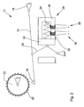
- Fig. 1 shows a schematically illustrated embodiment of the inventive device for controlling a in Fig. 2 illustrated parking brake for a motor vehicle.
- the motor vehicle is in particular an agricultural or industrial utility vehicle, for example a tractor, a harvesting machine, a forage harvester, a self-propelled spraying machine or a construction machine.
- parking brake 12 corresponds to the in EP 1 795 410 B1 illustrated embodiment. Accordingly, this includes a locking arm 14 which is pivotally mounted within an attachable to a vehicle transmission carrier housing 16.
- the locking arm 14 has a locking pawl 18, which can be brought under the influence of a spring-biased biasing force in such a manner in a toothing 20 of an output gear 22 of the vehicle transmission, that rotation of the output gear 22 and thus a unwanted movement of the motor vehicle is prevented.
- an electromagnetic actuator 24 is provided which includes a fixed to the carrier housing 16 magnetic core 26 in which a cooperating with a knee joint assembly 28 armature 30 is arranged for actuating the locking arm 14.
- a first coil 32 wound around the magnetic core 26 serves to generate a magnetic field.
- the armature 30 acts upon application of the magnetic field to the knee joint assembly 28 such that the locking arm 14 is displaced against the biasing force in a disengaged, the toothing 20 of the output gear 22 releasing position.
- a second coil 34 for redundant unlocking the parking brake 12 is present. This is also wound around the magnetic core 26 of the electromagnetic actuator 24.
- the electromagnetic actuator 24 for redundant unlocking the parking brake 12 a first coil 32 comprehensive first electrical adjusting means 36 and a second coil 34 comprehensive second electric actuating means 38 on.
- first operating device 40 and a second operating device 42 are provided, wherein these are arranged within a driver's cab encompassed by the motor vehicle.
- An engageable in at least one neutral, park or driving position, with the vehicle transmission in communication standing speed selector lever 44 is a common part of both
- the vehicle transmission is designed in the present case as "Infinitely Variable Transmission” (IVT), in which a hydrostatically or electrically driven transmission branch with a plurality of mechanically reversible planetary gears cooperates such that the transmission ratio of the Can continuously adjust the vehicle transmission.
- IVT Intelligent Variable Transmission
- the first operating device 40 has a parking position of the speed selector lever 44 indexing first position sensor 46 and a neutral position of the speed selector lever 44 indexing second position sensor 48.
- the position sensors 46 and 48 are designed as Hall sensors.
- a component moving along with the step selector lever 44 carries one or more permanent magnets which are arranged such that the Hall sensors are subjected to a magnetic field strength that is uniquely related to the instantaneous position of the step selector lever 44.
- Each of the Hall sensors generates position information in the form of a voltage signal dependent on the respective magnetic field strength.
- the voltage signals provided by the two position sensors 46 and 48 are then fed to a first control unit 50 and compared by the latter for determining and subsequently verifying the instantaneous position of the speed selector lever 44.
- the position information of the first and second position sensors 46 and 48 are redundantly transmitted via a bus connection 52 to the first control unit 50.
- a bus connection 52 In the present case, this is a CAN data bus present in the motor vehicle. More specifically, the transmission of the position information generated by the two position sensors 46 and 48 to the first control unit 50 on the one hand directly and on the other hand after prior conversion by an intermediate CAN driver 54, so that by comparing the transmitted information on different ways position information incorrect information transfer between the two Position sensors 46 and 48 and the first control unit 50 can be detected.
- a first wheel speed sensor 56 is used to detect the current state of motion of the motor vehicle.
- the first wheel speed sensor 56 transmits to the first control unit 50 rotational speed information relating to the wheel speed present at a first wheel axle of the motor vehicle.
- the second operating device 42 has a parking position and / or neutral position of the speed selector lever 44 indexing third position sensor 58, by means of which a redundant detection of the current position of the speed selector lever 44 takes place.
- the third position sensor 58 is a microswitch that is actuated when the speed selector lever 44 moves out of the parking position and generates position information in the form of a corresponding changeover signal which is fed to a second control unit 60 for evaluation.
- the second operating device 42 comprises in addition to the speed selector lever 44 cooperating with a transmission clutch and / or a vehicle brake system operating pedal 62, wherein a Actual operating state of the operating pedal 62 detecting actuator 64 is provided.
- the actuator 64 is a designed as a potentiometer variable resistor, by means of which a driver-side deflection of the operating pedal 62 is detected and converted into an actuating information in the form of a corresponding control signal, which is supplied to the second control unit 60 for evaluation.
- a lock-up switch 66 accommodated in a vehicle fuse box is provided.
- the bridging switch 66 connected to the second control unit 60 has a contact base 68 and a contact bridge 70 that can be attached by hand to the contact base 68 in different positions.
- a second wheel speed sensor 72 is used for the redundant detection of the current state of motion of the motor vehicle.
- the second wheel speed sensor 72 transmits to the second control unit 60 rotational speed information relating to the wheel speed present at a second wheel axle of the motor vehicle.
- the first and second operating devices 40 and 42 for the redundant control of the first and second electrical actuating means 36 and 38 are assigned independent control units 50 and 60.
- two independent control paths 74 and 76 are provided for actuating the parking brake 12, wherein the first electric actuating means 36 is controlled by the first control unit 50 and the second electrical actuating means 38 by the second control unit 60.
- the two control units 50 and 60 communicate with each other here for the purpose of mutual function monitoring via the bus connection 52. If a faulty operation of one of the two control units 50 and 60 is detected, the corresponding error message is output to the driver, for example by means of a display unit located in the driver's cab of the motor vehicle.
- the operating devices 40 and 42, the control units 50 and 60 and / or the electrical adjusting means 36 and 38 are fed from independent power supply branches 78 and 80.
- Each of the power supply branches 78 and 80 is for this purpose associated with its own voltage stabilizing circuit 82 and 84, wherein the voltage stabilizing circuits 82 and 84 in turn are supplied from the vehicle battery 86 with electrical energy.
- an auxiliary power connection 88 accessible from the outside is provided via which the second control unit 60 can be supplied with power together with the second control device 42 or the second electrical control device 38 in the event of an inadequate state of charge of the vehicle battery 86.
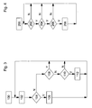
- Fig. 3 shows a flowchart that represents a method for unlocking the parking brake.
- the periodically running in the first control unit 50 process is started in an initialization step 100.
- the first control unit 50 determines the current position of the speed selector lever 44 by evaluating the position information provided by the first and second position sensors 46 and 48.
- the vehicle transmission is formed as with respect to its gear ratio infinitely variable IVT.
- the speed selector lever 44 is used for travel absorption, i. to carry out a forward or reverse drive, starting from the parking position into the neutral position and from there to the corresponding driving position.
- a second step 104 the result of the evaluation of the position information carried out in the first step 102 is that the speed selector lever 44 is within a predetermined range Dead time is moved out of the parking position and spent in the neutral position, it is concluded that there is a desire Entriegelungsdozenses and the parking brake 12 is offset by appropriate control of the first electrical actuating means 36 in a third step 106 in the disengaged position.
- step 104 If, on the other hand, it is determined in the second step 104 that the dead time is exceeded or the speed selector lever 44 is not moved out of the parking position, then in a fourth step 108 it is checked whether the parking brake 12 is in the engaged position. If this is the case, the method returns to the first step 102. Otherwise, in a fifth step 110, the state of motion of the motor vehicle is determined, which takes place by evaluating the speed information provided by the first wheel speed sensor 56 and the speed information provided by the second wheel speed sensor 72 via the bus connection 52.
- the parking brake 12 is displaced from the disengaged to the engaged position in a sixth step 112. Otherwise, the method returns immediately to the first step 102.
- a similar procedure in the locking of the parking brake 12 may also be provided for the case that the speed selector lever 44 in addition to the neutral position has a "power zero" position, which allows a coasting of the motor vehicle to a standstill.
- the parking lock 12 after Reaching the standstill and after subsequent expiration of a predetermined safety time from the disengaged shifted into the engaged position.
- an unlocking of the parking brake 12 in the manner described above is not possible, for example, due to a defect of the first operating device 40, in particular of this encompassed position sensor 46 and 48, and the first control unit 50 and / or the first electrical actuating means 36.
- the method described below allows an emergency release of the parking brake 12.
- Fig. 4 shows a flowchart that represents a method for emergency unlocking the parking brake.
- the periodically running in the second control unit 60 method is started only when the parking brake 12 is in a manually selectable emergency unlocking mode.
- the selection of the emergency unlocking mode is carried out on the bypass switch 66 by attaching the contact bridge 70 in a dedicated position.
- the second control unit 60 checks, in a first step 202 following an initialization step 200, by evaluating the actuating information provided by the actuating transmitter 64 or the position information provided by the third magnetic encoder 58, if the operating pedal 62 is in unactuated state or the speed selector lever 44 is in the park position. If both are the case, then a second step 204 is continued in which it is checked by evaluation of the actuating information provided by the actuator 64, whether the driver 62 deflects the operating pedal while remaining in the parking position speed selector lever 44 within a predetermined dead time. Otherwise, the method returns to the first step 202.
- the second control unit 60 recognizes the presence of the operating sequence of the operating pedal 62 or the speed selector lever 44 which has been checked in the second step 204, then in a third step 206, by evaluating the position information provided by the third position sensor 58, it is determined whether the speed selector lever 44 is within a predetermined dead time is moved from the parking position to the neutral position. If this is the case, then the second control unit 60 concludes the presence of an emergency unlocking request and the parking lock 12 is displaced into the disengaged position by corresponding activation of the second electric actuating means 38 in a fourth step 208. Otherwise, the drive of the second electric actuating means 38 is omitted, and the method returns to the first step 202.
- the second control unit 60 concludes the presence of an emergency unlocking request if, by evaluating a position information provided by the third position sensor 58 in conjunction with an actuating information provided by the actuator 64, that the speed selector lever 44 is at the same time present driver-side deflection of the operating pedal 62nd from the park to the Neutral position is spent.
- the second operating device 42 is to be actuated while maintaining a predetermined operating sequence in the sense of an "unlocking code" to be entered. In this way, an inadvertent or accidental emergency release of the parking brake 12 by the driver can be safely prevented.
- the device according to the invention for controlling a parking brake for a motor vehicle thus has a first operating device and at least one control unit, wherein the at least one control unit sets the parking lock in a disengaged position upon detection of an unlocking request at the first operating device by driving a first electrical actuating means.
- the at least one control unit redundant the parking brake upon detection of a present at a second operating device Notentriegelungsdozenses by driving one of the first electrical actuating means independent second electric actuator in the disengaged position.
Landscapes
- Engineering & Computer Science (AREA)
- Mechanical Engineering (AREA)
- General Engineering & Computer Science (AREA)
- Transportation (AREA)
- Regulating Braking Force (AREA)
- Braking Elements And Transmission Devices (AREA)
- Gear-Shifting Mechanisms (AREA)
Claims (16)
- Dispositif de commande d'un frein de stationnement pour un véhicule automobile, comprenant un premier organe de manoeuvre (40) et au moins une unité de commande (50, 60), ladite unité de commande (50) amenant le frein de stationnement (12) dans une position désaccouplée en commandant un premier moyen de positionnement électrique (36) en cas de détection d'un souhait de déverrouillage présent au niveau du premier organe de manoeuvre (40), caractérisé en ce que ladite unité de commande (60) déplace le frein de stationnement (12) dans la position désaccouplée de manière redondante en cas de détection d'un souhait de déverrouillage d'urgence présent au niveau d'un deuxième organe de manoeuvre (42) en commandant un deuxième moyen de positionnement électrique (38) indépendant du premier moyen de positionnement électrique (36).
- Dispositif selon la revendication 1, caractérisé en ce qu'une borne électrique auxiliaire (88) accessible depuis l'extérieur est prévue sur le véhicule automobile, par le biais de laquelle il est possible d'alimenter électriquement ladite unité de commande (60) conjointement avec le deuxième organe de manoeuvre (42) et/ou le deuxième moyen de positionnement électrique (38).
- Dispositif selon la revendication 1 ou 2, caractérisé en ce que le premier et/ou le deuxième organe de manoeuvre (40, 42) comprend un levier de sélection de palier de marche (44) qui peut être amené au moins dans une position neutre, de stationnement ou de marche et qui interagit avec une boîte de vitesses de véhicule, au moins un codeur de position (46, 48, 58) qui indice la position momentanée du levier de sélection de palier de marche (44) étant prévu.
- Dispositif selon l'une des revendications 1 à 3, caractérisé en ce que ladite unité de commande (50) déduit la présence d'un souhait de déverrouillage lorsqu'il résulte d'une information de position fournie par le codeur de position (46, 48) que le levier de sélection de palier de marche (44) est amené de la position de stationnement à la position neutre.
- Dispositif selon l'une des revendications 1 à 4, caractérisé en ce que le premier organe de manoeuvre (40) présente au moins un premier codeur de position (46) qui indice la position de stationnement du levier de sélection de palier de marche (44) et un deuxième codeur de position (48) qui indice la position neutre du levier de sélection de palier de marche (44), ladite unité de commande (50) comparant entre elles les informations de position fournies par les deux codeurs de position (46, 48) pour vérifier la position momentanée du levier de sélection de palier de marche (44).
- Dispositif selon l'une des revendications 1 à 5, caractérisé en ce que ladite unité de commande (60) déduit la présence d'un souhait de déverrouillage d'urgence lorsque le deuxième organe de manoeuvre (42) est actionné en observant une séquence de manoeuvre prédéfinie.
- Dispositif selon l'une des revendications 1 à 6, caractérisé en ce que le deuxième organe de manoeuvre (42) comprend une pédale de manoeuvre (62) qui interagit avec un accouplement de boîte de vitesses et/ou un circuit de freinage de véhicule, au moins un codeur d'actionnement (64) qui détecte un état d'actionnement momentané de la pédale de manoeuvre (62) étant prévu.
- Dispositif selon l'une des revendications 1 à 7, caractérisé en ce que le deuxième organe de manoeuvre (42) présente un troisième codeur de position (58) qui indice au moins la position de stationnement et/ou neutre du levier de sélection de palier de marche (44), ladite unité de commande (60) déduisant la présence d'un souhait de déverrouillage d'urgence lorsqu'il résulte d'une information de position fournie par le troisième codeur de position (58), combinée avec une information d'actionnement fournie par le codeur d'actionnement (64), que le levier de sélection de palier de marche (44) est amené de la position de stationnement à la position neutre avec actionnement simultané par le conducteur de la pédale de manoeuvre (62).
- Dispositif selon l'une des revendications 1 à 8, caractérisé en ce que ladite unité de commande (60) amène exclusivement le frein de stationnement (12) en position désaccouplée si celui-ci se trouve dans un mode de déverrouillage d'urgence pouvant être sélectionné manuellement.
- Dispositif selon l'une des revendications 1 à 9, caractérisé en ce que les informations de position du premier et du deuxième codeur de position (46, 48) sont transmises de manière redondante à ladite unité de commande (50) par le biais d'une liaison par bus (52), notamment par le biais d'un bus de données CAN présent dans le véhicule automobile.
- Dispositif selon l'une des revendications 1 à 10, caractérisé en ce que le premier et le deuxième organe de manoeuvre (40, 42) sont associées à des unités de commande (50, 60) indépendantes l'une de l'autre pour la commande redondante du premier et du deuxième moyen de positionnement électrique (36, 38).
- Dispositif selon l'une des revendications 1 à 11, caractérisé en ce que les unités de commande (50, 60) communiquent entre elles par le biais d'une liaison par bus (52), notamment par le biais d'un bus de données CAN présent dans le véhicule automobile.
- Dispositif selon l'une des revendications 1 à 12, caractérisé en ce que les organes de manoeuvre (40, 42), les unités de commande (50, 60) et/ou les moyens de positionnement électriques (36, 38) sont alimentés à partir d'au moins deux branches d'alimentation électrique (78, 80) indépendantes l'une de l'autre.
- Dispositif selon l'une des revendications 1 à 13, caractérisé en ce qu'il est prévu au moins un capteur de vitesse de rotation de roue (56, 72) pour détecter l'état de mouvement momentané du véhicule automobile, ladite unité de commande (50) n'amenant le frein de stationnement (12) de la position désaccouplée à la position engagée que s'il résulte d'une information de vitesse de rotation fournie par ledit capteur de vitesse de rotation de roue (56, 72) que le véhicule se trouve à l'arrêt.
- Dispositif selon l'une des revendications 1 à 14, caractérisé en ce plusieurs capteurs de vitesse de rotation de roue (56, 72) sont prévus, ladite unité de commande (50) comparant entre elles les informations de vitesse de rotation fournies par les capteurs de vitesse de rotation de roue (56, 72) en vue de leur vérification réciproque.
- Véhicule automobile, notamment véhicule utilitaire agricole ou industriel, équipé d'un dispositif (10) selon l'une des revendications 1 à 15.
Priority Applications (1)
| Application Number | Priority Date | Filing Date | Title |
|---|---|---|---|
| PL11154377T PL2361812T3 (pl) | 2010-02-17 | 2011-02-14 | Urządzenie do sterowania blokadą postojową dla pojazdu mechanicznego |
Applications Claiming Priority (1)
| Application Number | Priority Date | Filing Date | Title |
|---|---|---|---|
| DE102010002020A DE102010002020A1 (de) | 2010-02-17 | 2010-02-17 | Vorrichtung zur Steuerung einer Parksperre für ein Kraftfahrzeug |
Publications (2)
| Publication Number | Publication Date |
|---|---|
| EP2361812A1 EP2361812A1 (fr) | 2011-08-31 |
| EP2361812B1 true EP2361812B1 (fr) | 2012-11-14 |
Family
ID=44073092
Family Applications (1)
| Application Number | Title | Priority Date | Filing Date |
|---|---|---|---|
| EP11154377A Active EP2361812B1 (fr) | 2010-02-17 | 2011-02-14 | Dispositif de commande d'un frein de stationnement pour un véhicule automobile |
Country Status (5)
| Country | Link |
|---|---|
| US (1) | US20110202246A1 (fr) |
| EP (1) | EP2361812B1 (fr) |
| DE (1) | DE102010002020A1 (fr) |
| ES (1) | ES2399608T3 (fr) |
| PL (1) | PL2361812T3 (fr) |
Cited By (1)
| Publication number | Priority date | Publication date | Assignee | Title |
|---|---|---|---|---|
| DE102015222624A1 (de) | 2015-11-17 | 2017-05-18 | Audi Ag | Verfahren und Überwachungsvorrichtung zum Betreiben eines Kraftfahrzeugs |
Families Citing this family (17)
| Publication number | Priority date | Publication date | Assignee | Title |
|---|---|---|---|---|
| JP5316550B2 (ja) * | 2011-01-05 | 2013-10-16 | 株式会社デンソー | 後方視界支援システム |
| GB2494196B (en) * | 2011-09-05 | 2013-12-11 | Land Rover Uk Ltd | Transmission having a park pawl which is engaged after a predetermined delay |
| DE102012009000A1 (de) * | 2012-05-04 | 2013-11-07 | Bomag Gmbh | Bedienelement einer Baumaschine |
| DE102012010562B4 (de) | 2012-05-26 | 2013-12-24 | Audi Ag | Feststellbremsensystem für ein Fahrzeug |
| DE102013004936A1 (de) * | 2013-03-22 | 2014-09-25 | Dynapac Gmbh | Verfahren zum Bremsen eines selbstfahrenden Straßenfertigers oder Beschickers sowie Bremsanlage für einen selbstfahrenden Straßenfertiger oder Beschicker |
| JP6313152B2 (ja) * | 2014-07-18 | 2018-04-18 | Ntn株式会社 | 電動ブレーキ装置 |
| US9242648B1 (en) * | 2014-09-05 | 2016-01-26 | Caterpillar Inc. | Boosting parking brake drive-through torque |
| DE102015224708A1 (de) * | 2015-03-02 | 2016-09-08 | Continental Teves Ag & Co. Ohg | Steuergerät und Verfahren für ein Kraftfahrzeugbremssystem |
| CN106671963B (zh) * | 2017-01-16 | 2023-09-15 | 四川省客车制造有限责任公司 | 电控型双保险驻车制动系统及包含该系统的车辆 |
| DE102017201982A1 (de) * | 2017-02-08 | 2018-08-09 | Robert Bosch Gmbh | Bremsmotor-Steuergerät und Bremssystem für ein Fahrzeug mit einem elektrischen Bremsmotor |
| DE102017209314A1 (de) * | 2017-06-01 | 2018-12-06 | Robert Bosch Gmbh | Verfahren zum Betreiben einer Feststellbremse und Steuereinheit zum Betreiben einer Feststellbremse |
| CN112109690B (zh) * | 2019-07-17 | 2022-06-21 | 上汽通用五菱汽车股份有限公司 | 自动驻车控制方法、装置及计算机可读存储介质 |
| CN112628397A (zh) * | 2019-09-24 | 2021-04-09 | 上海汽车集团股份有限公司 | 一种故障处理方法及装置 |
| WO2022133744A1 (fr) * | 2020-12-22 | 2022-06-30 | 华为技术有限公司 | Système de frein de stationnement de véhicule automobile, véhicule automobile et procédé de commande associé |
| CN113428124A (zh) * | 2021-07-16 | 2021-09-24 | 中汽创智科技有限公司 | 一种冗余的电子驻车系统及其控制方法 |
| US11984794B2 (en) | 2021-10-08 | 2024-05-14 | Dana Heavy Vehicle Systems Group, Llc | Cooling and lubrication system for an electric motor and gearbox assembly |
| FR3140923B1 (fr) * | 2022-10-12 | 2024-08-30 | Psa Automobiles Sa | Vehicule automobile comprenant un systeme de deblocage d’un actionneur de blocage en stationnement, procede et programme sur la base d’un tel vehicule |
Family Cites Families (77)
| Publication number | Priority date | Publication date | Assignee | Title |
|---|---|---|---|---|
| US1908907A (en) * | 1931-11-16 | 1933-05-16 | David R Lessler | Combined gear shift and parking brake operating device |
| DE1755280B1 (de) * | 1968-04-20 | 1971-08-26 | Teldix Gmbh | Sensor fuer ein antiblockierregelsystem fuer kraftfahrzeug bremsen |
| US3952837A (en) * | 1974-11-01 | 1976-04-27 | Armor Elevator Company | Signaling system for an elevator |
| US4802562A (en) * | 1986-03-17 | 1989-02-07 | Nippondenso Co., Ltd. | Electronically controlled braking system without a master cylinder |
| US5004077A (en) * | 1989-09-13 | 1991-04-02 | Orscheln Co. | Electromechanical parking brake system |
| US5032812A (en) * | 1990-03-01 | 1991-07-16 | Automatic Switch Company | Solenoid actuator having a magnetic flux sensor |
| US5497093A (en) * | 1994-05-02 | 1996-03-05 | General Motors Corporation | Method and apparatus for diagnosing a twin-coil, bi-stable, magnetically latched solenoid |
| US5443132A (en) * | 1994-05-25 | 1995-08-22 | Orscheln Co. | Magnetic latch mechanism and method particularly for brakes |
| US5699883A (en) * | 1996-12-12 | 1997-12-23 | Stromag, Inc. | Spring-applied dual coil brake |
| DE19751431A1 (de) * | 1997-11-20 | 1999-07-15 | Itt Mfg Enterprises Inc | Elektromechanische Feststellbremse |
| US6702405B1 (en) * | 1998-03-31 | 2004-03-09 | Continental Teves Ag & Co., Ohg | Electric parking brake |
| US6545852B1 (en) * | 1998-10-07 | 2003-04-08 | Ormanco | System and method for controlling an electromagnetic device |
| DE19858543A1 (de) * | 1998-12-18 | 2000-06-21 | Zahnradfabrik Friedrichshafen | Steuereinrichtung für ein automatisches Kraftfahrzeug-Getriebe |
| US6406102B1 (en) * | 1999-02-24 | 2002-06-18 | Orscheln Management Co. | Electrically operated parking brake control system |
| DE19920095C1 (de) * | 1999-05-03 | 2000-08-17 | Bayerische Motoren Werke Ag | Automatisches Getriebe mit einer Parksperre |
| DE19931345A1 (de) * | 1999-06-10 | 2000-12-14 | Continental Teves Ag & Co Ohg | Vorrichtung sowie Verfahren für die fahrsituationsabhängige Betätigung einer Bremsanlage eines Kraftfahrzeuges |
| JP3575357B2 (ja) * | 1999-11-25 | 2004-10-13 | 日産自動車株式会社 | 自動変速機のパークロック装置 |
| DE10015782A1 (de) * | 2000-03-30 | 2002-01-03 | Zahnradfabrik Friedrichshafen | Parksperren-System für ein Kraftfahrzeug-Getriebe |
| DE10015781A1 (de) * | 2000-03-30 | 2001-10-04 | Zahnradfabrik Friedrichshafen | Parksperrensystem für ein Kraftfahrzeug-Getriebe |
| DE10037565A1 (de) * | 2000-08-02 | 2002-04-04 | Zahnradfabrik Friedrichshafen | Parksperre, insbesondere für ein Kraftfahrzeuggetriebe |
| DE10049307B4 (de) * | 2000-10-04 | 2013-01-31 | Volkswagen Ag | Sensorik-System für die Steuereinrichtung eines automatisch schaltbaren Getriebes |
| DE10052261A1 (de) | 2000-10-19 | 2002-05-02 | Deere & Co | Steuereinrichtung für die Parksperre eines Kraftfahrzeugs |
| DE10052260A1 (de) * | 2000-10-19 | 2002-06-13 | Deere & Co | Steuereinrichtung für die Parksperre eines Kraftfahrzeugs |
| DE10052259B4 (de) * | 2000-10-19 | 2009-10-15 | Deere & Company, Moline | Notentriegelungseinrichtung für die Parksperre eines Kraftfahrzeugs |
| JP2002257235A (ja) * | 2001-03-01 | 2002-09-11 | Tokai Rika Co Ltd | パーキングロック解除装置 |
| DE10128430B4 (de) * | 2001-06-12 | 2006-09-28 | Zf Friedrichshafen Ag | Parksperren-System |
| JP2003034240A (ja) * | 2001-07-25 | 2003-02-04 | Honda Motor Co Ltd | 車両の制動制御装置 |
| DE10140164A1 (de) * | 2001-08-22 | 2003-03-13 | Zf Lemfoerder Metallwaren Ag | Steuereinheit für die Gang- oder Schaltprogrammwahl eines automatischen Kraftfahrzeuggetriebes |
| US6676564B2 (en) * | 2002-01-18 | 2004-01-13 | Saia-Burgess Inc. | Brake-shift lever interlock unit |
| DE10212038B4 (de) * | 2002-03-19 | 2011-06-16 | Zf Friedrichshafen Ag | Parksperre |
| DE10223880B4 (de) * | 2002-05-29 | 2004-06-17 | Robert Bosch Gmbh | Verfahren zur gegenseitigen Überwachung von Komponenten eines dezentral verteilten Rechnersystems |
| FR2841199B1 (fr) * | 2002-06-20 | 2004-08-27 | Renault Sa | Dispositif et procede de desserrage automatique du frein de parking automatique au demarrage |
| DE50302913D1 (de) * | 2002-09-17 | 2006-05-18 | Continental Teves Ag & Co Ohg | Hydraulische fahrzeugbremse |
| US6905181B2 (en) * | 2002-10-22 | 2005-06-14 | Honda Motor Co., Ltd. | Electric parking brake system |
| ATE396353T1 (de) * | 2003-03-26 | 2008-06-15 | Luk Lamellen & Kupplungsbau | Vorrichtung und verfahren zur steuerung eines parksperren-haltemagneten eines kraftfahrzeuggetriebes |
| DE10320608B4 (de) * | 2003-05-08 | 2005-08-11 | Knorr-Bremse Systeme für Nutzfahrzeuge GmbH | Bremsanlage für Fahrzeuge, insbesondere Nutzfahrzeuge mit mindestens zwei separaten elektronischen Bremssteuerkreisen |
| US7096108B2 (en) * | 2003-09-26 | 2006-08-22 | Haldex Brake Products Ab | Brake system with distributed electronic control units incorporating failsafe mode |
| US7359786B2 (en) * | 2003-09-29 | 2008-04-15 | Haldex Brake Products Ab | Control and power supply network for vehicle braking system |
| US20060157563A1 (en) * | 2004-06-17 | 2006-07-20 | Marshall David A | Smart card systems in connection with transportation services |
| DE102004043416A1 (de) * | 2004-09-08 | 2006-03-30 | Zf Friedrichshafen Ag | Fahrzeuggetriebe mit einer Parksperre und Verfahren zur Steuerung desselben |
| JP2006264384A (ja) * | 2005-03-22 | 2006-10-05 | Toyota Motor Corp | 電動パーキングブレーキ装置 |
| DE102005014242A1 (de) * | 2005-03-30 | 2006-10-05 | Robert Bosch Gmbh | Feststellbremse mit Notlösealgorithmus |
| JP4664749B2 (ja) * | 2005-06-28 | 2011-04-06 | 本田技研工業株式会社 | 車両用ブレーキ装置 |
| US8220877B2 (en) * | 2005-08-08 | 2012-07-17 | Fuji Jukogyo Kabushiki Kaisha | Electric parking brake system |
| GB0518133D0 (en) * | 2005-09-06 | 2005-10-12 | Haldex Brake Products Ltd | Braking system |
| DE102005044254A1 (de) * | 2005-09-15 | 2007-03-29 | Zf Friedrichshafen Ag | Betätigungseinrichtung mit Zusatzschaltelement |
| WO2007050407A1 (fr) * | 2005-10-21 | 2007-05-03 | Deere & Company | Systemes et procedes de commutation entre des mode de conduite autonome et manuel d'un vehicule |
| DE102005057794A1 (de) | 2005-12-03 | 2007-06-06 | Deere & Company, Moline | Vorrichtung zur Betätigung einer Parkbremse |
| DE102006011207A1 (de) * | 2006-03-02 | 2007-09-06 | Getrag Getriebe- Und Zahnradfabrik Hermann Hagenmeyer Gmbh & Cie Kg | Sensoranordnung und Schaltanordnung |
| DE102006016497B4 (de) * | 2006-04-07 | 2013-11-28 | FICO CABLES S.A. Technological Centre Pujol & Tarragó | Betätigungssystem für eine Feststellbremse |
| DE102006026736A1 (de) * | 2006-06-08 | 2007-12-13 | Siemens Ag | Verfahren und Steueranordnung zum gesteuerten Lösen zumindest einer elektrischen Parkbremse eines Fahrzeuges |
| DE102006041011A1 (de) * | 2006-08-31 | 2008-03-06 | Wabco Gmbh | Ventileinheit für eine elektropneumatische Bremssteuerungseinrichtung |
| DE102006048558A1 (de) * | 2006-10-13 | 2008-04-17 | Deere & Company, Moline | Feststellbremse zum Feststellen mindestens eines drehbar gelagerten Bauteils gegenüber einem Gehäuse |
| DE102006055570B4 (de) * | 2006-11-24 | 2010-05-06 | Knorr-Bremse Systeme für Nutzfahrzeuge GmbH | Feststellbremsvorrichtung mit einer Feststellbremse-Notlöseeinrichtung |
| DE102007011359A1 (de) * | 2007-03-07 | 2008-09-11 | Zf Friedrichshafen Ag | Betätigungseinrichtung mit Wählhebelaktuator |
| US20090020976A1 (en) * | 2007-07-16 | 2009-01-22 | The Pullman Company | Bushing having high axial spring rate and method of manufacturing |
| DE102007036259A1 (de) * | 2007-08-02 | 2009-02-05 | Robert Bosch Gmbh | Bremssystem für ein Fahrzeug und ein Verfahren zum Betreiben eines Bremssystems für ein Fahrzeug |
| JP4389985B2 (ja) * | 2007-09-04 | 2009-12-24 | トヨタ自動車株式会社 | 状態切替要素の作動装置、自動変速機のレンジ切替装置、ならびにパーキング装置 |
| JP4952493B2 (ja) * | 2007-10-10 | 2012-06-13 | 株式会社アドヴィックス | 駐車ブレーキ制御装置 |
| DE102008051350A1 (de) * | 2007-10-27 | 2009-04-30 | Continental Teves Ag & Co. Ohg | Kombinierte Fahrzeugbremse mit elektromechanisch betätigbarer Feststellbremse |
| US7926889B2 (en) * | 2007-10-29 | 2011-04-19 | Textron Innovations Inc. | Hill hold for an electric vehicle |
| DE102008006398A1 (de) * | 2008-01-28 | 2009-07-30 | Zf Friedrichshafen Ag | Notentriegelungseinrichtung für Parksperre |
| GB0802212D0 (en) * | 2008-02-06 | 2008-03-12 | Meritor Heavy Vehicle Braking | A brake system and method |
| JP5104370B2 (ja) * | 2008-02-13 | 2012-12-19 | 株式会社アドヴィックス | 駐車ブレーキ制御装置 |
| DE102008009882A1 (de) * | 2008-02-19 | 2009-08-20 | Wabco Gmbh | Feststellbremse für ein Fahrzeug und Verfahren zum Betrieb der Feststellbremse |
| DE102008034915A1 (de) * | 2008-07-26 | 2010-01-28 | Bayerische Motoren Werke Aktiengesellschaft | Parkbremse mit einer Einrichtung zum Lösen |
| KR101037028B1 (ko) * | 2008-09-30 | 2011-05-25 | 현대자동차주식회사 | 접촉식 하중센서가 구비된 전자식 주차 브레이크 유닛 |
| DE102008043249B3 (de) * | 2008-10-29 | 2010-01-28 | Zf Friedrichshafen Ag | Betätigungseinrichtung für Parksperre |
| US8265846B2 (en) * | 2009-03-27 | 2012-09-11 | GM Global Technology Operations LLC | Method for operating a vehicle brake system |
| KR101302612B1 (ko) * | 2009-07-29 | 2013-09-03 | 주식회사 만도 | 전자식 주차 브레이크 시스템 및 그 제어 방법 |
| JP5240364B2 (ja) * | 2009-08-27 | 2013-07-17 | トヨタ自動車株式会社 | 車両用パーキングロック装置 |
| WO2011046136A1 (fr) * | 2009-10-13 | 2011-04-21 | ボッシュ株式会社 | Dispositif de régulation de freinage |
| KR20120063774A (ko) * | 2010-12-08 | 2012-06-18 | 현대자동차주식회사 | 하이브리드 차량용 파킹 시스템 |
| DE102010055859A1 (de) * | 2010-12-22 | 2012-06-28 | Audi Ag | Vorrichtung zum Betätigen einer Parksperre |
| GB2486669A (en) * | 2010-12-22 | 2012-06-27 | Land Rover Uk Ltd | Brake control to ensure automatic service brake effort does not exceed parking brake effort |
| US8550426B2 (en) * | 2011-01-19 | 2013-10-08 | Bendix Commercial Vehicle Systems Llc | Two step park brake release |
| FR2981910B1 (fr) * | 2011-10-26 | 2013-12-27 | Eurocopter France | Atterrisseur, aeronef et procede |
-
2010
- 2010-02-17 DE DE102010002020A patent/DE102010002020A1/de not_active Withdrawn
-
2011
- 2011-01-31 US US13/017,156 patent/US20110202246A1/en not_active Abandoned
- 2011-02-14 ES ES11154377T patent/ES2399608T3/es active Active
- 2011-02-14 PL PL11154377T patent/PL2361812T3/pl unknown
- 2011-02-14 EP EP11154377A patent/EP2361812B1/fr active Active
Cited By (4)
| Publication number | Priority date | Publication date | Assignee | Title |
|---|---|---|---|---|
| DE102015222624A1 (de) | 2015-11-17 | 2017-05-18 | Audi Ag | Verfahren und Überwachungsvorrichtung zum Betreiben eines Kraftfahrzeugs |
| WO2017084917A2 (fr) | 2015-11-17 | 2017-05-26 | Audi Ag | Procédé et dispositif de surveillance permettant de faire fonctionner un véhicule automobile |
| WO2017084917A3 (fr) * | 2015-11-17 | 2017-08-17 | Audi Ag | Procédé et dispositif de surveillance permettant de faire fonctionner un véhicule automobile |
| DE102015222624B4 (de) * | 2015-11-17 | 2020-02-06 | Audi Ag | Verfahren und Überwachungsvorrichtung zum Betreiben eines Kraftfahrzeugs |
Also Published As
| Publication number | Publication date |
|---|---|
| DE102010002020A1 (de) | 2011-08-18 |
| US20110202246A1 (en) | 2011-08-18 |
| EP2361812A1 (fr) | 2011-08-31 |
| PL2361812T3 (pl) | 2013-04-30 |
| ES2399608T3 (es) | 2013-04-02 |
Similar Documents
| Publication | Publication Date | Title |
|---|---|---|
| EP2361812B1 (fr) | Dispositif de commande d'un frein de stationnement pour un véhicule automobile | |
| EP0972667B1 (fr) | Véhicule avec transmission automatique à commande électronique et freinage de stationnement commandé par force externe | |
| DE112008000048B4 (de) | Fahrzeugsteuervorrichtung | |
| DE4129919C2 (de) | Feststellbremsanlage für Kraftwagen, insbesondere Personenkraftwagen | |
| DE102006025168A1 (de) | Fahrzeugsteuerungssystem | |
| WO2018041386A1 (fr) | Système de freinage pneumatique à commande électronique dans un véhicule utilitaire, et procédé de commande électronique d'un système de freinage pneumatique dans un véhicule utilitaire | |
| DE112018006002T5 (de) | Fahrzeugsteuervorrichtung | |
| EP2001717A1 (fr) | Frein de stationnement électrique muni d'un élément de commande pour basculer dans un mode de service | |
| DE102014105715A1 (de) | Verbesserte Sichtbarkeit der Position einer Fahrzeugzündung | |
| DE102007058143A1 (de) | System und Verfahren zum Einstellen eines Radeinschlagwinkels eines Rades eines Kraftfahrzeugs | |
| EP1125067B1 (fr) | Procede et dispositif pour la surveillance du mouvement d'un actionneur | |
| EP1972514B1 (fr) | Véhicule automobile doté d'un système X-by-wire et procédé de fonctionnement d'un système X-by-wire d'un véhicule automobile | |
| DE69605088T2 (de) | Steuerung für einen elektrisch betätigten Gangschaltmechanismus | |
| DE19910048A1 (de) | Verfahren und Vorrichtung zur Überwachung der Bewegung eines Aktuators | |
| DE19714786C1 (de) | Lenkeinrichtung | |
| DE4231821A1 (de) | Steuereinrichtung für Kraftfahrzeuge | |
| WO2000057088A1 (fr) | Dispositif de commande destine a des boites de vitesses de vehicules | |
| DE19814657A1 (de) | Steuer- und/oder Regelvorrichtung für eine elektrische Feststellbremseinrichtung von Fahrzeugen | |
| DE102018217473B4 (de) | Parksperrenmechanismus für ein Fahrzeug | |
| EP3735545B1 (fr) | Procédé de commande d'un véhicule automobile avec verrouillage de stationnement | |
| DE102012219533A1 (de) | Bremsanlage für Kraftfahrzeuge | |
| EP0975872B1 (fr) | Systeme d'antidemarrage pour un vehicule a moteur equipe d'une boite de vitesses automatique | |
| EP1564096B1 (fr) | La vérification du fonctionnement correcte d'un frein de stationnement par l'évaluation de la vitesse de rotation d'un roue | |
| DE102005019864B4 (de) | Elektrische Lenkungsverriegelung | |
| EP4264089A1 (fr) | Actionneur, et dispositif de mise en prise d'un verrou de stationnement d'une transmission automatique de véhicule automobile comportant ledit actionneur, et véhicule automobile équipé de celui-ci |
Legal Events
| Date | Code | Title | Description |
|---|---|---|---|
| PUAI | Public reference made under article 153(3) epc to a published international application that has entered the european phase |
Free format text: ORIGINAL CODE: 0009012 |
|
| AK | Designated contracting states |
Kind code of ref document: A1 Designated state(s): AL AT BE BG CH CY CZ DE DK EE ES FI FR GB GR HR HU IE IS IT LI LT LU LV MC MK MT NL NO PL PT RO RS SE SI SK SM TR |
|
| AX | Request for extension of the european patent |
Extension state: BA ME |
|
| 17P | Request for examination filed |
Effective date: 20120229 |
|
| RIC1 | Information provided on ipc code assigned before grant |
Ipc: F16H 63/48 20060101ALI20120402BHEP Ipc: B60T 7/04 20060101ALI20120402BHEP Ipc: B60T 7/08 20060101ALI20120402BHEP Ipc: B60T 13/66 20060101ALI20120402BHEP Ipc: B60T 13/74 20060101ALI20120402BHEP Ipc: F16H 61/22 20060101ALI20120402BHEP Ipc: B60T 7/12 20060101ALI20120402BHEP Ipc: B60T 1/00 20060101AFI20120402BHEP Ipc: F16D 65/14 20060101ALI20120402BHEP Ipc: B60T 17/18 20060101ALI20120402BHEP |
|
| GRAP | Despatch of communication of intention to grant a patent |
Free format text: ORIGINAL CODE: EPIDOSNIGR1 |
|
| RIN1 | Information on inventor provided before grant (corrected) |
Inventor name: THIEME, MICHAEL Inventor name: LINDSAY, RYAN Inventor name: MUENCH, PETER |
|
| GRAS | Grant fee paid |
Free format text: ORIGINAL CODE: EPIDOSNIGR3 |
|
| GRAA | (expected) grant |
Free format text: ORIGINAL CODE: 0009210 |
|
| AK | Designated contracting states |
Kind code of ref document: B1 Designated state(s): AL AT BE BG CH CY CZ DE DK EE ES FI FR GB GR HR HU IE IS IT LI LT LU LV MC MK MT NL NO PL PT RO RS SE SI SK SM TR |
|
| REG | Reference to a national code |
Ref country code: GB Ref legal event code: FG4D Free format text: NOT ENGLISH |
|
| REG | Reference to a national code |
Ref country code: CH Ref legal event code: EP Ref country code: AT Ref legal event code: REF Ref document number: 583798 Country of ref document: AT Kind code of ref document: T Effective date: 20121115 |
|
| REG | Reference to a national code |
Ref country code: IE Ref legal event code: FG4D Free format text: LANGUAGE OF EP DOCUMENT: GERMAN |
|
| REG | Reference to a national code |
Ref country code: DE Ref legal event code: R096 Ref document number: 502011000200 Country of ref document: DE Effective date: 20130110 |
|
| REG | Reference to a national code |
Ref country code: SE Ref legal event code: TRGR |
|
| REG | Reference to a national code |
Ref country code: ES Ref legal event code: FG2A Ref document number: 2399608 Country of ref document: ES Kind code of ref document: T3 Effective date: 20130402 |
|
| REG | Reference to a national code |
Ref country code: NL Ref legal event code: VDEP Effective date: 20121114 |
|
| REG | Reference to a national code |
Ref country code: LT Ref legal event code: MG4D |
|
| PG25 | Lapsed in a contracting state [announced via postgrant information from national office to epo] |
Ref country code: NO Free format text: LAPSE BECAUSE OF FAILURE TO SUBMIT A TRANSLATION OF THE DESCRIPTION OR TO PAY THE FEE WITHIN THE PRESCRIBED TIME-LIMIT Effective date: 20130214 Ref country code: HR Free format text: LAPSE BECAUSE OF FAILURE TO SUBMIT A TRANSLATION OF THE DESCRIPTION OR TO PAY THE FEE WITHIN THE PRESCRIBED TIME-LIMIT Effective date: 20121114 Ref country code: LT Free format text: LAPSE BECAUSE OF FAILURE TO SUBMIT A TRANSLATION OF THE DESCRIPTION OR TO PAY THE FEE WITHIN THE PRESCRIBED TIME-LIMIT Effective date: 20121114 |
|
| REG | Reference to a national code |
Ref country code: PL Ref legal event code: T3 |
|
| PG25 | Lapsed in a contracting state [announced via postgrant information from national office to epo] |
Ref country code: LV Free format text: LAPSE BECAUSE OF FAILURE TO SUBMIT A TRANSLATION OF THE DESCRIPTION OR TO PAY THE FEE WITHIN THE PRESCRIBED TIME-LIMIT Effective date: 20121114 Ref country code: GR Free format text: LAPSE BECAUSE OF FAILURE TO SUBMIT A TRANSLATION OF THE DESCRIPTION OR TO PAY THE FEE WITHIN THE PRESCRIBED TIME-LIMIT Effective date: 20130215 Ref country code: PT Free format text: LAPSE BECAUSE OF FAILURE TO SUBMIT A TRANSLATION OF THE DESCRIPTION OR TO PAY THE FEE WITHIN THE PRESCRIBED TIME-LIMIT Effective date: 20130314 Ref country code: SI Free format text: LAPSE BECAUSE OF FAILURE TO SUBMIT A TRANSLATION OF THE DESCRIPTION OR TO PAY THE FEE WITHIN THE PRESCRIBED TIME-LIMIT Effective date: 20121114 |
|
| REG | Reference to a national code |
Ref country code: HU Ref legal event code: AG4A Ref document number: E015652 Country of ref document: HU |
|
| PG25 | Lapsed in a contracting state [announced via postgrant information from national office to epo] |
Ref country code: DK Free format text: LAPSE BECAUSE OF FAILURE TO SUBMIT A TRANSLATION OF THE DESCRIPTION OR TO PAY THE FEE WITHIN THE PRESCRIBED TIME-LIMIT Effective date: 20121114 Ref country code: SK Free format text: LAPSE BECAUSE OF FAILURE TO SUBMIT A TRANSLATION OF THE DESCRIPTION OR TO PAY THE FEE WITHIN THE PRESCRIBED TIME-LIMIT Effective date: 20121114 Ref country code: BG Free format text: LAPSE BECAUSE OF FAILURE TO SUBMIT A TRANSLATION OF THE DESCRIPTION OR TO PAY THE FEE WITHIN THE PRESCRIBED TIME-LIMIT Effective date: 20130214 Ref country code: EE Free format text: LAPSE BECAUSE OF FAILURE TO SUBMIT A TRANSLATION OF THE DESCRIPTION OR TO PAY THE FEE WITHIN THE PRESCRIBED TIME-LIMIT Effective date: 20121114 Ref country code: RS Free format text: LAPSE BECAUSE OF FAILURE TO SUBMIT A TRANSLATION OF THE DESCRIPTION OR TO PAY THE FEE WITHIN THE PRESCRIBED TIME-LIMIT Effective date: 20121114 |
|
| PG25 | Lapsed in a contracting state [announced via postgrant information from national office to epo] |
Ref country code: NL Free format text: LAPSE BECAUSE OF FAILURE TO SUBMIT A TRANSLATION OF THE DESCRIPTION OR TO PAY THE FEE WITHIN THE PRESCRIBED TIME-LIMIT Effective date: 20121114 Ref country code: RO Free format text: LAPSE BECAUSE OF FAILURE TO SUBMIT A TRANSLATION OF THE DESCRIPTION OR TO PAY THE FEE WITHIN THE PRESCRIBED TIME-LIMIT Effective date: 20121114 |
|
| BERE | Be: lapsed |
Owner name: DEERE & CY Effective date: 20130228 |
|
| PLBE | No opposition filed within time limit |
Free format text: ORIGINAL CODE: 0009261 |
|
| STAA | Information on the status of an ep patent application or granted ep patent |
Free format text: STATUS: NO OPPOSITION FILED WITHIN TIME LIMIT |
|
| PG25 | Lapsed in a contracting state [announced via postgrant information from national office to epo] |
Ref country code: MC Free format text: LAPSE BECAUSE OF NON-PAYMENT OF DUE FEES Effective date: 20130228 |
|
| 26N | No opposition filed |
Effective date: 20130815 |
|
| PG25 | Lapsed in a contracting state [announced via postgrant information from national office to epo] |
Ref country code: CY Free format text: LAPSE BECAUSE OF FAILURE TO SUBMIT A TRANSLATION OF THE DESCRIPTION OR TO PAY THE FEE WITHIN THE PRESCRIBED TIME-LIMIT Effective date: 20121114 |
|
| REG | Reference to a national code |
Ref country code: IE Ref legal event code: MM4A |
|
| REG | Reference to a national code |
Ref country code: DE Ref legal event code: R097 Ref document number: 502011000200 Country of ref document: DE Effective date: 20130815 |
|
| PG25 | Lapsed in a contracting state [announced via postgrant information from national office to epo] |
Ref country code: BE Free format text: LAPSE BECAUSE OF NON-PAYMENT OF DUE FEES Effective date: 20130228 Ref country code: IE Free format text: LAPSE BECAUSE OF NON-PAYMENT OF DUE FEES Effective date: 20130214 Ref country code: AL Free format text: LAPSE BECAUSE OF FAILURE TO SUBMIT A TRANSLATION OF THE DESCRIPTION OR TO PAY THE FEE WITHIN THE PRESCRIBED TIME-LIMIT Effective date: 20121114 |
|
| PGFP | Annual fee paid to national office [announced via postgrant information from national office to epo] |
Ref country code: FI Payment date: 20140227 Year of fee payment: 4 Ref country code: CZ Payment date: 20140131 Year of fee payment: 4 Ref country code: SE Payment date: 20140227 Year of fee payment: 4 |
|
| PGFP | Annual fee paid to national office [announced via postgrant information from national office to epo] |
Ref country code: HU Payment date: 20140124 Year of fee payment: 4 Ref country code: IT Payment date: 20140228 Year of fee payment: 4 Ref country code: PL Payment date: 20140121 Year of fee payment: 4 Ref country code: ES Payment date: 20140226 Year of fee payment: 4 |
|
| PG25 | Lapsed in a contracting state [announced via postgrant information from national office to epo] |
Ref country code: MT Free format text: LAPSE BECAUSE OF FAILURE TO SUBMIT A TRANSLATION OF THE DESCRIPTION OR TO PAY THE FEE WITHIN THE PRESCRIBED TIME-LIMIT Effective date: 20121114 |
|
| REG | Reference to a national code |
Ref country code: CH Ref legal event code: PL |
|
| PG25 | Lapsed in a contracting state [announced via postgrant information from national office to epo] |
Ref country code: CH Free format text: LAPSE BECAUSE OF NON-PAYMENT OF DUE FEES Effective date: 20140228 Ref country code: LI Free format text: LAPSE BECAUSE OF NON-PAYMENT OF DUE FEES Effective date: 20140228 |
|
| PG25 | Lapsed in a contracting state [announced via postgrant information from national office to epo] |
Ref country code: SM Free format text: LAPSE BECAUSE OF FAILURE TO SUBMIT A TRANSLATION OF THE DESCRIPTION OR TO PAY THE FEE WITHIN THE PRESCRIBED TIME-LIMIT Effective date: 20121114 |
|
| PG25 | Lapsed in a contracting state [announced via postgrant information from national office to epo] |
Ref country code: TR Free format text: LAPSE BECAUSE OF FAILURE TO SUBMIT A TRANSLATION OF THE DESCRIPTION OR TO PAY THE FEE WITHIN THE PRESCRIBED TIME-LIMIT Effective date: 20121114 |
|
| PG25 | Lapsed in a contracting state [announced via postgrant information from national office to epo] |
Ref country code: LU Free format text: LAPSE BECAUSE OF NON-PAYMENT OF DUE FEES Effective date: 20130214 Ref country code: MK Free format text: LAPSE BECAUSE OF FAILURE TO SUBMIT A TRANSLATION OF THE DESCRIPTION OR TO PAY THE FEE WITHIN THE PRESCRIBED TIME-LIMIT Effective date: 20121114 |
|
| REG | Reference to a national code |
Ref country code: SE Ref legal event code: EUG |
|
| PG25 | Lapsed in a contracting state [announced via postgrant information from national office to epo] |
Ref country code: CZ Free format text: LAPSE BECAUSE OF NON-PAYMENT OF DUE FEES Effective date: 20150214 Ref country code: FI Free format text: LAPSE BECAUSE OF NON-PAYMENT OF DUE FEES Effective date: 20150214 |
|
| PG25 | Lapsed in a contracting state [announced via postgrant information from national office to epo] |
Ref country code: HU Free format text: LAPSE BECAUSE OF NON-PAYMENT OF DUE FEES Effective date: 20150215 Ref country code: SE Free format text: LAPSE BECAUSE OF NON-PAYMENT OF DUE FEES Effective date: 20150215 |
|
| PG25 | Lapsed in a contracting state [announced via postgrant information from national office to epo] |
Ref country code: IT Free format text: LAPSE BECAUSE OF NON-PAYMENT OF DUE FEES Effective date: 20150214 |
|
| REG | Reference to a national code |
Ref country code: FR Ref legal event code: PLFP Year of fee payment: 6 |
|
| REG | Reference to a national code |
Ref country code: ES Ref legal event code: FD2A Effective date: 20160329 |
|
| PG25 | Lapsed in a contracting state [announced via postgrant information from national office to epo] |
Ref country code: ES Free format text: LAPSE BECAUSE OF NON-PAYMENT OF DUE FEES Effective date: 20150215 |
|
| PG25 | Lapsed in a contracting state [announced via postgrant information from national office to epo] |
Ref country code: PL Free format text: LAPSE BECAUSE OF NON-PAYMENT OF DUE FEES Effective date: 20150214 |
|
| PG25 | Lapsed in a contracting state [announced via postgrant information from national office to epo] |
Ref country code: IS Free format text: LAPSE BECAUSE OF FAILURE TO SUBMIT A TRANSLATION OF THE DESCRIPTION OR TO PAY THE FEE WITHIN THE PRESCRIBED TIME-LIMIT Effective date: 20121114 |
|
| REG | Reference to a national code |
Ref country code: FR Ref legal event code: PLFP Year of fee payment: 7 |
|
| REG | Reference to a national code |
Ref country code: AT Ref legal event code: MM01 Ref document number: 583798 Country of ref document: AT Kind code of ref document: T Effective date: 20160214 |
|
| PG25 | Lapsed in a contracting state [announced via postgrant information from national office to epo] |
Ref country code: AT Free format text: LAPSE BECAUSE OF NON-PAYMENT OF DUE FEES Effective date: 20160214 |
|
| REG | Reference to a national code |
Ref country code: FR Ref legal event code: PLFP Year of fee payment: 8 |
|
| PGFP | Annual fee paid to national office [announced via postgrant information from national office to epo] |
Ref country code: DE Payment date: 20240119 Year of fee payment: 14 Ref country code: GB Payment date: 20240227 Year of fee payment: 14 |
|
| PGFP | Annual fee paid to national office [announced via postgrant information from national office to epo] |
Ref country code: FR Payment date: 20240226 Year of fee payment: 14 |