EP2361812B1 - Device for controlling a parking brake for a motor vehicle - Google Patents
Device for controlling a parking brake for a motor vehicle Download PDFInfo
- Publication number
- EP2361812B1 EP2361812B1 EP11154377A EP11154377A EP2361812B1 EP 2361812 B1 EP2361812 B1 EP 2361812B1 EP 11154377 A EP11154377 A EP 11154377A EP 11154377 A EP11154377 A EP 11154377A EP 2361812 B1 EP2361812 B1 EP 2361812B1
- Authority
- EP
- European Patent Office
- Prior art keywords
- control unit
- selector lever
- motor vehicle
- operator control
- parking brake
- Prior art date
- Legal status (The legal status is an assumption and is not a legal conclusion. Google has not performed a legal analysis and makes no representation as to the accuracy of the status listed.)
- Active
Links
Images

Classifications
-
- B—PERFORMING OPERATIONS; TRANSPORTING
- B60—VEHICLES IN GENERAL
- B60T—VEHICLE BRAKE CONTROL SYSTEMS OR PARTS THEREOF; BRAKE CONTROL SYSTEMS OR PARTS THEREOF, IN GENERAL; ARRANGEMENT OF BRAKING ELEMENTS ON VEHICLES IN GENERAL; PORTABLE DEVICES FOR PREVENTING UNWANTED MOVEMENT OF VEHICLES; VEHICLE MODIFICATIONS TO FACILITATE COOLING OF BRAKES
- B60T1/00—Arrangements of braking elements, i.e. of those parts where braking effect occurs specially for vehicles
- B60T1/005—Arrangements of braking elements, i.e. of those parts where braking effect occurs specially for vehicles by locking of wheel or transmission rotation
-
- B—PERFORMING OPERATIONS; TRANSPORTING
- B60—VEHICLES IN GENERAL
- B60T—VEHICLE BRAKE CONTROL SYSTEMS OR PARTS THEREOF; BRAKE CONTROL SYSTEMS OR PARTS THEREOF, IN GENERAL; ARRANGEMENT OF BRAKING ELEMENTS ON VEHICLES IN GENERAL; PORTABLE DEVICES FOR PREVENTING UNWANTED MOVEMENT OF VEHICLES; VEHICLE MODIFICATIONS TO FACILITATE COOLING OF BRAKES
- B60T13/00—Transmitting braking action from initiating means to ultimate brake actuator with power assistance or drive; Brake systems incorporating such transmitting means, e.g. air-pressure brake systems
- B60T13/74—Transmitting braking action from initiating means to ultimate brake actuator with power assistance or drive; Brake systems incorporating such transmitting means, e.g. air-pressure brake systems with electrical assistance or drive
- B60T13/746—Transmitting braking action from initiating means to ultimate brake actuator with power assistance or drive; Brake systems incorporating such transmitting means, e.g. air-pressure brake systems with electrical assistance or drive and mechanical transmission of the braking action
-
- B—PERFORMING OPERATIONS; TRANSPORTING
- B60—VEHICLES IN GENERAL
- B60T—VEHICLE BRAKE CONTROL SYSTEMS OR PARTS THEREOF; BRAKE CONTROL SYSTEMS OR PARTS THEREOF, IN GENERAL; ARRANGEMENT OF BRAKING ELEMENTS ON VEHICLES IN GENERAL; PORTABLE DEVICES FOR PREVENTING UNWANTED MOVEMENT OF VEHICLES; VEHICLE MODIFICATIONS TO FACILITATE COOLING OF BRAKES
- B60T7/00—Brake-action initiating means
- B60T7/02—Brake-action initiating means for personal initiation
- B60T7/04—Brake-action initiating means for personal initiation foot actuated
- B60T7/042—Brake-action initiating means for personal initiation foot actuated by electrical means, e.g. using travel or force sensors
-
- B—PERFORMING OPERATIONS; TRANSPORTING
- B60—VEHICLES IN GENERAL
- B60T—VEHICLE BRAKE CONTROL SYSTEMS OR PARTS THEREOF; BRAKE CONTROL SYSTEMS OR PARTS THEREOF, IN GENERAL; ARRANGEMENT OF BRAKING ELEMENTS ON VEHICLES IN GENERAL; PORTABLE DEVICES FOR PREVENTING UNWANTED MOVEMENT OF VEHICLES; VEHICLE MODIFICATIONS TO FACILITATE COOLING OF BRAKES
- B60T7/00—Brake-action initiating means
- B60T7/02—Brake-action initiating means for personal initiation
- B60T7/08—Brake-action initiating means for personal initiation hand actuated
- B60T7/085—Brake-action initiating means for personal initiation hand actuated by electrical means, e.g. travel, force sensors
-
- F—MECHANICAL ENGINEERING; LIGHTING; HEATING; WEAPONS; BLASTING
- F16—ENGINEERING ELEMENTS AND UNITS; GENERAL MEASURES FOR PRODUCING AND MAINTAINING EFFECTIVE FUNCTIONING OF MACHINES OR INSTALLATIONS; THERMAL INSULATION IN GENERAL
- F16D—COUPLINGS FOR TRANSMITTING ROTATION; CLUTCHES; BRAKES
- F16D63/00—Brakes not otherwise provided for; Brakes combining more than one of the types of groups F16D49/00 - F16D61/00
- F16D63/006—Positive locking brakes
-
- F—MECHANICAL ENGINEERING; LIGHTING; HEATING; WEAPONS; BLASTING
- F16—ENGINEERING ELEMENTS AND UNITS; GENERAL MEASURES FOR PRODUCING AND MAINTAINING EFFECTIVE FUNCTIONING OF MACHINES OR INSTALLATIONS; THERMAL INSULATION IN GENERAL
- F16H—GEARING
- F16H63/00—Control outputs from the control unit to change-speed- or reversing-gearings for conveying rotary motion or to other devices than the final output mechanism
- F16H63/02—Final output mechanisms therefor; Actuating means for the final output mechanisms
- F16H63/30—Constructional features of the final output mechanisms
- F16H63/34—Locking or disabling mechanisms
- F16H63/3416—Parking lock mechanisms or brakes in the transmission
- F16H63/3458—Parking lock mechanisms or brakes in the transmission with electric actuating means, e.g. shift by wire
- F16H63/3475—Parking lock mechanisms or brakes in the transmission with electric actuating means, e.g. shift by wire using solenoids
-
- F—MECHANICAL ENGINEERING; LIGHTING; HEATING; WEAPONS; BLASTING
- F16—ENGINEERING ELEMENTS AND UNITS; GENERAL MEASURES FOR PRODUCING AND MAINTAINING EFFECTIVE FUNCTIONING OF MACHINES OR INSTALLATIONS; THERMAL INSULATION IN GENERAL
- F16H—GEARING
- F16H63/00—Control outputs from the control unit to change-speed- or reversing-gearings for conveying rotary motion or to other devices than the final output mechanism
- F16H63/02—Final output mechanisms therefor; Actuating means for the final output mechanisms
- F16H63/30—Constructional features of the final output mechanisms
- F16H63/34—Locking or disabling mechanisms
- F16H63/3416—Parking lock mechanisms or brakes in the transmission
- F16H63/3491—Emergency release or engagement of parking locks or brakes
-
- F—MECHANICAL ENGINEERING; LIGHTING; HEATING; WEAPONS; BLASTING
- F16—ENGINEERING ELEMENTS AND UNITS; GENERAL MEASURES FOR PRODUCING AND MAINTAINING EFFECTIVE FUNCTIONING OF MACHINES OR INSTALLATIONS; THERMAL INSULATION IN GENERAL
- F16H—GEARING
- F16H63/00—Control outputs from the control unit to change-speed- or reversing-gearings for conveying rotary motion or to other devices than the final output mechanism
- F16H63/40—Control outputs from the control unit to change-speed- or reversing-gearings for conveying rotary motion or to other devices than the final output mechanism comprising signals other than signals for actuating the final output mechanisms
- F16H63/48—Signals to a parking brake or parking lock; Control of parking locks or brakes being part of the transmission
- F16H63/483—Circuits for controlling engagement of parking locks or brakes
-
- F—MECHANICAL ENGINEERING; LIGHTING; HEATING; WEAPONS; BLASTING
- F16—ENGINEERING ELEMENTS AND UNITS; GENERAL MEASURES FOR PRODUCING AND MAINTAINING EFFECTIVE FUNCTIONING OF MACHINES OR INSTALLATIONS; THERMAL INSULATION IN GENERAL
- F16D—COUPLINGS FOR TRANSMITTING ROTATION; CLUTCHES; BRAKES
- F16D2121/00—Type of actuator operation force
- F16D2121/18—Electric or magnetic
- F16D2121/20—Electric or magnetic using electromagnets
- F16D2121/22—Electric or magnetic using electromagnets for releasing a normally applied brake
-
- F—MECHANICAL ENGINEERING; LIGHTING; HEATING; WEAPONS; BLASTING
- F16—ENGINEERING ELEMENTS AND UNITS; GENERAL MEASURES FOR PRODUCING AND MAINTAINING EFFECTIVE FUNCTIONING OF MACHINES OR INSTALLATIONS; THERMAL INSULATION IN GENERAL
- F16D—COUPLINGS FOR TRANSMITTING ROTATION; CLUTCHES; BRAKES
- F16D2123/00—Multiple operation forces
Definitions
- the invention relates to a device for controlling a parking brake for a motor vehicle, with a first operating device and at least one control unit, wherein the at least one control unit puts the parking brake in a disengaged position upon detection of a present on the first operating device Entriegelungsdozenses by driving a first electrical actuating means.
- Such a device for controlling a parking brake in a motor vehicle for example, from the DE 100 52 261 A1 out.
- the known device has an actuatable by a drive means actuator in the form of a hydraulic piston, by means of which a locking device encompassed by the parking brake offset against a restoring force in a disengaged position and can be unlocked in this way.
- the drive means is preferably designed as an actuatable by a control unit electromagnetic hydraulic valve, wherein the control unit derives the desire to unlock the parking brake from a sensory detected position of the driver to be operated control lever.
- a mechanical emergency control device is provided, which makes it possible to move the locking device by means of a suspension on a clutch pedal of the motor vehicle Bowden cable in the disengaged position and to lock in this.
- the known device Due to the additional mechanical components required for the emergency operating device, the known device has a comparatively complicated construction.
- the device according to the invention for controlling a parking brake for a motor vehicle comprises a first operating device and at least one control unit, wherein the at least one control unit sets the parking lock in a disengaged position upon detection of an unlocking request at the first operating device by activation of a first electrical actuating means.
- the at least one control unit redundant the parking brake upon detection of a present at a second operating device Notentriegelungsdozenses by driving one of the first electrical actuating means independent second electric actuator in the disengaged position.
- the two electric adjusting means can be a structural component and the same electrically operated parking brake.
- An additional mechanical emergency operating device is dispensable in this case, since the probability that the at least one control unit or the second operating device and / or the second electrical actuating means likewise has a defect is negligibly small.
- the parking lock preferably corresponds to the in EP 1 795 410 B1 illustrated embodiment. Accordingly, this includes a locking arm which is pivotally mounted within an attachable to a vehicle transmission carrier housing.
- the locking arm has a locking pawl, which can be brought under the influence of a spring-biased biasing force in such a toothing of an output gear of the vehicle transmission in engagement, that rotation of the output gear and thus an undesirable movement of the vehicle is prevented.
- an electromagnetic actuator is provided which comprises a fixed to the carrier housing magnetic core in which a co-operating with a knee joint assembly armature for actuating the locking arm is arranged. A wound around the magnetic core first coil is used to generate a magnetic field.
- the armature acts on the knee joint arrangement in such a way that the blocking arm is displaced counter to the pretensioning force into a disengaged position which releases the teeth of the output gearwheel.
- a second coil for redundant unlocking the parking brake is available. This is also wound around the magnetic core of the electromagnetic actuator.
- the electromagnetic actuator for redundant unlocking the parking brake on a first coil comprehensive first electrical actuating means and a second coil comprehensive second electrical actuating means.
- the motor vehicle is provided from an externally accessible auxiliary power connection through which the at least one control unit together with the second operating device and / or the second electrical actuating means can be supplied with power.
- the first and / or second operating device comprises a speed selector lever communicating with a vehicle transmission in at least one neutral, parking or driving position, at least one position transmitter indicating the instantaneous position of the speed selector lever being provided.
- the vehicle transmission can be designed, for example, as "Infinitely Variable Transmission” (IVT), in which a hydrostatically or electrically driven transmission branch interacts with a plurality of mechanically reversible planetary gears such that the transmission ratio of the vehicle transmission can be infinitely adjusted.
- IVTT Intelligent Variable Transmission
- the parking brake is automatically offset after reaching standstill and subsequent expiry of a predetermined safety time from the disengaged to the engaged position.
- the first operating device may have at least one first position indicator indicating the parking position of the drive level selector lever and a second position transmitter indicating the neutral position of the drive level selector lever, wherein the at least one control unit compares the position information provided by the two position sensors for verifying the current position of the speed selector lever.
- the position sensors are designed in particular as Hall sensors.
- a co-moving with the speed selector lever component carries one or more permanent magnets, which are arranged such that the Hall sensors are acted upon by the current position of the selector lever in a unique manner related magnetic field strength.
- Each of the Hall sensors generates position information in the form of a dependent of the respective magnetic field strength voltage signal, wherein by evaluating the respective magnitude or course of the voltage signals and by comparing their temporal relationship to each other a reliable determination of the current position of the speed selector lever is possible.
- the at least one control unit preferably concludes the presence of an emergency unlocking request when the second operating device is actuated in compliance with a predetermined operating sequence in the sense of an "unlocking code" to be entered. In this way, an inadvertent or accidental emergency release the parking brake by the driver can be safely prevented.
- the second operating device may comprise a cooperating with a transmission clutch and / or a vehicle brake control pedal, wherein at least one of the current operating state of the operating pedal is detected detecting actuator.
- the operating pedal can be used for opening or closing a transmission clutch or for controlling wheel brake devices cooperating with vehicle wheels.
- the actuating transmitter is a variable resistor formed as a potentiometer, by means of which a driver-side deflection of the operating pedal can be detected and converted into actuating information in the form of a corresponding actuating signal.
- the second operating device has a third position indicator indicating at least the parking and / or neutral position of the drive level selection lever, wherein the at least one control unit concludes the presence of an emergency unlocking request if, by evaluating position information provided by the third position sensor in conjunction with a control information provided by the actuator results in that the speed selector lever is spent at the same time present driver-side operation of the operating pedal of the parking in the neutral position.
- the third position sensor a redundant detection of the current position of the speed selector lever.
- the third position sensor is a microswitch which is actuated when the speed selector lever is moved out of the parking position and thereby generates position information in the form of a corresponding changeover signal.
- the at least one control unit puts the parking brake in the disengaged position only when it is in a manually selectable emergency unlocking mode.
- the emergency unlock mode may be selected, for example, via a lock-up switch housed in a vehicle fuse box.
- the bridging switch has a contact base and a contact bridge which can be plugged by hand into the contact base in different positions, wherein the selection of the emergency unlocking mode is carried out by attaching the contact bridge in a specially provided position.
- the position information of the first and second position sensor is preferably transmitted redundantly via a bus connection, in particular via a CAN data bus present in the motor vehicle, to the at least one control unit. More specifically, the transmission is from the two position encoders generated position information to the at least one control unit on the one hand directly and on the other hand after prior conversion by an intermediate CAN driver. By comparing the position information transmitted in different ways, an erroneous transfer of information between the two position sensors and the at least one control unit can be detected.
- the first and second operating device for redundant control of the first and second electrical actuating means are assigned independent control units.
- two independent control paths for actuating the parking brake are provided, wherein the first electrical actuating means is controlled by the first control unit and the second electrical actuating means by the second control unit.
- the two control units can communicate with one another via a bus connection, in particular via a CAN data bus present in the motor vehicle.
- a bus connection in particular via a CAN data bus present in the motor vehicle.
- This allows a mutual function monitoring of the control units. If a faulty operation of one of the two control units is detected, then the output of a corresponding error message to the driver can take place, for example by means of a display unit located in the driver's cab of the motor vehicle.
- the operating devices, the control units and / or the electrical actuating means of at least two independent power supply branches be fed.
- Each of the power supply branches is assigned for this purpose a separate voltage stabilization circuit, wherein the voltage stabilization circuits in turn are supplied from the vehicle battery with electrical energy.
- At least one RaFieresensor is provided for detecting the current state of motion of the motor vehicle, wherein the at least one control unit, the parking brake exclusively from the disengaged in the engaged position, if due to a from the at least one wheel speed sensor provided speed information shows that the motor vehicle is at a standstill.
- a plurality of such wheel speed sensors are provided, wherein the at least one control unit compares the speed information provided by the wheel speed sensors with each other for the purpose of their mutual verification.
- the at least one control unit compares the speed information provided by the wheel speed sensors with each other for the purpose of their mutual verification. In this case, even with a faulty operation of one of the wheel speed sensors, a reliable statement about the current state of motion of the motor vehicle, in particular about its standstill, can be made.
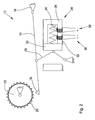
- Fig. 1 shows a schematically illustrated embodiment of the inventive device for controlling a in Fig. 2 illustrated parking brake for a motor vehicle.
- the motor vehicle is in particular an agricultural or industrial utility vehicle, for example a tractor, a harvesting machine, a forage harvester, a self-propelled spraying machine or a construction machine.
- parking brake 12 corresponds to the in EP 1 795 410 B1 illustrated embodiment. Accordingly, this includes a locking arm 14 which is pivotally mounted within an attachable to a vehicle transmission carrier housing 16.
- the locking arm 14 has a locking pawl 18, which can be brought under the influence of a spring-biased biasing force in such a manner in a toothing 20 of an output gear 22 of the vehicle transmission, that rotation of the output gear 22 and thus a unwanted movement of the motor vehicle is prevented.
- an electromagnetic actuator 24 is provided which includes a fixed to the carrier housing 16 magnetic core 26 in which a cooperating with a knee joint assembly 28 armature 30 is arranged for actuating the locking arm 14.
- a first coil 32 wound around the magnetic core 26 serves to generate a magnetic field.
- the armature 30 acts upon application of the magnetic field to the knee joint assembly 28 such that the locking arm 14 is displaced against the biasing force in a disengaged, the toothing 20 of the output gear 22 releasing position.
- a second coil 34 for redundant unlocking the parking brake 12 is present. This is also wound around the magnetic core 26 of the electromagnetic actuator 24.
- the electromagnetic actuator 24 for redundant unlocking the parking brake 12 a first coil 32 comprehensive first electrical adjusting means 36 and a second coil 34 comprehensive second electric actuating means 38 on.
- first operating device 40 and a second operating device 42 are provided, wherein these are arranged within a driver's cab encompassed by the motor vehicle.
- An engageable in at least one neutral, park or driving position, with the vehicle transmission in communication standing speed selector lever 44 is a common part of both
- the vehicle transmission is designed in the present case as "Infinitely Variable Transmission” (IVT), in which a hydrostatically or electrically driven transmission branch with a plurality of mechanically reversible planetary gears cooperates such that the transmission ratio of the Can continuously adjust the vehicle transmission.
- IVT Intelligent Variable Transmission
- the first operating device 40 has a parking position of the speed selector lever 44 indexing first position sensor 46 and a neutral position of the speed selector lever 44 indexing second position sensor 48.
- the position sensors 46 and 48 are designed as Hall sensors.
- a component moving along with the step selector lever 44 carries one or more permanent magnets which are arranged such that the Hall sensors are subjected to a magnetic field strength that is uniquely related to the instantaneous position of the step selector lever 44.
- Each of the Hall sensors generates position information in the form of a voltage signal dependent on the respective magnetic field strength.
- the voltage signals provided by the two position sensors 46 and 48 are then fed to a first control unit 50 and compared by the latter for determining and subsequently verifying the instantaneous position of the speed selector lever 44.
- the position information of the first and second position sensors 46 and 48 are redundantly transmitted via a bus connection 52 to the first control unit 50.
- a bus connection 52 In the present case, this is a CAN data bus present in the motor vehicle. More specifically, the transmission of the position information generated by the two position sensors 46 and 48 to the first control unit 50 on the one hand directly and on the other hand after prior conversion by an intermediate CAN driver 54, so that by comparing the transmitted information on different ways position information incorrect information transfer between the two Position sensors 46 and 48 and the first control unit 50 can be detected.
- a first wheel speed sensor 56 is used to detect the current state of motion of the motor vehicle.
- the first wheel speed sensor 56 transmits to the first control unit 50 rotational speed information relating to the wheel speed present at a first wheel axle of the motor vehicle.
- the second operating device 42 has a parking position and / or neutral position of the speed selector lever 44 indexing third position sensor 58, by means of which a redundant detection of the current position of the speed selector lever 44 takes place.
- the third position sensor 58 is a microswitch that is actuated when the speed selector lever 44 moves out of the parking position and generates position information in the form of a corresponding changeover signal which is fed to a second control unit 60 for evaluation.
- the second operating device 42 comprises in addition to the speed selector lever 44 cooperating with a transmission clutch and / or a vehicle brake system operating pedal 62, wherein a Actual operating state of the operating pedal 62 detecting actuator 64 is provided.
- the actuator 64 is a designed as a potentiometer variable resistor, by means of which a driver-side deflection of the operating pedal 62 is detected and converted into an actuating information in the form of a corresponding control signal, which is supplied to the second control unit 60 for evaluation.
- a lock-up switch 66 accommodated in a vehicle fuse box is provided.
- the bridging switch 66 connected to the second control unit 60 has a contact base 68 and a contact bridge 70 that can be attached by hand to the contact base 68 in different positions.
- a second wheel speed sensor 72 is used for the redundant detection of the current state of motion of the motor vehicle.
- the second wheel speed sensor 72 transmits to the second control unit 60 rotational speed information relating to the wheel speed present at a second wheel axle of the motor vehicle.
- the first and second operating devices 40 and 42 for the redundant control of the first and second electrical actuating means 36 and 38 are assigned independent control units 50 and 60.
- two independent control paths 74 and 76 are provided for actuating the parking brake 12, wherein the first electric actuating means 36 is controlled by the first control unit 50 and the second electrical actuating means 38 by the second control unit 60.
- the two control units 50 and 60 communicate with each other here for the purpose of mutual function monitoring via the bus connection 52. If a faulty operation of one of the two control units 50 and 60 is detected, the corresponding error message is output to the driver, for example by means of a display unit located in the driver's cab of the motor vehicle.
- the operating devices 40 and 42, the control units 50 and 60 and / or the electrical adjusting means 36 and 38 are fed from independent power supply branches 78 and 80.
- Each of the power supply branches 78 and 80 is for this purpose associated with its own voltage stabilizing circuit 82 and 84, wherein the voltage stabilizing circuits 82 and 84 in turn are supplied from the vehicle battery 86 with electrical energy.
- an auxiliary power connection 88 accessible from the outside is provided via which the second control unit 60 can be supplied with power together with the second control device 42 or the second electrical control device 38 in the event of an inadequate state of charge of the vehicle battery 86.
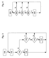
- Fig. 3 shows a flowchart that represents a method for unlocking the parking brake.
- the periodically running in the first control unit 50 process is started in an initialization step 100.
- the first control unit 50 determines the current position of the speed selector lever 44 by evaluating the position information provided by the first and second position sensors 46 and 48.
- the vehicle transmission is formed as with respect to its gear ratio infinitely variable IVT.
- the speed selector lever 44 is used for travel absorption, i. to carry out a forward or reverse drive, starting from the parking position into the neutral position and from there to the corresponding driving position.
- a second step 104 the result of the evaluation of the position information carried out in the first step 102 is that the speed selector lever 44 is within a predetermined range Dead time is moved out of the parking position and spent in the neutral position, it is concluded that there is a desire Entriegelungsdozenses and the parking brake 12 is offset by appropriate control of the first electrical actuating means 36 in a third step 106 in the disengaged position.
- step 104 If, on the other hand, it is determined in the second step 104 that the dead time is exceeded or the speed selector lever 44 is not moved out of the parking position, then in a fourth step 108 it is checked whether the parking brake 12 is in the engaged position. If this is the case, the method returns to the first step 102. Otherwise, in a fifth step 110, the state of motion of the motor vehicle is determined, which takes place by evaluating the speed information provided by the first wheel speed sensor 56 and the speed information provided by the second wheel speed sensor 72 via the bus connection 52.
- the parking brake 12 is displaced from the disengaged to the engaged position in a sixth step 112. Otherwise, the method returns immediately to the first step 102.
- a similar procedure in the locking of the parking brake 12 may also be provided for the case that the speed selector lever 44 in addition to the neutral position has a "power zero" position, which allows a coasting of the motor vehicle to a standstill.
- the parking lock 12 after Reaching the standstill and after subsequent expiration of a predetermined safety time from the disengaged shifted into the engaged position.
- an unlocking of the parking brake 12 in the manner described above is not possible, for example, due to a defect of the first operating device 40, in particular of this encompassed position sensor 46 and 48, and the first control unit 50 and / or the first electrical actuating means 36.
- the method described below allows an emergency release of the parking brake 12.
- Fig. 4 shows a flowchart that represents a method for emergency unlocking the parking brake.
- the periodically running in the second control unit 60 method is started only when the parking brake 12 is in a manually selectable emergency unlocking mode.
- the selection of the emergency unlocking mode is carried out on the bypass switch 66 by attaching the contact bridge 70 in a dedicated position.
- the second control unit 60 checks, in a first step 202 following an initialization step 200, by evaluating the actuating information provided by the actuating transmitter 64 or the position information provided by the third magnetic encoder 58, if the operating pedal 62 is in unactuated state or the speed selector lever 44 is in the park position. If both are the case, then a second step 204 is continued in which it is checked by evaluation of the actuating information provided by the actuator 64, whether the driver 62 deflects the operating pedal while remaining in the parking position speed selector lever 44 within a predetermined dead time. Otherwise, the method returns to the first step 202.
- the second control unit 60 recognizes the presence of the operating sequence of the operating pedal 62 or the speed selector lever 44 which has been checked in the second step 204, then in a third step 206, by evaluating the position information provided by the third position sensor 58, it is determined whether the speed selector lever 44 is within a predetermined dead time is moved from the parking position to the neutral position. If this is the case, then the second control unit 60 concludes the presence of an emergency unlocking request and the parking lock 12 is displaced into the disengaged position by corresponding activation of the second electric actuating means 38 in a fourth step 208. Otherwise, the drive of the second electric actuating means 38 is omitted, and the method returns to the first step 202.
- the second control unit 60 concludes the presence of an emergency unlocking request if, by evaluating a position information provided by the third position sensor 58 in conjunction with an actuating information provided by the actuator 64, that the speed selector lever 44 is at the same time present driver-side deflection of the operating pedal 62nd from the park to the Neutral position is spent.
- the second operating device 42 is to be actuated while maintaining a predetermined operating sequence in the sense of an "unlocking code" to be entered. In this way, an inadvertent or accidental emergency release of the parking brake 12 by the driver can be safely prevented.
- the device according to the invention for controlling a parking brake for a motor vehicle thus has a first operating device and at least one control unit, wherein the at least one control unit sets the parking lock in a disengaged position upon detection of an unlocking request at the first operating device by driving a first electrical actuating means.
- the at least one control unit redundant the parking brake upon detection of a present at a second operating device Notentriegelungsdozenses by driving one of the first electrical actuating means independent second electric actuator in the disengaged position.
Description
Die Erfindung betrifft eine Vorrichtung zur Steuerung einer Parksperre für ein Kraftfahrzeug, mit einer ersten Bedieneinrichtung und zumindest einer Steuereinheit, wobei die zumindest eine Steuereinheit die Parksperre bei Erkennung eines an der ersten Bedieneinrichtung vorliegenden Entriegelungswunsches durch Ansteuerung eines ersten elektrischen Stellmittels in eine ausgerückte Position versetzt.The invention relates to a device for controlling a parking brake for a motor vehicle, with a first operating device and at least one control unit, wherein the at least one control unit puts the parking brake in a disengaged position upon detection of a present on the first operating device Entriegelungswunsches by driving a first electrical actuating means.
Eine derartige Vorrichtung zur Steuerung einer Parksperre in einem Kraftfahrzeug geht beispielsweise aus der
Aufgrund der für die Notbetätigungseinrichtung erforderlichen zusätzlichen mechanischen Komponenten ist die bekannte Vorrichtung vergleichsweise aufwendig aufgebaut.Due to the additional mechanical components required for the emergency operating device, the known device has a comparatively complicated construction.
Es ist daher Aufgabe der vorliegenden Erfindung, eine Vorrichtung der eingangs genannten Art dahingehend weiterzubilden, dass diese das Vorhandensein einer zusätzlichen mechanischen Notbetätigungseinrichtung entbehrlich macht.It is therefore an object of the present invention to develop a device of the type mentioned in such a way that it makes the presence of an additional mechanical emergency control dispensable.
Diese Aufgabe wird durch eine Vorrichtung mit den Merkmalen des Patentanspruchs 1 gelöst.This object is achieved by a device having the features of patent claim 1.
Die erfindungsgemäße Vorrichtung zur Steuerung einer Parksperre für ein Kraftfahrzeug umfasst eine erste Bedieneinrichtung und zumindest eine Steuereinheit, wobei die zumindest eine Steuereinheit die Parksperre bei Erkennung eines an der ersten Bedieneinrichtung vorliegenden Entriegelungswunsches durch Ansteuerung eines ersten elektrischen Stellmittels in eine ausgerückte Position versetzt. Um die Parksperre zumindest bei einem Defekt der ersten Bedieneinrichtung und/oder des ersten elektrischen Stellmittels entriegeln zu können, ist ferner vorgesehen, dass die zumindest eine Steuereinheit die Parksperre redundant bei Erkennung eines an einer zweiten Bedieneinrichtung vorliegenden Notentriegelungswunsches durch Ansteuerung eines von dem ersten elektrischen Stellmittel unabhängigen zweiten elektrischen Stellmittels in die ausgerückte Position versetzt. Die beiden elektrischen Stellmittel können hierbei baulicher Bestandteil ein und der selben elektrisch betätigbaren Parksperre sein. Eine zusätzliche mechanische Notbetätigungseinrichtung ist in diesem Fall entbehrlich, da die Wahrscheinlichkeit, dass die zumindest eine Steuereinheit bzw. die zweite Bedieneinrichtung und/oder das zweite elektrische Stellmittel gleichfalls einen Defekt aufweist, vernachlässigbar gering ist.The device according to the invention for controlling a parking brake for a motor vehicle comprises a first operating device and at least one control unit, wherein the at least one control unit sets the parking lock in a disengaged position upon detection of an unlocking request at the first operating device by activation of a first electrical actuating means. In order to unlock the parking lock at least in case of a defect of the first operating device and / or the first electrical actuating means, it is further provided that the at least one control unit redundant the parking brake upon detection of a present at a second operating device Notentriegelungswunsches by driving one of the first electrical actuating means independent second electric actuator in the disengaged position. The two electric adjusting means can be a structural component and the same electrically operated parking brake. An additional mechanical emergency operating device is dispensable in this case, since the probability that the at least one control unit or the second operating device and / or the second electrical actuating means likewise has a defect is negligibly small.
Die Parksperre entspricht vorzugsweise der in
Vorteilhafte Ausgestaltungen der Vorrichtung gehen aus den Unteransprüchen hervor.Advantageous embodiments of the device will become apparent from the dependent claims.
Um eine Notentriegelung der Parksperre auch im Falle eines Ausfalls der fahrzeugeigenen Stromversorgung zu ermöglichen, beispielsweise infolge eines unzulänglichen Ladezustands der Fahrzeugbatterie, ist es von Vorteil, wenn an dem Kraftfahrzeug ein von außen zugänglicher Hilfsstromanschluss vorgesehen ist, über den sich die zumindest eine Steuereinheit gemeinsam mit der zweiten Bedieneinrichtung und/oder dem zweiten elektrischen Stellmittel mit Strom versorgen lässt.In order to enable an emergency unlocking the parking brake even in the event of failure of the vehicle's power supply, for example due to an insufficient state of charge of the vehicle battery, it is advantageous if the motor vehicle is provided from an externally accessible auxiliary power connection through which the at least one control unit together with the second operating device and / or the second electrical actuating means can be supplied with power.
Die erste und/oder zweite Bedieneinrichtung umfasst insbesondere einen in zumindest eine Neutral-, Park- oder Fahrstellung verbringbaren, mit einem Fahrzeuggetriebe in Verbindung stehenden Fahrstufenwahlhebel, wobei zumindest ein die momentane Stellung des Fahrstufenwahlhebels indizierender Positionsgeber vorgesehen ist. Das Fahrzeuggetriebe kann beispielsweise als "Infinitely Variable Transmission" (IVT) ausgebildet sein, bei dem ein hydrostatisch oder elektrisch angetriebener Getriebezweig mit einer Vielzahl von mechanisch umschaltbaren Planetengetrieben derart zusammenwirkt, dass sich das Übersetzungsverhältnis des Fahrzeuggetriebes stufenlos verstellen lässt.In particular, the first and / or second operating device comprises a speed selector lever communicating with a vehicle transmission in at least one neutral, parking or driving position, at least one position transmitter indicating the instantaneous position of the speed selector lever being provided. The vehicle transmission can be designed, for example, as "Infinitely Variable Transmission" (IVT), in which a hydrostatically or electrically driven transmission branch interacts with a plurality of mechanically reversible planetary gears such that the transmission ratio of the vehicle transmission can be infinitely adjusted.
Bei einem derartigen Fahrzeuggetriebe wird der Fahrstufenwahlhebel zur Fahrtaufnahme, d.h. zur Durchführung einer Vorwärts- oder Rückwärtsfahrt ausgehend von der Parkstellung in die Neutralstellung und von dort in die entsprechende Fahrstellung verbracht. Dementsprechend besteht die Möglichkeit, dass die zumindest eine Steuereinheit auf das Vorliegen eines Entriegelungswunsches schließt, wenn sich aufgrund einer von dem Positionsgeber bereitgestellten Positionsinformation ergibt, dass der Fahrstufenwahlhebel vom Fahrer von der Park- in die Neutralstellung verbracht wird.In such a vehicle transmission of the speed selector lever for driving recording, ie spent to carry out a forward or reverse travel starting from the parking position in the neutral position and from there to the corresponding driving position. Accordingly, there is the possibility that the at least one control unit is aware of the presence of a Entriegelungswunsches closes when it is due to a provided by the position sensor position information that the speed selector lever is moved from the parked to the neutral position by the driver.
Zusätzlich zur Neutralstellung kann der Fahrstufenwahlhebel eine "Power Zero"-Stellung aufweisen, die ein Ausrollen des Kraftfahrzeugs in den Stillstand erlaubt, wobei die Parksperre nach Erreichen des Stillstands und nach anschließendem Ablauf einer vorgegebenen Sicherheitszeit selbsttätig aus der ausgerückten in die eingerückte Position versetzt wird.In addition to the neutral position of the speed selector lever may have a "power zero" position, which allows a coasting of the motor vehicle to a stop, the parking brake is automatically offset after reaching standstill and subsequent expiry of a predetermined safety time from the disengaged to the engaged position.
Die erste Bedieneinrichtung kann zumindest einen die Parkstellung des Fahrstufenwahlhebels indizierenden ersten Positionsgeber und einen die Neutralstellung des Fahrstufenwahlhebels indizierenden zweiten Positionsgeber aufweisen, wobei die zumindest eine Steuereinheit die von den beiden Positionsgebern bereitgestellten Positionsinformationen zur Verifizierung der momentanen Stellung des Fahrstufenwahlhebels miteinander vergleicht. Die Positionsgeber sind insbesondere als Hallsensoren ausgebildet. Ein mit dem Fahrstufenwahlhebel mitbewegtes Bauteil trägt einen oder mehrere Permanentmagnete, die derart angeordnet sind, dass die Hallsensoren mit einer von der momentanen Stellung des Fahrstufenwahlhebels in eindeutiger Weise zusammenhängenden Magnetfeldstärke beaufschlagt werden. Jeder der Hallsensoren erzeugt eine Positionsinformation in Gestalt eines von der jeweiligen Magnetfeldstärke abhängigen Spannungssignals, wobei durch Auswertung des jeweiligen Betrags bzw. Verlaufs der Spannungssignale sowie durch Vergleich deren zeitlicher Beziehung zueinander eine verlässliche Ermittlung der momentanen Stellung des Fahrstufenwahlhebels möglich ist.The first operating device may have at least one first position indicator indicating the parking position of the drive level selector lever and a second position transmitter indicating the neutral position of the drive level selector lever, wherein the at least one control unit compares the position information provided by the two position sensors for verifying the current position of the speed selector lever. The position sensors are designed in particular as Hall sensors. A co-moving with the speed selector lever component carries one or more permanent magnets, which are arranged such that the Hall sensors are acted upon by the current position of the selector lever in a unique manner related magnetic field strength. Each of the Hall sensors generates position information in the form of a dependent of the respective magnetic field strength voltage signal, wherein by evaluating the respective magnitude or course of the voltage signals and by comparing their temporal relationship to each other a reliable determination of the current position of the speed selector lever is possible.
Vorzugsweise schließt die zumindest eine Steuereinheit auf das Vorliegen eines Notentriegelungswunsches, wenn die zweite Bedieneinrichtung unter Einhaltung einer vorgegebenen Bedienabfolge im Sinne eines einzugebenden "Entriegelungscodes" betätigt wird. Auf diese Weise kann einer unbeabsichtigten bzw. versehentlichen Notentriegelung der Parksperre seitens des Fahrers sicher vorgebeugt werden.The at least one control unit preferably concludes the presence of an emergency unlocking request when the second operating device is actuated in compliance with a predetermined operating sequence in the sense of an "unlocking code" to be entered. In this way, an inadvertent or accidental emergency release the parking brake by the driver can be safely prevented.
Insbesondere kann die zweite Bedieneinrichtung ein mit einer Getriebekupplung und/oder einer Fahrzeugbremsanlage zusammenwirkendes Bedienpedal umfassen, wobei zumindest ein den momentanen Betätigungszustand des Bedienpedals erfassender Betätigungsgeber vorgesehen ist. Genauer gesagt kann das Bedienpedal zum Öffnen bzw. Schließen einer Getriebekupplung bzw. zur Ansteuerung von mit Fahrzeugrädern zusammenwirkenden Radbremseinrichtungen dienen. Bei dem Betätigungsgeber handelt es sich beispielsweise um einen als Potentiometer ausgebildeten Stellwiderstand, mittels dessen sich eine fahrerseitige Auslenkung des Bedienpedals erfassen und in eine Betätigungsinformation in Gestalt eines entsprechenden Stellsignals umwandeln lässt.In particular, the second operating device may comprise a cooperating with a transmission clutch and / or a vehicle brake control pedal, wherein at least one of the current operating state of the operating pedal is detected detecting actuator. More specifically, the operating pedal can be used for opening or closing a transmission clutch or for controlling wheel brake devices cooperating with vehicle wheels. By way of example, the actuating transmitter is a variable resistor formed as a potentiometer, by means of which a driver-side deflection of the operating pedal can be detected and converted into actuating information in the form of a corresponding actuating signal.
Des Weiteren besteht die Möglichkeit, dass die zweite Bedieneinrichtung einen zumindest die Park- und/oder Neutralstellung des Fahrstufenwahlhebels indizierenden dritten Positionsgeber aufweist, wobei die zumindest eine Steuereinheit auf das Vorliegen eines Notentriegelungswunsches schließt, wenn sich durch Auswertung einer von dem dritten Positionsgeber bereitgestellten Positionsinformation in Verbindung mit einer von dem Betätigungsgeber bereitgestellten Betätigungsinformation ergibt, dass der Fahrstufenwahlhebel bei zugleich vorliegender fahrerseitiger Betätigung des Bedienpedals von der Park- in die Neutralstellung verbracht wird. Mit anderen Worten erfolgt mittels des dritten Positionsgebers eine redundante Erfassung der momentanen Stellung des Fahrstufenwahlhebels. Bei dem dritten Positionsgeber handelt es sich im einfachsten Fall um einen Mikroschalter, der beim Herausbewegen des Fahrstufenwahlhebels aus der Parkstellung betätigt wird und dabei eine Positionsinformation in Gestalt eines entsprechenden Umschaltsignals erzeugt.Furthermore, there is the possibility that the second operating device has a third position indicator indicating at least the parking and / or neutral position of the drive level selection lever, wherein the at least one control unit concludes the presence of an emergency unlocking request if, by evaluating position information provided by the third position sensor in conjunction with a control information provided by the actuator results in that the speed selector lever is spent at the same time present driver-side operation of the operating pedal of the parking in the neutral position. In other words, by means of the third position sensor, a redundant detection of the current position of the speed selector lever. In the simplest case, the third position sensor is a microswitch which is actuated when the speed selector lever is moved out of the parking position and thereby generates position information in the form of a corresponding changeover signal.
Um eine unbeabsichtigte Notentriegelung auszuschließen, ist es denkbar, dass die zumindest eine Steuereinheit die Parksperre ausschließlich dann in die ausgerückte Position versetzt, wenn sich diese in einem manuell anwählbaren Notentriegelungsmodus befindet. Der Notentriegelungsmodus kann beispielsweise über einen in einem Fahrzeugsicherungskasten untergebrachten Überbrückungsschalter ausgewählt werden. Der Überbrückungsschalter weist insbesondere einen Kontaktsockel sowie eine in unterschiedlichen Positionen auf den Kontaktsockel von Hand aufsteckbare Kontaktbrücke auf, wobei die Auswahl des Notentriegelungsmodus durch Aufstecken der Kontaktbrücke in einer eigens dafür vorgesehenen Position erfolgt.In order to exclude an accidental emergency release, it is conceivable that the at least one control unit puts the parking brake in the disengaged position only when it is in a manually selectable emergency unlocking mode. The emergency unlock mode may be selected, for example, via a lock-up switch housed in a vehicle fuse box. In particular, the bridging switch has a contact base and a contact bridge which can be plugged by hand into the contact base in different positions, wherein the selection of the emergency unlocking mode is carried out by attaching the contact bridge in a specially provided position.
Vorzugsweise werden die Positionsinformationen des ersten und zweiten Positionsgebers redundant über eine Busverbindung, insbesondere über einen in dem Kraftfahrzeug vorhandenen CAN-Datenbus, an die zumindest eine Steuereinheit übertragen. Genauer gesagt erfolgt die Übertragung der von den beiden Positionsgebern erzeugten Positionsinformationen an die zumindest eine Steuereinheit einerseits unmittelbar und andererseits nach vorheriger Umwandlung durch einen zwischengeschalteten CAN-Treiber. Durch Vergleich der auf unterschiedlichen Wegen übermittelten Positionsinformationen kann eine fehlerhafte Informationsübertragung zwischen den beiden Positionsgebern und der zumindest einen Steuereinheit erkannt werden.The position information of the first and second position sensor is preferably transmitted redundantly via a bus connection, in particular via a CAN data bus present in the motor vehicle, to the at least one control unit. More specifically, the transmission is from the two position encoders generated position information to the at least one control unit on the one hand directly and on the other hand after prior conversion by an intermediate CAN driver. By comparing the position information transmitted in different ways, an erroneous transfer of information between the two position sensors and the at least one control unit can be detected.
Im Sinne einer möglichst hohen Ausfallsicherheit der erfindungsgemäßen Vorrichtung sind der ersten und zweiten Bedieneinrichtung zur redundanten Ansteuerung des ersten und zweiten elektrischen Stellmittels voneinander unabhängige Steuereinheiten zugeordnet. Insofern werden zwei voneinander unabhängige Steuerpfade zur Betätigung der Parksperre geschaffen, wobei das erste elektrische Stellmittel von der ersten Steuereinheit und das zweite elektrische Stellmittel von der zweiten Steuereinheit angesteuert wird.In terms of the highest possible reliability of the device according to the invention the first and second operating device for redundant control of the first and second electrical actuating means are assigned independent control units. In this respect, two independent control paths for actuating the parking brake are provided, wherein the first electrical actuating means is controlled by the first control unit and the second electrical actuating means by the second control unit.
Die beiden Steuereinheiten können hierbei über eine Busverbindung, insbesondere über einen in dem Kraftfahrzeug vorhandenen CAN-Datenbus, miteinander kommunizieren. Dies erlaubt eine gegenseitige Funktionsüberwachung der Steuereinheiten. Wird ein fehlerhafter Betrieb einer der beiden Steuereinheiten erkannt, so kann die Ausgabe einer entsprechenden Fehlermeldung an den Fahrer erfolgen, beispielsweise mittels einer in der Fahrerkabine des Kraftfahrzeugs befindlichen Anzeigeeinheit.In this case, the two control units can communicate with one another via a bus connection, in particular via a CAN data bus present in the motor vehicle. This allows a mutual function monitoring of the control units. If a faulty operation of one of the two control units is detected, then the output of a corresponding error message to the driver can take place, for example by means of a display unit located in the driver's cab of the motor vehicle.
Ferner besteht die Möglichkeit, dass die Bedieneinrichtungen, die Steuereinheiten und/oder die elektrischen Stellmittel aus zumindest zwei voneinander unabhängigen Stromversorgungszweigen gespeist werden. Jedem der Stromversorgungszweige ist zu diesem Zweck eine eigene Spannungsstabilisierungsschaltung zugeordnet, wobei die Spannungsstabilisierungsschaltungen ihrerseits aus der Fahrzeugbatterie mit elektrischer Energie versorgt werden.It is also possible that the operating devices, the control units and / or the electrical actuating means of at least two independent power supply branches be fed. Each of the power supply branches is assigned for this purpose a separate voltage stabilization circuit, wherein the voltage stabilization circuits in turn are supplied from the vehicle battery with electrical energy.
Um einem unerwünschten Verschleiß der Parksperre vorzubeugen, ist es darüber hinaus denkbar, dass zumindest ein Radrehzahlsensor zur Erfassung des momentanen Bewegungszustands des Kraftfahrzeugs vorgesehen ist, wobei die zumindest eine Steuereinheit die Parksperre ausschließlich dann aus der ausgerückten in die eingerückte Position versetzt, wenn sich aufgrund einer von dem zumindest einen Raddrehzahlsensor bereitgestellten Drehzahlinformation ergibt, dass sich das Kraftfahrzeug im Stillstand befindet.In order to prevent unwanted wear of the parking brake, it is also conceivable that at least one Radrehzahlsensor is provided for detecting the current state of motion of the motor vehicle, wherein the at least one control unit, the parking brake exclusively from the disengaged in the engaged position, if due to a from the at least one wheel speed sensor provided speed information shows that the motor vehicle is at a standstill.
Vorzugsweise sind mehrere derartige Raddrehzahlsensoren vorgesehen, wobei die zumindest eine Steuereinheit die von den Raddrehzahlsensoren bereitgestellten Drehzahlinformationen zum Zwecke ihrer gegenseitigen Verifizierung miteinander vergleicht. In diesem Fall lässt sich auch bei einem fehlerhaften Betrieb einer der Raddrehzahlsensoren eine verlässliche Aussage über den momentanen Bewegungszustand des Kraftfahrzeugs, insbesondere über dessen Stillstand, treffen.Preferably, a plurality of such wheel speed sensors are provided, wherein the at least one control unit compares the speed information provided by the wheel speed sensors with each other for the purpose of their mutual verification. In this case, even with a faulty operation of one of the wheel speed sensors, a reliable statement about the current state of motion of the motor vehicle, in particular about its standstill, can be made.
Die erfindungsgemäße Vorrichtung wird im Folgenden anhand der beigefügten Zeichnungen näher erläutert. Dabei sind hinsichtlich ihrer Funktion übereinstimmende bzw. vergleichbare Bauteile mit denselben Bezugszeichen gekennzeichnet. Es zeigen:
- Fig. 1
- ein schematisch dargestelltes Ausführungsbeispiel der erfindungsgemäßen Vorrichtung zur Steuerung einer Parksperre für ein Kraftfahrzeug,
- Fig. 2
- ein schematisch dargestelltes Ausführungsbeispiel einer Parksperre für ein Kraftfahrzeug,
- Fig. 3
- ein Flussdiagramm, das ein Verfahren zur Entriegelung der Parksperre wiedergibt, und
- Fig. 4
- ein Flussdiagramm, das ein Verfahren zur Notentriegelung der Parksperre wiedergibt.
- Fig. 1
- a schematically illustrated embodiment of the device according to the invention for controlling a parking brake for a motor vehicle,
- Fig. 2
- a schematically illustrated embodiment of a parking brake for a motor vehicle,
- Fig. 3
- a flowchart showing a method for unlocking the parking brake, and
- Fig. 4
- a flowchart showing a method for emergency unlocking the parking brake.
Die mittels der erfindungsgemäßen Vorrichtung 10 ansteuerbare Parksperre 12 entspricht der in
Des Weiteren ist eine erste Bedieneinrichtung 40 und eine zweite Bedieneinrichtung 42 vorgesehen, wobei diese innerhalb einer von dem Kraftfahrzeug umfassten Fahrerkabine angeordnet sind.Furthermore, a first operating device 40 and a
Ein in zumindest eine Neutral-, Park- oder Fahrstellung verbringbarer, mit dem Fahrzeuggetriebe in Verbindung stehender Fahrstufenwahlhebel 44 ist gemeinsamer Bestandteil sowohl der ersten Bedieneinrichtung 40 als auch der zweiten Bedieneinrichtung 42. Das Fahrzeuggetriebe ist im vorliegenden Fall als "Infinitely Variable Transmission" (IVT) ausgebildet, bei dem ein hydrostatisch oder elektrisch angetriebener Getriebezweig mit einer Vielzahl von mechanisch umschaltbaren Planetengetrieben derart zusammenwirkt, dass sich das Übersetzungsverhältnis des Fahrzeuggetriebes stufenlos verstellen lässt.An engageable in at least one neutral, park or driving position, with the vehicle transmission in communication standing
Die erste Bedieneinrichtung 40 weist einen die Parkstellung des Fahrstufenwahlhebels 44 indizierenden ersten Positionsgeber 46 und einen die Neutralstellung des Fahrstufenwahlhebels 44 indizierenden zweiten Positionsgeber 48 auf. Die Positionsgeber 46 und 48 sind als Hallsensoren ausgebildet. Ein mit dem Fahrstufenwahlhebel 44 mitbewegtes Bauteil trägt einen oder mehrere Permanentmagnete, die derart angeordnet sind, dass die Hallsensoren mit einer von der momentanen Stellung des Fahrstufenwahlhebels 44 in eindeutiger Weise zusammenhängenden Magnetfeldstärke beaufschlagt werden. Jeder der Hallsensoren erzeugt eine Positionsinformation in Gestalt eines von der jeweiligen Magnetfeldstärke abhängigen Spannungssignals. Die von den beiden Positionsgebern 46 und 48 bereitgestellten Spannungssignale werden anschließend einer ersten Steuereinheit 50 zugeführt und von dieser zur Ermittlung und anschließenden Verifizierung der momentanen Stellung des Fahrstufenwahlhebels 44 miteinander verglichen. Hierzu erfolgt neben der Auswertung des jeweiligen Betrags bzw. zeitlichen Verlaufs der Spannungssignale ein Vergleich deren zeitlicher Beziehung zueinander.
Die Positionsinformationen des ersten und zweiten Positionsgebers 46 und 48 werden redundant über eine Busverbindung 52 an die erste Steuereinheit 50 übertragen. Bei der Busverbindung 52 handelt es sich im vorliegenden Fall um einen in dem Kraftfahrzeug vorhandenen CAN-Datenbus. Genauer gesagt erfolgt die Übertragung der von den beiden Positionsgebern 46 und 48 erzeugten Positionsinformationen an die erste Steuereinheit 50 einerseits unmittelbar und andererseits nach vorheriger Umwandlung durch einen zwischengeschalteten CAN-Treiber 54, sodass durch Vergleich der auf unterschiedlichen Wegen übermittelten Positionsinformationen eine fehlerhafte Informationsübertragung zwischen den beiden Positionsgebern 46 und 48 und der ersten Steuereinheit 50 erkannt werden kann.The first operating device 40 has a parking position of the
The position information of the first and
Ein erster Raddrehzahlsensor 56 dient der Erfassung des momentanen Bewegungszustands des Kraftfahrzeugs. Der erste Raddrehzahlsensor 56 übermittelt hierzu an die erste Steuereinheit 50 eine Drehzahlinformation bezüglich der an einer ersten Radachse des Kraftfahrzeugs vorliegenden Raddrehzahl.A first
Des Weiteren weist die zweite Bedieneinrichtung 42 einen die Park- und/oder Neutralstellung des Fahrstufenwahlhebels 44 indizierenden dritten Positionsgeber 58 auf, mittels dessen eine redundante Erfassung der momentanen Stellung des Fahrstufenwahlhebels 44 erfolgt. Bei dem dritten Positionsgeber 58 handelt es sich um einen Mikroschalter, der beim Herausbewegen des Fahrstufenwahlhebels 44 aus der Parkstellung betätigt wird und dabei eine Positionsinformation in Gestalt eines entsprechenden Umschaltsignals erzeugt, das einer zweiten Steuereinheit 60 zur Auswertung zugeführt wird.
Die zweite Bedieneinrichtung 42 umfasst neben dem Fahrstufenwahlhebel 44 ein mit einer Getriebekupplung und/oder einer Fahrzeugbremsanlage zusammenwirkendes Bedienpedal 62, wobei ein den momentanen Betätigungszustand des Bedienpedals 62 erfassender Betätigungsgeber 64 vorgesehen ist. Bei dem Betätigungsgeber 64 handelt es sich um einen als Potentiometer ausgebildeten Stellwiderstand, mittels dessen eine fahrerseitige Auslenkung des Bedienpedals 62 erfasst und in eine Betätigungsinformation in Gestalt eines entsprechenden Stellsignals umgewandelt wird, das der zweite Steuereinheit 60 zur Auswertung zugeführt wird.Furthermore, the
The
Ferner ist ein in einem Fahrzeugsicherungskasten untergebrachter Überbrückungsschalter 66 vorgesehen. Der mit der zweiten Steuereinheit 60 verbundene Überbrückungsschalter 66 weist einen Kontaktsockel 68 sowie eine in unterschiedlichen Positionen auf den Kontaktsockel 68 von Hand aufsteckbare Kontaktbrücke 70 auf.Further, a lock-
Ein zweiter Raddrehzahlsensor 72 dient der redundanten Erfassung des momentanen Bewegungszustands des Kraftfahrzeugs. Der zweite Raddrehzahlsensor 72 übermittelt hierzu an die zweite Steuereinheit 60 eine Drehzahlinformation bezüglich der an einer zweiten Radachse des Kraftfahrzeugs vorliegenden Raddrehzahl.A second
Beispielsgemäß sind der ersten und zweiten Bedieneinrichtung 40 und 42 zur redundanten Ansteuerung des ersten und zweiten elektrischen Stellmittels 36 und 38 voneinander unabhängige Steuereinheiten 50 und 60 zugeordnet. Insofern werden zwei voneinander unabhängige Steuerpfade 74 und 76 zur Betätigung der Parksperre 12 bereitgestellt, wobei das erste elektrische Stellmittel 36 von der ersten Steuereinheit 50 und das zweite elektrische Stellmittel 38 von der zweiten Steuereinheit 60 angesteuert wird.According to the example, the first and
Die beiden Steuereinheiten 50 und 60 kommunizieren hierbei zum Zwecke der gegenseitigen Funktionsüberwachung über die Busverbindung 52 miteinander. Wird ein fehlerhafter Betrieb einer der beiden Steuereinheiten 50 und 60 erkannt, erfolgt die Ausgabe einer entsprechenden Fehlermeldung an den Fahrer, beispielsweise mittels einer in der Fahrerkabine des Kraftfahrzeugs befindlichen Anzeigeeinheit.The two
Die Bedieneinrichtungen 40 und 42, die Steuereinheiten 50 und 60 und/oder die elektrischen Stellmittel 36 und 38 werden aus voneinander unabhängigen Stromversorgungszweigen 78 und 80 gespeist. Jedem der Stromversorgungszweige 78 und 80 ist zu diesem Zweck eine eigene Spannungsstabilisierungsschaltung 82 und 84 zugeordnet, wobei die Spannungsstabilisierungsschaltungen 82 und 84 ihrerseits aus der Fahrzeugbatterie 86 mit elektrischer Energie versorgt werden.The operating
Zusätzlich ist ein an dem Kraftfahrzeug von außen zugänglicher Hilfsstromanschluss 88 vorgesehen, über den sich die zweite Steuereinheit 60 gemeinsam mit der zweiten Bedieneinrichtung 42 bzw. dem zweiten elektrischen Stellmittel 38 für den Fall eines unzulänglichen Ladezustands der Fahrzeugbatterie 86 mit Strom versorgen lässt.In addition, an
Abweichend von dem zuvor dargestellten Ausführungsbeispiel der erfindungsgemäßen Vorrichtung 10 ist es auch vorstellbar, anstelle der ersten und zweiten Steuereinheit 50 und 60 lediglich eine einzelne Steuereinheit, sowie anstelle des ersten und zweiten Positionsgebers 46 und 48 lediglich einen einzelnen, die momentane Stellung des Fahrstufenwahlhebels 44 indizierenden Positionsgeber vorzusehen. Im Sinne einer möglichst hohen Ausfallsicherheit der erfindungsgemäßen Vorrichtung 10 wird jedoch eine Betätigung der Parksperre 12 mittels zweier voneinander unabhängiger Steuerpfade 74 und 76 bevorzugt.Notwithstanding the previously illustrated embodiment of the
Nachfolgend soll die Funktionsweise der erfindungsgemäßen Vorrichtung 10 näher erläutert werden.Below, the operation of the
Das in der ersten Steuereinheit 50 periodisch ablaufende Verfahren wird in einem Initialisierungsschritt 100 gestartet. In einem auf den Initialisierungsschritt 100 folgenden ersten Schritt 102 ermittelt die erste Steuereinheit 50 durch Auswertung der von dem ersten und zweiten Positionsgebern 46 und 48 bereitgestellten Positionsinformationen die momentane Stellung des Fahrstufenwahlhebels 44.The periodically running in the
Wie eingangs erwähnt, ist das Fahrzeuggetriebe als bezüglich seines Übersetzungsverhältnisses stufenlos verstellbares IVT ausgebildet. Bei einem derartigen Fahrzeuggetriebe wird der Fahrstufenwahlhebel 44 zur Fahrtaufnahme, d.h. zur Durchführung einer Vorwärts- oder Rückwärtsfahrt ausgehend von der Parkstellung in die Neutralstellung und von dort in die entsprechende Fahrstellung verbracht.As mentioned above, the vehicle transmission is formed as with respect to its gear ratio infinitely variable IVT. In such a vehicle transmission, the
Ergibt sich daher in einem zweiten Schritt 104 aufgrund der im ersten Schritt 102 durchgeführten Auswertung der Positionsinformationen, dass der Fahrstufenwahlhebel 44 innerhalb einer vorgegebenen Totzeit aus der Parkstellung herausbewegt und in die Neutralstellung verbracht wird, so wird auf das Vorliegen eines Entriegelungswunsches geschlossen und die Parksperre 12 durch entsprechende Ansteuerung des ersten elektrischen Stellmittels 36 in einem dritten Schritt 106 in die ausgerückte Position versetzt.Therefore, in a
Wird hingegen im zweiten Schritt 104 festgestellt, dass die Totzeit überschritten ist bzw. der Fahrstufenwahlhebel 44 nicht aus der Parkstellung herausbewegt wird, so wird in einem vierten Schritt 108 überprüft, ob sich die Parksperre 12 in der eingerückten Position befindet. Ist dies der Fall, so kehrt das Verfahren zum ersten Schritt 102 zurück. Andernfalls wird in einem fünften Schritt 110 der Bewegungszustand des Kraftfahrzeugs ermittelt, was durch Auswertung der von dem ersten Raddrehzahlsensor 56 bereitgestellten Drehzahlinformation sowie der über die Busverbindung 52 von dem zweiten Raddrehzahlsensor 72 bereitgestellten Drehzahlinformation erfolgt. Befindet sich das Kraftfahrzeug im Stillstand, was seitens der ersten Steuereinheit 50 durch Vergleich der Drehzahlinformationen des ersten und zweiten Raddrehzahlsensors 56 und 72 zusätzlich verifiziert wird, so wird die Parksperre 12 in einem sechsten Schritt 112 aus der ausgerückten in die eingerückte Position versetzt. Andernfalls kehrt das Verfahren unmittelbar zum ersten Schritt 102 zurück.If, on the other hand, it is determined in the
Eine ähnliche Vorgehensweise bei der Verriegelung der Parksperre 12 kann auch für den Fall vorgesehen sein, dass der Fahrstufenwahlhebel 44 zusätzlich zur Neutralstellung eine "Power Zero"-Stellung aufweist, die ein Ausrollen des Kraftfahrzeugs in den Stillstand erlaubt. In diesem Fall wird die Parksperre 12 nach Erreichen des Stillstands und nach anschließendem Ablauf einer vorgegebenen Sicherheitszeit aus der ausgerückten in die eingerückte Position versetzt.A similar procedure in the locking of the
Unter Umständen ist eine Entriegelung der Parksperre 12 in der vorstehend beschriebenen Art und Weise nicht möglich, beispielsweise aufgrund eines Defekts der ersten Bedieneinrichtung 40, insbesondere der von dieser umfassten Positionsgeber 46 und 48, bzw. der ersten Steuereinheit 50 und/oder des ersten elektrischen Stellmittels 36. In diesem Fall erlaubt das nachfolgend beschriebene Verfahren eine Notentriegelung der Parksperre 12.Under certain circumstances, an unlocking of the
Um eine unbeabsichtigte Notentriegelung auszuschließen, wird das in der zweiten Steuereinheit 60 periodisch ablaufende Verfahren ausschließlich dann gestartet, wenn sich die Parksperre 12 in einem manuell auswählbaren Notentriegelungsmodus befindet. Die Auswahl des Notentriegelungsmodus erfolgt an dem Überbrückungsschalter 66 durch Aufstecken der Kontaktbrücke 70 in einer eigens dafür vorgesehenen Position.In order to exclude an accidental emergency release, the periodically running in the
Ist der Notentriegelungsmodus am Überbrückungsschalter 66 ausgewählt, so überprüft die zweite Steuereinheit 60 in einem auf einen Initialisierungsschritt 200 folgenden ersten Schritt 202 durch Auswertung der von dem Betätigungsgeber 64 bereitgestellten Betätigungsinformation bzw. der von dem dritten Positionsgeber 58 bereitgestellten Positionsinformation, ob sich das Bedienpedal 62 in unbetätigtem Zustand bzw. der Fahrstufenwahlhebel 44 in der Parkstellung befindet. Ist beides der Fall, so wird mit einem zweiten Schritt 204 fortgefahren, in dem durch Auswertung der von dem Betätigungsgeber 64 bereitgestellten Betätigungsinformation überprüft wird, ob der Fahrer das Bedienpedal 62 bei in der Parkstellung verbleibendem Fahrstufenwahlhebel 44 innerhalb einer vorgegebenen Totzeit auslenkt. Andernfalls kehrt das Verfahren zum ersten Schritt 202 zurück.If the emergency unlocking mode is selected at the
Erkennt die zweite Steuereinheit 60 das Vorliegen der im zweiten Schritt 204 überprüften Bedienabfolge des Bedienpedals 62 bzw. des Fahrstufenwahlhebels 44, so wird in einem dritten Schritt 206 durch Auswertung der von dem dritten Positionsgeber 58 bereitgestellten Positionsinformation ermittelt, ob der Fahrstufenwahlhebel 44 innerhalb einer vorgegebenen Totzeit aus der Parkstellung in die Neutralstellung verbracht wird. Sollte dies der Fall sein, so schließt die zweite Steuereinheit 60 auf das Vorliegen eines Notentriegelungswunsches und die Parksperre 12 wird durch entsprechende Ansteuerung des zweiten elektrischen Stellmittels 38 in einem vierten Schritt 208 in die ausgerückte Position versetzt. Andernfalls unterbleibt die Ansteuerung des zweiten elektrischen Stellmittels 38, und das Verfahren kehrt zum ersten Schritt 202 zurück.If the
Mit anderen Worten schließt die zweite Steuereinheit 60 auf das Vorliegen eines Notentriegelungswunsches, wenn sich durch Auswertung einer von dem dritten Positionsgeber 58 bereitgestellten Positionsinformation in Verbindung mit einer von dem Betätigungsgeber 64 bereitgestellten Betätigungsinformation ergibt, dass der Fahrstufenwahlhebel 44 bei zugleich vorliegender fahrerseitiger Auslenkung des Bedienpedals 62 von der Park- in die Neutralstellung verbracht wird. Die zweite Bedieneinrichtung 42 ist insofern unter Einhaltung einer vorgegebenen Bedienabfolge im Sinne eines einzugebenden "Entriegelungscodes" zu betätigen. Auf diese Weise kann einer unbeabsichtigten bzw. versehentlichen Notentriegelung der Parksperre 12 seitens des Fahrers sicher vorgebeugt werden.In other words, the
Zusammengefasst weist die erfindungsgemäße Vorrichtung zur Steuerung einer Parksperre für ein Kraftfahrzeug somit eine erste Bedieneinrichtung und zumindest eine Steuereinheit auf, wobei die zumindest eine Steuereinheit die Parksperre bei Erkennung eines an der ersten Bedieneinrichtung vorliegenden Entriegelungswunsches durch Ansteuerung eines ersten elektrischen Stellmittels in eine ausgerückte Position versetzt. Um die Parksperre zumindest bei einem Defekt der ersten Bedieneinrichtung und/oder des ersten elektrischen Stellmittels entriegeln zu können, ist ferner vorgesehen, dass die zumindest eine Steuereinheit die Parksperre redundant bei Erkennung eines an einer zweiten Bedieneinrichtung vorliegenden Notentriegelungswunsches durch Ansteuerung eines von dem ersten elektrischen Stellmittel unabhängigen zweiten elektrischen Stellmittels in die ausgerückte Position versetzt.In summary, the device according to the invention for controlling a parking brake for a motor vehicle thus has a first operating device and at least one control unit, wherein the at least one control unit sets the parking lock in a disengaged position upon detection of an unlocking request at the first operating device by driving a first electrical actuating means. In order to unlock the parking lock at least in case of a defect of the first operating device and / or the first electrical actuating means, it is further provided that the at least one control unit redundant the parking brake upon detection of a present at a second operating device Notentriegelungswunsches by driving one of the first electrical actuating means independent second electric actuator in the disengaged position.
Claims (16)
- Apparatus for controlling a parking brake for a motor vehicle, having a first operator control device (40) and at least one control unit (50, 60), wherein the at least one control unit (50) puts the parking brake (12) into a disengaged position by actuating a first electrical actuating means (36) when it recognizes a release request on the first operator control device (40), characterized in that the at least one control unit (60) puts the parking brake (12) into the disengaged position redundantly by actuating a second electrical actuating means (38), which is independent of the first electrical actuating means (36), when it recognizes an emergency release request on a second operator control device (42).
- Apparatus according to Claim 1, characterized in that the motor vehicle is provided with an externally accessible auxiliary power connection (88) which can be used to supply power to the at least one control unit (60) together with the second operator control device (42) and/or the second electrical actuating means (38).
- Apparatus according to Claim 1 or 2, characterized in that the first and/or second operator control device (40, 42) comprises a drive-position selector lever (44) which can be put into at least one neutral, park or drive position and which interacts with a vehicle transmission, wherein at least one position sensor (46, 48, 58) indicating the instantaneous position of the drive-position selector lever (44) is provided.
- Apparatus according to one of Claims 1 to 3, characterized in that the at least one control unit (50) infers the presence of a release request when a position information item provided by the position sensor (46, 48) reveals that the drive-position selector lever (44) is being moved from the park position to the neutral position.
- Apparatus according to one of Claims 1 to 4, characterized in that the first operator control device (40) has at least one first position sensor (46), indicating the park position of the drive-position selector lever (44), and a second position sensor (48), indicating the neutral position of the drive-position selector lever (44), wherein the at least one control unit (50) compares the position information items provided by the two position sensors (46, 48) with one another in order to verify the instantaneous position of the drive-position selector lever (44).
- Apparatus according to one of Claims 1 to 5, characterized in that the at least one control unit (60) infers the presence of an emergency release request when the second operator control device (42) is operated in compliance with a prescribed operator control sequence.
- Apparatus according to one of Claims 1 to 6, characterized in that the second operator control device (42) comprises an operator control pedal (62) which interacts with a transmission clutch and/or a vehicle brake system, wherein at least one operation sensor (64) sensing the instantaneous operation state of the operator control pedal (62) is provided.
- Apparatus according to one of Claims 1 to 7, characterized in that the second operator control device (42) has a third position sensor (58) indicating the park and/or neutral position of the drive-position selector lever (44), wherein the at least one control unit (60) infers the presence of an emergency release request when a position information item, provided by the third position sensor (58), in conjunction with an operation information item, provided by the operation sensor (64), reveals that the drive-position selector lever (44) is being moved from the park position into the neutral position at the same time as the operator control pedal (62) is being operated by the driver.
- Apparatus according to one of Claims 1 to 8, characterized in that the at least one control unit (60) puts the parking brake (12) into the disengaged position exclusively when it is in a manually selectable emergency release mode.
- Apparatus according to one of Claims 1 to 9, characterized in that the position information items from the first and second position sensors (46, 48) are transmitted redundantly via a bus connection (52), particularly via a CAN data bus which is present in the motor vehicle, to the at least one control unit (50).
- Apparatus according to one of Claims 1 to 10, characterized in that the first and second operator control devices (40, 42) have mutually independent control units (50, 60) associated with them for the purpose of redundantly actuating the first and second electrical actuating means (36, 38).
- Apparatus according to one of Claims 1 to 11, characterized in that the control units (50, 60) communicate with one another via a bus connection (52), particularly via a CAN data bus which is present in the motor vehicle.
- Apparatus according to one of Claims 1 to 12, characterized in that the operator control devices (40, 42), the control units (50, 60) and/or the electrical actuating means (36, 38) are powered from at least two mutually independent power supply paths (78, 80).
- Apparatus according to one of Claims 1 to 13, characterized in that at least one wheel speed sensor (56, 72) for sensing the instantaneous motion state of the motor vehicle is provided, wherein the at least one control unit (50) puts the parking brake (12) into the engaged position from the disengaged position exclusively when a speed information item provided by the at least one wheel speed sensor (56, 72) reveals that the motor vehicle is stationary.
- Apparatus according to one of Claims 1 to 14, characterized in that a plurality of wheel speed sensors (56, 72) are provided, wherein the at least one control unit (50) compares the speed information items provided by the wheel speed sensors (56, 72) with one another for the purpose of reciprocal verification of said speed information items.
- Motor vehicle, particularly agricultural or industrial commercial vehicle, having an apparatus (10) according to one of Claims 1 to 15.
Priority Applications (1)
| Application Number | Priority Date | Filing Date | Title |
|---|---|---|---|
| PL11154377T PL2361812T3 (en) | 2010-02-17 | 2011-02-14 | Device for controlling a parking brake for a motor vehicle |
Applications Claiming Priority (1)
| Application Number | Priority Date | Filing Date | Title |
|---|---|---|---|
| DE102010002020A DE102010002020A1 (en) | 2010-02-17 | 2010-02-17 | Device for controlling a parking brake for a motor vehicle |
Publications (2)
| Publication Number | Publication Date |
|---|---|
| EP2361812A1 EP2361812A1 (en) | 2011-08-31 |
| EP2361812B1 true EP2361812B1 (en) | 2012-11-14 |
Family
ID=44073092
Family Applications (1)
| Application Number | Title | Priority Date | Filing Date |
|---|---|---|---|
| EP11154377A Active EP2361812B1 (en) | 2010-02-17 | 2011-02-14 | Device for controlling a parking brake for a motor vehicle |
Country Status (5)
| Country | Link |
|---|---|
| US (1) | US20110202246A1 (en) |
| EP (1) | EP2361812B1 (en) |
| DE (1) | DE102010002020A1 (en) |
| ES (1) | ES2399608T3 (en) |
| PL (1) | PL2361812T3 (en) |
Cited By (1)
| Publication number | Priority date | Publication date | Assignee | Title |
|---|---|---|---|---|
| DE102015222624A1 (en) | 2015-11-17 | 2017-05-18 | Audi Ag | Method and monitoring device for operating a motor vehicle |
Families Citing this family (15)
| Publication number | Priority date | Publication date | Assignee | Title |
|---|---|---|---|---|
| JP5316550B2 (en) * | 2011-01-05 | 2013-10-16 | 株式会社デンソー | Rear view support system |
| GB2494196B (en) * | 2011-09-05 | 2013-12-11 | Land Rover Uk Ltd | Transmission having a park pawl which is engaged after a predetermined delay |
| DE102012009000A1 (en) * | 2012-05-04 | 2013-11-07 | Bomag Gmbh | Operating element of a construction machine |
| DE102012010562B4 (en) * | 2012-05-26 | 2013-12-24 | Audi Ag | Parking brake system for a vehicle |
| DE102013004936A1 (en) * | 2013-03-22 | 2014-09-25 | Dynapac Gmbh | Method for braking a self-propelled road paver or feeder and brake system for a self-propelled paver or feeder |
| JP6313152B2 (en) * | 2014-07-18 | 2018-04-18 | Ntn株式会社 | Electric brake device |
| US9242648B1 (en) * | 2014-09-05 | 2016-01-26 | Caterpillar Inc. | Boosting parking brake drive-through torque |
| DE102015224708A1 (en) * | 2015-03-02 | 2016-09-08 | Continental Teves Ag & Co. Ohg | Control unit and method for a motor vehicle brake system |
| CN106671963B (en) * | 2017-01-16 | 2023-09-15 | 四川省客车制造有限责任公司 | Electric control type double-insurance parking braking system and vehicle comprising same |
| DE102017201982A1 (en) * | 2017-02-08 | 2018-08-09 | Robert Bosch Gmbh | Brake motor control unit and brake system for a vehicle with an electric brake motor |
| DE102017209314A1 (en) * | 2017-06-01 | 2018-12-06 | Robert Bosch Gmbh | Method for operating a parking brake and control unit for operating a parking brake |
| CN112109690B (en) * | 2019-07-17 | 2022-06-21 | 上汽通用五菱汽车股份有限公司 | Automatic parking control method, device and computer readable storage medium |
| CN112628397A (en) * | 2019-09-24 | 2021-04-09 | 上海汽车集团股份有限公司 | Fault processing method and device |
| CN112739593B (en) * | 2020-12-22 | 2022-09-09 | 华为技术有限公司 | Parking brake system of automobile, automobile and control method of automobile |
| CN113428124A (en) * | 2021-07-16 | 2021-09-24 | 中汽创智科技有限公司 | Redundant electronic parking system and control method thereof |
Family Cites Families (77)
| Publication number | Priority date | Publication date | Assignee | Title |
|---|---|---|---|---|
| US1908907A (en) * | 1931-11-16 | 1933-05-16 | David R Lessler | Combined gear shift and parking brake operating device |
| DE1755280B1 (en) * | 1968-04-20 | 1971-08-26 | Teldix Gmbh | SENSOR FOR AN ANTI-LOCK CONTROL SYSTEM FOR MOTOR VEHICLE BRAKES |
| US3952837A (en) * | 1974-11-01 | 1976-04-27 | Armor Elevator Company | Signaling system for an elevator |
| US4802562A (en) * | 1986-03-17 | 1989-02-07 | Nippondenso Co., Ltd. | Electronically controlled braking system without a master cylinder |
| US5004077A (en) * | 1989-09-13 | 1991-04-02 | Orscheln Co. | Electromechanical parking brake system |
| US5032812A (en) * | 1990-03-01 | 1991-07-16 | Automatic Switch Company | Solenoid actuator having a magnetic flux sensor |
| US5497093A (en) * | 1994-05-02 | 1996-03-05 | General Motors Corporation | Method and apparatus for diagnosing a twin-coil, bi-stable, magnetically latched solenoid |
| US5443132A (en) * | 1994-05-25 | 1995-08-22 | Orscheln Co. | Magnetic latch mechanism and method particularly for brakes |
| US5699883A (en) * | 1996-12-12 | 1997-12-23 | Stromag, Inc. | Spring-applied dual coil brake |
| DE19751431A1 (en) * | 1997-11-20 | 1999-07-15 | Itt Mfg Enterprises Inc | Electromechanical parking brake |
| US6702405B1 (en) * | 1998-03-31 | 2004-03-09 | Continental Teves Ag & Co., Ohg | Electric parking brake |
| US6545852B1 (en) * | 1998-10-07 | 2003-04-08 | Ormanco | System and method for controlling an electromagnetic device |
| DE19858543A1 (en) * | 1998-12-18 | 2000-06-21 | Zahnradfabrik Friedrichshafen | Electro-hydraulic control device of car's auto gearbox has by manual unlocking of park lock device, control valve hydraulically controlled and thereby forwards gear applied. |
| US6406102B1 (en) * | 1999-02-24 | 2002-06-18 | Orscheln Management Co. | Electrically operated parking brake control system |
| DE19920095C1 (en) * | 1999-05-03 | 2000-08-17 | Bayerische Motoren Werke Ag | Automatic transmission with a parking brake for blocking and releasing automatic transmission has a detent pawl in a wheel recess on an automatic transmission shaft and a driver-operated emergency parking brake release device |
| DE19931345A1 (en) * | 1999-06-10 | 2000-12-14 | Continental Teves Ag & Co Ohg | Device and method for the driving situation-dependent actuation of a brake system of a motor vehicle |
| JP3575357B2 (en) * | 1999-11-25 | 2004-10-13 | 日産自動車株式会社 | Park lock device for automatic transmission |
| DE10015781A1 (en) * | 2000-03-30 | 2001-10-04 | Zahnradfabrik Friedrichshafen | Parking lock system for motor vehicle gearbox has parking lock with releasing device subjected to vacuum independent of gearbox to release parking lock |
| DE10015782A1 (en) * | 2000-03-30 | 2002-01-03 | Zahnradfabrik Friedrichshafen | Parking brake unit for fitting to an automatic motor vehicle gearbox and automated gearshift blocks or releases a gearbox by using operating signals from an operating device |
| DE10037565A1 (en) * | 2000-08-02 | 2002-04-04 | Zahnradfabrik Friedrichshafen | Parking lock, in particular for a motor vehicle transmission |
| DE10049307B4 (en) * | 2000-10-04 | 2013-01-31 | Volkswagen Ag | Sensor system for the control device of an automatically shiftable transmission |
| DE10052259B4 (en) * | 2000-10-19 | 2009-10-15 | Deere & Company, Moline | Emergency unlocking device for the parking brake of a motor vehicle |
| DE10052260A1 (en) * | 2000-10-19 | 2002-06-13 | Deere & Co | Control device for the parking lock of a motor vehicle |
| DE10052261A1 (en) | 2000-10-19 | 2002-05-02 | Deere & Co | Control device for the parking lock of a motor vehicle |
| JP2002257235A (en) * | 2001-03-01 | 2002-09-11 | Tokai Rika Co Ltd | Parking lock releasing device |
| DE10128430B4 (en) * | 2001-06-12 | 2006-09-28 | Zf Friedrichshafen Ag | Parking brake system |
| JP2003034240A (en) * | 2001-07-25 | 2003-02-04 | Honda Motor Co Ltd | Vehicle braking control device |
| DE10140164A1 (en) * | 2001-08-22 | 2003-03-13 | Zf Lemfoerder Metallwaren Ag | Control unit for the gear or shift program selection of an automatic motor vehicle transmission |
| US6676564B2 (en) * | 2002-01-18 | 2004-01-13 | Saia-Burgess Inc. | Brake-shift lever interlock unit |
| DE10212038B4 (en) * | 2002-03-19 | 2011-06-16 | Zf Friedrichshafen Ag | parking lock |
| DE10223880B4 (en) * | 2002-05-29 | 2004-06-17 | Robert Bosch Gmbh | Procedure for the mutual monitoring of components of a decentrally distributed computer system |
| FR2841199B1 (en) * | 2002-06-20 | 2004-08-27 | Renault Sa | DEVICE AND METHOD FOR AUTOMATICALLY RELEASING THE AUTOMATIC PARKING BRAKE ON START-UP |
| WO2004027282A1 (en) * | 2002-09-17 | 2004-04-01 | Continental Teves Ag & Co. Ohg | Hydraulic vehicle brake |
| US6905181B2 (en) * | 2002-10-22 | 2005-06-14 | Honda Motor Co., Ltd. | Electric parking brake system |
| ATE396353T1 (en) * | 2003-03-26 | 2008-06-15 | Luk Lamellen & Kupplungsbau | DEVICE AND METHOD FOR CONTROLLING A PARKING LOCK HOLDING MAGNET OF A MOTOR VEHICLE TRANSMISSION |
| DE10320608B4 (en) * | 2003-05-08 | 2005-08-11 | Knorr-Bremse Systeme für Nutzfahrzeuge GmbH | Brake system for vehicles, in particular commercial vehicles with at least two separate electronic brake control circuits |
| US7096108B2 (en) * | 2003-09-26 | 2006-08-22 | Haldex Brake Products Ab | Brake system with distributed electronic control units incorporating failsafe mode |
| US7359786B2 (en) * | 2003-09-29 | 2008-04-15 | Haldex Brake Products Ab | Control and power supply network for vehicle braking system |
| US20060157563A1 (en) * | 2004-06-17 | 2006-07-20 | Marshall David A | Smart card systems in connection with transportation services |
| DE102004043416A1 (en) * | 2004-09-08 | 2006-03-30 | Zf Friedrichshafen Ag | Vehicle transmission with a parking brake and method for controlling the same |
| JP2006264384A (en) * | 2005-03-22 | 2006-10-05 | Toyota Motor Corp | Electric parking brake system |
| DE102005014242A1 (en) * | 2005-03-30 | 2006-10-05 | Robert Bosch Gmbh | Automatic parking brake releasing method for motor vehicle, involves identifying operating device as emergency release requirement of controller to activate emergency release process, which controls locking device of brake to release brake |
| JP4664749B2 (en) * | 2005-06-28 | 2011-04-06 | 本田技研工業株式会社 | Brake device for vehicle |
| US8220877B2 (en) * | 2005-08-08 | 2012-07-17 | Fuji Jukogyo Kabushiki Kaisha | Electric parking brake system |
| GB0518133D0 (en) * | 2005-09-06 | 2005-10-12 | Haldex Brake Products Ltd | Braking system |
| DE102005044254A1 (en) * | 2005-09-15 | 2007-03-29 | Zf Friedrichshafen Ag | Actuating device with additional switching element |
| US9043016B2 (en) * | 2005-10-21 | 2015-05-26 | Deere & Company | Versatile robotic control module |
| DE102005057794A1 (en) * | 2005-12-03 | 2007-06-06 | Deere & Company, Moline | Device for actuating a parking brake |
| DE102006011207A1 (en) * | 2006-03-02 | 2007-09-06 | Getrag Getriebe- Und Zahnradfabrik Hermann Hagenmeyer Gmbh & Cie Kg | Sensor arrangement and switching arrangement |
| DE102006016497B4 (en) * | 2006-04-07 | 2013-11-28 | FICO CABLES S.A. Technological Centre Pujol & Tarragó | Actuation system for a parking brake |
| DE102006026736A1 (en) * | 2006-06-08 | 2007-12-13 | Siemens Ag | Method and control arrangement for the controlled release of at least one electric parking brake of a vehicle |
| DE102006041011A1 (en) * | 2006-08-31 | 2008-03-06 | Wabco Gmbh | Valve unit for an electropneumatic brake control device |
| DE102006048558A1 (en) * | 2006-10-13 | 2008-04-17 | Deere & Company, Moline | Parking brake for locking at least one rotatably mounted component relative to a housing |
| DE102006055570B4 (en) * | 2006-11-24 | 2010-05-06 | Knorr-Bremse Systeme für Nutzfahrzeuge GmbH | Parking brake device with a parking brake emergency release device |
| DE102007011359A1 (en) * | 2007-03-07 | 2008-09-11 | Zf Friedrichshafen Ag | Actuation device with selector lever actuator |
| US20090020976A1 (en) * | 2007-07-16 | 2009-01-22 | The Pullman Company | Bushing having high axial spring rate and method of manufacturing |
| DE102007036259A1 (en) * | 2007-08-02 | 2009-02-05 | Robert Bosch Gmbh | A braking system for a vehicle and a method for operating a braking system for a vehicle |
| JP4389985B2 (en) * | 2007-09-04 | 2009-12-24 | トヨタ自動車株式会社 | Actuating device for state switching element, range switching device for automatic transmission, and parking device |
| JP4952493B2 (en) * | 2007-10-10 | 2012-06-13 | 株式会社アドヴィックス | Parking brake control device |
| DE102008051350A1 (en) * | 2007-10-27 | 2009-04-30 | Continental Teves Ag & Co. Ohg | Combined vehicle brake with electromechanically actuated parking brake |
| US7926889B2 (en) * | 2007-10-29 | 2011-04-19 | Textron Innovations Inc. | Hill hold for an electric vehicle |
| DE102008006398A1 (en) * | 2008-01-28 | 2009-07-30 | Zf Friedrichshafen Ag | Emergency unlocking device for parking brake |
| GB0802212D0 (en) * | 2008-02-06 | 2008-03-12 | Meritor Heavy Vehicle Braking | A brake system and method |
| JP5104370B2 (en) * | 2008-02-13 | 2012-12-19 | 株式会社アドヴィックス | Parking brake control device |
| DE102008009882A1 (en) * | 2008-02-19 | 2009-08-20 | Wabco Gmbh | Parking brake for a vehicle and method for operating the parking brake |
| DE102008034915A1 (en) * | 2008-07-26 | 2010-01-28 | Bayerische Motoren Werke Aktiengesellschaft | Parking brake i.e. electrically controlled parking brake, for motor vehicle, has controller to which input signals are input, where one input signal is actuation signal of driving brake or signal of opened starting clutch |
| KR101037028B1 (en) * | 2008-09-30 | 2011-05-25 | 현대자동차주식회사 | A electronic parking break unit with a strain gage |
| DE102008043249B3 (en) * | 2008-10-29 | 2010-01-28 | Zf Friedrichshafen Ag | Actuator for parking brake |
| US8265846B2 (en) * | 2009-03-27 | 2012-09-11 | GM Global Technology Operations LLC | Method for operating a vehicle brake system |
| KR101302612B1 (en) * | 2009-07-29 | 2013-09-03 | 주식회사 만도 | Electronic parking brake system and method of controlling the same |
| JP5240364B2 (en) * | 2009-08-27 | 2013-07-17 | トヨタ自動車株式会社 | Parking lock device for vehicle |
| US9033429B2 (en) * | 2009-10-13 | 2015-05-19 | Bosch Corporation | Brake control device |
| KR20120063774A (en) * | 2010-12-08 | 2012-06-18 | 현대자동차주식회사 | Parking system for hybrid vehicle |
| DE102010055859A1 (en) * | 2010-12-22 | 2012-06-28 | Audi Ag | Device for actuating a parking brake |
| GB2486669A (en) * | 2010-12-22 | 2012-06-27 | Land Rover Uk Ltd | Brake control to ensure automatic service brake effort does not exceed parking brake effort |
| US8550426B2 (en) * | 2011-01-19 | 2013-10-08 | Bendix Commercial Vehicle Systems Llc | Two step park brake release |
| FR2981910B1 (en) * | 2011-10-26 | 2013-12-27 | Eurocopter France | LANDFILL, AIRCRAFT AND METHOD |
-
2010
- 2010-02-17 DE DE102010002020A patent/DE102010002020A1/en not_active Withdrawn
-
2011
- 2011-01-31 US US13/017,156 patent/US20110202246A1/en not_active Abandoned
- 2011-02-14 EP EP11154377A patent/EP2361812B1/en active Active
- 2011-02-14 ES ES11154377T patent/ES2399608T3/en active Active
- 2011-02-14 PL PL11154377T patent/PL2361812T3/en unknown
Cited By (4)
| Publication number | Priority date | Publication date | Assignee | Title |
|---|---|---|---|---|
| DE102015222624A1 (en) | 2015-11-17 | 2017-05-18 | Audi Ag | Method and monitoring device for operating a motor vehicle |
| WO2017084917A2 (en) | 2015-11-17 | 2017-05-26 | Audi Ag | Method and monitoring apparatus for operating a motor vehicle |
| WO2017084917A3 (en) * | 2015-11-17 | 2017-08-17 | Audi Ag | Method and monitoring apparatus for operating a motor vehicle |
| DE102015222624B4 (en) * | 2015-11-17 | 2020-02-06 | Audi Ag | Method and monitoring device for operating a motor vehicle |
Also Published As
| Publication number | Publication date |
|---|---|
| ES2399608T3 (en) | 2013-04-02 |
| PL2361812T3 (en) | 2013-04-30 |
| DE102010002020A1 (en) | 2011-08-18 |
| EP2361812A1 (en) | 2011-08-31 |
| US20110202246A1 (en) | 2011-08-18 |
Similar Documents
| Publication | Publication Date | Title |
|---|---|---|
| EP2361812B1 (en) | Device for controlling a parking brake for a motor vehicle | |
| DE102015209976B4 (en) | Safety check of a vehicle with a remote control driver assistance system | |
| EP0972667B1 (en) | Vehicle with electronic controlled automatic transmission and power-assisted parking brake | |
| DE4129919C2 (en) | Parking brake system for motor vehicles, in particular passenger cars | |
| DE112008000048B4 (en) | Vehicle control device | |
| DE102006025168A1 (en) | Vehicle control system | |
| WO2018041386A1 (en) | Electronically controllable pneumatic brake system in a utility vehicle and method for electronically controlling a pneumatic brake system in a utility vehicle | |
| EP2001717A1 (en) | Electric parking brake having a control element for switching into a service mode | |
| DE112018006002T5 (en) | Vehicle control device | |
| DE102014105715A1 (en) | Improved visibility of the position of a vehicle ignition | |
| WO2006045841A1 (en) | Method for operating a parking brake that can be actuated by means of an external force | |
| DE102007058143A1 (en) | Wheel's i.e. rear wheel, steer angle adjusting system for motor vehicle i.e. four-wheeled motor vehicle, has control units with computer unit having communication interface and to send and receive data by communication interface and bus | |
| EP1125067B1 (en) | Method and device for monitoring the movements of an actuator | |
| EP1972514B1 (en) | Motor vehicle with an x-by-wire system and method for operating an x-by-wire system of a motor vehicle | |
| DE4231821A1 (en) | Control device for motor vehicles | |
| DE19910048A1 (en) | Method and device for monitoring the movement of an actuator | |
| DE19714786C1 (en) | Steering device | |
| WO2000057088A1 (en) | Shifting device for the gearbox of a motor vehicle | |
| DE102018217473B4 (en) | Parking lock mechanism for a vehicle | |
| DE102012219533A1 (en) | Brake assembly for motor car, has transmission control unit to output command for securing parking brake device in association with recognized adjustment of shift lever on parking position, to brake control unit over communication bus | |
| EP0975872B1 (en) | Starter interlock system for a motor vehicle with an automatic gear box | |
| EP1564096B1 (en) | Checking the proper functioning of a parking brake by evaluating the rotation speed of a wheel | |
| DE102005019864B4 (en) | Electric steering lock | |
| EP4264089A1 (en) | Actuator, and device for engaging a parking lock of a motor vehicle automatic transmission having such an actuator, and motor vehicle equipped therewith | |
| DE10208204B4 (en) | Method for commissioning a motor vehicle |
Legal Events
| Date | Code | Title | Description |
|---|---|---|---|
| PUAI | Public reference made under article 153(3) epc to a published international application that has entered the european phase |
Free format text: ORIGINAL CODE: 0009012 |
|
| AK | Designated contracting states |
Kind code of ref document: A1 Designated state(s): AL AT BE BG CH CY CZ DE DK EE ES FI FR GB GR HR HU IE IS IT LI LT LU LV MC MK MT NL NO PL PT RO RS SE SI SK SM TR |
|
| AX | Request for extension of the european patent |
Extension state: BA ME |
|
| 17P | Request for examination filed |
Effective date: 20120229 |
|
| RIC1 | Information provided on ipc code assigned before grant |
Ipc: F16H 63/48 20060101ALI20120402BHEP Ipc: B60T 7/04 20060101ALI20120402BHEP Ipc: B60T 7/08 20060101ALI20120402BHEP Ipc: B60T 13/66 20060101ALI20120402BHEP Ipc: B60T 13/74 20060101ALI20120402BHEP Ipc: F16H 61/22 20060101ALI20120402BHEP Ipc: B60T 7/12 20060101ALI20120402BHEP Ipc: B60T 1/00 20060101AFI20120402BHEP Ipc: F16D 65/14 20060101ALI20120402BHEP Ipc: B60T 17/18 20060101ALI20120402BHEP |
|
| GRAP | Despatch of communication of intention to grant a patent |
Free format text: ORIGINAL CODE: EPIDOSNIGR1 |
|
| RIN1 | Information on inventor provided before grant (corrected) |
Inventor name: LINDSAY, RYAN Inventor name: MUENCH, PETER Inventor name: THIEME, MICHAEL |
|
| GRAS | Grant fee paid |
Free format text: ORIGINAL CODE: EPIDOSNIGR3 |
|
| GRAA | (expected) grant |
Free format text: ORIGINAL CODE: 0009210 |
|
| AK | Designated contracting states |
Kind code of ref document: B1 Designated state(s): AL AT BE BG CH CY CZ DE DK EE ES FI FR GB GR HR HU IE IS IT LI LT LU LV MC MK MT NL NO PL PT RO RS SE SI SK SM TR |
|
| REG | Reference to a national code |
Ref country code: GB Ref legal event code: FG4D Free format text: NOT ENGLISH |
|
| REG | Reference to a national code |
Ref country code: CH Ref legal event code: EP Ref country code: AT Ref legal event code: REF Ref document number: 583798 Country of ref document: AT Kind code of ref document: T Effective date: 20121115 |
|
| REG | Reference to a national code |
Ref country code: IE Ref legal event code: FG4D Free format text: LANGUAGE OF EP DOCUMENT: GERMAN |
|
| REG | Reference to a national code |
Ref country code: DE Ref legal event code: R096 Ref document number: 502011000200 Country of ref document: DE Effective date: 20130110 |
|
| REG | Reference to a national code |
Ref country code: SE Ref legal event code: TRGR |
|
| REG | Reference to a national code |
Ref country code: ES Ref legal event code: FG2A Ref document number: 2399608 Country of ref document: ES Kind code of ref document: T3 Effective date: 20130402 |
|
| REG | Reference to a national code |
Ref country code: NL Ref legal event code: VDEP Effective date: 20121114 |
|
| REG | Reference to a national code |
Ref country code: LT Ref legal event code: MG4D |
|
| PG25 | Lapsed in a contracting state [announced via postgrant information from national office to epo] |
Ref country code: NO Free format text: LAPSE BECAUSE OF FAILURE TO SUBMIT A TRANSLATION OF THE DESCRIPTION OR TO PAY THE FEE WITHIN THE PRESCRIBED TIME-LIMIT Effective date: 20130214 Ref country code: HR Free format text: LAPSE BECAUSE OF FAILURE TO SUBMIT A TRANSLATION OF THE DESCRIPTION OR TO PAY THE FEE WITHIN THE PRESCRIBED TIME-LIMIT Effective date: 20121114 Ref country code: LT Free format text: LAPSE BECAUSE OF FAILURE TO SUBMIT A TRANSLATION OF THE DESCRIPTION OR TO PAY THE FEE WITHIN THE PRESCRIBED TIME-LIMIT Effective date: 20121114 |
|
| REG | Reference to a national code |
Ref country code: PL Ref legal event code: T3 |
|
| PG25 | Lapsed in a contracting state [announced via postgrant information from national office to epo] |
Ref country code: LV Free format text: LAPSE BECAUSE OF FAILURE TO SUBMIT A TRANSLATION OF THE DESCRIPTION OR TO PAY THE FEE WITHIN THE PRESCRIBED TIME-LIMIT Effective date: 20121114 Ref country code: GR Free format text: LAPSE BECAUSE OF FAILURE TO SUBMIT A TRANSLATION OF THE DESCRIPTION OR TO PAY THE FEE WITHIN THE PRESCRIBED TIME-LIMIT Effective date: 20130215 Ref country code: PT Free format text: LAPSE BECAUSE OF FAILURE TO SUBMIT A TRANSLATION OF THE DESCRIPTION OR TO PAY THE FEE WITHIN THE PRESCRIBED TIME-LIMIT Effective date: 20130314 Ref country code: SI Free format text: LAPSE BECAUSE OF FAILURE TO SUBMIT A TRANSLATION OF THE DESCRIPTION OR TO PAY THE FEE WITHIN THE PRESCRIBED TIME-LIMIT Effective date: 20121114 |
|
| REG | Reference to a national code |
Ref country code: HU Ref legal event code: AG4A Ref document number: E015652 Country of ref document: HU |
|
| PG25 | Lapsed in a contracting state [announced via postgrant information from national office to epo] |
Ref country code: DK Free format text: LAPSE BECAUSE OF FAILURE TO SUBMIT A TRANSLATION OF THE DESCRIPTION OR TO PAY THE FEE WITHIN THE PRESCRIBED TIME-LIMIT Effective date: 20121114 Ref country code: SK Free format text: LAPSE BECAUSE OF FAILURE TO SUBMIT A TRANSLATION OF THE DESCRIPTION OR TO PAY THE FEE WITHIN THE PRESCRIBED TIME-LIMIT Effective date: 20121114 Ref country code: BG Free format text: LAPSE BECAUSE OF FAILURE TO SUBMIT A TRANSLATION OF THE DESCRIPTION OR TO PAY THE FEE WITHIN THE PRESCRIBED TIME-LIMIT Effective date: 20130214 Ref country code: EE Free format text: LAPSE BECAUSE OF FAILURE TO SUBMIT A TRANSLATION OF THE DESCRIPTION OR TO PAY THE FEE WITHIN THE PRESCRIBED TIME-LIMIT Effective date: 20121114 Ref country code: RS Free format text: LAPSE BECAUSE OF FAILURE TO SUBMIT A TRANSLATION OF THE DESCRIPTION OR TO PAY THE FEE WITHIN THE PRESCRIBED TIME-LIMIT Effective date: 20121114 |
|
| PG25 | Lapsed in a contracting state [announced via postgrant information from national office to epo] |
Ref country code: NL Free format text: LAPSE BECAUSE OF FAILURE TO SUBMIT A TRANSLATION OF THE DESCRIPTION OR TO PAY THE FEE WITHIN THE PRESCRIBED TIME-LIMIT Effective date: 20121114 Ref country code: RO Free format text: LAPSE BECAUSE OF FAILURE TO SUBMIT A TRANSLATION OF THE DESCRIPTION OR TO PAY THE FEE WITHIN THE PRESCRIBED TIME-LIMIT Effective date: 20121114 |
|
| BERE | Be: lapsed |
Owner name: DEERE & CY Effective date: 20130228 |
|
| PLBE | No opposition filed within time limit |
Free format text: ORIGINAL CODE: 0009261 |
|
| STAA | Information on the status of an ep patent application or granted ep patent |
Free format text: STATUS: NO OPPOSITION FILED WITHIN TIME LIMIT |
|
| PG25 | Lapsed in a contracting state [announced via postgrant information from national office to epo] |
Ref country code: MC Free format text: LAPSE BECAUSE OF NON-PAYMENT OF DUE FEES Effective date: 20130228 |
|
| 26N | No opposition filed |
Effective date: 20130815 |
|
| PG25 | Lapsed in a contracting state [announced via postgrant information from national office to epo] |
Ref country code: CY Free format text: LAPSE BECAUSE OF FAILURE TO SUBMIT A TRANSLATION OF THE DESCRIPTION OR TO PAY THE FEE WITHIN THE PRESCRIBED TIME-LIMIT Effective date: 20121114 |
|
| REG | Reference to a national code |
Ref country code: IE Ref legal event code: MM4A |
|
| REG | Reference to a national code |
Ref country code: DE Ref legal event code: R097 Ref document number: 502011000200 Country of ref document: DE Effective date: 20130815 |
|
| PG25 | Lapsed in a contracting state [announced via postgrant information from national office to epo] |
Ref country code: BE Free format text: LAPSE BECAUSE OF NON-PAYMENT OF DUE FEES Effective date: 20130228 Ref country code: IE Free format text: LAPSE BECAUSE OF NON-PAYMENT OF DUE FEES Effective date: 20130214 Ref country code: AL Free format text: LAPSE BECAUSE OF FAILURE TO SUBMIT A TRANSLATION OF THE DESCRIPTION OR TO PAY THE FEE WITHIN THE PRESCRIBED TIME-LIMIT Effective date: 20121114 |
|
| PGFP | Annual fee paid to national office [announced via postgrant information from national office to epo] |
Ref country code: FI Payment date: 20140227 Year of fee payment: 4 Ref country code: CZ Payment date: 20140131 Year of fee payment: 4 Ref country code: SE Payment date: 20140227 Year of fee payment: 4 |
|
| PGFP | Annual fee paid to national office [announced via postgrant information from national office to epo] |
Ref country code: HU Payment date: 20140124 Year of fee payment: 4 Ref country code: IT Payment date: 20140228 Year of fee payment: 4 Ref country code: PL Payment date: 20140121 Year of fee payment: 4 Ref country code: ES Payment date: 20140226 Year of fee payment: 4 |
|
| PG25 | Lapsed in a contracting state [announced via postgrant information from national office to epo] |
Ref country code: MT Free format text: LAPSE BECAUSE OF FAILURE TO SUBMIT A TRANSLATION OF THE DESCRIPTION OR TO PAY THE FEE WITHIN THE PRESCRIBED TIME-LIMIT Effective date: 20121114 |
|
| REG | Reference to a national code |
Ref country code: CH Ref legal event code: PL |
|
| PG25 | Lapsed in a contracting state [announced via postgrant information from national office to epo] |
Ref country code: CH Free format text: LAPSE BECAUSE OF NON-PAYMENT OF DUE FEES Effective date: 20140228 Ref country code: LI Free format text: LAPSE BECAUSE OF NON-PAYMENT OF DUE FEES Effective date: 20140228 |
|
| PG25 | Lapsed in a contracting state [announced via postgrant information from national office to epo] |
Ref country code: SM Free format text: LAPSE BECAUSE OF FAILURE TO SUBMIT A TRANSLATION OF THE DESCRIPTION OR TO PAY THE FEE WITHIN THE PRESCRIBED TIME-LIMIT Effective date: 20121114 |
|
| PG25 | Lapsed in a contracting state [announced via postgrant information from national office to epo] |
Ref country code: TR Free format text: LAPSE BECAUSE OF FAILURE TO SUBMIT A TRANSLATION OF THE DESCRIPTION OR TO PAY THE FEE WITHIN THE PRESCRIBED TIME-LIMIT Effective date: 20121114 |
|
| PG25 | Lapsed in a contracting state [announced via postgrant information from national office to epo] |
Ref country code: LU Free format text: LAPSE BECAUSE OF NON-PAYMENT OF DUE FEES Effective date: 20130214 Ref country code: MK Free format text: LAPSE BECAUSE OF FAILURE TO SUBMIT A TRANSLATION OF THE DESCRIPTION OR TO PAY THE FEE WITHIN THE PRESCRIBED TIME-LIMIT Effective date: 20121114 |
|
| REG | Reference to a national code |
Ref country code: SE Ref legal event code: EUG |
|
| PG25 | Lapsed in a contracting state [announced via postgrant information from national office to epo] |
Ref country code: CZ Free format text: LAPSE BECAUSE OF NON-PAYMENT OF DUE FEES Effective date: 20150214 Ref country code: FI Free format text: LAPSE BECAUSE OF NON-PAYMENT OF DUE FEES Effective date: 20150214 |
|
| PG25 | Lapsed in a contracting state [announced via postgrant information from national office to epo] |
Ref country code: HU Free format text: LAPSE BECAUSE OF NON-PAYMENT OF DUE FEES Effective date: 20150215 Ref country code: SE Free format text: LAPSE BECAUSE OF NON-PAYMENT OF DUE FEES Effective date: 20150215 |
|
| PG25 | Lapsed in a contracting state [announced via postgrant information from national office to epo] |
Ref country code: IT Free format text: LAPSE BECAUSE OF NON-PAYMENT OF DUE FEES Effective date: 20150214 |
|
| REG | Reference to a national code |
Ref country code: FR Ref legal event code: PLFP Year of fee payment: 6 |
|
| REG | Reference to a national code |
Ref country code: ES Ref legal event code: FD2A Effective date: 20160329 |
|
| PG25 | Lapsed in a contracting state [announced via postgrant information from national office to epo] |
Ref country code: ES Free format text: LAPSE BECAUSE OF NON-PAYMENT OF DUE FEES Effective date: 20150215 |
|
| PG25 | Lapsed in a contracting state [announced via postgrant information from national office to epo] |
Ref country code: PL Free format text: LAPSE BECAUSE OF NON-PAYMENT OF DUE FEES Effective date: 20150214 |
|
| PG25 | Lapsed in a contracting state [announced via postgrant information from national office to epo] |
Ref country code: IS Free format text: LAPSE BECAUSE OF FAILURE TO SUBMIT A TRANSLATION OF THE DESCRIPTION OR TO PAY THE FEE WITHIN THE PRESCRIBED TIME-LIMIT Effective date: 20121114 |
|
| REG | Reference to a national code |
Ref country code: FR Ref legal event code: PLFP Year of fee payment: 7 |
|
| REG | Reference to a national code |
Ref country code: AT Ref legal event code: MM01 Ref document number: 583798 Country of ref document: AT Kind code of ref document: T Effective date: 20160214 |
|
| PG25 | Lapsed in a contracting state [announced via postgrant information from national office to epo] |
Ref country code: AT Free format text: LAPSE BECAUSE OF NON-PAYMENT OF DUE FEES Effective date: 20160214 |
|
| REG | Reference to a national code |
Ref country code: FR Ref legal event code: PLFP Year of fee payment: 8 |
|
| PGFP | Annual fee paid to national office [announced via postgrant information from national office to epo] |
Ref country code: FR Payment date: 20230223 Year of fee payment: 13 |
|
| PGFP | Annual fee paid to national office [announced via postgrant information from national office to epo] |
Ref country code: GB Payment date: 20230227 Year of fee payment: 13 Ref country code: DE Payment date: 20230119 Year of fee payment: 13 |