EP2354508A2 - Verfahren und Vorrichtung zur Motorsteuerung - Google Patents
Verfahren und Vorrichtung zur Motorsteuerung Download PDFInfo
- Publication number
- EP2354508A2 EP2354508A2 EP11151985A EP11151985A EP2354508A2 EP 2354508 A2 EP2354508 A2 EP 2354508A2 EP 11151985 A EP11151985 A EP 11151985A EP 11151985 A EP11151985 A EP 11151985A EP 2354508 A2 EP2354508 A2 EP 2354508A2
- Authority
- EP
- European Patent Office
- Prior art keywords
- compression
- engine
- engine speed
- air
- temperature
- Prior art date
- Legal status (The legal status is an assumption and is not a legal conclusion. Google has not performed a legal analysis and makes no representation as to the accuracy of the status listed.)
- Granted
Links
- 238000000034 method Methods 0.000 title claims description 38
- 238000007906 compression Methods 0.000 claims abstract description 346
- 230000006835 compression Effects 0.000 claims abstract description 345
- 239000000446 fuel Substances 0.000 claims abstract description 158
- 238000002485 combustion reaction Methods 0.000 claims abstract description 137
- 239000000203 mixture Substances 0.000 claims abstract description 57
- 230000001965 increasing effect Effects 0.000 claims abstract description 35
- 239000007789 gas Substances 0.000 description 29
- 239000003054 catalyst Substances 0.000 description 21
- 230000007246 mechanism Effects 0.000 description 20
- 238000006243 chemical reaction Methods 0.000 description 15
- QVGXLLKOCUKJST-UHFFFAOYSA-N atomic oxygen Chemical compound [O] QVGXLLKOCUKJST-UHFFFAOYSA-N 0.000 description 10
- 229910052760 oxygen Inorganic materials 0.000 description 10
- 239000001301 oxygen Substances 0.000 description 10
- 230000033228 biological regulation Effects 0.000 description 9
- 230000008901 benefit Effects 0.000 description 8
- 230000009467 reduction Effects 0.000 description 8
- 238000010586 diagram Methods 0.000 description 7
- 238000002347 injection Methods 0.000 description 7
- 239000007924 injection Substances 0.000 description 7
- 230000008859 change Effects 0.000 description 5
- 230000006870 function Effects 0.000 description 5
- OKKJLVBELUTLKV-UHFFFAOYSA-N Methanol Chemical compound OC OKKJLVBELUTLKV-UHFFFAOYSA-N 0.000 description 3
- 238000001816 cooling Methods 0.000 description 3
- 230000008878 coupling Effects 0.000 description 3
- 238000010168 coupling process Methods 0.000 description 3
- 238000005859 coupling reaction Methods 0.000 description 3
- 230000000694 effects Effects 0.000 description 3
- 230000002708 enhancing effect Effects 0.000 description 3
- 230000007704 transition Effects 0.000 description 3
- CURLTUGMZLYLDI-UHFFFAOYSA-N Carbon dioxide Chemical compound O=C=O CURLTUGMZLYLDI-UHFFFAOYSA-N 0.000 description 2
- LFQSCWFLJHTTHZ-UHFFFAOYSA-N Ethanol Chemical compound CCO LFQSCWFLJHTTHZ-UHFFFAOYSA-N 0.000 description 2
- 230000003466 anti-cipated effect Effects 0.000 description 2
- 230000003197 catalytic effect Effects 0.000 description 2
- 230000003247 decreasing effect Effects 0.000 description 2
- 238000010438 heat treatment Methods 0.000 description 2
- 230000004048 modification Effects 0.000 description 2
- 238000012986 modification Methods 0.000 description 2
- 230000004044 response Effects 0.000 description 2
- 238000012360 testing method Methods 0.000 description 2
- 230000002159 abnormal effect Effects 0.000 description 1
- 230000009471 action Effects 0.000 description 1
- 230000003213 activating effect Effects 0.000 description 1
- 229910002092 carbon dioxide Inorganic materials 0.000 description 1
- 239000001569 carbon dioxide Substances 0.000 description 1
- 238000004140 cleaning Methods 0.000 description 1
- 230000000994 depressogenic effect Effects 0.000 description 1
- 238000001514 detection method Methods 0.000 description 1
- 230000006866 deterioration Effects 0.000 description 1
- 235000019441 ethanol Nutrition 0.000 description 1
- 230000006872 improvement Effects 0.000 description 1
- 238000005086 pumping Methods 0.000 description 1
- 238000011160 research Methods 0.000 description 1
- 230000000630 rising effect Effects 0.000 description 1
- 239000007787 solid Substances 0.000 description 1
- 239000000243 solution Substances 0.000 description 1
- 238000012795 verification Methods 0.000 description 1
- XLYOFNOQVPJJNP-UHFFFAOYSA-N water Substances O XLYOFNOQVPJJNP-UHFFFAOYSA-N 0.000 description 1
- 229910001868 water Inorganic materials 0.000 description 1
Images







Classifications
-
- F—MECHANICAL ENGINEERING; LIGHTING; HEATING; WEAPONS; BLASTING
- F02—COMBUSTION ENGINES; HOT-GAS OR COMBUSTION-PRODUCT ENGINE PLANTS
- F02B—INTERNAL-COMBUSTION PISTON ENGINES; COMBUSTION ENGINES IN GENERAL
- F02B3/00—Engines characterised by air compression and subsequent fuel addition
- F02B3/06—Engines characterised by air compression and subsequent fuel addition with compression ignition
-
- F—MECHANICAL ENGINEERING; LIGHTING; HEATING; WEAPONS; BLASTING
- F02—COMBUSTION ENGINES; HOT-GAS OR COMBUSTION-PRODUCT ENGINE PLANTS
- F02D—CONTROLLING COMBUSTION ENGINES
- F02D13/00—Controlling the engine output power by varying inlet or exhaust valve operating characteristics, e.g. timing
- F02D13/02—Controlling the engine output power by varying inlet or exhaust valve operating characteristics, e.g. timing during engine operation
- F02D13/0203—Variable control of intake and exhaust valves
- F02D13/0207—Variable control of intake and exhaust valves changing valve lift or valve lift and timing
- F02D13/0211—Variable control of intake and exhaust valves changing valve lift or valve lift and timing the change of valve timing is caused by the change in valve lift, i.e. both valve lift and timing are functionally related
-
- F—MECHANICAL ENGINEERING; LIGHTING; HEATING; WEAPONS; BLASTING
- F02—COMBUSTION ENGINES; HOT-GAS OR COMBUSTION-PRODUCT ENGINE PLANTS
- F02D—CONTROLLING COMBUSTION ENGINES
- F02D13/00—Controlling the engine output power by varying inlet or exhaust valve operating characteristics, e.g. timing
- F02D13/02—Controlling the engine output power by varying inlet or exhaust valve operating characteristics, e.g. timing during engine operation
- F02D13/0223—Variable control of the intake valves only
- F02D13/0234—Variable control of the intake valves only changing the valve timing only
- F02D13/0238—Variable control of the intake valves only changing the valve timing only by shifting the phase, i.e. the opening periods of the valves are constant
-
- F—MECHANICAL ENGINEERING; LIGHTING; HEATING; WEAPONS; BLASTING
- F02—COMBUSTION ENGINES; HOT-GAS OR COMBUSTION-PRODUCT ENGINE PLANTS
- F02D—CONTROLLING COMBUSTION ENGINES
- F02D13/00—Controlling the engine output power by varying inlet or exhaust valve operating characteristics, e.g. timing
- F02D13/02—Controlling the engine output power by varying inlet or exhaust valve operating characteristics, e.g. timing during engine operation
- F02D13/0261—Controlling the valve overlap
- F02D13/0265—Negative valve overlap for temporarily storing residual gas in the cylinder
-
- F—MECHANICAL ENGINEERING; LIGHTING; HEATING; WEAPONS; BLASTING
- F02—COMBUSTION ENGINES; HOT-GAS OR COMBUSTION-PRODUCT ENGINE PLANTS
- F02D—CONTROLLING COMBUSTION ENGINES
- F02D13/00—Controlling the engine output power by varying inlet or exhaust valve operating characteristics, e.g. timing
- F02D13/02—Controlling the engine output power by varying inlet or exhaust valve operating characteristics, e.g. timing during engine operation
- F02D13/0269—Controlling the valves to perform a Miller-Atkinson cycle
-
- F—MECHANICAL ENGINEERING; LIGHTING; HEATING; WEAPONS; BLASTING
- F02—COMBUSTION ENGINES; HOT-GAS OR COMBUSTION-PRODUCT ENGINE PLANTS
- F02D—CONTROLLING COMBUSTION ENGINES
- F02D15/00—Varying compression ratio
- F02D15/04—Varying compression ratio by alteration of volume of compression space without changing piston stroke
-
- F—MECHANICAL ENGINEERING; LIGHTING; HEATING; WEAPONS; BLASTING
- F02—COMBUSTION ENGINES; HOT-GAS OR COMBUSTION-PRODUCT ENGINE PLANTS
- F02D—CONTROLLING COMBUSTION ENGINES
- F02D41/00—Electrical control of supply of combustible mixture or its constituents
- F02D41/0025—Controlling engines characterised by use of non-liquid fuels, pluralities of fuels, or non-fuel substances added to the combustible mixtures
- F02D41/0047—Controlling exhaust gas recirculation [EGR]
- F02D41/006—Controlling exhaust gas recirculation [EGR] using internal EGR
-
- F—MECHANICAL ENGINEERING; LIGHTING; HEATING; WEAPONS; BLASTING
- F02—COMBUSTION ENGINES; HOT-GAS OR COMBUSTION-PRODUCT ENGINE PLANTS
- F02D—CONTROLLING COMBUSTION ENGINES
- F02D41/00—Electrical control of supply of combustible mixture or its constituents
- F02D41/30—Controlling fuel injection
- F02D41/3011—Controlling fuel injection according to or using specific or several modes of combustion
- F02D41/3017—Controlling fuel injection according to or using specific or several modes of combustion characterised by the mode(s) being used
- F02D41/3035—Controlling fuel injection according to or using specific or several modes of combustion characterised by the mode(s) being used a mode being the premixed charge compression-ignition mode
-
- F—MECHANICAL ENGINEERING; LIGHTING; HEATING; WEAPONS; BLASTING
- F02—COMBUSTION ENGINES; HOT-GAS OR COMBUSTION-PRODUCT ENGINE PLANTS
- F02M—SUPPLYING COMBUSTION ENGINES IN GENERAL WITH COMBUSTIBLE MIXTURES OR CONSTITUENTS THEREOF
- F02M26/00—Engine-pertinent apparatus for adding exhaust gases to combustion-air, main fuel or fuel-air mixture, e.g. by exhaust gas recirculation [EGR] systems
- F02M26/01—Internal exhaust gas recirculation, i.e. wherein the residual exhaust gases are trapped in the cylinder or pushed back from the intake or the exhaust manifold into the combustion chamber without the use of additional passages
-
- F—MECHANICAL ENGINEERING; LIGHTING; HEATING; WEAPONS; BLASTING
- F02—COMBUSTION ENGINES; HOT-GAS OR COMBUSTION-PRODUCT ENGINE PLANTS
- F02B—INTERNAL-COMBUSTION PISTON ENGINES; COMBUSTION ENGINES IN GENERAL
- F02B75/00—Other engines
- F02B75/12—Other methods of operation
- F02B2075/125—Direct injection in the combustion chamber for spark ignition engines, i.e. not in pre-combustion chamber
-
- F—MECHANICAL ENGINEERING; LIGHTING; HEATING; WEAPONS; BLASTING
- F02—COMBUSTION ENGINES; HOT-GAS OR COMBUSTION-PRODUCT ENGINE PLANTS
- F02B—INTERNAL-COMBUSTION PISTON ENGINES; COMBUSTION ENGINES IN GENERAL
- F02B29/00—Engines characterised by provision for charging or scavenging not provided for in groups F02B25/00, F02B27/00 or F02B33/00 - F02B39/00; Details thereof
- F02B29/04—Cooling of air intake supply
- F02B29/0406—Layout of the intake air cooling or coolant circuit
- F02B29/0437—Liquid cooled heat exchangers
-
- F—MECHANICAL ENGINEERING; LIGHTING; HEATING; WEAPONS; BLASTING
- F02—COMBUSTION ENGINES; HOT-GAS OR COMBUSTION-PRODUCT ENGINE PLANTS
- F02B—INTERNAL-COMBUSTION PISTON ENGINES; COMBUSTION ENGINES IN GENERAL
- F02B3/00—Engines characterised by air compression and subsequent fuel addition
- F02B3/06—Engines characterised by air compression and subsequent fuel addition with compression ignition
- F02B3/08—Methods of operating
-
- F—MECHANICAL ENGINEERING; LIGHTING; HEATING; WEAPONS; BLASTING
- F02—COMBUSTION ENGINES; HOT-GAS OR COMBUSTION-PRODUCT ENGINE PLANTS
- F02D—CONTROLLING COMBUSTION ENGINES
- F02D35/00—Controlling engines, dependent on conditions exterior or interior to engines, not otherwise provided for
- F02D35/02—Controlling engines, dependent on conditions exterior or interior to engines, not otherwise provided for on interior conditions
- F02D35/023—Controlling engines, dependent on conditions exterior or interior to engines, not otherwise provided for on interior conditions by determining the cylinder pressure
-
- F—MECHANICAL ENGINEERING; LIGHTING; HEATING; WEAPONS; BLASTING
- F02—COMBUSTION ENGINES; HOT-GAS OR COMBUSTION-PRODUCT ENGINE PLANTS
- F02D—CONTROLLING COMBUSTION ENGINES
- F02D35/00—Controlling engines, dependent on conditions exterior or interior to engines, not otherwise provided for
- F02D35/02—Controlling engines, dependent on conditions exterior or interior to engines, not otherwise provided for on interior conditions
- F02D35/025—Controlling engines, dependent on conditions exterior or interior to engines, not otherwise provided for on interior conditions by determining temperatures inside the cylinder, e.g. combustion temperatures
- F02D35/026—Controlling engines, dependent on conditions exterior or interior to engines, not otherwise provided for on interior conditions by determining temperatures inside the cylinder, e.g. combustion temperatures using an estimation
-
- F—MECHANICAL ENGINEERING; LIGHTING; HEATING; WEAPONS; BLASTING
- F02—COMBUSTION ENGINES; HOT-GAS OR COMBUSTION-PRODUCT ENGINE PLANTS
- F02D—CONTROLLING COMBUSTION ENGINES
- F02D41/00—Electrical control of supply of combustible mixture or its constituents
- F02D41/0002—Controlling intake air
- F02D41/0007—Controlling intake air for control of turbo-charged or super-charged engines
-
- F—MECHANICAL ENGINEERING; LIGHTING; HEATING; WEAPONS; BLASTING
- F02—COMBUSTION ENGINES; HOT-GAS OR COMBUSTION-PRODUCT ENGINE PLANTS
- F02D—CONTROLLING COMBUSTION ENGINES
- F02D41/00—Electrical control of supply of combustible mixture or its constituents
- F02D41/0025—Controlling engines characterised by use of non-liquid fuels, pluralities of fuels, or non-fuel substances added to the combustible mixtures
- F02D41/0047—Controlling exhaust gas recirculation [EGR]
- F02D41/005—Controlling exhaust gas recirculation [EGR] according to engine operating conditions
- F02D41/0057—Specific combustion modes
-
- Y—GENERAL TAGGING OF NEW TECHNOLOGICAL DEVELOPMENTS; GENERAL TAGGING OF CROSS-SECTIONAL TECHNOLOGIES SPANNING OVER SEVERAL SECTIONS OF THE IPC; TECHNICAL SUBJECTS COVERED BY FORMER USPC CROSS-REFERENCE ART COLLECTIONS [XRACs] AND DIGESTS
- Y02—TECHNOLOGIES OR APPLICATIONS FOR MITIGATION OR ADAPTATION AGAINST CLIMATE CHANGE
- Y02T—CLIMATE CHANGE MITIGATION TECHNOLOGIES RELATED TO TRANSPORTATION
- Y02T10/00—Road transport of goods or passengers
- Y02T10/10—Internal combustion engine [ICE] based vehicles
- Y02T10/12—Improving ICE efficiencies
-
- Y—GENERAL TAGGING OF NEW TECHNOLOGICAL DEVELOPMENTS; GENERAL TAGGING OF CROSS-SECTIONAL TECHNOLOGIES SPANNING OVER SEVERAL SECTIONS OF THE IPC; TECHNICAL SUBJECTS COVERED BY FORMER USPC CROSS-REFERENCE ART COLLECTIONS [XRACs] AND DIGESTS
- Y02—TECHNOLOGIES OR APPLICATIONS FOR MITIGATION OR ADAPTATION AGAINST CLIMATE CHANGE
- Y02T—CLIMATE CHANGE MITIGATION TECHNOLOGIES RELATED TO TRANSPORTATION
- Y02T10/00—Road transport of goods or passengers
- Y02T10/10—Internal combustion engine [ICE] based vehicles
- Y02T10/40—Engine management systems
Definitions
- the present invention relates to an engine control method and apparatus designed to allow a compression self-ignition combustion to be performed in at least a part of an engine operating region.
- a method in a spark-ignition gasoline engine having a spark plug, a method has been implemented which is designed to perform a compression self-ignition combustion based on self-ignition of an air-fuel mixture, in a partial engine load operating region, and to perform a spark-ignition (SI) combustion based on forced ignition of an air-fuel mixture by a spark plug, in another operating region on a higher engine load side than the partial engine load operating region, as disclosed in JP 2007-292060A .
- SI spark-ignition
- the compression self-ignition combustion is a combustion mode where an air-fuel mixture self-ignites simultaneously at many positions in a combustion chamber, and considered to have a potential to provide higher efficiency than the commonly-used spark-ignition combustion.
- the compression self-ignition combustion has a problem with combustion controllability (i.e., preignition or knocking is more likely to occur) when the engine load is high, so that it is necessary to perform the spark-ignition combustion with high controllability, in a high engine load range.
- the combustion modes i.e., the compression self-ignition combustion and the spark-ignition combustion, are selectively used depending on engine load.
- the compression self-ignition combustion and the spark-ignition combustion are selectively used depending on engine speed as well as engine load.
- the engine is designed to perform the compression self-ignition combustion primarily in a low engine speed range, and switch the compression self-ignition combustion to the spark-ignition combustion, in the remaining engine speed range.
- the reason for switching to the spark-ignition combustion in a high engine speed range is that, when the engine speed is high, a period where an air-fuel mixture is exposed to high temperatures and high pressures (high-temperature/high-pressure period) becomes relatively short, so that the air-fuel mixture is less likely to self-ignite, and misfire is more likely to occurs.
- a technique which is designed to burn an air-fuel mixture under an air-fuel ratio leaner than a stoichiometric air-fuel ratio. Specifically, when air is introduced into the cylinder in an excess amount with respect to a fuel (gasoline) supply amount to perform combustion under a resulting lean air-fuel ratio, a combustion temperature can be lowered as compared with combustion under the stoichiometric air-fuel ratio, so that an exhaust loss and a cooling loss of the engine are reduced, which makes it possible to further enhance the engine thermal efficiency.
- the compression self-ignition combustion can be performed under the condition that the air-fuel ratio is set to a lean value, it is expected to make it possible to more effectively enhance the engine thermal efficiency so as to improve the fuel economy performance.
- the present invention provides a method for controlling an engine.
- the method comprises a step of allowing a compression self-ignition combustion under an air-fuel ratio leaner than a stoichiometric air-fuel ratio to be performed at least in a partial-load range of the engine, wherein, under a condition that an engine speed varies at a same load in an engine operating region of the compression self-ignition combustion, a compression end temperature, which is an in-cylinder temperature just before an air-fuel mixture self-ignites, is controlled to be raised higher in a higher engine speed side than in a lower engine speed side.
- the present invention also provides an apparatus for controlling an engine.
- the apparatus comprises a controller adapted to control respective sections of the engine to allow a compression self-ignition combustion under an air-fuel ratio leaner than a stoichiometric air-fuel ratio to be performed at least in a partial-load range of the engine, wherein the controller is operable, under a condition that an engine speed varies at a same load in an engine operating region of the compression self-ignition combustion, to control a compression end temperature, which is an in-cylinder temperature just before an air-fuel mixture self-ignites, in such a manner that it is raised higher in a higher engine speed side than in a lower engine speed side.
- a technique may be employed which is designed to burn an air-fuel mixture under an air-fuel ratio leaner than a stoichiometric air-fuel ratio, as described in the "BACKGROUND OF THE INVENTION". Based on making the air-fuel ratio lean, a combustion temperature of the air-fuel mixture is lowered, so that an exhaust loss and a cooling loss are reduced to provide enhanced engine thermal efficiency.
- a gasoline engine designed to perform such a lean combustion has been developed for years.
- a gasoline engine designed to be operated using an air-fuel mixture having an air-fuel ratio set to a large value of up to about 20 (by comparison, the stoichiometric air-fuel ratio is generally about 14.7) has been put to practical use in the past.
- the air-fuel ratio is set to about 20
- a three-way catalyst capable of simultaneously purifying HC, CO and NOx contained in exhaust gas is generally provided in an exhaust passage of an engine. The three-way catalyst can bring out maximum performance when the air-fuel ratio is equal to the stoichiometric air-fuel ratio.
- NOx purifying performance will significantly deteriorate.
- NOx purifying performance cannot be expected from the three-way catalyst
- a NOx catalyst such as NOx storage/reduction catalyst
- NOx can be obviously purified to some extent to suppress a NOx emission level.
- the NOx problem has been cleared by providing the NOx catalyst in the exhaust passage.
- the performance of the NOx catalyst has limitations. For example, under an air-fuel ratio of about 20, even if the NOx catalyst is additionally provided, it becomes difficult to meet emission regulations which are becoming more stringent year after year.
- the inventors of this application came up with a concept of reducing an amount of NOx itself to be generated by combustion (raw NOx amount), by drastically cleaning the air-fuel ratio with respect to the stoichiometric air-fuel ratio. Specifically, it is intended to drastically enlean the air-fuel ratio so as to lower a combustion temperature of an air-fuel mixture to a value less than a NOx generation temperature (a temperature at which NOx is actively generated) to significantly reduce the NOx generation amount.
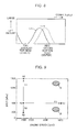
- FIG. 1 is a graph showing a relationship between an excess air ratio ⁇ and the NOx generation amount (combustion-generated, raw NOx amount).
- the value Y on the vertical axis indicates a NOx amount which can sufficiently meet the emission regulations if a NOx catalyst is provided
- the value X on the vertical axis indicates a NOx amount which can sufficiently meet the emission regulations without providing a NOx catalyst.
- the excess air ratio ⁇ which is a ratio of an actual air-fuel ratio to the stoichiometric air-fuel ratio (a value obtained by dividing an actual air-fuel ratio by the stoichiometric air-fuel ratio) is increased to 2.4 (equal to an actual air-fuel ratio of about 35) or more, the combustion-generated raw NOx amount becomes equal to or less than the reference value X, so that it becomes possible to sufficiently meet the emission regulations without providing a NOx catalyst.
- the NOx amount is less than the reference value Y although it becomes greater than the reference value X, so that it is possible to sufficiently meet the emission regulations as long as a NOx catalyst is provided.
- the problem concerning the NOx emission level can be cleared by setting the excess air ratio ⁇ , i.e., a ratio of an actual air-fuel ratio to the stoichiometric air-fuel ratio, to 2 or more, more preferably 2.4 or more.
- the excess air ratio ⁇ is set to 2.4 or more ( ⁇ ⁇ 2.4)
- a NOx catalyst can be omitted, which is more advantageous in terms of cost, than when the excess air ratio ⁇ is set in the range of 2 to less than 2.4.
- the compression self-ignition combustion in a gasoline engine is a phenomenon that fuel (gasoline) and oxygen (O 2 ) chemically react with each other on an autonomous basis, as shown in FIG. 2 .
- fuel gasoline
- oxygen oxygen
- FIG. 2 When a chemical reaction between fuel and oxygen, water and carbon dioxide are produced while generating heat due to an internal energy difference. Whether such a chemical reaction occurs is determined by a temperature and a pressure of an air-fuel mixture, and a high-temperature/high-pressure period (period where the air-fuel mixture is exposed to high temperatures and high pressures). More specifically, a molecular velocity becomes higher as the temperature becomes higher, and a molecular collision frequency becomes higher as the pressure (i.e., molecular density) becomes higher.
- FIG. 3 schematically shows a typical gasoline engine comprising a piston and a cylinder.
- MBT ignition timing Minimum Advance for Best Torque
- the MBT ignition timing (optimal ignition timing) varies depending on engine load, it is roughly in the range from a timing corresponding to a compression top dead center (compression TDC) (during high engine loads) to 3 degrees CA ATDC (during low engine loads).
- compression TDC means a top dead center between a compression stroke and a subsequent expansion stroke
- degrees CA ATDC means a crank angle after a top dead center.
- the in-cylinder temperature T and the in-cylinder pressure P just before the MBT ignition timing As a prerequisite to causing an air-fuel mixture to self-ignite at the MBT ignition timing, it is necessary to control the in-cylinder temperature T and the in-cylinder pressure P just before the MBT ignition timing, according to engine speed. Specifically, the high-temperature/high-pressure period of the air-fuel mixture becomes shorter as the engine speed becomes higher, and becomes longer as the engine speed becomes lower. Thus, it is necessary to raise the in-cylinder temperature and pressure T, P just before the MBT ignition timing, in a high engine speed range where the high-temperature/high-pressure period is relatively short, and to lower the in-cylinder temperature and pressure T, P just before the MBT ignition timing, in a low engine speed region where the high-temperature/high-pressure period is relatively long.
- the MBT ignition timing is limited to a vicinity of a compression TDC.
- an in-cylinder temperature and an in-cylinder pressure at a compression TDC will be used as respective representative examples of the in-cylinder temperature T and the in-cylinder pressure P just before the MBT ignition timing (i.e., just before the air-fuel mixture self-ignites), and will be referred to respectively as “compression end temperature Tx" and “compression end pressure Px”.
- FIG. 4 is a graph prepared by calculating a condition of the compression end temperature Tx and the compression end pressure Px (the in-cylinder temperature and the in-cylinder pressure at a compression TDC) for causing an air-fuel mixture to self-ignite at the MBT ignition timing (optimal ignition timing) when the engine speed is 1000 rpm, based on an elementary reaction calculation and a state equation.
- the excess air ratio ⁇ i.e., a ratio of an actual air-fuel ratio to the stoichiometric air-fuel ratio
- a compression ratio was set to 18.
- the excess air ratio ⁇ was set to 2.4, because the combustion- generated NOx amount (raw NOx amount) itself can be sufficiently reduced so as to meet the emission regulations even if a NOx catalyst is omitted (see the section (1-1)). Further, the compression ratio was set to 18, because it is necessary to raise a temperature and a pressure of the air-fuel mixture based on a compression ratio greater that that in a standard reciprocating gasoline engine, in order to cause the air-fuel mixture to self-ignite under the ultra-lean air-fuel ratio ( ⁇ 2.4), and the high-compression ratio is also advantageous in terms of engine thermal efficiency.
- the line L1 is formed by connecting respective values of the compression end temperature Tx and the compression end pressure Px required for self-ignition of the air-fuel mixture at the MBT ignition timing.
- Tx, Px are plotted on the line L1, a timing of the self-ignition is coincident with the MBT ignition timing.
- each of the lines M1, M2, M3 represents a value of the engine load based on an amount of fresh air to be introduced into a cylinder of the engine, wherein the line M1, the line M2 and the line M3 represent a full engine load, a 1/3 engine load and a no engine load, respectively.
- the fresh air amount (engine load) is proportional to the compression end pressure Px, and inversely proportional to the compression end temperature Tx. Therefore, the plurality of lines M1 to M3 each having a different slope can be defined for each value of the engine load.
- an IMEP at the full engine load (M1), an IMEP at the 1/3 engine load (M2) and an IMEP at the no engine load (M3) are 1300 kPa, 500 kPa and 200 kPa, respectively.
- the condition for causing the air-fuel mixture to self-ignite at the MBT ignition timing (line L1) is more largely shifted to a high-temperature/low-pressure side as the engine load becomes lower, and conversely more largely shifted to a low- temperature/high-pressure side as the engine load becomes higher.
- the molecular collision frequency becomes lower.
- the compression end temperature Tx it is necessary to raise the compression end temperature Tx to increase the molecular velocity.
- the engine load is high and thereby the fresh air amount is large, the molecular collision frequency becomes higher.
- the self-ignition timing becomes earlier than the MBT ignition timing. If the temperature-pressure condition are deviated to a lower temperature/lower pressure side (lower left side of the graph) than the line L1, the self-ignition timing becomes later than the MBT ignition timing. Thus, if the temperature-pressure condition is largely deviated to the higher temperature/higher pressure side or the lower temperature/lower pressure side with respect to the line L1, preignition or knocking will occur on the higher temperature/higher pressure side, or misfire will occur on the lower temperature/lower pressure side.
- FIG. 5 shows a result obtained by performing the same calculation as that for FIG. 4 while variously changing only the engine speed on the basis of the graph of FIG. 4 .
- the line L1 represents the temperature-pressure condition when the engine speed is 1000 rpm, as with the line L1 in FIG. 4
- the remaining lines L2, L3, L4, L5, L6 represent temperature-pressure conditions when the engine speed is 2000 rpm, 3000 rpm, 4000 rpm, 5000 rpm and 6000 rpm, respectively.
- each of the lines L2 to L6 representing the temperature-pressure conditions at the respective engine speeds 2000 rpm to 6000 rpm slopes downwardly and rightwardly, with a tendency similar to the line L1 at 1000 rpm.
- the lines L1 to L6 are located in order of L1, L2, -—, L6 in a rightward direction, which shows that it is necessary to raise the compression end temperature Tx along with an increase in the engine speed, so as to ensure the self-ignition. This is because the period where the air-fuel mixture is exposed to high temperatures and high pressures (high-temperature/high-pressure period) becomes shorter as the engine speed becomes higher, and thereby it is necessary to induce the chemical reaction within a shorter period of time.
- each of the lines L1 to L6 has the downward and rightward sloping, which shows that the temperature-pressure condition for causing the air-fuel mixture to self-ignite at the MBT ignition timing is more largely shifted to a high-temperature/low-pressure side as the engine load becomes lower, and more largely shifted to a low-temperature/high-pressure side as the engine load becomes higher, irrespective of engine speed values.
- compression initial temperature compression initial temperature
- the compression ratio is maintained constant, the compression end temperature Tx is not changed according to an increase/decrease in the engine load (i.e., increase/reduction in the fresh air amount), although only the compression end pressure Px is changed.
- the zone W indicated by the hatched lines in FIG. 5 denotes a range of the compression end temperature Tx and the compression end pressure Px to be obtained by compressing a certain amount of fresh air having a normal temperature (which corresponds to a compression initial temperature of 75oC) and an atmospheric pressure (0.1 MPa), at a compression ratio of 16 to 18.
- a normal temperature which corresponds to a compression initial temperature of 75oC
- an atmospheric pressure 0.1 MPa
- the inventors came up with an idea of creating substantially the same condition as the region S indicative of the condition for the adequate compression self-ignition combustion, by additionally performing supercharging and/or internal exhaust gas recirculation (internal EGR) while changing the engine compression ratio in a range equal to or less than 18.
- internal EGR internal exhaust gas recirculation
- a technique may be employed which is designed to retard an intake-valve closing timing under a condition that a geometric compression ratio of an engine is set to 18.
- a compression start timing is retarded, so that a substantial compression ratio (effective compression ratio) of the engine becomes less than 18.
- An operation of reducing the effective compression ratio leads to lowering of the compression end temperature Tx, so that it is effective particularly in a low engine speed/ high engine load range (upper left portion of the region S in FIG. 5 ).
- the intake-valve closing timing is retarded so as to reduce the effective compression ratio, the fresh air amount (amount of fresh air to be introduced into the cylinder) is reduced.
- the effective compression ratio is simply reduced, the compression end pressure Px is excessively lowered as compared with the temperature-pressure condition for the self-ignition in the low engine speed/high engine load range, which causes insufficiency in torque, or misfire. Therefore, in conjunction with a reduction in the effective compression ratio, supercharging is performed to compensate for a reduction of the fresh air amount.
- FIG. 6 is a schematic diagram showing an overall configuration of an engine according to one embodiment of the present invention made based on the above basic theory.
- the engine illustrated in FIG. 6 is a multi-cylinder gasoline engine including an engine body 1 which comprises a cylinder block 3 having a plurality of cylinders 2 (only one of them is illustrated in FIG. 6 ) arranged in a direction perpendicular to the drawing sheet, and a cylinder head 4 disposed on the cylinder block 3.
- fuel to be supplied to the engine body 1 may be any type consisting mainly of gasoline, wherein a content of the fuel may consist only of gasoline, or may contain gasoline and other component such as methanol (ethyl alcohol).
- a piston 5 is inserted in each of the cylinders 2 of the engine body 1 in a reciprocatingly slidable manner.
- the piston 5 is connected to a crankshaft 7 through a connecting rod 8 to allow the crankshaft 7 to be rotated about a central axis thereof according to a reciprocating movement of the piston 5.
- a combustion chamber 6 is defined just above the piston 5, and the cylinder head 4 is formed with an intake port 9 and an exhaust port 10 each opened to the combustion chamber 6, and provided with an intake valve 11 and an exhaust valve 12 for opening and closing respective ones of the ports 9, 10.
- Each of the intake valve 11 and the exhaust valve 12 is adapted to be openably/closably driven by a respective one of a pair of valve operating mechanisms 13 each including a camshaft (not shown) provided in the cylinder head 4, in conjunction with the rotation of the crankshaft 7.
- a VVL mechanism 14 and a VVT mechanism 15 are incorporated in each of the valve operating mechanisms 13 for the intake valve 11 and the exhaust valve 12.
- the VVL is an abbreviation for Variable Valve Lift
- the VVL mechanism 14 is adapted to variably set a lift amount (valve opening amount) of each of the intake and exhaust valves 11, 12.
- the VVT is an abbreviation for Variable Valve Timing
- the VVT mechanism 15 is adapted to variably set opening and closing timings (phase angles) of each of the intake and exhaust valves 11, 12.
- various types have already been put into practical use, and commonly known, and detailed description thereof will be omitted here.
- a type disclosed in JP 2007-85241A may be employed,
- a spark plug 16 is provided in the cylinder head 4 of the engine body 1 such a manner that it is exposed to the combustion chamber 6 of each of the cylinders 2 from thereabove.
- the spark plug 16 is electrically connected to an ignition circuit 17 provided on the cylinder head 4, and adapted to generate a spark discharge in response to a supply of electric power from the ignition circuit 17 thereto.
- the compression self-ignition combustion is performed throughout the entire engine operating region, and a spark-ignition combustion is basically not performed, as described later.
- the spark-ignition combustion is necessary to eliminate a risk of misfire which is likely to occur in the compression self-ignition combustion.
- the spark plug 16 is used at least in such a case.
- An injector 18 is provided in the cylinder head 4 in such a manner that it is exposed to the combustion chamber 6 laterally from an intake side of the combustion chamber 6.
- the injector 10 is adapted to inject fuel (consisting mainly of gasoline) therefrom into the combustion chamber 6 in an intake stroke, etc., of the engine, so as to mix the injected fuel with air to form an air-fuel mixture having a desired air-fuel ratio in the combustion chamber 6.
- a geometric compression ratio which is determined by a stroke volume (swept volume of the piston 5) and a volume of the combustion chamber at a timing when the piston 5 is is a TDC position, is set to 18.
- An intake passage 20 and an exhaust passage 21 are connected to respective ones of the intake port 9 and the exhaust port 10 of the engine body 1.
- the intake passage 20 is adapted to supply combustion air (fresh air) to the combustion chamber 6 therethrough
- the exhaust passage 21 is adapted to discharge burned gas (exhaust gas) produced in the combustion chamber 6, to outside the engine body 1 therethrough.
- the intake passage 20 is provided with a throttle valve 22.
- the lift amount and the opening and closing timings of each of the intake and exhaust valves 11, 12 are variably set by operations of the VVL mechanism 14 and the VVT mechanism 15, as described above.
- an amount of intake air to be charged into the combustion chamber 6 can be adjusted to control an engine power output, without selectively opening and closing the throttle valve 22. Therefore, the throttle valve 22 is operated to shut off the intake passage 20, for example, during emergency stop of the engine, and basically maintained at a fully-opened position, irrespective of engine operating state. Based on allowing the throttle valve 22 to be maintained at the fully-opened position, it becomes possible to achieve a reduction in pumping loss.
- Fresh air passing through the intake passage 20 is compressed by a supercharger 25 and then supplied to the combustion chamber 6.
- the supercharger 25 comprises a compressor 26 disposed inside the intake passage 20, a turbine 27 disposed inside the exhaust passage 21, a coupling shaft 28 coupling the compressor 26 and the turbine 27 together, and an electric motor 29 adapted to rotationally drive the coupling shaft 28.
- the compressor 26 is rotated by receiving exhaust gas energy, the compressor 26 is rotated at a high speed interlockingly with the turbine 27, so that fresh air passing through the intake passage 20 is compressed and forcedly supplied to the combustion chamber 6. Further, according to need, the electric motor 29 is driven to assist the rotation of the compressor 26.
- the compressor 26 is composed of a relatively-large impeller excellent in compression performance.
- the supercharger 25 adapted to compress intake air using the large-size compressor 26 can bring out high supercharging performance, particularly, in a high engine load range having large exhaust gas energy. Further, according to need, the rotation assist is performed by the electric motor 29, to allow intake air to be compressed with excellent response.
- the intake passage 20 has a water-cooled intercooler 30 provided downstream of the compressor 26 and adapted to cool fresh air having a temperature raised by the supercharging.
- the exhaust passage 21 is provided with a bypass passage 33 for allowing exhaust gas to bypass the turbine 27, and an electrically-operated wastegate valve 34 adapted to selectively open and close the bypass passage 33.
- the wastegate valve 34 is operable to selectively open and close the bypass passage 33 so as to switch between a first state in which exhaust gas flows through the turbine 27 to rotationally drive the turbine 27, and a second state in which exhaust gas bypasses the turbine 27 to stop the rotation of the turbine 27.
- the exhaust passage is also provided with a catalytic converter 32 for purifying exhaust gas.
- the catalytic converter 32 is provided with a three-way catalyst housed therein, and adapted to purify harmful components contained exhaust gas passing therethrough by an action of the three-way catalyst.
- the above engine further comprises an ECU (Engine Control Unit) 40 composed, for example, of a conventional CPU, a conventional memory and others, to serve as control means (controller) for comprehensively controlling an operation of the engine.
- ECU Engine Control Unit
- the ECU 40 is electrically connected to a plurality of sensors installed at respective positions of the engine. More specifically, the ECU 40 is electrically connected to each of an engine speed sensor 51 for detecting a rotation speed of the crankshaft 7, an airflow sensor 52 for detecting an amount of fresh air passing through the intake passage 20, an accelerator pedal angle sensor 53 for detecting a depression amount (depression angle) of an accelerator (not shown) adapted to be depressed by a driver.
- Each of the sensors 51 to 53A is operable to input a detection value into the ECU 40 in the form of an electric signal.
- the ECU 40 is electrically connected to each of the VVL mechanism 14, the VVT mechanism 15, the ignition circuit 17, the injector 18, the throttle valve 22, the electric motor 29, and the wastegate valve 34, and adapted to output a driving control signal to each of these components.
- the ECU 40 has valve control means 41, supercharging control means 42 and injector control means 43.
- the valve control means 41 is designed to drive the VVL mechanism 14 and the VVL mechanism 15 to variably set a lift characteristic (opening and closing timings and a lift amount) of each of the intake and exhaust values 11, 12. More specifically, based on changing the lift characteristic of each of the intake and exhaust values 11, 12, the valve control means 41 has a function of controlling an amount of burned gas remaining in the combustion chamber 6 (internal EGR amount), and a function of controlling an effective compression ratio of the engine.
- the valve control means 41 changes the lift characteristic of each of the intake and exhaust values 11, 12, for example, in a manner as shown in FIG. 7 .
- the lines Lex represent the lift characteristic of the exhaust value 12
- the lines Lin represent the lift characteristic of the intake value 11,
- the range NVO on the horizontal axis represents a negative overlap period where both of the intake and exhaust valves 11, 12 are closed during transition from an exhaust stroke to a subsequent intake stroke.
- the valve control means 41 is operable to drive the VVL mechanism 14 and the VVT mechanism 15 to change the lift characteristic of each of the intake and exhaust values 11, 12 so as to increase/reduce the negative overlap period NVO to adjust internal. EGR amount, (amount of burned gas remaining in the combustion chamber 6).
- the valve control means 41 changes the lift characteristic of the intake valve 11, for example, in a mode as shown in FIG. 8 .
- the intake valve 11 is normally closed at a timing adjacent to and on a retard side of an intake BDC (bottom dead center of an intake stroke) (a timing just after an intake BDC), as indicated by the solid waveform in FIG. 8 .
- the effective compression ratio is identical to the geometric compression ratio (in this embodiment, 18).
- valve control means 41 is operable to increase/reduce an amount of retard (retard amount) of the closing timing of the intake valve 11 so as to variably set the effective compression ratio of the engine.
- FIG. 8 illustrate one example in which the VVT mechanism 15 for the intake valve 11 is activated to retard an operation timing (opening and closing timings) of the intake valve 11 to a retard side as indicated by the broken line in FIG. 8 .
- the VVT mechanism 15 is activated in the above manner, not only the closing timing but also the opening timing of the intake valve 11 are changed, and thereby the negative overlap period NOV illustrated in FIG. 7 is simultaneously changed.
- both of the VVL mechanism 14 and the VVT mechanism 15 may be activated to control the lift amount and the opening and closing timings in such a manner that only the closing timing of the intake valve 11 is variably changed while maintaining the opening timing of the intake valve 1.1 constant.
- the supercharging control means 42 is designed to control, the supercharger 25 by driving the electric motor 29 for the supercharger 25 according to need, and openably/closably driving the wastegate valve 34, so as to obtain an adequate supercharging pressure.
- the injector control means 43 is designed to control an injection timing and an injection amount (injection period) of fuel to be injected from the injector 18 into the combustion chamber 6. More specifically, the injector control means 43 has a function of controlling an air-fuel ratio in the cylinder by calculating a target fuel injection amount for obtaining a given air-fuel ratio, based on information, such as an intake air amount (fresh air amount) input from the airflow sensor 52, and opening the injector 18 only for a time corresponding to the target fuel injection amount.
- the injector control means 43 is operable to control the fuel injection amount from the injector 18 to allow an excess air ratio ⁇ which is a ratio of an actual air-fuel ratio to the stoichiometric air-fuel ratio to be maintained at 2.4 throughout the entire engine operating region.
- ⁇ is a ratio of an actual air-fuel ratio to the stoichiometric air-fuel ratio to be maintained at 2.4 throughout the entire engine operating region.
- FIG. 9 is an engine operating zone map, wherein the horizontal axis represents the engine speed, and the vertical axis represents the engine load (IMEP).
- Each of the arrowed lines A1, A2 in FIG. 9 denotes that the engine operating state is changed along a direction of the engine load axis (engine load-axis direction), and
- FIG. 10 shows how each of the effective compression ratio ⁇ ', an initial temperature T0 on a compression stroke (compression initial temperature T0) and an initial pressure P0 on the compression stroke (compression initial pressure P0) is changed according to the change in engine load along the engine load-axis direction.
- compression initial temperature TO and “compression initial pressure P0” here are defined, respectively, as an in-cylinder temperature and an in-cylinder pressure at a timing when the intake valve 11 is closed.
- compression initial pressure P0 is defined as a partial pressure of fresh air in the cylinder (a value obtained by subtracting a partial pressure of burned gas from a total pressure in the cylinder) at a closing timing of the intake valve 11,
- the compression initial temperature T0 is maintained at a normal temperature (75°C).
- the closing timing of the intake valve 11 is retarded by the valve control means 41, to reduce the effective compression ratio e' from 18 to 15, and the supercharger 25 is driven by the supercharging control means 42, to set the compression initial pressure P0 to be greater than the non-supercharging pressure by a given value.
- the compression initial temperature T0 is maintained at the normal temperature, as mentioned above.
- the internal EGR control for forming the negative overlap period to cause high-temperature burned gas to remain in the combustion chamber 6) is not performed.
- the control scheme for reducing the effective compression ratio ⁇ ' and raising the compression initial pressure P0 i.e., supercharging fresh air
- a position of the representative point R0 is located slightly on a lower temperature/higher pressure side than the zone W which is a temperature-pressure range to be obtained when fresh air having the atmospheric pressure is compressed at a compression ratio of 16 to 18
- the effective compression ratio e' is reduced to 15 while raising the compression initial pressure P0 (fresh air amount) by the supercharging, so as to lower the compression end temperature Tx and raise the compression end pressure Px, as compared with the zone. W.
- the effective compression ratio ⁇ is gradually reduced while raising the compression initial pressure P0 by the supercharging (i.e., increasing the fresh air amount), along with an increase in the engine load. This corresponds to changing the temperature-pressure condition upwardly along the line L1 on the graph of FIG. 5 (see the arrowed line A1a).
- the internal EGR is performed to gradually increase an amount of burned gas remaining in the cylinder (combustion chamber 6) so as to gradually raise the compression initial temperature T0 in a range equal to or greater than the normal temperature.
- the supercharging using the supercharger 25 is stopped when the engine operating state is shifted slightly on a lower engine load side than the representative point R0, and the internal EGR is performed in the above manner to lower a partial pressure of fresh air in the cylinder, so that the compression initial pressure P0 is lowered down to less than the atmospheric pressure along with a decrease of the engine load.
- the effective compression ratio e' is gradually increased while lowering the compression initial pressure P0 by the internal EGR (i.e., reducing the fresh air amount), along with a decrease in the engine load. This corresponds to changing the temperature-pressure condition downwardly along the line L1 on the graph of FIG. 5 (see the arrowed line A2a),
- the compression self-ignition combustion can be adequately performed in the low engine load range.
- a control scheme to be executed when the engine operating state is changed from the representative point R0 to a higher engine speed side as indicated by the arrowed line A3 in FIG. 9 will be described.
- a control scheme for raising the compression initial temperature T0 along with an increase in the engine speed is performed, as shown in FIG. 11 .
- the internal EGR is performed to gradually increase the burned gas amount (amount of burned gas remaining in the cylinder) so as to gradually raise the compression initial temperature TO in a range equal to or greater than the normal temperature.
- the effective compression ratio ⁇ ' and the compression initial pressure P0 when the engine speed is in the range of 1000 to 2000 rpm, the effective compression ratio ⁇ ' is set to be less than 18 (15 to less than 18), and the compression initial pressure P0 is set to be grater than the atmospheric pressure, by the supercharging. Further, in the range of 2000 to 6000 rpm which is a higher engine speed side than the above engine speed range, the effective compression ratio ⁇ ' is maintained at 18 equal to the geometric compression ratio, and the supercharging is performed at a relatively low level to set the compression initial pressure P0 to be slightly grater than the atmospheric pressure.
- the compression initial temperature T0 is raised by the internal EGR. This corresponds to changing the temperature-pressure condition rightwardly along the line M2 on the graph of FIG. 5 (see the arrowed line A3a).
- the compression self-ignition combustion can be adequately performed in the high engine speed range.
- the internal EGR amount is increased to raise the compression initial temperature T0 under the condition that the effective compression ratio ⁇ ' is fixed to 18, so that a density of fresh air becomes lower along with a rise in the temperature due to the internal EGR, which is likely to cause reduction in engine power output.
- the supercharging is performed at a relatively low level to slightly raise the compression initial pressure P0, so as to avoid lowering of the fresh air density to adequately ensure the engine power output.
- FIG. 10 illustrates the control scheme to be performed when only the engine load is changed under a constant engine speed of 1000 rpm
- a control pattern depending on the engine load is the same at any engine speed other than 1000 rpm.
- the engine speed is set to a constant value, such as 2000 rpm, 3000 rpm, 4000 rpm, 5000 rpm or 6000 rpm
- a control scheme may be employed which is configured to, on a higher engine load side than a given engine load, reduce the effective compression ratio ⁇ ' while increasing the fresh air amount (i.e., raising the compression initial pressure P0) by the supercharging, and, on a lower engine load side than the given engine load, increasing the effective compression ratio ⁇ ' while reducing the fresh air amount (i.e., lowering the compression initial pressure P0) by the internal EGR, as with the control scheme illustrated in FIG. 10 .
- FIG. 11 illustrates the control scheme to be performed when only the engine speed is changed under a constant engine load (IMEP) of 500 kPa
- IMEP constant engine load
- a control pattern depending on the engine speed is the same at any engine load (IMEP) other than 500 kPa.
- the compression initial temperature T0 may be raised by the internal EGR while performing the supercharging according to need, along with an increase in the engine speed, as with the control scheme illustrated in FIG. 11 .
- the internal EGR is performed to raise the compression initial temperature T0 so as to raise the compression end temperature Tx.
- the internal EGR is performed to obtain a larger internal EGR amount than those for the operating points R2, R2, so as to further raise the compression end temperature Tx. This makes it possible to perform the adequate the compression self-ignition combustion in the high engine speed/low engine load range.
- the zone V representing a high engine speed/high engine load range corresponds to an upper right portion of the region S as cross-referred with FIG. 5 .
- the effective compression ratio ⁇ ' may be set to a larger value than that for the operating point R1 Specifically, at the operating point R1, in order to create the condition that the compression end temperature Tx is relatively low and the compression end pressure Px is relatively high, the effective compression ratio ⁇ ' is reduced down to 10.5 while raising the compression initial pressure P0 by the supercharging. Differently, in the high engine speed/ high engine load range (zone V in FIG. 9 ), considering the need for more largely raising the compression end temperature Tx as compared with the operating point R1, the effective compression ratio ⁇ ' may be set to be greater than 10.5 so as to provide a higher in-cylinder temperature.
- the excess air ratio ⁇ i.e., a ratio of an actual air-fuel ratio to the stoichiometric air-fuel ratio
- the compression initial temperature T0 is raised by increasing the internal EGR amount (amount of burned gas remaining in the cylinder) with respect to the lower engine speed side.
- the internal EGR amount is increased as the engine speed becomes higher, to increase the compression initial temperature T0, so that primarily the (compression end temperature Tx can be raised, as indicated by the arrowed line A3a in FIG. 5 , so as to increase a collision velocity between fuel and oxygen molecules to facilitate a chemical reaction therebetween.
- the compression initial, pressure P0 is raised by the supercharging. This provides an advantage of being able to compensate for lowering of fresh air density due to the temperature rise, based on supercharged fresh air, so as to adequately ensure the engine power output, irrespective of engine speed values.
- This control scheme has an advantage of being able to allow the compression self-ignition combustion under a lean air-fuel ratio to be performed in a wider engine load range so as to more effectively enhance the engine thermal efficiency.
- the compression end temperature Tx can be lowered while raising the compression end pressure Px, as indicated by the arrowed line Ala in FIG. 5 , by increasing the fresh air amount based on the supercharging and reducing the effective compression ratio ⁇ ', according to an increase in the engine load, so that it becomes possible to sufficiently ensure the engine power output based on a large amount of supercharged fresh air, while reducing the collision velocity between fuel and oxygen molecules to suppress the chemical reaction therebetween so as to effectively prevent abnormal combustion, such as knocking or preignition.
- the compression end temperature Tx can be raised while lowering the compression end pressure Px, as indicated by the arrowed line A2a in FIG. 5 , by reducing the fresh air amount based on the internal EGR and increasing the effective compression ratio ⁇ ', so that it becomes possible to increase a molecular velocity to facilitate the chemical reaction so as to reliably cause an air-fuel mixture to self-ignite, even in a situation where the fresh air amount is small and thereby a frequency of the collision between fuel and the oxygen molecules is low.
- the compression self-ignition combustion under a lean air-fuel ratio can be adequately performed in a wider range along the engine load-axis direction to effectively enhance the engine thermal efficiency.
- the internal EGR for causing high-temperature burned gas to remain in the combustion chamber 6 is performed to reduce the fresh air amount on the lower engine load side than the given engine load, so that it becomes possible to not only reduce the fresh air amount but also raise the compression initial temperature T0, by internal EGR.
- This provides an advantage of being able to effectively create a condition of the compression end temperature Tx and the compression end pressure Px suitable for a low engine load so as to allow the compression self-ignition combustion under a lean air-fuel ratio to be adequately performed on the lower engine load side.
- respective parameters of the effective compression ratio e', the compression initial temperature T0 and the compression initial pressure P0 can be adequately controlled by taking advantage of supercharging, internal EGR, etc., to create the condition of the compression end temperature Tx and the compression end pressure Px as shown in FIG. 5 so as to allow the adequate compression self-ignition combustion (combustion mode where an air-fuel mixture self-ignites at the MBT ignition timing) to be performed throughout the entire engine operating region.
- the compression end temperature Tx just before ignition is raised by increasing a burned-gas remaining amount based on the internal EGR (internal EGR amount.) to raise the compression initial temperature T0 in the cylinder, for example, as shown in FIG. 11 .
- the technique for rising the compression end temperature Tx is not limited to the type based on the internal EGR.
- the compression end temperature Tx may be raised by activating the spark plug in a compression stroke to secondarily ignite a part of an air-fuel mixture. Based on raising the compression end temperature Tx by means of the secondary ignition in this manner, the remaining air-fuel mixture is allowed to self-ignite around the compression TDC (MBT). In this case, only the compression end temperature Tx is raised without raising the compression initial temperature T0.
- MBT compression TDC
- the combustion mode may be switched to the spark-ignition (SI) combustion mode where an air-fuel mixture is forcedly ignited by a spark discharge from the spark plug 16, wherein the compression self-ignition combustion is performed only in a partial engine load range.
- SI spark-ignition
- the excess air ratio ⁇ i.e., a ratio of an actual air-fuel ratio to the stoichiometric air-fuel ratio, is set to 2.4 throughout the entire engine operating region without exception to sufficiently reduce an amount of NOx to be produced from combustion (raw NOx amount) itself so as to sufficiently meet emission regulations even if a NOx catalyst is omitted.
- the excess air ratio ⁇ may be set to be less than 2.4 at lest in a part of the engine operating region.
- the excess air ratio ⁇ should be set to 2 or more. As described based on FIG. 1 , as long as the excess air ratio ⁇ ⁇ 2, NOx emissions can be reduced to a sufficient level by purifying the produced NOx through the NOx catalyst.
- the geometric compression ratio of the engine is set to 18.
- it may be set to any suitable value other than 18.
- the geometric compression ratio in view of the fast that the zone W representing a temperature-pressure range to be obtained when fresh air having the normal temperature and the atmospheric pressure is compressed at a compression ratio of 16 to 18, overlaps the region S representing the temperature-pressure condition required for the adequate compression self-ignition combustion, it is believed that, as long as the geometric compression ratio is set to at least 16 or more, the adequate compression self-ignition combustion can be performed in each engine operating zone as with the above embodiment, by appropriately changing the effective compression ratio ⁇ ' under a condition that the compression ratio 16 is defined as a maximum value of a control range. For this reason, the geometric compression ratio may be set to at least 16 or more.
- the negative overlap period NVO ( FIG. 7 ) where both of the intake and exhaust valves are closed during a transition from an exhaust stroke to a subsequent intake stroke, and the internal EGR for causing high-temperature burned gas to remain in the combustion chamber 6 is performed by means of the negative overlap period NVO.
- a technique for performing the internal EGR is not limited to the type utilizing the negative overlap period NVO.
- a technique may be employed which is designed to open one of the exhaust valves during an intake stroke to allow burned gas to return from an exhaust passage to a combustion chamber 6 on the intake stroke so as to cause the burned gas to remain in the combustion chamber 6.
- a method for controlling an engine comprises a step of allowing a compression self-ignition combustion under an air-fuel ratio leaner than a stoichiometric air-fuel ratio to be performed at least in a partial-load range of the engine, wherein, under a condition that an engine speed varies at a same load in an engine operating region of the compression self-ignition combustion, a compression end temperature, which is an in-cylinder temperature just before an air-fuel mixture self-ignites, is controlled to be raised higher in a higher engine speed side than in a lower engine speed side.
- an apparatus for controlling an engine comprises a controller adapted to control respective sections of the engine to allow a compression self-ignition combustion under an air-fuel ratio leaner than a stoichiometric air-fuel ratio to be performed at least in a partial-load range of the engine, wherein the controller is operable, under a condition that an engine speed varies at a same load in an engine operating region of the compression self-ignition combustion, to control a compression end temperature, which is an in-cylinder temperature just before an air-fuel mixture self-ignites, in such a manner that it is raised higher in a higher engine speed side than in a lower engine speed side.
- the compression end temperature is raised higher in the higher engine speed side than in the lower engine speed side, so that it becomes possible to increase a collision velocity between fuel and oxygen molecules as the engine speed becomes higher and thereby the high-temperature/high-pressure period in the cylinder becomes shorter, to facilitate a chemical reaction therebetween so as to reliably cause an air-fuel mixture to self-ignition.
- the control for raising compression end temperature includes a control for raising a compression initial temperature which is an in-cylinder temperature at a start timing of a compression stroke, wherein, the compression initial temperature is controlled to be raised higher in the higher engine speed side than in the lower engine speed side.
- the control for raising the compression end temperature includes a control for raising a compression initial temperature which is an in-cylinder temperature at a start timing of a compression stroke, wherein the controller is operable to control the compression initial temperature in such a manner that it is raised higher in the higher engine speed side than in the lower engine speed side.
- the compression end temperature is raised by raising the compression initial temperature, so as to allow the compression self-ignition combustion to be adequately performed in the high engine speed side.
- the control for raising the compression initial temperature includes a control for performing internal EGR for causing burned gas to remain in a cylinder, wherein, an internal EGR amount is controlled to be increased larger in the higher engine speed side than in the lower engine speed side.
- the control for raising the compression initial temperature includes a control for performing internal EGR for causing burned gas to remain in a cylinder, wherein the controller is operable to control an internal EGR amount in such a manner that it is increased larger in the higher engine speed side than in the lower engine speed side.
- the compression initial temperature can be adequately raised to a high value by allowing high-temperature burned gas to remain in the cylinder.
- the internal EGR amount is increased as the load becomes lower.
- the controller is operable, when the internal EGR is performed at a same engine speed, to increase the internal EGR amount as the load becomes lower.
- the above method comprises a step of raising a compression initial pressure which is an in-cylinder pressure at a start timing of a compression stroke, according to a rise in the compression initial temperature, by means of supercharging.
- the engine is equipped with a supercharger operable to supercharge fresh air, wherein the controller is operable, to activate the supercharger to raise a compression initial pressure which is an in-cylinder pressure at a start timing of a compression stroke, according to a rise in the compression initial temperature,
- an engine power output can be adequately ensured irrespective of engine speed values by compensating for lowering of fresh air density due to the rise in the compression initial temperature, based on the supercharging.
- a geometric compression ratio of the engine is 16 or more.
- a geometric compression ratio of the engine is set to 16 or more, so that an air-fuel mixture can be sufficiently increased in temperature/pressure so as to reliably cause the air-fuel mixture to self-ignite.
- a high compression ratio is also advantageous in terms of the engine thermal efficiency.
- an excess air ratio ⁇ which is a ratio of an actual air-fuel ratio to the stoichiometric air-fuel ratio, is set to 2 or more.
- the controller is operable, throughout the engine operating region subject to the compression self-ignition combustion, to set an excess air ratio ⁇ which is a ratio of an actual air-fuel ratio to the stoichiometric air-fuel ratio, to 2 or more.
- the compression self-ignition combustion is performed under a significantly lean air-fuel ratio corresponding to an excess air ratio ⁇ of 2 or more. This has an advantage of being able to effectively reduce an amount of NOx to be produced from combustion so as to sufficiently meet emission regulations.
Landscapes
- Engineering & Computer Science (AREA)
- Chemical & Material Sciences (AREA)
- Combustion & Propulsion (AREA)
- Mechanical Engineering (AREA)
- General Engineering & Computer Science (AREA)
- Electrical Control Of Air Or Fuel Supplied To Internal-Combustion Engine (AREA)
- Combustion Methods Of Internal-Combustion Engines (AREA)
- Output Control And Ontrol Of Special Type Engine (AREA)
- Combined Controls Of Internal Combustion Engines (AREA)
Applications Claiming Priority (1)
| Application Number | Priority Date | Filing Date | Title |
|---|---|---|---|
| JP2010014907A JP5644123B2 (ja) | 2010-01-27 | 2010-01-27 | エンジンの制御方法および制御装置 |
Publications (3)
| Publication Number | Publication Date |
|---|---|
| EP2354508A2 true EP2354508A2 (de) | 2011-08-10 |
| EP2354508A3 EP2354508A3 (de) | 2014-09-24 |
| EP2354508B1 EP2354508B1 (de) | 2018-04-11 |
Family
ID=43855933
Family Applications (1)
| Application Number | Title | Priority Date | Filing Date |
|---|---|---|---|
| EP11151985.6A Not-in-force EP2354508B1 (de) | 2010-01-27 | 2011-01-25 | Verfahren und Vorrichtung zur Motorsteuerung |
Country Status (4)
| Country | Link |
|---|---|
| US (1) | US8783227B2 (de) |
| EP (1) | EP2354508B1 (de) |
| JP (1) | JP5644123B2 (de) |
| CN (1) | CN102135038B (de) |
Cited By (1)
| Publication number | Priority date | Publication date | Assignee | Title |
|---|---|---|---|---|
| EP2357345A3 (de) * | 2010-01-27 | 2018-07-11 | Mazda Motor Corporation | Verfahren und Vorrichtung zur Steuerung eines Kompressormotors während Verdichtungszündung |
Families Citing this family (21)
| Publication number | Priority date | Publication date | Assignee | Title |
|---|---|---|---|---|
| JP5644123B2 (ja) * | 2010-01-27 | 2014-12-24 | マツダ株式会社 | エンジンの制御方法および制御装置 |
| JP5794049B2 (ja) * | 2011-09-06 | 2015-10-14 | マツダ株式会社 | 火花点火式4サイクルリーンバーンエンジン |
| JP5716864B2 (ja) * | 2012-03-09 | 2015-05-13 | 日産自動車株式会社 | 過給機付内燃機関の制御装置および制御方法 |
| US9062577B2 (en) * | 2012-05-14 | 2015-06-23 | Southwest Research Institute | Diesel engine operation for fast transient response and low emissions |
| JP6249667B2 (ja) * | 2013-08-07 | 2017-12-20 | 本田技研工業株式会社 | 内燃機関の制御装置 |
| JP6249668B2 (ja) * | 2013-08-07 | 2017-12-20 | 本田技研工業株式会社 | 内燃機関の制御装置 |
| CN104948325B (zh) * | 2014-03-26 | 2019-08-27 | 周向进 | 一种汽油机及其测试汽油辛烷值的方法 |
| DE102015013794A1 (de) * | 2015-10-22 | 2017-04-27 | Man Truck & Bus Ag | Verfahren zum Betreiben einer Brennkraftmaschine, insbesondere eines Dieselmotors |
| WO2018096587A1 (ja) * | 2016-11-22 | 2018-05-31 | マツダ株式会社 | 圧縮自己着火式エンジンの制御装置 |
| JP6558408B2 (ja) * | 2016-11-22 | 2019-08-14 | マツダ株式会社 | 圧縮自己着火式エンジンの制御装置 |
| WO2018096585A1 (ja) * | 2016-11-22 | 2018-05-31 | マツダ株式会社 | 圧縮自己着火式エンジンの制御装置 |
| WO2018096586A1 (ja) * | 2016-11-22 | 2018-05-31 | マツダ株式会社 | 圧縮自己着火式エンジンの制御装置 |
| CN108779730B (zh) * | 2016-11-22 | 2022-01-11 | 马自达汽车株式会社 | 压缩自燃式发动机的控制装置 |
| WO2018096652A1 (ja) * | 2016-11-25 | 2018-05-31 | マツダ株式会社 | 圧縮自己着火式エンジンの制御装置 |
| JP6555321B2 (ja) * | 2017-11-10 | 2019-08-07 | マツダ株式会社 | 圧縮着火式エンジンの制御装置 |
| JP7115028B2 (ja) * | 2018-05-22 | 2022-08-09 | マツダ株式会社 | 圧縮着火式エンジンの制御装置 |
| JP7225593B2 (ja) * | 2018-07-26 | 2023-02-21 | マツダ株式会社 | 圧縮着火式エンジンの制御装置 |
| CA3140048A1 (en) | 2019-05-15 | 2020-11-19 | Clearflame Engines, Inc. | Cold-start for high-octane fuels in a diesel engine architecture |
| JP2023516273A (ja) | 2020-02-26 | 2023-04-19 | クリアフレーム エンジンズ,インコーポレイテッド | 燃料に依存しない圧縮着火エンジン |
| BR112023000330A2 (pt) | 2020-07-09 | 2023-03-28 | Clearflame Engines Inc | Sistemas e métodos de desativação de cilindro em motores com controle de mistura em alta temperatura |
| CN115234387B (zh) * | 2022-07-14 | 2023-10-10 | 北京理工大学 | 一种对置活塞发动机全工况功率和热效率双元调控方法 |
Citations (3)
| Publication number | Priority date | Publication date | Assignee | Title |
|---|---|---|---|---|
| JP2007085241A (ja) | 2005-09-21 | 2007-04-05 | Mazda Motor Corp | 火花点火式エンジン |
| JP2007292060A (ja) | 2006-03-31 | 2007-11-08 | Mazda Motor Corp | 火花点火式ガソリンエンジン |
| JP2010014907A (ja) | 2008-07-02 | 2010-01-21 | Seiko Epson Corp | 発光装置 |
Family Cites Families (15)
| Publication number | Priority date | Publication date | Assignee | Title |
|---|---|---|---|---|
| JP2000213384A (ja) * | 1999-01-26 | 2000-08-02 | Osaka Gas Co Ltd | 圧縮自着火エンジン |
| JP2001289092A (ja) * | 2000-04-03 | 2001-10-19 | Nissan Motor Co Ltd | 圧縮自己着火式内燃機関 |
| EP1310649B1 (de) | 2000-08-17 | 2016-11-23 | Hitachi, Ltd. | Dieselbrennkraftmaschine |
| JP3945152B2 (ja) * | 2000-11-21 | 2007-07-18 | 日産自動車株式会社 | 内燃機関の燃焼制御装置 |
| JP3743283B2 (ja) * | 2000-12-08 | 2006-02-08 | 日産自動車株式会社 | 過給機付き圧縮自己着火式内燃機関 |
| JP2004036595A (ja) * | 2002-07-08 | 2004-02-05 | Honda Motor Co Ltd | 圧縮着火式内燃機関の制御装置 |
| AT500692B1 (de) * | 2003-01-16 | 2008-01-15 | Ge Jenbacher Gmbh & Co Ohg | Verbrennunsmotor mit mindestens einem zylinder |
| JP4036165B2 (ja) * | 2003-08-29 | 2008-01-23 | トヨタ自動車株式会社 | 自着火エンジン |
| JP2005120969A (ja) * | 2003-10-20 | 2005-05-12 | Toyota Motor Corp | 筒内噴射式エンジンの制御装置 |
| JP4645456B2 (ja) * | 2006-01-23 | 2011-03-09 | 株式会社豊田自動織機 | 予混合圧縮自着火燃焼機関の制御装置 |
| JP4232818B2 (ja) * | 2006-11-29 | 2009-03-04 | トヨタ自動車株式会社 | 内燃機関の点火制御システム |
| JP2009191659A (ja) * | 2008-02-12 | 2009-08-27 | Toyota Motor Corp | 内燃機関の制御装置 |
| JP5644123B2 (ja) * | 2010-01-27 | 2014-12-24 | マツダ株式会社 | エンジンの制御方法および制御装置 |
| JP5540729B2 (ja) * | 2010-01-27 | 2014-07-02 | マツダ株式会社 | 過給機付エンジンの制御方法および制御装置 |
| JP4924751B1 (ja) * | 2010-11-09 | 2012-04-25 | マツダ株式会社 | 火花点火式直噴エンジンの制御方法及びその制御装置 |
-
2010
- 2010-01-27 JP JP2010014907A patent/JP5644123B2/ja not_active Expired - Fee Related
-
2011
- 2011-01-24 US US13/012,406 patent/US8783227B2/en not_active Expired - Fee Related
- 2011-01-25 EP EP11151985.6A patent/EP2354508B1/de not_active Not-in-force
- 2011-01-26 CN CN201110037517.4A patent/CN102135038B/zh not_active Expired - Fee Related
Patent Citations (3)
| Publication number | Priority date | Publication date | Assignee | Title |
|---|---|---|---|---|
| JP2007085241A (ja) | 2005-09-21 | 2007-04-05 | Mazda Motor Corp | 火花点火式エンジン |
| JP2007292060A (ja) | 2006-03-31 | 2007-11-08 | Mazda Motor Corp | 火花点火式ガソリンエンジン |
| JP2010014907A (ja) | 2008-07-02 | 2010-01-21 | Seiko Epson Corp | 発光装置 |
Cited By (1)
| Publication number | Priority date | Publication date | Assignee | Title |
|---|---|---|---|---|
| EP2357345A3 (de) * | 2010-01-27 | 2018-07-11 | Mazda Motor Corporation | Verfahren und Vorrichtung zur Steuerung eines Kompressormotors während Verdichtungszündung |
Also Published As
| Publication number | Publication date |
|---|---|
| JP2011153554A (ja) | 2011-08-11 |
| EP2354508A3 (de) | 2014-09-24 |
| US20110180038A1 (en) | 2011-07-28 |
| US8783227B2 (en) | 2014-07-22 |
| CN102135038B (zh) | 2015-09-09 |
| EP2354508B1 (de) | 2018-04-11 |
| JP5644123B2 (ja) | 2014-12-24 |
| CN102135038A (zh) | 2011-07-27 |
Similar Documents
| Publication | Publication Date | Title |
|---|---|---|
| EP2354508B1 (de) | Verfahren und Vorrichtung zur Motorsteuerung | |
| US8459021B2 (en) | Method and apparatus for controlling supercharged engine | |
| CN102884300B (zh) | 火花点火引擎的控制方法以及火花点火引擎 | |
| EP2553248B1 (de) | Steuersystem für einen benzinmotor | |
| JP5915472B2 (ja) | 火花点火式直噴エンジン | |
| JP5998751B2 (ja) | 火花点火式直噴エンジン | |
| JP4748255B2 (ja) | エンジンの制御方法および制御装置 | |
| US20100077990A1 (en) | Control of spark ignited internal combustion engine | |
| JP5540730B2 (ja) | 火花点火式エンジンの制御装置 | |
| JP2014185623A (ja) | 火花点火式エンジンの制御装置 | |
| WO2018096590A1 (ja) | 圧縮自己着火式エンジンの制御装置 | |
| WO2018096587A1 (ja) | 圧縮自己着火式エンジンの制御装置 | |
| WO2018096947A1 (ja) | 圧縮自己着火式エンジンの制御装置 | |
| JP5428473B2 (ja) | 内燃機関を制御する方法及び装置 | |
| JP2010144558A (ja) | エンジンの制御方法および制御装置 | |
| JP2019039393A (ja) | 過給システム付きエンジン | |
| JP3791256B2 (ja) | 圧縮自己着火ガソリン内燃機関 | |
| JP2011214478A (ja) | エンジンの制御装置 | |
| JP6221901B2 (ja) | エンジンの制御装置 | |
| JP7131171B2 (ja) | 圧縮着火式エンジンの制御装置 | |
| JP2011058372A (ja) | エンジンの制御方法およびその制御装置 | |
| JP2004239065A (ja) | レシプロエンジンおよびその制御方法 | |
| JP4470724B2 (ja) | 副室式内燃機関 | |
| JP5910423B2 (ja) | 火花点火式エンジン | |
| JP2019052607A (ja) | オゾン添加システム |
Legal Events
| Date | Code | Title | Description |
|---|---|---|---|
| PUAI | Public reference made under article 153(3) epc to a published international application that has entered the european phase |
Free format text: ORIGINAL CODE: 0009012 |
|
| AK | Designated contracting states |
Kind code of ref document: A2 Designated state(s): AL AT BE BG CH CY CZ DE DK EE ES FI FR GB GR HR HU IE IS IT LI LT LU LV MC MK MT NL NO PL PT RO RS SE SI SK SM TR |
|
| AX | Request for extension of the european patent |
Extension state: BA ME |
|
| PUAL | Search report despatched |
Free format text: ORIGINAL CODE: 0009013 |
|
| AK | Designated contracting states |
Kind code of ref document: A3 Designated state(s): AL AT BE BG CH CY CZ DE DK EE ES FI FR GB GR HR HU IE IS IT LI LT LU LV MC MK MT NL NO PL PT RO RS SE SI SK SM TR |
|
| AX | Request for extension of the european patent |
Extension state: BA ME |
|
| RIC1 | Information provided on ipc code assigned before grant |
Ipc: F02D 35/02 20060101ALN20140819BHEP Ipc: F02D 41/00 20060101ALI20140819BHEP Ipc: F02D 41/30 20060101AFI20140819BHEP |
|
| 17P | Request for examination filed |
Effective date: 20150312 |
|
| RBV | Designated contracting states (corrected) |
Designated state(s): AL AT BE BG CH CY CZ DE DK EE ES FI FR GB GR HR HU IE IS IT LI LT LU LV MC MK MT NL NO PL PT RO RS SE SI SK SM TR |
|
| 17Q | First examination report despatched |
Effective date: 20150907 |
|
| 17Q | First examination report despatched |
Effective date: 20150918 |
|
| GRAP | Despatch of communication of intention to grant a patent |
Free format text: ORIGINAL CODE: EPIDOSNIGR1 |
|
| STAA | Information on the status of an ep patent application or granted ep patent |
Free format text: STATUS: GRANT OF PATENT IS INTENDED |
|
| INTG | Intention to grant announced |
Effective date: 20171204 |
|
| GRAS | Grant fee paid |
Free format text: ORIGINAL CODE: EPIDOSNIGR3 |
|
| GRAA | (expected) grant |
Free format text: ORIGINAL CODE: 0009210 |
|
| STAA | Information on the status of an ep patent application or granted ep patent |
Free format text: STATUS: THE PATENT HAS BEEN GRANTED |
|
| AK | Designated contracting states |
Kind code of ref document: B1 Designated state(s): AL AT BE BG CH CY CZ DE DK EE ES FI FR GB GR HR HU IE IS IT LI LT LU LV MC MK MT NL NO PL PT RO RS SE SI SK SM TR |
|
| REG | Reference to a national code |
Ref country code: GB Ref legal event code: FG4D |
|
| REG | Reference to a national code |
Ref country code: CH Ref legal event code: EP |
|
| REG | Reference to a national code |
Ref country code: AT Ref legal event code: REF Ref document number: 988287 Country of ref document: AT Kind code of ref document: T Effective date: 20180415 |
|
| REG | Reference to a national code |
Ref country code: IE Ref legal event code: FG4D |
|
| REG | Reference to a national code |
Ref country code: DE Ref legal event code: R096 Ref document number: 602011047308 Country of ref document: DE |
|
| REG | Reference to a national code |
Ref country code: NL Ref legal event code: MP Effective date: 20180411 |
|
| REG | Reference to a national code |
Ref country code: LT Ref legal event code: MG4D |
|
| PG25 | Lapsed in a contracting state [announced via postgrant information from national office to epo] |
Ref country code: NL Free format text: LAPSE BECAUSE OF FAILURE TO SUBMIT A TRANSLATION OF THE DESCRIPTION OR TO PAY THE FEE WITHIN THE PRESCRIBED TIME-LIMIT Effective date: 20180411 |
|
| REG | Reference to a national code |
Ref country code: DE Ref legal event code: R084 Ref document number: 602011047308 Country of ref document: DE |
|
| PG25 | Lapsed in a contracting state [announced via postgrant information from national office to epo] |
Ref country code: AL Free format text: LAPSE BECAUSE OF FAILURE TO SUBMIT A TRANSLATION OF THE DESCRIPTION OR TO PAY THE FEE WITHIN THE PRESCRIBED TIME-LIMIT Effective date: 20180411 Ref country code: BG Free format text: LAPSE BECAUSE OF FAILURE TO SUBMIT A TRANSLATION OF THE DESCRIPTION OR TO PAY THE FEE WITHIN THE PRESCRIBED TIME-LIMIT Effective date: 20180711 Ref country code: FI Free format text: LAPSE BECAUSE OF FAILURE TO SUBMIT A TRANSLATION OF THE DESCRIPTION OR TO PAY THE FEE WITHIN THE PRESCRIBED TIME-LIMIT Effective date: 20180411 Ref country code: LT Free format text: LAPSE BECAUSE OF FAILURE TO SUBMIT A TRANSLATION OF THE DESCRIPTION OR TO PAY THE FEE WITHIN THE PRESCRIBED TIME-LIMIT Effective date: 20180411 Ref country code: NO Free format text: LAPSE BECAUSE OF FAILURE TO SUBMIT A TRANSLATION OF THE DESCRIPTION OR TO PAY THE FEE WITHIN THE PRESCRIBED TIME-LIMIT Effective date: 20180711 Ref country code: SE Free format text: LAPSE BECAUSE OF FAILURE TO SUBMIT A TRANSLATION OF THE DESCRIPTION OR TO PAY THE FEE WITHIN THE PRESCRIBED TIME-LIMIT Effective date: 20180411 Ref country code: ES Free format text: LAPSE BECAUSE OF FAILURE TO SUBMIT A TRANSLATION OF THE DESCRIPTION OR TO PAY THE FEE WITHIN THE PRESCRIBED TIME-LIMIT Effective date: 20180411 Ref country code: PL Free format text: LAPSE BECAUSE OF FAILURE TO SUBMIT A TRANSLATION OF THE DESCRIPTION OR TO PAY THE FEE WITHIN THE PRESCRIBED TIME-LIMIT Effective date: 20180411 |
|
| PG25 | Lapsed in a contracting state [announced via postgrant information from national office to epo] |
Ref country code: RS Free format text: LAPSE BECAUSE OF FAILURE TO SUBMIT A TRANSLATION OF THE DESCRIPTION OR TO PAY THE FEE WITHIN THE PRESCRIBED TIME-LIMIT Effective date: 20180411 Ref country code: LV Free format text: LAPSE BECAUSE OF FAILURE TO SUBMIT A TRANSLATION OF THE DESCRIPTION OR TO PAY THE FEE WITHIN THE PRESCRIBED TIME-LIMIT Effective date: 20180411 Ref country code: HR Free format text: LAPSE BECAUSE OF FAILURE TO SUBMIT A TRANSLATION OF THE DESCRIPTION OR TO PAY THE FEE WITHIN THE PRESCRIBED TIME-LIMIT Effective date: 20180411 Ref country code: GR Free format text: LAPSE BECAUSE OF FAILURE TO SUBMIT A TRANSLATION OF THE DESCRIPTION OR TO PAY THE FEE WITHIN THE PRESCRIBED TIME-LIMIT Effective date: 20180712 |
|
| REG | Reference to a national code |
Ref country code: AT Ref legal event code: MK05 Ref document number: 988287 Country of ref document: AT Kind code of ref document: T Effective date: 20180411 |
|
| PG25 | Lapsed in a contracting state [announced via postgrant information from national office to epo] |
Ref country code: PT Free format text: LAPSE BECAUSE OF FAILURE TO SUBMIT A TRANSLATION OF THE DESCRIPTION OR TO PAY THE FEE WITHIN THE PRESCRIBED TIME-LIMIT Effective date: 20180813 |
|
| REG | Reference to a national code |
Ref country code: DE Ref legal event code: R097 Ref document number: 602011047308 Country of ref document: DE |
|
| PG25 | Lapsed in a contracting state [announced via postgrant information from national office to epo] |
Ref country code: RO Free format text: LAPSE BECAUSE OF FAILURE TO SUBMIT A TRANSLATION OF THE DESCRIPTION OR TO PAY THE FEE WITHIN THE PRESCRIBED TIME-LIMIT Effective date: 20180411 Ref country code: SK Free format text: LAPSE BECAUSE OF FAILURE TO SUBMIT A TRANSLATION OF THE DESCRIPTION OR TO PAY THE FEE WITHIN THE PRESCRIBED TIME-LIMIT Effective date: 20180411 Ref country code: CZ Free format text: LAPSE BECAUSE OF FAILURE TO SUBMIT A TRANSLATION OF THE DESCRIPTION OR TO PAY THE FEE WITHIN THE PRESCRIBED TIME-LIMIT Effective date: 20180411 Ref country code: AT Free format text: LAPSE BECAUSE OF FAILURE TO SUBMIT A TRANSLATION OF THE DESCRIPTION OR TO PAY THE FEE WITHIN THE PRESCRIBED TIME-LIMIT Effective date: 20180411 Ref country code: EE Free format text: LAPSE BECAUSE OF FAILURE TO SUBMIT A TRANSLATION OF THE DESCRIPTION OR TO PAY THE FEE WITHIN THE PRESCRIBED TIME-LIMIT Effective date: 20180411 Ref country code: DK Free format text: LAPSE BECAUSE OF FAILURE TO SUBMIT A TRANSLATION OF THE DESCRIPTION OR TO PAY THE FEE WITHIN THE PRESCRIBED TIME-LIMIT Effective date: 20180411 |
|
| PLBE | No opposition filed within time limit |
Free format text: ORIGINAL CODE: 0009261 |
|
| STAA | Information on the status of an ep patent application or granted ep patent |
Free format text: STATUS: NO OPPOSITION FILED WITHIN TIME LIMIT |
|
| PG25 | Lapsed in a contracting state [announced via postgrant information from national office to epo] |
Ref country code: IT Free format text: LAPSE BECAUSE OF FAILURE TO SUBMIT A TRANSLATION OF THE DESCRIPTION OR TO PAY THE FEE WITHIN THE PRESCRIBED TIME-LIMIT Effective date: 20180411 Ref country code: SM Free format text: LAPSE BECAUSE OF FAILURE TO SUBMIT A TRANSLATION OF THE DESCRIPTION OR TO PAY THE FEE WITHIN THE PRESCRIBED TIME-LIMIT Effective date: 20180411 |
|
| 26N | No opposition filed |
Effective date: 20190114 |
|
| PG25 | Lapsed in a contracting state [announced via postgrant information from national office to epo] |
Ref country code: SI Free format text: LAPSE BECAUSE OF FAILURE TO SUBMIT A TRANSLATION OF THE DESCRIPTION OR TO PAY THE FEE WITHIN THE PRESCRIBED TIME-LIMIT Effective date: 20180411 |
|
| PG25 | Lapsed in a contracting state [announced via postgrant information from national office to epo] |
Ref country code: MC Free format text: LAPSE BECAUSE OF FAILURE TO SUBMIT A TRANSLATION OF THE DESCRIPTION OR TO PAY THE FEE WITHIN THE PRESCRIBED TIME-LIMIT Effective date: 20180411 |
|
| REG | Reference to a national code |
Ref country code: CH Ref legal event code: PL |
|
| PG25 | Lapsed in a contracting state [announced via postgrant information from national office to epo] |
Ref country code: LU Free format text: LAPSE BECAUSE OF NON-PAYMENT OF DUE FEES Effective date: 20190125 |
|
| REG | Reference to a national code |
Ref country code: BE Ref legal event code: MM Effective date: 20190131 |
|
| REG | Reference to a national code |
Ref country code: IE Ref legal event code: MM4A |
|
| PG25 | Lapsed in a contracting state [announced via postgrant information from national office to epo] |
Ref country code: BE Free format text: LAPSE BECAUSE OF NON-PAYMENT OF DUE FEES Effective date: 20190131 |
|
| PG25 | Lapsed in a contracting state [announced via postgrant information from national office to epo] |
Ref country code: LI Free format text: LAPSE BECAUSE OF NON-PAYMENT OF DUE FEES Effective date: 20190131 Ref country code: CH Free format text: LAPSE BECAUSE OF NON-PAYMENT OF DUE FEES Effective date: 20190131 |
|
| PG25 | Lapsed in a contracting state [announced via postgrant information from national office to epo] |
Ref country code: IE Free format text: LAPSE BECAUSE OF NON-PAYMENT OF DUE FEES Effective date: 20190125 |
|
| PG25 | Lapsed in a contracting state [announced via postgrant information from national office to epo] |
Ref country code: TR Free format text: LAPSE BECAUSE OF FAILURE TO SUBMIT A TRANSLATION OF THE DESCRIPTION OR TO PAY THE FEE WITHIN THE PRESCRIBED TIME-LIMIT Effective date: 20180411 |
|
| PG25 | Lapsed in a contracting state [announced via postgrant information from national office to epo] |
Ref country code: MT Free format text: LAPSE BECAUSE OF NON-PAYMENT OF DUE FEES Effective date: 20190125 |
|
| PGFP | Annual fee paid to national office [announced via postgrant information from national office to epo] |
Ref country code: FR Payment date: 20201210 Year of fee payment: 11 |
|
| PG25 | Lapsed in a contracting state [announced via postgrant information from national office to epo] |
Ref country code: CY Free format text: LAPSE BECAUSE OF FAILURE TO SUBMIT A TRANSLATION OF THE DESCRIPTION OR TO PAY THE FEE WITHIN THE PRESCRIBED TIME-LIMIT Effective date: 20180411 |
|
| PGFP | Annual fee paid to national office [announced via postgrant information from national office to epo] |
Ref country code: GB Payment date: 20210113 Year of fee payment: 11 Ref country code: DE Payment date: 20210112 Year of fee payment: 11 |
|
| PG25 | Lapsed in a contracting state [announced via postgrant information from national office to epo] |
Ref country code: IS Free format text: LAPSE BECAUSE OF FAILURE TO SUBMIT A TRANSLATION OF THE DESCRIPTION OR TO PAY THE FEE WITHIN THE PRESCRIBED TIME-LIMIT Effective date: 20180811 |
|
| PG25 | Lapsed in a contracting state [announced via postgrant information from national office to epo] |
Ref country code: HU Free format text: LAPSE BECAUSE OF FAILURE TO SUBMIT A TRANSLATION OF THE DESCRIPTION OR TO PAY THE FEE WITHIN THE PRESCRIBED TIME-LIMIT; INVALID AB INITIO Effective date: 20110125 |
|
| PG25 | Lapsed in a contracting state [announced via postgrant information from national office to epo] |
Ref country code: MK Free format text: LAPSE BECAUSE OF FAILURE TO SUBMIT A TRANSLATION OF THE DESCRIPTION OR TO PAY THE FEE WITHIN THE PRESCRIBED TIME-LIMIT Effective date: 20180411 |
|
| REG | Reference to a national code |
Ref country code: DE Ref legal event code: R119 Ref document number: 602011047308 Country of ref document: DE |
|
| GBPC | Gb: european patent ceased through non-payment of renewal fee |
Effective date: 20220125 |
|
| PG25 | Lapsed in a contracting state [announced via postgrant information from national office to epo] |
Ref country code: GB Free format text: LAPSE BECAUSE OF NON-PAYMENT OF DUE FEES Effective date: 20220125 Ref country code: DE Free format text: LAPSE BECAUSE OF NON-PAYMENT OF DUE FEES Effective date: 20220802 |
|
| PG25 | Lapsed in a contracting state [announced via postgrant information from national office to epo] |
Ref country code: FR Free format text: LAPSE BECAUSE OF NON-PAYMENT OF DUE FEES Effective date: 20220131 |