EP2343170B1 - Verfahren und Vorrichtung zum kontinuierlichen Mischen von lehmhaltigen Stoffen und Materialien mit lehmähnlichem Mischverhalten - Google Patents
Verfahren und Vorrichtung zum kontinuierlichen Mischen von lehmhaltigen Stoffen und Materialien mit lehmähnlichem Mischverhalten Download PDFInfo
- Publication number
- EP2343170B1 EP2343170B1 EP10000095.9A EP10000095A EP2343170B1 EP 2343170 B1 EP2343170 B1 EP 2343170B1 EP 10000095 A EP10000095 A EP 10000095A EP 2343170 B1 EP2343170 B1 EP 2343170B1
- Authority
- EP
- European Patent Office
- Prior art keywords
- water
- mixing
- clay
- side shaft
- shaft
- Prior art date
- Legal status (The legal status is an assumption and is not a legal conclusion. Google has not performed a legal analysis and makes no representation as to the accuracy of the status listed.)
- Active
Links
- 238000002156 mixing Methods 0.000 title claims description 54
- 239000004927 clay Substances 0.000 title claims description 26
- 239000000463 material Substances 0.000 title claims description 14
- 238000000034 method Methods 0.000 title claims description 13
- XLYOFNOQVPJJNP-UHFFFAOYSA-N water Substances O XLYOFNOQVPJJNP-UHFFFAOYSA-N 0.000 claims description 89
- 239000000203 mixture Substances 0.000 claims description 42
- 238000003756 stirring Methods 0.000 description 5
- 239000004570 mortar (masonry) Substances 0.000 description 4
- 239000011506 clay plaster Substances 0.000 description 3
- 235000013312 flour Nutrition 0.000 description 3
- 239000000126 substance Substances 0.000 description 3
- 241000209140 Triticum Species 0.000 description 2
- 235000021307 Triticum Nutrition 0.000 description 2
- 241000196324 Embryophyta Species 0.000 description 1
- 230000001680 brushing effect Effects 0.000 description 1
- 239000004566 building material Substances 0.000 description 1
- 239000011248 coating agent Substances 0.000 description 1
- 238000000576 coating method Methods 0.000 description 1
- 230000008878 coupling Effects 0.000 description 1
- 238000010168 coupling process Methods 0.000 description 1
- 238000005859 coupling reaction Methods 0.000 description 1
- 230000001419 dependent effect Effects 0.000 description 1
- 238000007599 discharging Methods 0.000 description 1
- 239000000428 dust Substances 0.000 description 1
- 238000004898 kneading Methods 0.000 description 1
- 238000005192 partition Methods 0.000 description 1
- 239000000843 powder Substances 0.000 description 1
- 230000001105 regulatory effect Effects 0.000 description 1
- 238000009436 residential construction Methods 0.000 description 1
- 239000007787 solid Substances 0.000 description 1
- 239000008400 supply water Substances 0.000 description 1
Images


Classifications
-
- B—PERFORMING OPERATIONS; TRANSPORTING
- B01—PHYSICAL OR CHEMICAL PROCESSES OR APPARATUS IN GENERAL
- B01F—MIXING, e.g. DISSOLVING, EMULSIFYING OR DISPERSING
- B01F27/00—Mixers with rotary stirring devices in fixed receptacles; Kneaders
- B01F27/60—Mixers with rotary stirring devices in fixed receptacles; Kneaders with stirrers rotating about a horizontal or inclined axis
- B01F27/70—Mixers with rotary stirring devices in fixed receptacles; Kneaders with stirrers rotating about a horizontal or inclined axis with paddles, blades or arms
- B01F27/701—Mixers with rotary stirring devices in fixed receptacles; Kneaders with stirrers rotating about a horizontal or inclined axis with paddles, blades or arms comprising two or more shafts, e.g. in consecutive mixing chambers
- B01F27/706—Mixers with rotary stirring devices in fixed receptacles; Kneaders with stirrers rotating about a horizontal or inclined axis with paddles, blades or arms comprising two or more shafts, e.g. in consecutive mixing chambers with all the shafts in the same receptacle
-
- B—PERFORMING OPERATIONS; TRANSPORTING
- B28—WORKING CEMENT, CLAY, OR STONE
- B28C—PREPARING CLAY; PRODUCING MIXTURES CONTAINING CLAY OR CEMENTITIOUS MATERIAL, e.g. PLASTER
- B28C5/00—Apparatus or methods for producing mixtures of cement with other substances, e.g. slurries, mortars, porous or fibrous compositions
- B28C5/08—Apparatus or methods for producing mixtures of cement with other substances, e.g. slurries, mortars, porous or fibrous compositions using driven mechanical means affecting the mixing
- B28C5/10—Mixing in containers not actuated to effect the mixing
- B28C5/12—Mixing in containers not actuated to effect the mixing with stirrers sweeping through the materials, e.g. with incorporated feeding or discharging means or with oscillating stirrers
- B28C5/1238—Mixing in containers not actuated to effect the mixing with stirrers sweeping through the materials, e.g. with incorporated feeding or discharging means or with oscillating stirrers for materials flowing continuously through the mixing device and with incorporated feeding or discharging devices
- B28C5/1253—Mixing in containers not actuated to effect the mixing with stirrers sweeping through the materials, e.g. with incorporated feeding or discharging means or with oscillating stirrers for materials flowing continuously through the mixing device and with incorporated feeding or discharging devices with discharging devices
-
- B—PERFORMING OPERATIONS; TRANSPORTING
- B01—PHYSICAL OR CHEMICAL PROCESSES OR APPARATUS IN GENERAL
- B01F—MIXING, e.g. DISSOLVING, EMULSIFYING OR DISPERSING
- B01F27/00—Mixers with rotary stirring devices in fixed receptacles; Kneaders
- B01F27/21—Mixers with rotary stirring devices in fixed receptacles; Kneaders characterised by their rotating shafts
- B01F27/2123—Shafts with both stirring means and feeding or discharging means
-
- B—PERFORMING OPERATIONS; TRANSPORTING
- B01—PHYSICAL OR CHEMICAL PROCESSES OR APPARATUS IN GENERAL
- B01F—MIXING, e.g. DISSOLVING, EMULSIFYING OR DISPERSING
- B01F27/00—Mixers with rotary stirring devices in fixed receptacles; Kneaders
- B01F27/60—Mixers with rotary stirring devices in fixed receptacles; Kneaders with stirrers rotating about a horizontal or inclined axis
- B01F27/62—Mixers with rotary stirring devices in fixed receptacles; Kneaders with stirrers rotating about a horizontal or inclined axis comprising liquid feeding, e.g. spraying means
-
- B—PERFORMING OPERATIONS; TRANSPORTING
- B01—PHYSICAL OR CHEMICAL PROCESSES OR APPARATUS IN GENERAL
- B01F—MIXING, e.g. DISSOLVING, EMULSIFYING OR DISPERSING
- B01F27/00—Mixers with rotary stirring devices in fixed receptacles; Kneaders
- B01F27/60—Mixers with rotary stirring devices in fixed receptacles; Kneaders with stirrers rotating about a horizontal or inclined axis
- B01F27/70—Mixers with rotary stirring devices in fixed receptacles; Kneaders with stirrers rotating about a horizontal or inclined axis with paddles, blades or arms
- B01F27/708—Mixers with rotary stirring devices in fixed receptacles; Kneaders with stirrers rotating about a horizontal or inclined axis with paddles, blades or arms characterised by the shape of the stirrer as a whole, i.e. of Z- or S-shape
-
- B—PERFORMING OPERATIONS; TRANSPORTING
- B28—WORKING CEMENT, CLAY, OR STONE
- B28C—PREPARING CLAY; PRODUCING MIXTURES CONTAINING CLAY OR CEMENTITIOUS MATERIAL, e.g. PLASTER
- B28C5/00—Apparatus or methods for producing mixtures of cement with other substances, e.g. slurries, mortars, porous or fibrous compositions
- B28C5/08—Apparatus or methods for producing mixtures of cement with other substances, e.g. slurries, mortars, porous or fibrous compositions using driven mechanical means affecting the mixing
- B28C5/10—Mixing in containers not actuated to effect the mixing
- B28C5/12—Mixing in containers not actuated to effect the mixing with stirrers sweeping through the materials, e.g. with incorporated feeding or discharging means or with oscillating stirrers
- B28C5/14—Mixing in containers not actuated to effect the mixing with stirrers sweeping through the materials, e.g. with incorporated feeding or discharging means or with oscillating stirrers the stirrers having motion about a horizontal or substantially horizontal axis
- B28C5/146—Mixing in containers not actuated to effect the mixing with stirrers sweeping through the materials, e.g. with incorporated feeding or discharging means or with oscillating stirrers the stirrers having motion about a horizontal or substantially horizontal axis with several stirrers with parallel shafts in one container
Definitions
- the invention relates to a method and a device for the continuous mixing of loam and clay-like substances, the application of which is particularly suitable for the processing of clay plaster.
- clay plaster is very popular because it ensures a pleasant indoor climate. Its processing, however, is more expensive than conventional brushing.
- the clay For the processing of the clay this must be mixed with water.
- the addition of water and the subsequent transport of water-mixed clay at the processing place is done so far in two steps. First, the clay is manually or mechanically mixed with water and then also manually or mechanically transported to the destination, where it is finally processed.
- a compulsory mixer is for example in DE 102 08 798 A1 disclosed.
- This has a mixing tub with a rotating therein agitator, which has stirring arms with sitting at the free end stirring blades. These paddles reach close to the inner wall and the bottom of the mixing tub.
- the agitator arms of the agitator are designed as spring elements. These spring elements are particularly adapted to the fact that the mixing arms for the mixing operation maintain a sufficient rigidity, but on the other hand, can give in at clamps between the stirring blades and the tub inner wall or the tub bottom.
- the water must here manually, for example by means of a hose to be supplied to the mix.
- a method for continuous mixing of clay-containing materials and materials according to the preamble of claim 1 and an apparatus according to the preamble of claim 3 are made DE 1 023 713 known.
- a arranged in the lower part of a mixing vessel screw shaft is used in rotation in a first direction as part of the still two more waves comprehensive kneading and mixing and rotation in the opposite direction as a conveyor for discharging the mixture.
- a machine for mixing water with flour which swirls a predetermined amount of wheat flour in a tank with a rotating stirring blade and adds water vapor through water nozzles arranged in the stirring blade to the whirling wheat flour dust is disclosed in US Pat JP S62 1445 A shown.
- the use of two separate machines for mixing and transport inevitably has the disadvantage that two independent machines must be operated, cleaned and maintained. Furthermore, since the clay is mixed very thinly, it takes a long time to dry. Furthermore, there is a risk that when it is applied thickly on walls, it flows away.
- the invention described therein relates to a device for continuous and intensive mixing of dry mortar with water, in which a mixing container is provided with a cylindrical mixing chamber with flanges and a rotating mixer shaft with mixing tools, a dry mortar input section, a water supply device and a mixed mortar dispensing section, wherein the mixing chamber has a separator and a coating, is axially openable and the water supply is effected by axially spaced distribution openings and wherein the mixer shaft guide means, special mixing tools and coupling means, which are releasably connected to a suitable drive means and / or a mortar pump ,
- the invention further relates to a device of the aforementioned type, wherein the mixer shaft of the mixer is connected via a drive shaft with a conveyor of an associated storage container and a drive means switch
- this device has the disadvantage that clay-containing or clay-like substances can not be sufficiently homogeneously mixed with water.
- FR 1 059 585 A describes a device for continuously mixing a clay powder with water, wherein the finished mixture is ejected under pressure from a nozzle of the device. Due to the use of only one stationary water supply ring Tonpulaposin but a consistent, homogeneous consistency of the clay-water mixture is hardly achievable. In addition, a low-viscosity mixture is necessary for the proper functionality of the nozzle.
- the object of the invention is to provide a method and a device are available, are mixed with the clay-like and clay-like substances continuously with water so that the thickest and always consistent homogeneous clay-water mixture is formed by means of a device connected to the device Promote conveyor, whereby a continuous work is ensured.
- the mix is fed by means of a arranged in the lower part of a storage and mixing container metering and discharge of a conveyor.
- the method is characterized in that by simultaneous rotational movement of at least one parallel and above the metering and discharge shaft mounted side shaft loosened, mixed and kept in motion, wherein the mixing mixture evenly mixing water is added, and by the vote of water addition and Discharge of the mix a clay-water mixture is formed almost constant consistency, which continuously and completely encloses both the metering and discharge shaft and the at least one side wave.
- the vertical extent of the clay-water mixture is twice as large as the maximum vertical extent of the at least one side wave.
- the device for carrying out the method according to the invention consists of a storage and mixing container, in whose lower region there is a metering and discharge shaft.
- the device has a water supply via which water is supplied to the mix.
- the invention is characterized by at least one side shaft arranged above the metering and discharge shaft and bent in the longitudinal direction.
- the permanent rotational movement of the side shafts and the continuous and controllable water supply ensures that the clay-water mixture always has the optimum processing consistency.
- the water supply adapted to the discharge speed ensures that the clay / water mixture always has a consistent consistency. Since the clay-water mixture is supplied by means of the metering and discharge of a conveyor, the mixture can be processed thicker than with conventional devices. This has the advantage that the loam-water mixture adheres better to walls and at the same time dries faster. Due to the continuous discharge of the clay-water mixture from the storage and mixing container, it is possible to fill the reservoir with dry clay, without having to pay attention to the filling level.
- two side shafts are arranged above the metering and discharge shaft, which are rotated either coupled via a drive or separated from each other via two drives in rotation.
- the side shafts are moved with the same direction of rotation or with opposite directions of rotation; the rotational speed of the side shafts is preferably identical.
- the side shaft is at the same time the water supply device.
- the side shaft is a sealed at its ends tube having water outlet openings.
- the tube is mounted on two pins, one of which serves to drive the side shaft and the other of the water supply.
- the pin which serves to supply water, has an axial bore, which communicates with the cavity in the tube.
- the at least one side shaft is acted upon by the water connection with water.
- the water outlet openings are located in the rear region of the side shaft. This avoids that mixed material is pressed into the water outlet openings and this undesirable clogged.
- the amount of water supplied to the clay is regulated by a water metering device.
- the water for mixing the clay-water mixture is made via introduced into the walls of the storage and mixing container water nozzles.
- the metering and discharge shaft has wing and Austrags instituten on; by rotation of the metering and discharge shaft, the loam-water mixture surrounding it is moved in the direction of the discharge opening and pushed through it out of the storage and mixing container into the conveying device (pump).
- the shape, number and device of the wing elements depends on the mix used.
- the clay plaster machine according to the invention is characterized by a very small size and power consumption; Compared to known solutions, the device has only about half the power consumption (about 3 to 4 KW).
- the subject invention is also transferable in initially unobvious applications, in which materials must also be continuously mixed and promoted; as an example baking plants are mentioned.
- Fig. 1 is the storage and mixing container 1, which is formed by two longitudinal walls 2, two transverse walls 3 and a bottom 4, can be seen.
- the bottom 4 extends in the longitudinal direction of the sump 5, in which the metering and discharge shaft 6 with the wing elements 7 and the conveying element 8 is arranged in a parallel spaced manner.
- the metering and discharge shaft 6 with the wing elements 7 and the conveying element 8 is arranged in a parallel spaced manner.
- Laterally offset and above the metering and discharge shaft 6 are two side shafts 9 and 10, which are rotated by 90 ° to each other.
- FIGS. 2 and 3 show a soupbögige, hollow side wave.
- one or two water outlet openings 11 are introduced.
- the wing elements 12 Within the arches of the side shaft are the wing elements 12.
- the side shaft is acted upon with water; the water connection 13 is in turn supplied via the water connection line 14 and the water metering device 15 with the mixing water.
- Fig. 1 the drive 18 for the discharge shaft 6 and two drives 19, which respectively set a side shaft 9 and 10 in rotation, shown.
- the mixed with water mixed material of the conveyor 16 (pump) is supplied.
- the arrow 17 illustrates the conveying direction of the mixed material.
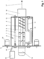
- FIG. 5 shows the device in front view.
- the horizontal dashed line marks the contour line 20 of the clay-water mixture.
Description
- Die Erfindung betrifft ein Verfahren und eine Vorrichtung zum kontinuierlichen Mischen von Lehm und lehmähnlichen Stoffen, deren Anwendung sich insbesondere für die Verarbeitung von Lehmputzen anbietet.
- Im Wohnungsbau gewinnt Lehm eine zunehmende Bedeutung als ökologischer Baustoff. Insbesondere ist Lehmputz sehr beliebt, weil er für ein angenehmes Raumklima sorgt. Seine Verarbeitung ist jedoch gegenüber konventionellen Putzen aufwendiger.
- Für die Verarbeitung des Lehms muss dieser mit Wasser vermischt werden. Das Versetzen mit Wasser und der anschließende Transport des mit Wasser versetzten Lehms an den Verarbeitungsort erfolgt bisher in zwei Arbeitsschritten. Zuerst wird der Lehm manuell oder maschinell mit Wasser vermischt und anschließend ebenfalls manuell oder maschinell an den Bestimmungsort befördert, wo er schließlich verarbeitet wird.
- Für das maschinelle Vermischen des Lehms mit Wasser werden üblicherweise Zwangsmischer verwendet.
- Ein Zwangsmischer ist beispielsweise in
DE 102 08 798 A1 offenbart. Dieser weist einen Mischbottich mit einem darin drehenden Rührwerk auf, welches Rührarme mit an deren freien Ende sitzenden Rührschaufeln aufweist. Diese Rührschaufeln reichen bis nahe an die Innenwand und den Boden des Mischbottichs heran. Um im Hinblick auf den Verschleiß und den Betriebslärm ein Klemmen von im Mischgut befindlichen Festkörpern zwischen dem Bottich und dem Rührwerk zu vermeiden, sind die Rührarme des Rührwerks als Federelemente ausgebildet. Diese Federelemente sind in besonderer Weise daran angepasst, dass die Rührarme für den Mischbetrieb eine ausreichende Steifigkeit behalten, andererseits jedoch bei Klemmungen zwischen den Rührschaufeln und der Bottich-Innenwandung bzw. dem Bottich-Boden nachgeben können. Das Wasser muss hier manuell, beispielsweise mittels eines Schlauches, dem Mischgut zugeführt werden. - Ein Verfahren zum kontinuierlichen Mischen von lehmhaltigen Stoffen und Materialien gemäss dem Oberbegriff des Anspruchs 1 und eine Vorrichtung gemäss dem Oberbegriff des Anspruchs 3 sind aus
DE 1 023 713 bekannt. Eine im unteren Bereich eines Mischbehälters angeordnete Schneckenwelle dient bei Rotation in eine erste Richtung als Bestandteil des noch zwei weitere Wellen umfassenden Knet- und Mischwerks und bei Rotation in die entgegengesetzte Richtung als Fördereinrichtung zum Austragen des Gemischs.
Der Nachteil des unabhängigen Mischens des Lehms mit Wasser und dem/der Transport/Förderung des Gemisches besteht darin, dass ein kontinuierliches Arbeiten verhindert wird; es muss der Zwangsmischer erst entleert werden, bevor er erneut mit Lehm und Wasser befüllt werden kann. Der Mischvorgang selbst dauert üblicherweise mehrere Minuten, bevor eine ausreichende Durchmischung sichergestellt werden kann. Darüber hinaus wird regelmäßig eine größere Menge an Lehm im Mischbottich mit Wasser vermengt, um diesen so selten wie möglich entleeren zu müssen. Dies erschwert jedoch die gleichmäßige Durchmischung des Lehm-Wassergemisches, wodurch sich wiederum die Mischdauer zwangsweise verlängert.
Der mit Wasser vermischte Lehm wird anschließend dem Mischbottich entnommen und einer Fördereinrichtung zugeführt, mit der der mit Wasser vermischte Lehm an seinen Bestimmungsort befördert wird. Wird das Lehm-Wassergemisch mittels einer Förderpumpe durch Schlauchleitungen transportiert, so ist es notwendig, dass der Lehm mit reichlich Wasser angemischt wird, damit das Gemisch dünnflüssig genug ist, um mit der Pumpe gefördert werden zu können.
Eine Maschine zur Vermischung von Wasser mit Mehl, die eine vorgegebene Menge Weizenmehl in einem Tank mit einem rotierenden Rührblatt verwirbelt und Wasserdampf durch in dem Rührblatt angeordnete Wasserdüsen zu dem wirbelnden Weizenmehlstaub hinzufügt, ist inJP S62 1445 A
Bei dem Einsatz von zwei getrennt arbeitenden Maschinen für das Mischen und den Transport ist zwangsläufig nachteilig, dass zwei eigenständige Maschinen betrieben, gereinigt und gewartet werden müssen. Weiterhin benötigt der Lehm, da er sehr dünnflüssig angemischt wird, lange Zeit zum Trocknen. Weiterhin besteht die Gefahr, dass er, wenn er auf Wänden dick aufgetragen wird, wegfließt. - Darüber hinaus muss bei jeder Füllung des Mischers darauf geachtet werden, dass das Mischungsverhältnis zwischen Lehm- und Wassermanege stimmt. Abweichungen im Mischungsverhältnis führen zu einer variierenden Konsistenz des Lehm-Wassergemisches zwischen den einzelnen Mischerfüllungen.
- Vorrichtungen, die den vorgenannten Nachteil, dass nicht kontinuierlich Mischgut angemischt werden kann und dass unterschiedliche Maschinen für das Anmischen und Fördern des Mischgutes benötigt werden, beseitigen, sind beispielsweise durch die in
DE 10 2007 030 458 A1 offenbarte Erfindung bekannt. Die dort beschriebene Erfindung betrifft eine Einrichtung zum kontinuierlichen und intensiven Mischen von Trockenmörtel mit Wasser, bei der ein Mischbehälter mit einer zylindrischen Mischkammer mit Flanschen und einer rotierenden Mischerwelle mit Mischwerkzeugen, einem Eingabebereich für Trockenmörtel, einer Wasserzuführeinrichtung und einem Ausgabebereich für gemischten Mörtel vorgesehen ist, wobei die Mischkammer eine Trenneinrichtung und eine Beschichtung aufweist, axial zu öffnen ist und die Wasserzuführung durch in axialer Erstreckung angeordnete Verteileröffnungen erfolgt und wobei die Mischerwelle Leiteinrichtungen, spezielle Mischwerkzeuge und Kupplungseinrichtungen aufweist, die mit einer geeigneten Antriebseinrichtung und/oder einer Mörtelpumpe in lösbarer Verbindung stehen. Die Erfindung betrifft ferner eine Einrichtung der vorgenannten Art, bei welcher die Mischerwelle des Mischers über eine Antriebswelle mit einer Fördereinrichtung eines zugehörigen Vorratsbehälters und einer Antriebseinrichtung schaltbar verbunden ist. - Dieser Vorrichtung haftet jedoch der Nachteil an, dass sich mit ihr lehmhaltige oder lehmähnliche Stoffe mit Wasser nicht ausreichend homogen mischen lassen.
-
FR 1 059 585 A - Aufgabe der Erfindung ist es, ein Verfahren und eine Vorrichtung zur Verfügung zu stellen, mit der lehmhaltige und lehmähnliche Stoffe kontinuierlich so mit Wasser vermischt werden, dass eine möglichst dickflüssige und stets gleichbleibend homogene Lehm-Wassermischung entsteht, die sich mittels einer an der Vorrichtung angeschlossenen Fördereinrichtung fördern lässt, wodurch ein kontinuierliches Arbeiten sichergestellt wird.
- Erfindungsgemäß wird die Aufgabe durch die Merkmale der unabhängigen Ansprüche 1 und 3 gelöst; Vorteilhafte Ausgestaltungen des Verfahrens und der Vorrichtung sind in den abhängigen Unteransprüchen beschrieben.
- Gemäß Anspruch 1 wird bei dem erfindungsgemäßen Verfahren zum Mischen von lehmhaltigen und lehmähnlichen Stoffen mit Wasser das Mischgut mittels einer im unteren Bereich eines Vorrats- und Mischbehälters angeordneten Dosier- und Austragswelle einer Fördereinrichtung zugeführt wird. Das Verfahren ist dadurch charakterisiert, dass durch gleichzeitige Drehbewegung von wenigstens einer parallel und oberhalb der Dosier- und Austragswelle gelagerten Seitenwelle das Mischgut aufgelockert, gemischt und in Bewegung gehalten wird, wobei dem Mischgut gleichmäßig verteilt Anmachwasser zugegeben wird, und durch die Abstimmung von Wasserzugabe und Austrag des Mischgutes eine Lehm-Wassermischung nahezu gleich bleibender Konsistenz gebildet wird, die sowohl die Dosier- und Austragswelle als auch die zumindest eine Seitenwelle fortwährend und vollständig umschließt.
- Bevorzugt ist die vertikale Ausdehnung der Lehm-Wassermischung doppelt so groß wie die größtmögliche vertikale Erstreckung der wenigstens einen Seitenwelle.
- Die Vorrichtung zur Durchführung des erfindungsgemäßen Verfahrens besteht aus einem Vorrats- und Mischbehälter, in dessen unteren Bereich sich eine Dosier- und Austragswelle befindet. Zudem besitzt die Vorrichtung eine Wasserzuführeinrichtung, über die dem Mischgut Wasser zugeführt wird. Gekennzeichnet ist die Erfindung durch zumindest eine oberhalb der Dosier- und Austragswelle angeordneten und in Längsrichtung gebogene Seitenwelle.
- Durch die permanente Drehbewegung der Seitenwellen und die kontinuierliche und regelbare Wasserzuführung wird erreicht, dass das Lehm-Wassergemisch stets die optimale Verarbeitungskonsistenz besitzt.
Durch den Austrag von mit Wasser vermischtem Mischgut durch die Austragsöffnung rutscht von oben her stets frisches, trockenes Mischgut zu der zumindest einen Seitenwelle nach. Durch die auf die Austragsgeschwindigkeit abgestimmte Wasserzuführung wird sichergestellt, dass das Lehm-Wassergemisch stets eine gleichbleibende Konsistenz aufweist.
Da das Lehm-Wassergemisch mit Hilfe der Dosier- und Austragswelle einer Fördereinrichtung zugeführt wird, kann das Gemisch dickflüssiger verarbeitet werden, als mit herkömmlichen Vorrichtungen. Dies hat den Vorteil, dass das Lehm-Wassergemisch besser an Wänden haftet und zugleich schneller durchtrocknet.
Durch den kontinuierlichen Austrag des Lehm-Wassergemisches aus dem Vorrats- und Mischbehälter ist es möglich, den Vorratsbehälter mit trockenem Lehm zu befüllen, ohne auf die Füllhöhe achten zu müssen. Dennoch hat das mit Wasser vermischte Mischgut stets die optimale Verarbeitungskonsistenz.
In einer weiteren und besonders vorteilhaften Ausgestaltungsvariante sind oberhalb der Dosier- und Austragswelle zwei Seitenwellen angeordnet, die entweder gekoppelt über einen Antrieb oder getrennt voneinander über zwei Antriebe in Drehung versetzt werden. In Abhängigkeit des verwendeten Mischguts werden die Seitenwellen mit gleichem Drehsinn oder mit entgegen gesetztem Drehsinn bewegt; die Drehgeschwindigkeit der Seitenwellen ist bevorzugt identisch. - Erfindungsgemäss ist die Seitenwelle gleichzeitig die Wasserzuführeinrichtung. Hierbei ist die Seitenwelle ein an seinen Enden verschlossenes Rohr, das Wasseraustrittsöffnungen aufweist. Das Rohr ist auf zwei Zapfen gelagert, wovon einer dem Antrieb der Seitenwelle und der andere der Wasserzuführung dient. Der Zapfen, der der Wasserzuführung dient, ist weist eine axiale Bohrung auf, die mit dem Hohlraum im Rohr in Verbindung steht. Bei Betrieb der Vorrichtung wird die zumindest eine Seitenwelle über den Wasseranschluss mit Wasser beaufschlagt. Über die in der Seitenwelle eingebrachten Wasseraustrittsöffnungen tritt das Wasser aus dieser aus und befeuchtet das Mischgut. Erfindungsgemäss befinden sich die Wasseraustrittsöffnungen, bezogen auf die Drehrichtung der Seitenwelle, im rückwärtigen Bereich der Seitenwelle. Damit wird vermieden, dass Mischgut in die Wasseraustrittsöffnungen gedrückt wird und diese unerwünscht verstopft. Die Wassermenge, die dem Lehm zugeführt wird, wird über eine Wasserdosiereinrichtung reguliert.
In einer weiteren Ausgestaltungsvariante der erfindungsgemäßen Vorrichtung wird das Wasser zum Anmischen des Lehm-Wassergemisches über in die Wände des Vorrats- und Mischbehälters eingebrachte Wasserdüsen vorgenommen.
Die Dosier- und Austragswelle weist Flügel- und Austragselementen auf; durch Drehung der Dosier- und Austragswelle wird das sie umgebende Lehm-Wassergemisch in Richtung der Austragsöffnung bewegt und durch diese hindurch aus dem Vorrats- und Mischbehälter hinaus in die Fördereinrichtung (Pumpe) gedrückt. Die Form, Anzahl und Vorrichtung der Flügelelemente ist abhängig von dem verwendeten Mischgut.
Mit dem erfindungsgemäßen Verfahren und der zugehörigen Vorrichtung wird in besonders vorteilhafter Weise ein kontinuierliches Arbeiten - Befüllen des Vorrats- und Mischbehälters mit Lehm, Mischen des Lehms mit Wasser und Fördern und Verarbeiten des Mischgutes - mit nur einer Maschine (monomaschinelle Verarbeitung) ermöglicht. Zudem wird sichergestellt, dass das Lehm Wassergemisch eine gleichbleibende Konsistenz aufweist.
Darüber hinaus zeichnet sich die erfindungsgemäße Lehmputzmaschine durch eine sehr geringe Baugröße und Leistungsaufnahme aus; im Vergleich zu bekannten Lösungen hat die Vorrichtung eine nur in etwa halb so große Leistungsaufnahme (ca. 3 bis 4 KW).
Darüber hinaus ist der Erfindungsgegenstand auch in zunächst nicht naheliegenden Anwendungsbereiche übertragbar, in denen Stoffe aber auch kontinuierlich gemischt und gefördert werden müssen; als Beispiel seien Backbetriebe genannt. - Die Erfindung wird nachfolgend anhand eines Ausführungsbeispiels mit den
Figuren 1 bis 5 erläutert; hierbei zeigt: - Fig. 1:
- die Vorrichtung in Draufsicht;
- Fig. 2:
- eine Seitenwelle im Längsschnitt;
- Fig. 3:
- eine Seitenwelle in Seitenansicht;
- Fig. 4:
- die Vorrichtung in Rückansicht;
- Fig. 5:
- die Vorrichtung in Vorderansicht.
- Aus
Fig. 1 ist der Vorrats- und Mischbehälter 1, der von zwei Längswänden 2, zwei Querwänden 3 und einem Boden 4 gebildet wird, ersichtlich. Im Boden 4 erstreckt sich in Längsrichtung der Sumpf 5, in dem parallel beabstandet die Dosier- und Austragswelle 6 mit den Flügelelementen 7 und dem Förderelement 8 angeordnet ist. Seitlich versetzt und oberhalb der Dosier- und Austragswelle 6 befinden sich zwei Seitenwellen 9 und 10, welche um 90° zueinander verdreht sind. - Die
Figuren 2 und 3 zeigen eine zweibögige, hohle Seitenwelle. In den Bögen sind eine beziehungsweise zwei Wasseraustrittsöffnungen 11 eingebracht. Innerhalb der Bögen der Seitenwelle befinden sich die Flügelelemente 12. Über den Wasseranschluss 13 wird die Seitenwelle mit Wasser beaufschlagt; der Wasseranschluss 13 wird wiederum über die Wasseranschlussleitung 14 und die Wasserdosiereinrichtung 15 mit dem Anmachwasser versorgt. - Weiterhin sind in
Fig. 1 der Antrieb 18 für die Austragswelle 6 und zwei Antriebe 19, die jeweils eine Seitenwelle 9 bzw. 10 in Drehung versetzen, dargestellt. Durch Drehung der Dosier- und Austragswelle 6 wird das mit Wasser vermischte Mischgut der Fördereinrichtung 16 (Pumpe) zugeführt. Der Pfeil 17 verdeutlicht die Förderichtung des Mischgutes. - In
Fig. 4 ist die Lehmputzmaschine - wie beschrieben - zu sehen; auf die Darstellung der Wasseranschlussleitung 14, der Wasserdosiereinrichtung 15 und des Antriebs 18 wurde - der Übersichtlichkeit wegen - verzichtet. -
Figur 5 zeigt die Vorrichtung in Vorderansicht. Die horizontal verlaufende gestrichelte Linie markiert die Höhenlinie 20 des Lehm-Wassergemischs. -
- 1
- Vorrats- und Mischbehälter
- 2
- Längswand
- 3
- Querwand
- 4
- Boden
- 5
- Sumpf
- 6
- Dosier- und Austragswelle
- 7
- Flügelelement
- 8
- Förderelement
- 9
- Erste Seitenwelle
- 10
- Zweite Seitenwelle
- 11
- Wasseraustrittsöffnung
- 12
- Flügelelement
- 13
- Wasseranschluss
- 14
- Wasseranschlussleitung
- 15
- Wasserdosiereinrichtung
- 16
- Fördereinrichtung
- 17
- Förderrichtung
- 18
- Antrieb Austragswelle
- 19
- Antrieb Seitenwelle
- 20
- Höhenlinie
Claims (12)
- Verfahren zum kontinuierlichen Mischen von lehmhaltigen Stoffen und Materialien mit lehmähnlichem Mischverhalten mit Wasser, bei dem das Mischgut mittels einer im unteren Bereich eines Vorrats- und Mischbehälters (1) angeordneten Dosier- und Austragswelle (6) kontinuierlich einer Fördereinrichtung (16) zugeführt wird, wobei durch wenigstens eine parallel und oberhalb der Dosier- und Austragswelle (6) gelagerte, in Längsrichtung gebogene Seitenwelle (9) das Mischgut aufgelockert, gemischt und in Bewegung gehalten wird, dadurch gekennzeichnet, dass dem Mischgut zumindest mittels der Seitenwelle (9), die an ihrem bezüglich ihrer Drehrichtung rückwärtigen Bereich Wasseraustrittsöffnungen (11) aufweist, gleichmäßig verteilt Anmachwasser zugegeben wird, und durch die Abstimmung von Wasserzugabe und Austrag des Mischgutes eine Lehm-Wassermischung nahezu gleich bleibender Konsistenz gebildet wird, die sowohl die Dosier- und Austragswelle (6) als auch die zumindest eine Seitenwelle (9) fortwährend und vollständig umschließt.
- Verfahren nach Anspruch 1, dadurch gekennzeichnet, dass die vertikale Ausdehnung der Lehm-Wassermischung doppelt so groß ist wie die größtmögliche vertikale Erstreckung der wenigstens einen Seitenwelle.
- Vorrichtung geeignet zur Durchführung des Verfahrens nach Anspruch 1 mit einer im unteren Bereich eines Vorrats- und Mischbehälter (1) befindlichen Dosier- und Austragswelle (6) und zumindest einer Wasserzuführeinrichtung, dadurch gekennzeichnet, dass parallel und oberhalb der Dosier- und Austragswelle (6) zumindest eine in Längsrichtung gebogene Seitenwelle (9), die Wasseraustrittsöffnungen (11) zum Zuführen von Wasser aufweist, angeordnet ist, wobei die Wasseraustrittsöffnungen (11) im, bezogen auf die bestimmungsgemäße Drehrichtung im Betrieb, rückwärtigen Bereich der Seitenwelle (9) eingebracht sind.
- Vorrichtung nach Anspruch 3, dadurch gekennzeichnet, dass die dem Mischen des Mischguts dienende gebogene Seitenwelle (9) als ein an seinen Enden verschlossenes Rohr mit Wasseraustrittsöffnungen (11) ausgeführt ist, das auf zwei mit ihm fest verbundenen Zapfen gelagert ist, wobei ein Zapfen zylindrisch durchbrochen ist und als Wasseranschluss (13) dient und der andere die Aufnahme für den Antrieb der Seitenwelle darstellt.
- Vorrichtung nach Anspruch 3 oder 4, dadurch gekennzeichnet, dass die Seitenwelle (9) gleich große wellenförmige Abschnitte aufweist.
- Vorrichtung nach einem der Ansprüche 3 bis 5, dadurch gekennzeichnet, dass die Seitenwelle (9) mäanderförmig ausgebildet ist.
- Vorrichtung nach einem der Ansprüche 3 bis 6, dadurch gekennzeichnet, dass sie zusätzlich zumindest eine in einer der Behälterwände (2; 3) eingebrachte Wasserdüse aufweist.
- Vorrichtung nach einem der Ansprüche 3 bis 7, dadurch gekennzeichnet, dass die wenigstens eine Seitenwelle (9) sowohl zur Dosiereinrichtung, als auch zur Längswandung (2) des Vorrats- und Mischbehälters (1) einen Abstand von mindestens 1 mm aufweist.
- Vorrichtung nach einem der Ansprüche 3 bis 8, dadurch gekennzeichnet, dass der Wasseranschluss (13) über eine flexible oder starre Wasseranschlussleitung (14) mit einer Wasserdosiereinrichtung (15) für das Anmachwasser verbunden ist.
- Vorrichtung nach einem der Ansprüche 3 bis 9, dadurch gekennzeichnet, dass an der Seitenwelle (9) wenigstens ein Flügelelement (12), das als Mischwerkzeug dient, angebracht ist.
- Vorrichtung nach einem der Ansprüche 3 bis 10, dadurch gekennzeichnet, dass parallel zu und oberhalb der Dosier- und Austragswelle (6) und ebenfalls parallel zu der ersten Seitenwelle (9) eine weitere Seitenwelle (10) angeordnet ist.
- Vorrichtung nach Anspruch 11, dadurch gekennzeichnet, dass die Rotationen der beiden Seitenwellen (9; 10) im Betrieb der Vorrichtung synchronisiert sind.
Priority Applications (2)
| Application Number | Priority Date | Filing Date | Title |
|---|---|---|---|
| PL10000095T PL2343170T3 (pl) | 2010-01-08 | 2010-01-08 | Sposób i urządzenie do ciągłego mieszania surowców zawierających glinę i materiałów wykazujących podobne do gliny zachowanie podczas mieszania |
| EP10000095.9A EP2343170B1 (de) | 2010-01-08 | 2010-01-08 | Verfahren und Vorrichtung zum kontinuierlichen Mischen von lehmhaltigen Stoffen und Materialien mit lehmähnlichem Mischverhalten |
Applications Claiming Priority (1)
| Application Number | Priority Date | Filing Date | Title |
|---|---|---|---|
| EP10000095.9A EP2343170B1 (de) | 2010-01-08 | 2010-01-08 | Verfahren und Vorrichtung zum kontinuierlichen Mischen von lehmhaltigen Stoffen und Materialien mit lehmähnlichem Mischverhalten |
Publications (2)
| Publication Number | Publication Date |
|---|---|
| EP2343170A1 EP2343170A1 (de) | 2011-07-13 |
| EP2343170B1 true EP2343170B1 (de) | 2018-09-19 |
Family
ID=42668185
Family Applications (1)
| Application Number | Title | Priority Date | Filing Date |
|---|---|---|---|
| EP10000095.9A Active EP2343170B1 (de) | 2010-01-08 | 2010-01-08 | Verfahren und Vorrichtung zum kontinuierlichen Mischen von lehmhaltigen Stoffen und Materialien mit lehmähnlichem Mischverhalten |
Country Status (2)
| Country | Link |
|---|---|
| EP (1) | EP2343170B1 (de) |
| PL (1) | PL2343170T3 (de) |
Families Citing this family (4)
| Publication number | Priority date | Publication date | Assignee | Title |
|---|---|---|---|---|
| CN108858754A (zh) * | 2018-07-25 | 2018-11-23 | 陈婷 | 一种路桥建设用混凝土加工设备 |
| CN109176879A (zh) * | 2018-08-15 | 2019-01-11 | 嘉善中嘉化工有限公司 | 一种多功能搅拌机 |
| CN113926331A (zh) * | 2021-11-02 | 2022-01-14 | 山东金格瑞机械有限公司 | 一种饲料制作装置 |
| CN114534618B (zh) * | 2022-04-25 | 2022-07-29 | 东营华亚国联航空燃料有限公司 | 一种提高抗静电剂准确量的在线加注装置 |
Citations (2)
| Publication number | Priority date | Publication date | Assignee | Title |
|---|---|---|---|---|
| FR1059585A (fr) * | 1952-07-09 | 1954-03-25 | Materiel Ceramique Moderne | Groupe destiné à l'humidification, au malaxage et moulage en continu sous vide des pâtes céramiques ou autres |
| JPS621445A (ja) * | 1985-06-27 | 1987-01-07 | Keiichiro Murofushi | 粉体に対する水の混合方法及びこれに使用する混合機 |
Family Cites Families (6)
| Publication number | Priority date | Publication date | Assignee | Title |
|---|---|---|---|---|
| DE1023713B (de) * | 1955-03-25 | 1958-01-30 | Femmegina Ruemcke Geb Slik | Verfahren und Vorrichtung zum Kneten und Mischen von keramischen od. dgl. Massen |
| ATE20321T1 (de) * | 1980-10-31 | 1986-06-15 | Mathis Systemtechnik Gmbh | Verfahren und vorrichtung zum kontinuierlichen anmachen von moertel, putz oder dgl. baustoff oder material. |
| FR2598349B1 (fr) * | 1986-05-07 | 1988-09-23 | Gilles Pierre | Procede de fabrication de murs en pises, ou terre stabilisee, machine a projeter adaptee a sa mise en oeuvre, et mur ainsi obtenu |
| DE19857775A1 (de) * | 1998-12-04 | 2000-06-08 | Ver Energiewerke Ag | Vorrichtung zur Vermischung und Behandlung von trockenen Schüttgütern und wasserhaltigen Substanzen |
| DE10208798B4 (de) | 2002-03-01 | 2007-04-26 | Atika Gmbh & Co. Kg | Zwangsmischer |
| DE102006049171B4 (de) | 2006-10-18 | 2009-01-15 | Werner Dutschmann | Einrichtung zum kontinuierlichen und intensiven Mischen von Trockenmörtel |
-
2010
- 2010-01-08 EP EP10000095.9A patent/EP2343170B1/de active Active
- 2010-01-08 PL PL10000095T patent/PL2343170T3/pl unknown
Patent Citations (2)
| Publication number | Priority date | Publication date | Assignee | Title |
|---|---|---|---|---|
| FR1059585A (fr) * | 1952-07-09 | 1954-03-25 | Materiel Ceramique Moderne | Groupe destiné à l'humidification, au malaxage et moulage en continu sous vide des pâtes céramiques ou autres |
| JPS621445A (ja) * | 1985-06-27 | 1987-01-07 | Keiichiro Murofushi | 粉体に対する水の混合方法及びこれに使用する混合機 |
Also Published As
| Publication number | Publication date |
|---|---|
| EP2343170A1 (de) | 2011-07-13 |
| PL2343170T3 (pl) | 2019-05-31 |
Similar Documents
| Publication | Publication Date | Title |
|---|---|---|
| DE102006049171B4 (de) | Einrichtung zum kontinuierlichen und intensiven Mischen von Trockenmörtel | |
| EP2722103A2 (de) | Zwangsmischer mit Selbstreinigungsfunktion und Verwendung von Lufteinlässen hierfür | |
| WO2008052530A2 (de) | Misch- und fördervorrichtung für mörtel | |
| DE2637558A1 (de) | Verfahren und vorrichtung zur erzeugung eines kontinuierlichen materialstroms | |
| DE3809661C2 (de) | Vorrichtung zum kontinuierlichen Mischen eines Baustoffs | |
| DE2920025A1 (de) | Verfahren und vorrichtung zum kontinuierlichen mischen eines trockenfertigmoertels | |
| EP2343170B1 (de) | Verfahren und Vorrichtung zum kontinuierlichen Mischen von lehmhaltigen Stoffen und Materialien mit lehmähnlichem Mischverhalten | |
| EP3656462A1 (de) | Dosier- und mischsystem und verfahren zu seinem betrieb | |
| DE4318177C2 (de) | Vorrichtung zur baustellenseitigen Herstellung von pumpfähigen Mörtelmassen | |
| EP0584573B1 (de) | Vorrichtung zur baustellenseitigen Herstellung von pumpfähigen Mörtelmassen | |
| DE102005005394B4 (de) | Pump- und Mischvorrichtung für pulver- bzw. rieselförmige Medien sowie System zur Bereitstellung pastöser Medien für Bauzwecke | |
| EP1541239B1 (de) | Vorrichtung zum Zerreissen von Feststoffen, Zumischen von Flüssigkeit und Fördern der erzeugten Suspension in eine Verarbeitungsanlage | |
| DE102009023546B4 (de) | Dosiervorrichtung zum Einbringen eines pulverförmigen Mediums in eine Flüssigkeit | |
| DE1782125B2 (de) | Vorrichtung zum kontinuierlichen mischen und kneten plastischer fuell- und spachtelmassen o dgl | |
| EP3334519B1 (de) | Vorrichtung und verfahren zum dispergieren mindestens einer substanz in einem fluid | |
| DE19757734A1 (de) | Verfahren und Mischer zum Herstellen farbiger Mörtelmassen | |
| EP3154711A1 (de) | Vorrichtung zur konfektionierung und auftragung von kleber | |
| DE102006043596B3 (de) | Fördervorrichtung | |
| DE4127873C2 (de) | Kneteinrichtung für eine zu knetende Masse | |
| DE3011410A1 (de) | Maschine zum kontinuierlichen mischen und verspruehen von stoffen bzw. erzeugnissen fuer das verputzen und ueberziehen von gemauerten waenden | |
| DE19514384C2 (de) | Misch- oder Dispergiervorrichtung mit einem Leitgehäuse | |
| DE2420115A1 (de) | Maschine zum zerkleinern und mischen von materialien | |
| DE2953699A1 (de) | ||
| DE3340603A1 (de) | Vorrichtung zum kontinuierlichen herstellen, foerdern und pumpen von putz- oder mauermoertel | |
| DE19812154A1 (de) | Vorrichtung zum Mischen und Fördern von Stoffgemischen |
Legal Events
| Date | Code | Title | Description |
|---|---|---|---|
| PUAI | Public reference made under article 153(3) epc to a published international application that has entered the european phase |
Free format text: ORIGINAL CODE: 0009012 |
|
| AK | Designated contracting states |
Kind code of ref document: A1 Designated state(s): AT BE BG CH CY CZ DE DK EE ES FI FR GB GR HR HU IE IS IT LI LT LU LV MC MK MT NL NO PL PT RO SE SI SK SM TR |
|
| AX | Request for extension of the european patent |
Extension state: AL BA RS |
|
| 17P | Request for examination filed |
Effective date: 20120109 |
|
| 17Q | First examination report despatched |
Effective date: 20150617 |
|
| RIC1 | Information provided on ipc code assigned before grant |
Ipc: B01F 7/02 20060101ALI20151006BHEP Ipc: B01F 7/04 20060101ALI20151006BHEP Ipc: B01F 7/00 20060101ALI20151006BHEP Ipc: B01F 15/02 20060101ALI20151006BHEP Ipc: B28C 5/12 20060101AFI20151006BHEP Ipc: B28C 5/14 20060101ALI20151006BHEP |
|
| GRAP | Despatch of communication of intention to grant a patent |
Free format text: ORIGINAL CODE: EPIDOSNIGR1 |
|
| STAA | Information on the status of an ep patent application or granted ep patent |
Free format text: STATUS: GRANT OF PATENT IS INTENDED |
|
| INTG | Intention to grant announced |
Effective date: 20180412 |
|
| GRAS | Grant fee paid |
Free format text: ORIGINAL CODE: EPIDOSNIGR3 |
|
| GRAA | (expected) grant |
Free format text: ORIGINAL CODE: 0009210 |
|
| STAA | Information on the status of an ep patent application or granted ep patent |
Free format text: STATUS: THE PATENT HAS BEEN GRANTED |
|
| AK | Designated contracting states |
Kind code of ref document: B1 Designated state(s): AT BE BG CH CY CZ DE DK EE ES FI FR GB GR HR HU IE IS IT LI LT LU LV MC MK MT NL NO PL PT RO SE SI SK SM TR |
|
| REG | Reference to a national code |
Ref country code: GB Ref legal event code: FG4D Free format text: NOT ENGLISH |
|
| REG | Reference to a national code |
Ref country code: CH Ref legal event code: EP |
|
| REG | Reference to a national code |
Ref country code: AT Ref legal event code: REF Ref document number: 1042721 Country of ref document: AT Kind code of ref document: T Effective date: 20181015 |
|
| REG | Reference to a national code |
Ref country code: IE Ref legal event code: FG4D Free format text: LANGUAGE OF EP DOCUMENT: GERMAN |
|
| REG | Reference to a national code |
Ref country code: DE Ref legal event code: R096 Ref document number: 502010015372 Country of ref document: DE |
|
| REG | Reference to a national code |
Ref country code: NL Ref legal event code: MP Effective date: 20180919 |
|
| PG25 | Lapsed in a contracting state [announced via postgrant information from national office to epo] |
Ref country code: BG Free format text: LAPSE BECAUSE OF FAILURE TO SUBMIT A TRANSLATION OF THE DESCRIPTION OR TO PAY THE FEE WITHIN THE PRESCRIBED TIME-LIMIT Effective date: 20181219 Ref country code: SE Free format text: LAPSE BECAUSE OF FAILURE TO SUBMIT A TRANSLATION OF THE DESCRIPTION OR TO PAY THE FEE WITHIN THE PRESCRIBED TIME-LIMIT Effective date: 20180919 Ref country code: NO Free format text: LAPSE BECAUSE OF FAILURE TO SUBMIT A TRANSLATION OF THE DESCRIPTION OR TO PAY THE FEE WITHIN THE PRESCRIBED TIME-LIMIT Effective date: 20181219 Ref country code: GR Free format text: LAPSE BECAUSE OF FAILURE TO SUBMIT A TRANSLATION OF THE DESCRIPTION OR TO PAY THE FEE WITHIN THE PRESCRIBED TIME-LIMIT Effective date: 20181220 Ref country code: LT Free format text: LAPSE BECAUSE OF FAILURE TO SUBMIT A TRANSLATION OF THE DESCRIPTION OR TO PAY THE FEE WITHIN THE PRESCRIBED TIME-LIMIT Effective date: 20180919 Ref country code: FI Free format text: LAPSE BECAUSE OF FAILURE TO SUBMIT A TRANSLATION OF THE DESCRIPTION OR TO PAY THE FEE WITHIN THE PRESCRIBED TIME-LIMIT Effective date: 20180919 |
|
| REG | Reference to a national code |
Ref country code: LT Ref legal event code: MG4D |
|
| PG25 | Lapsed in a contracting state [announced via postgrant information from national office to epo] |
Ref country code: HR Free format text: LAPSE BECAUSE OF FAILURE TO SUBMIT A TRANSLATION OF THE DESCRIPTION OR TO PAY THE FEE WITHIN THE PRESCRIBED TIME-LIMIT Effective date: 20180919 Ref country code: LV Free format text: LAPSE BECAUSE OF FAILURE TO SUBMIT A TRANSLATION OF THE DESCRIPTION OR TO PAY THE FEE WITHIN THE PRESCRIBED TIME-LIMIT Effective date: 20180919 |
|
| PG25 | Lapsed in a contracting state [announced via postgrant information from national office to epo] |
Ref country code: RO Free format text: LAPSE BECAUSE OF FAILURE TO SUBMIT A TRANSLATION OF THE DESCRIPTION OR TO PAY THE FEE WITHIN THE PRESCRIBED TIME-LIMIT Effective date: 20180919 Ref country code: EE Free format text: LAPSE BECAUSE OF FAILURE TO SUBMIT A TRANSLATION OF THE DESCRIPTION OR TO PAY THE FEE WITHIN THE PRESCRIBED TIME-LIMIT Effective date: 20180919 Ref country code: IT Free format text: LAPSE BECAUSE OF FAILURE TO SUBMIT A TRANSLATION OF THE DESCRIPTION OR TO PAY THE FEE WITHIN THE PRESCRIBED TIME-LIMIT Effective date: 20180919 Ref country code: ES Free format text: LAPSE BECAUSE OF FAILURE TO SUBMIT A TRANSLATION OF THE DESCRIPTION OR TO PAY THE FEE WITHIN THE PRESCRIBED TIME-LIMIT Effective date: 20180919 Ref country code: IS Free format text: LAPSE BECAUSE OF FAILURE TO SUBMIT A TRANSLATION OF THE DESCRIPTION OR TO PAY THE FEE WITHIN THE PRESCRIBED TIME-LIMIT Effective date: 20190119 Ref country code: NL Free format text: LAPSE BECAUSE OF FAILURE TO SUBMIT A TRANSLATION OF THE DESCRIPTION OR TO PAY THE FEE WITHIN THE PRESCRIBED TIME-LIMIT Effective date: 20180919 Ref country code: CZ Free format text: LAPSE BECAUSE OF FAILURE TO SUBMIT A TRANSLATION OF THE DESCRIPTION OR TO PAY THE FEE WITHIN THE PRESCRIBED TIME-LIMIT Effective date: 20180919 |
|
| PG25 | Lapsed in a contracting state [announced via postgrant information from national office to epo] |
Ref country code: SK Free format text: LAPSE BECAUSE OF FAILURE TO SUBMIT A TRANSLATION OF THE DESCRIPTION OR TO PAY THE FEE WITHIN THE PRESCRIBED TIME-LIMIT Effective date: 20180919 Ref country code: PT Free format text: LAPSE BECAUSE OF FAILURE TO SUBMIT A TRANSLATION OF THE DESCRIPTION OR TO PAY THE FEE WITHIN THE PRESCRIBED TIME-LIMIT Effective date: 20190119 Ref country code: SM Free format text: LAPSE BECAUSE OF FAILURE TO SUBMIT A TRANSLATION OF THE DESCRIPTION OR TO PAY THE FEE WITHIN THE PRESCRIBED TIME-LIMIT Effective date: 20180919 |
|
| REG | Reference to a national code |
Ref country code: DE Ref legal event code: R097 Ref document number: 502010015372 Country of ref document: DE |
|
| PLBE | No opposition filed within time limit |
Free format text: ORIGINAL CODE: 0009261 |
|
| STAA | Information on the status of an ep patent application or granted ep patent |
Free format text: STATUS: NO OPPOSITION FILED WITHIN TIME LIMIT |
|
| PG25 | Lapsed in a contracting state [announced via postgrant information from national office to epo] |
Ref country code: DK Free format text: LAPSE BECAUSE OF FAILURE TO SUBMIT A TRANSLATION OF THE DESCRIPTION OR TO PAY THE FEE WITHIN THE PRESCRIBED TIME-LIMIT Effective date: 20180919 |
|
| 26N | No opposition filed |
Effective date: 20190620 |
|
| PG25 | Lapsed in a contracting state [announced via postgrant information from national office to epo] |
Ref country code: MC Free format text: LAPSE BECAUSE OF FAILURE TO SUBMIT A TRANSLATION OF THE DESCRIPTION OR TO PAY THE FEE WITHIN THE PRESCRIBED TIME-LIMIT Effective date: 20180919 |
|
| REG | Reference to a national code |
Ref country code: CH Ref legal event code: PL |
|
| GBPC | Gb: european patent ceased through non-payment of renewal fee |
Effective date: 20190108 |
|
| PG25 | Lapsed in a contracting state [announced via postgrant information from national office to epo] |
Ref country code: LU Free format text: LAPSE BECAUSE OF NON-PAYMENT OF DUE FEES Effective date: 20190108 |
|
| REG | Reference to a national code |
Ref country code: BE Ref legal event code: MM Effective date: 20190131 |
|
| REG | Reference to a national code |
Ref country code: IE Ref legal event code: MM4A |
|
| PG25 | Lapsed in a contracting state [announced via postgrant information from national office to epo] |
Ref country code: FR Free format text: LAPSE BECAUSE OF NON-PAYMENT OF DUE FEES Effective date: 20190131 Ref country code: SI Free format text: LAPSE BECAUSE OF FAILURE TO SUBMIT A TRANSLATION OF THE DESCRIPTION OR TO PAY THE FEE WITHIN THE PRESCRIBED TIME-LIMIT Effective date: 20180919 |
|
| PG25 | Lapsed in a contracting state [announced via postgrant information from national office to epo] |
Ref country code: BE Free format text: LAPSE BECAUSE OF NON-PAYMENT OF DUE FEES Effective date: 20190131 |
|
| PG25 | Lapsed in a contracting state [announced via postgrant information from national office to epo] |
Ref country code: CH Free format text: LAPSE BECAUSE OF NON-PAYMENT OF DUE FEES Effective date: 20190131 Ref country code: GB Free format text: LAPSE BECAUSE OF NON-PAYMENT OF DUE FEES Effective date: 20190108 Ref country code: LI Free format text: LAPSE BECAUSE OF NON-PAYMENT OF DUE FEES Effective date: 20190131 |
|
| PG25 | Lapsed in a contracting state [announced via postgrant information from national office to epo] |
Ref country code: IE Free format text: LAPSE BECAUSE OF NON-PAYMENT OF DUE FEES Effective date: 20190108 |
|
| PG25 | Lapsed in a contracting state [announced via postgrant information from national office to epo] |
Ref country code: TR Free format text: LAPSE BECAUSE OF FAILURE TO SUBMIT A TRANSLATION OF THE DESCRIPTION OR TO PAY THE FEE WITHIN THE PRESCRIBED TIME-LIMIT Effective date: 20180919 |
|
| PG25 | Lapsed in a contracting state [announced via postgrant information from national office to epo] |
Ref country code: MT Free format text: LAPSE BECAUSE OF FAILURE TO SUBMIT A TRANSLATION OF THE DESCRIPTION OR TO PAY THE FEE WITHIN THE PRESCRIBED TIME-LIMIT Effective date: 20180919 |
|
| PG25 | Lapsed in a contracting state [announced via postgrant information from national office to epo] |
Ref country code: CY Free format text: LAPSE BECAUSE OF FAILURE TO SUBMIT A TRANSLATION OF THE DESCRIPTION OR TO PAY THE FEE WITHIN THE PRESCRIBED TIME-LIMIT Effective date: 20180919 |
|
| PG25 | Lapsed in a contracting state [announced via postgrant information from national office to epo] |
Ref country code: HU Free format text: LAPSE BECAUSE OF FAILURE TO SUBMIT A TRANSLATION OF THE DESCRIPTION OR TO PAY THE FEE WITHIN THE PRESCRIBED TIME-LIMIT; INVALID AB INITIO Effective date: 20100108 |
|
| REG | Reference to a national code |
Ref country code: DE Ref legal event code: R082 Ref document number: 502010015372 Country of ref document: DE Representative=s name: WERNER, ANDRE, DR., DE |
|
| PG25 | Lapsed in a contracting state [announced via postgrant information from national office to epo] |
Ref country code: MK Free format text: LAPSE BECAUSE OF FAILURE TO SUBMIT A TRANSLATION OF THE DESCRIPTION OR TO PAY THE FEE WITHIN THE PRESCRIBED TIME-LIMIT Effective date: 20180919 |
|
| PGFP | Annual fee paid to national office [announced via postgrant information from national office to epo] |
Ref country code: AT Payment date: 20230118 Year of fee payment: 14 |
|
| PGFP | Annual fee paid to national office [announced via postgrant information from national office to epo] |
Ref country code: PL Payment date: 20230130 Year of fee payment: 14 Ref country code: DE Payment date: 20230109 Year of fee payment: 14 |
|
| PGFP | Annual fee paid to national office [announced via postgrant information from national office to epo] |
Ref country code: PL Payment date: 20231227 Year of fee payment: 15 |
|
| PGFP | Annual fee paid to national office [announced via postgrant information from national office to epo] |
Ref country code: AT Payment date: 20240118 Year of fee payment: 15 |