EP2342136B1 - Flaschennaht- und embossingausrichtung - Google Patents
Flaschennaht- und embossingausrichtung Download PDFInfo
- Publication number
- EP2342136B1 EP2342136B1 EP09751791.6A EP09751791A EP2342136B1 EP 2342136 B1 EP2342136 B1 EP 2342136B1 EP 09751791 A EP09751791 A EP 09751791A EP 2342136 B1 EP2342136 B1 EP 2342136B1
- Authority
- EP
- European Patent Office
- Prior art keywords
- light
- container
- registration system
- lighting unit
- container wall
- Prior art date
- Legal status (The legal status is an assumption and is not a legal conclusion. Google has not performed a legal analysis and makes no representation as to the accuracy of the status listed.)
- Active
Links
Images


Classifications
-
- B—PERFORMING OPERATIONS; TRANSPORTING
- B65—CONVEYING; PACKING; STORING; HANDLING THIN OR FILAMENTARY MATERIAL
- B65C—LABELLING OR TAGGING MACHINES, APPARATUS, OR PROCESSES
- B65C9/00—Details of labelling machines or apparatus
- B65C9/06—Devices for presenting articles in predetermined attitude or position at labelling station
- B65C9/067—Devices for presenting articles in predetermined attitude or position at labelling station for orienting articles having irregularities, e.g. holes, spots or markings, e.g. labels or imprints, the irregularities or markings being detected
-
- G—PHYSICS
- G01—MEASURING; TESTING
- G01N—INVESTIGATING OR ANALYSING MATERIALS BY DETERMINING THEIR CHEMICAL OR PHYSICAL PROPERTIES
- G01N21/00—Investigating or analysing materials by the use of optical means, i.e. using sub-millimetre waves, infrared, visible or ultraviolet light
- G01N21/84—Systems specially adapted for particular applications
- G01N21/88—Investigating the presence of flaws or contamination
- G01N21/90—Investigating the presence of flaws or contamination in a container or its contents
- G01N21/9036—Investigating the presence of flaws or contamination in a container or its contents using arrays of emitters or receivers
-
- G—PHYSICS
- G01—MEASURING; TESTING
- G01N—INVESTIGATING OR ANALYSING MATERIALS BY DETERMINING THEIR CHEMICAL OR PHYSICAL PROPERTIES
- G01N21/00—Investigating or analysing materials by the use of optical means, i.e. using sub-millimetre waves, infrared, visible or ultraviolet light
- G01N21/84—Systems specially adapted for particular applications
- G01N21/88—Investigating the presence of flaws or contamination
- G01N21/90—Investigating the presence of flaws or contamination in a container or its contents
- G01N21/9045—Inspection of ornamented or stippled container walls
Definitions
- the invention relates to a detection system for detecting bottles or the like containers, according to the preamble of claim 1 and as shown in EP 1 628 241 A1 known.
- Such containers may be used in the nature of bottles or the like for liquids, for example for drinks.
- the containers may be made of a transparent, translucent or opaque material, for example of glass or of a translucent plastic, e.g. PET and have a shiny surface.
- the containers may have different colors.
- the containers are fed to a labeling machine in which a label in a predetermined and repeatable position should always be oriented identically to external position or design features or embossings on the outside of the container.
- the label should not only be aligned correctly to embossing or other features, but should be arranged as possible wrinkle-free or without elevations and / or depressions on the container.
- containers may have two vertically extending, directly opposite bottle seams or only one bottle seam.
- the label is not applied to one of the bottle seams or on the bottle seam or container seam, as this disturbs the appearance of the label or the container to the effect that the label in the area of the pocket stitching a fold (collection / Well), so that the impression arises that the label is applied with poor quality on the container. This may result in end users avoiding the product.
- the invention is therefore based on the object of specifying a detection system of the type mentioned above, which recognizes features on the container by simple means, so that the label can not be applied to a bottle seam and / or arranged correctly aligned to embossing on the container.
- the object is achieved by a detection system having the features of claim 1.
- the lighting unit is designed so that vertically aligned light beams are projected onto the container wall area.
- the illumination unit has a carrier element with a light surface oriented toward the container.
- At least one conductor track is arranged on the light surface, on which the light sources are arranged at a distance from each other in a vertically oriented manner.
- the conductor track is preferably flexible, that is to say bendable, and has vertically arranged receiving strips for the light sources, so that a strip-shaped pattern is projected onto the container wall region.
- the light sources can be embodied by way of example as LED light sources. Of course, the light sources can also be designed as an infrared light source.
- the light sources are pulsed, wherein the optical arrangement or the at least one camera is synchronized with the light source.
- the carrier element or the light surface is designed in the manner of a circular cutout which at least partially surrounds the container to be inspected or to be detected, but is axially spaced therefrom.
- a single printed conductor with light sources arranged thereon can be arranged on the light surface. It is also conceivable, however, to arrange a plurality of interconnects, preferably two interconnects with light sources arranged thereon, on the light surface, wherein the interconnects are expediently arranged one above the other, and wherein the individual light source rows or strips may advantageously have a lateral offset from one another.
- the optical arrangement has a plurality of, preferably three cameras, which are arranged in a favorable manner correlating to the striped pattern projected onto the container wall region such that the entire container wall region irradiated by the light sources can be received.
- at least a range of about 40% of the total circumference of the container of the optical arrangement is receivable.
- the optical Arrangement with respect to the lighting unit arranged appropriately offset in height.
- the detection system is preferably assigned to a labeling machine which has a labeling star.
- the support member may be made of other suitable materials.
- the conductor track or the printed conductors can be fixed in a suitable stationary location, for example, glued to their back, to name just one example of attachment.
- the at least one camera preferably all cameras, with an optical lens, preferably in the embodiment as a cylindrical lens, in order to optically spread the striped pattern projected onto the container wall region or the vertical line structure over the entire vertical detection region.
- the optical lens may also be implemented as a Fresnel lens, to name just another suitable example of an optical lens.
- optical lens By means of the advantageously provided optical lens, a higher optical resolution of the detection system can be achieved, since the line structure propagates substantially finer over the entire detection range of the optical detection system.
- this also applies to the case of the offset of the two conductor tracks or the light source rows or strips arranged thereon.
- a targeted vertical striped pattern is projected onto the container body or onto the container wall region.
- the advantageous arrangement of the light sources generated in the "total reflection” an image of the entire lighting unit or those light sources in strips or vertically arranged lines.
- the arrangement of these lines thus reflects the surface of the container to be detected or the container wall area. If no changes, for example a bottle seam, are arranged on the container wall or on the container wall region to be detected, the lines are always aligned in the same way regardless of container rotations or container positions in relation to one another. If the bottle seam now falls into this line structure, their number and arrangement will change. For example, a change in line mapping occurs.
- an absolutely exact position of the container seam can be determined so advantageous regardless of container contents and container color.
- two detection systems can be provided consecutively, so that by rotation of the container by 90 °, for example, an exact position determination of the container seam is ensured, and therefore also, as the detection system, in particular with its carrier element as described above in a Etikettierstern not in these interventions should.
- second detection system can be inspected by rotating the container, another container wall area.
- the invention is based on the fact that the container rests on a rotatable turntable, and can be rotated in the supply to the detection system.
- the light sources can be designed as an infrared light source, whereby a daylight Sperrflter can be provided.
- the advantageously designed detection system can not only be used for determining the position of the container seam.
- the lighting unit is formed from a plurality of individually targeted light sources, this can also be used for the recognition of external design features, so-called embossing.
- embossing an optical lens in front of the respective cameras can be dispensed with, wherein the illumination unit can be used as darkfield illumination.
- a strip-shaped light pattern is projected onto the container.
- the embossing also creates a change on the container surface.
- the “Total Reflection” Figure
- the structure and shape of the embossing is mirrored again. These structures can be taught depending on the rotational position of the container for the (optical) detection system.
- the detection system is thus able to determine an absolutely exact position of the embossing, regardless of content and container color.
- a smooth surface ie a surface without embossing
- no highlights of the stripe pattern projected onto the container will result.
- the surface appears black for the (optical) detection system.
- the stripe pattern projected onto the container falls on the embossing or on the elevations, these highlights are produced, which are recorded by the optical arrangement or by the cameras as (white) light spots.
- the smooth surface of the container appears black, so that the entire embossing can be recognized by means of the highlights from the camera arrangement.
- the support element of the lighting unit is designed as a closure plate, wherein two mutually vertically spaced end plates are provided.
- light guides are arranged in the preferred embodiment as a colorless (crystal clear) plexiglass rods.
- a plurality of optical fibers are provided directly adjacent to each other.
- the light guides are each assigned a light source on its support side opposite the light surface, which is arranged as close as possible, preferably without spacing on the support side. This has the advantage that the light sources can be arranged more flexibly relative to an arrangement on a conductor track; Because on the circuit board whose position is statically predetermined by the fixed arrangement of the receiving strip.
- the light guides on a flat rear or support side and a light surface opposite thereto which can be processed in a freely selectable radius, for example, can be milled off, so that the light surface side turn a circle-shaped lighting unit is formed.
- arranged on the light surface end faces of the end plates can be processed accordingly. This has the advantage that the light transmitter, so the arrayed light guide no longer needs to be curved, but can be processed accordingly.
- the curved light surface is illuminated so homogeneously.
- the light surface In order to project a stripe pattern onto the container surface, it is therefore advantageously provided to provide the light surface with a mask which has vertical light exit openings, ie vertical light strips (slots).
- a mask which has vertical light exit openings, ie vertical light strips (slots).
- different masks with different slit or light patterns can be arranged on the light surface.
- any desired pattern can thus be projected onto the container or onto the container wall region.
- the mask can be designed as a blend element adapted to the curvature of the light surface in the preferred embodiment as a panel with slots in predefinable widths and predeterminable distances.
- the mask can also be a flexible element in which the slots are introduced in order to use the mask regardless of the radius of the light surface can.
- the mask may be implemented depending on the container diameter, and / or the resolution of the camera.
- the illumination unit Even with this advantageous development of the illumination unit, individual light sources, that is to say the light strips emerging from the slots of the mask, can be projected onto the container as a "total reflection" or image, whereby, however, the outlay for producing the conductor tracks could be omitted.
- the individually producible mask achieves greater flexibility.
- the lighting unit produced in this way can also be used as reflected-light bright-field illumination in the case of a waiver of the mask on its light surface.
- the light guides can be designed as square bars, whose side surfaces are each made plan, wherein the respective adjacent light guide are arranged without spacing with their side surfaces to each other.
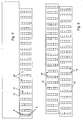
- FIG. 1 shows a detection system 1 for detecting bottles 2 or the like containers.
- the exemplary bottles 2 may have features arranged on their container wall, such as, for example, bottle seams and / or design features, so-called embossings.
- the detection system 1 has a lighting unit 3 and an optical arrangement 4 with at least one camera 5.
- the illumination unit 3 has a multiplicity of light sources 6 (FIG. FIG. 2 ), and is designed so that of the respective light source 6, a strip-shaped light beam 7 is projected onto a container wall portion 8, wherein the respective strip-shaped, on the container wall portion 8 projected light beams 7 are spaced from each other.
- the containers or bottles 2 may consist of a transparent, translucent or opaque material, and have a shiny surface.
- the bottle 2 may each have different colors and be filled with different filling media.
- the illumination unit 3 a support member 9 with an oriented to the container 2 light surface 10 and a rear side 11 opposite thereto.
- the support member 9 is exemplified as a circular cutout sheet metal strip.
- other suitable materials for the design of the carrier element 9 can be used.
- the conductor track 12 is designed as a flexible conductor track and has vertically arranged receiving strips 13, which are seen in a longitudinal direction of the conductor track 12 spaced from each other. At the receiving strip 13, the light sources 6 can be arranged. With its rear side, the conductor track 12 can be connected to the light surface of the carrier element 9.
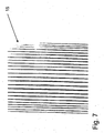
- a strip-shaped light pattern 15 is projected onto the container wall area 8.
- FIG. 7 An exemplary strip-shaped light pattern 15, which is projected onto a preferably cylindrical container wall region 8, is shown in FIG. 7 shown in inverse representation. This means that the light beams 7, and the strip-shaped light pattern 15 is shown in inverse representation black or dark, wherein the unilluminated container wall appears white or bright in inverse representation.
- the carrier element 9 On the carrier element 9 but also a plurality of conductor tracks 12 can be arranged, as exemplified in FIG. 3 shown.
- the conductor tracks 12 are arranged laterally offset from one another with their vertically arranged rows 14.
- the container 2 according to the embodiment according to FIG. 1 is transported past the detection system 1 in a labeling star of a labeling machine. Therefore, the carrier element 9 is advantageously designed so that it does not engage in the transport path (circular path) of the container 2. With the illumination unit 3, a strip-shaped light pattern 15 can thus be projected onto a container wall region 8, which corresponds to approximately 40% of the total circumference of the container 2.
- the optical arrangement 4 (FIG. FIG. 1 ) has three cameras 5 as exemplified.
- the cameras 5 are arranged vertically offset relative to the illumination unit 3. This means that the optical arrangement 4 can be arranged above or below the illumination unit 3.
- the optical arrangement 4 is arranged such that the container wall region 8 illuminated by the strip-shaped light pattern 15 can be accommodated.
- the optical arrangement 4, that is to say each camera 5, is connected to an evaluation and control unit 16, in which the images or image data supplied by the respective camera 5 are evaluated.
- the processing of the images or image data supplied by the camera 5 takes place, for example, by comparison with setpoint data stored in the evaluation and control unit 16.
- the evaluation and control unit 16 may also be referred to as image processing and control unit 16.
- the evaluation and control unit 16 is for example a computer or a computer-aided unit with corresponding inputs for analog or digital data supplied by the respective camera. Next, the evaluation and control unit 16 outputs not shown, which are connected to the individual components (eg container orientation, labeling) of the labeling machine.
- Each camera 5 is assigned an optical lens 17 by way of example.
- the respective optical lens 17 designed as a cylindrical lens, which is arranged with their end faces 18 perpendicular to the optics of the respective camera 5.
- the optical lens 17 can also be designed as a Fresnel lens, to name just another example.
- a targeted vertical stripe pattern 15 is thus projected onto the container body or onto the container wall region 8.
- the advantageous arrangement of the light sources 6 generates in the "total reflection" an image of the entire illumination unit
- the arrangement of these rows 14 thus reflects the surface of the container to be detected or the container wall portion 8.
- the rows 14 and the lines of the vertical stripe pattern are 15 (FIG. FIG. 7 ) regardless of container rotations or container positions in their number always aligned the same. If the bottle seam now invades this line structure (strip-shaped light pattern 15), the number and arrangement of the rows 14 will change. For example, a change in line mapping occurs.
- an absolutely exact position of the container seam or the bottle seam can be determined so advantageous regardless of container contents and container color.
- two detection systems 1 can be provided consecutively, so that an exact position determination of the container seam is ensured by rotation of the container by, for example, 90 °, this also, as the detection system 1, in particular with its carrier element 9 as described above in a labeling star not in this intervention should.
- second detection system by rotating the container 2, a further container wall region 8 can be inspected.
- the invention is based on the fact that the container rests on a rotatable turntable, and can be rotated in the feeding to the detection system 1.
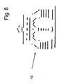
- the detection system 1 can also be used for recognizing external design features, so-called embossings 19, since the illumination unit 3 is formed from a plurality of individually selectively arranged light sources 6.
- FIG. 8 is an inverse representation of the image taken by the cameras 5.
- an optical lens in front of the respective cameras 5 can be dispensed with, wherein the illumination unit 2 can be used as a dark field illumination.
- a strip-shaped light pattern 15 is projected onto the container.
- the embossing 19 also creates a change on the container surface, like the bottle seam.
- the "Total Reflexion" ( Figure) reflects the structure and shape of Embossing 19 again.
- the detection system 1 is able to determine an absolutely exact position of the embossing 19, regardless of content and container color.
- a smooth surface that is a surface without embossing
- no highlights of the stripe pattern 15 projected onto the container arise.
- the surface appears black or dark (inversely white or bright) for the (optical) detection system 1.
- these highlights are produced by the optical arrangement or cameras as (white or light) points of light (inversely black or dark points of light) ).
- the smooth container surface appears black or dark (inversely white or bright), so that the entire embossing 19 can be seen from the optical arrangement 4 by means of the highlights.
- the lighting unit 3 is formed of a plurality of optical fibers 20, each having on its rear side 21 and support side 21, a light source 6.
- the rear side 21 is arranged opposite the light surface 10 of the illumination unit 3.
- an optical fiber 20 is shown in detail. Contrary to in FIG. 5 illustrated arrangement of the respective light source 6 to the respective light guide 20, the light source 6 preferably has a low, more preferably no distance to the back 21. On the rear side, the light emitted from the light source 6 is coupled into the light guide 20, and exits the light guide 20 from the light guide side. This is shown by means of the exemplary beam path 22.
- the respective light guide 20 is preferably designed as a colorless (crystal clear) Plexiglas rod in the form of a square bar. With each adjacent side surfaces 23, the light guides 20 are without gap to each other.
- the light guides 20 are held between two, not shown, vertically spaced end plates.
- the respective light surface 10 of the respective light guide 20 is processed so that the entire light surface 10, as the light surface 10 formed from the individual light guides 20 has a respectively adapted radius 24, so that an illumination unit 3 designed with a circular-section-like light surface 10 is formed.
- the individual light guides 20 are arranged side by side in the desired number between the end plates, in which case the entire light surface 10 is made with the desired radius 24.
- the radius 24 may be designed so that the lighting unit 3 does not engage in the raceway (labeling star).
- a homogeneously illuminated light surface 10 is formed.
- a mask is not shown, but may have vertically extending slots in predetermined widths and distances.
- the mask may be formed from a panel, which is adapted to the radius 24.
- each lighting unit 3 may have on their light surface 10 each have a different mask.
- the individual in FIG. 6 Small squares 25 each represent a light guide 20.
- a multiplicity of light guides 20 can be arranged one above the other and next to one another.
Landscapes
- Immunology (AREA)
- Pathology (AREA)
- Life Sciences & Earth Sciences (AREA)
- Chemical & Material Sciences (AREA)
- Analytical Chemistry (AREA)
- Biochemistry (AREA)
- Health & Medical Sciences (AREA)
- General Health & Medical Sciences (AREA)
- Physics & Mathematics (AREA)
- General Physics & Mathematics (AREA)
- Investigating Materials By The Use Of Optical Means Adapted For Particular Applications (AREA)
- Length Measuring Devices By Optical Means (AREA)
- Labeling Devices (AREA)
- Image Input (AREA)
- Details Of Rigid Or Semi-Rigid Containers (AREA)
- Containers Having Bodies Formed In One Piece (AREA)
Description
- Die Erfindung betrifft ein Erfassungssystem zum Erfassen von Flaschen oder dergleichen Behältern, gemäß dem Oberbegriff des Anspruchs 1 und wie aus der
EP 1 628 241 A1 bekannt. - Derartige Behälter können in der Art von Flaschen oder dergleichen für Flüssigkeiten, beispielsweise für Getränke verwendet werden. Die Behälter können aus einem transparenten, transluzenten oder opaken Material, beispielsweise aus Glas oder aus einem transluzenten Kunststoff, z.B. PET bestehen, und weisen eine glänzende Oberfläche auf. In den Behältern können Füllmedien unterschiedlichster Art eingefüllt sein, wobei die Behälter unterschiedliche Farben aufweisen können. Die Behälter werden zum Beispiel einer Etikettiermaschine zugeführt, in welcher ein Etikett in einer vorbestimmten und wiederholbaren Position stets gleich orientiert zu äußeren Positions- oder Gestaltungsmerkmalen bzw. Embossings auf der Außenseite des Behälters angeordnet werden soll. Das Etikett soll aber nicht nur korrekt zu Embossings oder anderen Merkmalen ausgerichtet sein, sondern möglichst auch faltenfrei bzw. ohne Erhebungen und/oder Vertiefungen auf dem Behälter angeordnet werden. Behälter können aber zwei vertikal verlaufende, einander direkt gegenüber angeordnete Flaschennähte oder auch nur eine Flaschennaht aufweisen. Insofern ist es durchaus gewünscht, dass das Etikett nicht auf eine der Flaschennähte bzw. auf der Flaschennaht bzw. Behälternaht aufgebracht wird, da dies die Optik des Etiketts bzw. des Behälters dahingehend stört, als das Etikett im Bereich der Ftaschennaht eine Falte (Erhebung/Vertiefung) aufweisen kann, so dass der Eindruck entsteht, das Etikett sei mit mangelnder Qualität auf den Behälter aufgebracht. Dies kann bei Endverbrauchern zu einem Meiden des Produkts führen.
- Der Erfindung liegt daher die Aufgabe zugrunde, ein Erfassungssystem der Eingangs genannten Art anzugeben, welches mit einfachen Mitteln Merkmale auf dem Behälter erkennt, so dass das Etikett nicht auf eine Flaschennaht aufgebracht und/oder korrekt ausgerichtet zu Embossings auf dem Behälter angeordnet werden kann.
- Erfindungsgemäß wird die Aufgabe durch ein Erfassungssystem mit den Merkmalen des Anspruchs 1 gelöst.
- Die Beleuchtungseinheit ist so ausgeführt, dass vertikal ausgerichtete Lichtstrahlen auf den Behälterwandbereich projiziert werden.
- In einer erfindungsgemäßen Ausgestaltung der Beleuchtungseinheit ist vorgesehen, dass diese ein Trägerelement mit einer zum Behälter orientierten Lichtfläche aufweist. An der Lichtfläche ist zumindest eine Leiterbahn angeordnet, an welcher zueinander beabstandet die Lichtquellen vertikal orientiert angeordnet sind. Die Leiterbahn ist bevorzugt flexibel, also biegbar ausgeführt und weist vertikal angeordnete Aufnahmestreifen für die Lichtquellen auf, so dass ein streifenförmiges Muster auf den Behälterwandbereich projiziert wird. Die Lichtquellen können beispielhaft als LED-Lichtquellen ausgeführt sein. Natürlich können die Lichtquellen auch als Infrarotlichtquelle ausgeführt sein. Bevorzugter weise sind die Lichtquellen gepulst, wobei die optische Anordnung bzw. die zumindest eine Kamera-mit der Lichtquelle synchronisiert wird.
- Das Trägerelement bzw. die Lichtfläche ist in der Art eines Kreisausschnitts ausgeführt, welche den zu inspizierenden bzw. den zu erfassenden Behälter zumindest bereichsweise umfasst, aber axial zu diesem beabstandet ist. An der Lichtfläche kann in einer ersten Ausgestaltung eine einzige Leiterbahn mit daran angeordneten Lichtquellen angeordnet sein. Denkbar ist aber auch, mehrere Leiterbahnen, vorzugsweise zwei Leiterbahnen mit daran angeordneten Lichtquellen an der Lichtfläche anzuordnen, wobei die Leiterbahnen zweckmäßiger Weise übereinander angeordnet sind, und wobei die einzelnen Lichtquellenreihen bzw. -streifen vorteilhaft einen seitlichen Versatz zueinander aufweisen können.
- Die optische Anordnung weist mehrere, bevorzugt drei Kameras auf, welche günstiger Weise korrelierend zu dem auf den Behälterwandbereich projizierten Streifenmuster so angeordnet sind, dass der gesamte von den Lichtquellen bestrahlte Behältervvandbereich aufnehmbar ist. In günstiger Ausführung ist zumindest ein Bereich von etwa 40% des Gesamtumfangs des Behälters von der optischen Anordnung aufnehmbar. Natürlich ist die optische Anordnung bezogen auf die Beleuchtungseinheit zweckmäßig höhenversetzt angeordnet.
- Dass Erfassungssystem ist bevorzugt einer Etikettiermaschine zugeordnet, welche einen Etikettierstern aufweist. Insofern sind das Trägerelement und auch die optische Anordnung bei der Ausführung mit dem Etikettierstern von den baulichen Gegebenheiten des Etikettiersternes abhängig ausführbar. Dies bedeutet, dass nur ein bestimmter Behälterwandbereich von der Beleuchtungseinheit bestrahlt und von der optischen Anordnung aufnehmbar ist. Von daher ist es zweckmäßig im Sinne der Erfindung, wenn das Trägerelement beispielhaft als gebogener Blechstreifen so ausgeführt ist, dass dieser nicht in die kreisförmige Laufbahn des Behälters bzw. des Etikettiersternes eingreift. Natürlich kann das Trägerelement auch aus anderen geeigneten Materialien ausgeführt sein. An dem Trägerelement kann die Leiterbahn bzw. können die Leiterbahnen in geeigneter Weise ortsstabil befestigt, beispielsweise mit ihrer Rückseite verklebt werden, um nur eine beispielhafte Befestigungsart zu nennen.
- In weiter günstiger Ausgestaltung kann vorgesehen sein, der zumindest einen Kamera, bevorzugt allen Kameras eine optische Linse, vorzugsweise in der Ausgestaltung als Zylinderlinse vorzulagern, um das auf den Behälterwandbereich projizierte Streifenmuster bzw. die vertikale Linienstruktur über den gesamten vertikalen Erfassungsbereich optisch zu spreizen. Die optische Linse kann auch als Fresnel-Linse ausgeführt sein, um nur ein weiteres geeignetes Beispiel für eine optische Linse zu nennen.
- Mittels der vorteilhaft vorgesehenen optischen Linse kann eine höhere optische Auflösung des Erfassungssystems erreicht werden, da sich die Linienstruktur wesentlich feiner über den gesamten Erfassungsbereich des optischen Erfassungssystems ausbreitet. Dies gilt natürlich auch für den Fall des Versatzes der beiden Leiterbahnen bzw. der darauf angeordneten Lichtquellenreihen bzw. streifen.
- Aufgrund der speziellen Anordnung der einzelnen Lichtquellen (Streifen bzw. Reihen) wird so ein gezieltes vertikales Streifenmuster auf den Behälterkörper bzw. auf den Behälterwandbereich projiziert. Die vorteilhafte Anordnung der Lichtquellen erzeugt in der "Total Reflexion" ein Abbild der gesamten Beleuchtungseinheit bzw. derer Lichtquellen in Streifen bzw. vertikal angeordneten Linien. Die Anordnung dieser Linien spiegelt somit die Oberfläche des zu erfassenden Behälters bzw. des Behälterwandbereiches. Sind an der Behälterwand bzw. an dem zu erfassenden Behälterwandbereich keine Veränderungen, wie zum Beispiel eine Flaschennaht angeordnet, sind die Linien unabhängig von Behälterrotationen oder Behälterpositionen in ihrer Anzahl zueinander immer gleich ausgerichtet. Fällt nun die Flaschennaht in diese Linienstruktur, ändert sich deren Anzahl und Anordnung zueinander. Es entsteht zum Beispiel eine Änderung der Linienabbildung. Mit der Erfindung kann so vorteilhaft unabhängig von Behälterinhalt und Behälterfarbe eine absolut exakte Position der Behälternaht bestimmt werden. Günstiger Weise können zwei Erfassungssysteme aufeinander folgend vorgesehen werden, so dass durch Rotation des Behälters um beispielsweise 90° eine exakte Positionsbestimmung der Behälternaht sichergestellt ist, dies auch deshalb, als das Erfassungssystem, insbesondere mit seinem Trägerelement wie zuvor beschrieben bei einem Etikettierstern nicht in diesen Eingreifen soll. Mit dem folgenden, zweiten Erfassungssystem kann durch ein Verdrehen des Behälters ein weiterer Behälterwandbereich inspiziert werden. Hierbei liegt der Erfindung die Tatsache zugrunde, dass der Behälter auf einem verdrehbaren Drehteller aufsteht, und bei dem Zuführen zu dem Erfassungssystem verdreht werden kann.
- Um zu vermeiden, dass durch die Umgebung einfallende Reflexionen des Behälters eine Erkennungsgenauigkeit negativ beeinflusst, können die Lichtquellen als Infrarotlichtquelle ausgeführt sein, wobei auch ein Tageslichtsperrflter vorgesehen werden kann.
- Mittels dem Erfassen bzw. der Positionsbestimmung der Behälternaht im Auflichtverfahren ist eine Ausrichtung des Behälters möglich, so dass ein Etikett an Stellen angebracht werden kann, an denen sich keine Behälternaht befindet, wodurch zum Beispiel Etikettenerhebungen (Falten) vermieden werden.
- Das vorteilhaft ausgeführte Erfassungssystem kann im Sinne der Erfindung aber nicht nur zur Lagebestimmung der Behälternaht eingesetzt werden. Da die Beleuchtungseinheit aus einer Vielzahl von einzeln gezielten Lichtquellen gebildet ist, kann diese günstiger Weise auch zur Erkennung von äußeren Gestaltungsmerkmalen, so genannten Embossings eingesetzt werden. Auf eine optische Linse vor den jeweiligen Kameras kann dabei verzichtet werden, wobei die Beleuchtungseinheit als Dunkelfeld-Beleuchtung einsetzbar ist. Wie zuvor wird dabei ein streifenförmiges Lichtmuster auf den Behälter projiziert. Das Embossing erzeugt ebenfalls wie die Flaschennaht eine Veränderung auf der Behälteroberfläche. Über die "Total Reflexion" (Abbildung) wird die Struktur und die Form des Embossings wieder gespiegelt. Diese Strukturen können je nach Drehposition des Behälters für das (optische) Erfassungssystem eingelernt werden. Vorteilhaft ist das Erfassungssystem so in der Lage, unabhängig von Inhalt und Behälterfarbe eine absolut exakte Position des Embossings zu bestimmen. Bei einer glatten Oberfläche, also eine Oberfläche ohne Embossing, entstehen keine Glanzpunkte des auf den Behälter projizierten Streifenmusters. Die Oberfläche erscheint für das (optische) Erfassungssystem schwarz. Fällt das auf den Behälter projizierte Streifenmuster dagegen auf das Embossing, bzw. auf die Erhebungen, entstehen diese Glanzpunkte, welche von der optischen Anordnung bzw. von den Kameras als (weiße) Lichtpunkte aufgenommen werden. Zwischen den Glanzpunkten erscheint die glatte Behälteroberfläche schwarz, so dass das gesamte Embossing mittels der Glanzpunkte von der Kameraanordnung erkennbar ist. Mittels der Erkennung des Embossings ist eine Ausrichtung zum Korrekten, also ausgerichteten Aufbringen des Etikettes in Relation zu dem Embossing möglich.
- In weiter günstiger Ausgestaltung ist das Trägerelement der Beleuchtungseinheit als Abschlussplatte ausgeführt, wobei zwei zueinander vertikal beabstandete Abschlussplatten vorgesehen sind. Zwischen den einander vertikal beabstandeten Abschlussplatten sind Lichtleiter in der bevorzugten Ausgestaltung als farblose (glasklare) Plexiglasstäbe angeordnet. Günstiger Weise sind eine Vielzahl von Lichtleitern direkt nebeneinander liegend vorgesehen. Den Lichtleitern ist an ihrer Tragseite gegenüberliegend zur Lichtfläche jeweils eine Lichtquelle zugeordnet, welche möglichst nah, bevorzugt ohne Abstand an der Tragseite angeordnet ist. Dies hat den Vorteil, dass die Lichtquellen bezogen auf eine Anordnung auf einer Leiterbahn flexibler angeordnet werden können; Denn auf der Leiterplatte ist deren Position durch die fixe Anordnung der Aufnahmestreifen statisch vorgegeben. Im Gegensatz dazu weisen die Lichtleiter eine plane Rückseite bzw. Tragseite und eine dazu gegenüberliegende Lichtfläche auf, welche in einem frei wählbaren Radius abgearbeitet, beispielsweise abgefräst werden kann, so dass lichtflächenseitig wiederum eine kreisausschnittsartige Beleuchtungseinheit gebildet ist. Selbstverständlich können die an der Lichtfläche angeordneten Stirnseiten der Abschlussplatten entsprechend mit bearbeitet werden. Dies hat den Vorteil, dass der Lichtgeber, also die aneinander gereihten Lichtleiter nicht mehr gekrümmt sein muss, sondern entsprechend bearbeitet werden kann. Die gekrümmte Lichtfläche ist so homogen beleuchtet.
- Um ein Streifenmuster auf die Behälteroberfläche zu projizieren, ist daher vorteilhaft vorgesehen, die Lichtfläche mit einer Maske zu versehen, welche vertikale Lichtaustrittsöffnungen, also vertikale Lichtstreifen (Schlitze) aufweist. Natürlich können unterschiedliche Masken mit unterschiedlichen Schlitz- bzw. Lichtmustern auf der Lichtfläche angeordnet werden. Mittels der jeweiligen Maske kann so ein beliebiges Muster auf den Behälter bzw. auf den Behälterwandbereich projiziert werden. Die Maske kann in zweckmäßiger Ausführung als ein an die Krümmung der Lichtfläche angepasstes Blendelement in der bevorzugten Ausführung als Blendblech mit Schlitzen in vorgebbaren Breiten und vorgebbaren Abständen ausgeführt sein. Natürlich kann die Maske aber auch ein flexibles Element sein, in welchem die Schlitze eingebracht sind, um die Maske unabhängig von dem Radius der Lichtfläche einsetzen zu können. Die Maske kann abhängig von dem Behälterdurchmesser, und/oder der Auflösung der Kamera ausgeführt sein. Möglich ist natürlich die Lichtleiter so zu dimensionieren, dass mehrere Masken auf der Lichtfläche übereinander liegend angeordnet werden können, wobei die jeweiligen Schlitze der übereinander angeordneten Masken dann zumindest einen seitlichen Versatz zueinander aufweisen können. Denkbar ist aber auch die Beleuchtungseinheit kaskadiert auszuführen, also mehrere Beleuchtungseinheiten übereinander angeordnet vorzusehen, wobei jede Beleuchtungseinheit an ihrer Lichtfläche eine jeweils andere Maske aufweisen könnte. Möglich ist auch, mehrere Lichtleiter übereinander und nebeneinander angeordnet zwischen den Abschlussplatten vorzusehen.
- Auch mit dieser vorteilhaften Weiterbildung der Beleuchtungseinheit werden einzelne Lichtquellen, also der jeweils aus den Schlitzen der Maske austretende Lichtstreifen als "Total Reflexion" bzw. Abbildung auf den Behälter projizierbar, wobei allerdings der Aufwand zur Herstellung der Leiterbahnen entfallen könnte. Durch die jeweils individuell herstellbare Maske wird zudem eine größere Flexibilität erreicht. Vorteilhaft wurde gefunden, dass die so hergestellte Beleuchtungseinheit bei einem Verzicht auf die Maske an ihrer Lichtfläche auch als Auflicht-Hellfeldbeleuchtung eingesetzt werden kann.
- In einer vorteilhaften Ausgestaltung können die Lichtleiter als Vierkantstäbe ausgeführt sein, deren Seitenflächen jeweils plan ausgeführt sind, wobei die jeweils benachbarten Lichtleiter ohne Abstand mit ihren Seitenflächen aneinander liegend angeordnet sind.
- Weitere vorteilhafte Ausgestaltungen der Erfindung sind in den Unteransprüchen und der folgenden Figurenbeschreibung offenbart. Es zeigen
- Fig.1
- einen prinzipiellen Aufbau eines Erfassungssystems,
- Fig. 2
- eine Leiterbahn als Einzelheit,
- Fig. 3
- zwei übereinander angeordnete Leiterbahnen mit Versatz der Lichtstreifen,
- Fig. 4
- eine Beleuchtungseinheit in vorteilhafter Weiterbildung in einer Aufsicht,
- Fig. 5
- eine Lichteinkopplung in einen Lichtleiter der Beleuchtungseinheit nach
Figur 4 , - Fig. 6
- einen kaskadierten Aufbau mehrere Beleuchtungseinheiten gemäß
Figur 4 , - Fig. 7
- eine inverse Darstellung eines Lichtmusters auf einer Behälterwand, und
- Fig. 8
- eine inverse Darstellung eines Embossings.
- In den unterschiedlichen Figuren sind gleiche Teile stets mit denselben Bezugszeichen versehen, weswegen diese in der Regel auch nur einmal beschrieben werden.
-
Figur 1 zeigt ein Erfassungssystem 1 zum Erfassen von Flaschen 2 oder dergleichen Behältern. Die beispielhaften Flaschen 2 können an ihrer Behälterwand angeordnete Merkmale wie zum Beispiel Flaschennähte und/oder Gestaltungsmerkmale, so genannte Embossings aufweisen. Das Erfassungssystem 1 weist eine Beleuchtungseinheit 3 und eine optische Anordnung 4 mit zumindest einer Kamera 5 auf. - Die Beleuchtungseinheit 3 weist eine Vielzahl von Lichtquellen 6 (
Figur 2 ) auf, und ist so ausgeführt, dass von der jeweiligen Lichtquelle 6 ein streifenförmiger Lichtstrahl 7 auf einen Behälterwandbereich 8 projiziert wird, wobei die jeweils streifenförmigen, auf den Behälterwandbereich 8 projizierten Lichtstrahlen 7 zueinander beabstandet sind. - Die Behälter bzw. Flaschen 2 können aus einem transparenten, transluzenten oder opaken Material bestehen, und weisen eine glänzende Oberfläche auf. Die Flasche 2 kann jeweils unterschiedliche Farben aufweisen und mit jeweils unterschiedlichen Füllmedien gefüllt sein.
- Bei dem in
Figur 1 dargestellten Ausführungsbeispiel weist die Beleuchtungseinheit 3 ein Trägerelement 9 mit einer zum Behälter 2 orientierten Lichtfläche 10 und einer dazu gegenüberliegenden Rückseite 11 auf. Das Trägerelement 9 ist beispielhaft als kreisausschnittartiger Blechstreifen ausgeführt. Natürlich können auch andere geeignete Materialien zur Ausgestaltung des Trägerelementes 9 eingesetzt werden. - An der Lichtfläche 10 ist zumindest eine Leiterbahn 12 (
Figur 2 ) angeordnet. Die Leiterbahn 12 ist als flexible Leiterbahn ausgeführt und weist vertikal angeordnete Aufnahmestreifen 13 auf, die in einer Längsrichtung der Leiterbahn 12 gesehen zueinander beabstandet sind. An den Aufnahmestreifen 13 können die Lichtquellen 6 angeordnet werden. Mit ihrer Rückseite ist die Leiterbahn 12 mit der Lichtfläche des Trägerelementes 9 verbindbar. - Mit der Leiterbahn 12, bzw. mit den darauf in vertikalen Reihen 14 bzw. Linien angeordneten Lichtquellen 6 wird ein streifenförmiges Lichtmuster 15 auf den Behälterwandbereich 8 projiziert.
- Ein beispielhaft streifenförmiges Lichtmuster 15, welches auf einen bevorzugt zylindrisch ausgeführten Behälterwandbereich 8 projiziert wird, ist in
Figur 7 in inverser Darstellung gezeigt. Dies bedeutet, dass die Lichtstrahlen 7, bzw. das streifenförmige Lichtmuster 15 in inverser Darstellung schwarz bzw. dunkel dargestellt ist, wobei die nicht angestrahlte Behälterwand in inverser Darstellung weiß bzw. hell erscheint. - An dem Trägerelement 9 können aber auch mehrere Leiterbahnen 12 angeordnet werden, wie beispielhaft in
Figur 3 gezeigt. Hierbei sind die Leiterbahnen 12 mit ihren vertikal angeordneten Reihen 14 seitlich versetzt zueinander angeordnet. - Der Behälter 2 nach dem Ausführungsbeispiel gemäß
Figur 1 wird in einem Etikettierstern einer Etikettiermaschine an den Erfassungssystem 1 vorbeitransportiert. Von daher ist das Trägerelement 9 vorteilhaft so ausgeführt, dass dieses nicht in den Transportweg (Kreisbahn) des Behälters 2 eingreift. Mit der Beleuchtungseinheit 3 kann so ein streifenförmiges Lichtmuster 15 auf einen Behälterwandbereich 8 projiziert werden, der etwa 40% des Gesamtumfangs des Behälters 2 entspricht. - Die optische Anordnung 4 (
Figur 1 ) weist wie beispielhaft dargestellt drei Kameras 5 auf. Die Kameras 5 sind bezogen auf die Beleuchtungseinheit 3 höhenversetzt angeordnet. Dies bedeutet, dass die optische Anordnung 4 oberhalb oder unterhalb der Beleuchtungseinheit 3 angeordnet sein kann. Die optische Anordnung 4 ist so angeordnet, dass der mit dem streifenförmigen Lichtmuster 15 ausgeleuchtete Behälterwandbereich 8 aufnehmbar ist. Die optische Anordnung 4, also jede Kamera 5 ist mit einer Auswerte- und Steuereinheit 16 verbunden, in welcher die von der jeweiligen Kamera 5 gelieferten Bilder oder Bilddaten ausgewertet werden. Die Verarbeitung der von der Kamera 5 gelieferten Bilder oder Bilddaten erfolgt beispielsweise durch Vergleich mit in der Auswerte- und Steuereinheit 16 abgespeicherten Solldaten. Insofern kann die Auswerte- und Steuereinheit 16 auch als Bildverarbeitungs- und Steuereinheit 16 bezeichnet werden. Die Auswerte-und Steuereinheit 16 ist beispielsweise ein Rechner oder eine rechnergestützte Einheit mit entsprechenden Eingängen für analoge oder digitale von der jeweiligen Kamera gelieferten Daten. Weiter weist die Auswerte- und Steuereinheit 16 nicht dargestellte Ausgänge auf, welche mit den einzelnen Komponenten (z.B. Behälterausrichtung, Etikettieraggregat) der Etikettiermaschine verbunden sind. - Jeder Kamera 5 ist beispielhaft eine optische Linse 17 zugeordnet. In dem dargestellten Ausführungsbeispiel nach
Figur 1 ist die jeweilige optische Linse 17 als Zylinderlinse ausgeführt, welche mit ihren Stirnflächen 18 senkrecht zur Optik der jeweiligen Kamera 5 angeordnet ist. Die optische Linse 17 kann auch als Fresnel-Linse ausgeführt sein, um nur ein weiteres Beispiel zu nennen. - Aufgrund der speziellen Anordnung der einzelnen Lichtquellen 6 (Streifen bzw. Reihen 14) wird so ein gezieltes vertikales Streifenmuster 15 auf den Behälterkörper bzw. auf den Behälterwandbereich 8 projiziert. Die vorteilhafte Anordnung der Lichtquellen 6 erzeugt in der "Total Reflexion" ein Abbild der gesamten Beleuchtungseinheit 3 bzw. derer Lichtquellen 6 in Streifen bzw. vertikal angeordneten Reihen 14. Die Anordnung dieser Reihen 14 spiegelt somit die Oberfläche des zu erfassenden Behälters bzw. des Behälterwandbereiches 8. Sind an der Behälterwand bzw. an dem zu erfassenden Behälterwandbereich 8 keine Veränderungen, wie zum Beispiel eine Flaschennaht angeordnet, sind die Reihen 14 bzw. die Linien des vertikalen Streifenmusters 15 (
Figur 7 ) unabhängig von Behälterrotationen oder Behälterpositionen in ihrer Anzahl zueinander immer gleich ausgerichtet. Würde nun die Flaschennaht in diese Linienstruktur (streifenförmiges Lichtmuster 15) einfallen, ändert sich Anzahl und Anordnung der Reihen 14 zueinander. Es entsteht zum Beispiel eine Änderung der Linienabbildung. Mit der Erfindung kann so vorteilhaft unabhängig von Behälterinhalt und Behälterfarbe eine absolut exakte Position der Behälternaht bzw. der Flaschennaht bestimmt werden. - Günstiger Weise können zwei Erfassungssysteme 1 aufeinander folgend vorgesehen werden, so dass durch Rotation des Behälters um beispielsweise 90° eine exakte Positionsbestimmung der Behälternaht sichergestellt ist, dies auch deshalb, als das Erfassungssystem 1, insbesondere mit seinem Trägerelement 9 wie zuvor beschrieben bei einem Etikettierstern nicht in diesen Eingreifen soll. Mit dem folgenden, zweiten Erfassungssystem kann durch ein Verdrehen des Behälters 2 ein weiterer Behälterwandbereich 8 inspiziert werden. Hierbei liegt der Erfindung die Tatsache zugrunde, dass der Behälter auf einem verdrehbaren Drehteller aufsteht, und bei dem Zuführen zu dem Erfassungssystem 1 verdreht werden kann.
- Wie
Figur 8 entnehmbar ist, kann das Erfassungssystem 1 auch zum Erkenn von äußeren Gestaltungsmerkmalen, so genannten Embössings 19 eingesetzt werden, da die Beleuchtungseinheit 3 aus einer Vielzahl von einzeln gezielt angeordneten Lichtquellen 6 gebildet ist. AuchFigur 8 ist eine inverse Darstellung des von den Kameras 5 aufgenommenen Bildes. Auf eine optische Linse vor den jeweiligen Kameras 5 kann dabei verzichtet werden, wobei die Beleuchtungseinheit 2 als Dunkelfeld-Beleuchtung einsetzbar ist. Wie zuvor wird dabei ein streifenförmiges Lichtmuster 15 auf den Behälter projiziert. Das Embossing 19 erzeugt ebenfalls wie die Flaschennaht eine Veränderung auf der Behälteroberfläche. Über die "Total Reflexion" (Abbildung) wird die Struktur und die Form des Embossings 19 wieder gespiegelt. Diese Strukturen können je nach Drehposition des Behälters 2 für das (optische) Erfassungssystem 1 eingelernt werden. Vorteilhaft ist das Erfassungssystem 1 so in der Lage, unabhängig von Inhalt und Behälterfarbe eine absolut exakte Position des Embossings 19 zu bestimmen. Bei einer glatten Oberfläche, also eine Oberfläche ohne Embossing, entstehen keine Glanzpunkte des auf den Behälter projizierten Streifenmusters 15. Die Oberfläche erscheint für das (optische) Erfassungssystem 1 schwarz bzw. dunkel (invers weiß bzw. hell). Fällt das auf den Behälter 2 projizierte Streifenmuster 15 dagegen auf das Embossing 19, bzw. auf die Erhebungen, entstehen diese Glanzpunkte, welche von der optischen Anordnung bzw. von den Kameras als (weiße bzw. helle) Lichtpunkte (invers schwarze bzw. dunkle Lichtpunkte) aufgenommen werden. Zwischen den Glanzpunkten erscheint die glatte Behälteroberfläche schwarz bzw. dunkel (invers weiß bzw. hell), so dass das gesamte Embossing 19 mittels der Glanzpunkte von der optischen Anordnung 4 erkennbar ist. Mittels der Erkennung des Embossings 19 ist eine Ausrichtung zum Korrekten, also ausgerichteten Aufbringen des Etikettes in Relation zu dem Embossing 19 möglich. - Bei dem in
Figur 4 dargestellten Ausführungsbeispiel ist die Beleuchtungseinheit 3 aus einer Vielzahl von Lichtleitern 20 gebildet, die jeweils an ihrer Rückseite 21 bzw. Tragseite 21 eine Lichtquelle 6 aufweisen. Die Rückseite 21 ist gegenüberliegend zur Lichtfläche 10 der Beleuchtungseinheit 3 angeordnet. - In
Figur 5 ist ein Lichtleiter 20 als Einzelheit gezeigt. Entgegen der inFigur 5 dargestellten Anordnung der jeweiligen Lichtquelle 6 zu dem jeweiligen Lichtleiter 20 weist die Lichtquelle 6 bevorzugt einen geringen, weiter bevorzugt gar keinen Abstand zur Rückseite 21 auf. Rückseitig wird das aus der Lichtquelle 6 emittierte Licht in den Lichtleiter 20 eingekoppelt, und tritt lichtflächenseitig aus dem Lichtleiter 20 aus. Dies ist mittels des beispielhaften Strahlenganges 22 gezeigt. - Der jeweilige Lichtleiter 20 ist bevorzugt als farbloser (glasklarer) Plexiglasstab in der Form eines Vierkantstabes ausgeführt. Mit jeweils benachbarten Seitenflächen 23 liegen die Lichtleiter 20 ohne Spalt aneinander.
- Die Lichtleiter 20 sind zwischen zwei nicht dargestellten, vertikal beabstandeten Abschlussplatten gehalten.
- Gemäß dem Ausführungsbeispiel nach
Figur 4 wird die jeweilige Lichtfläche 10 des jeweiligen Lichtleiters 20 so bearbeitet, dass die gesamte Lichtfläche 10, als die aus den einzelnen Lichtleitern 20 gebildete Lichtfläche 10 einen jeweils angepassten Radius 24 aufweist, so dass eine mit einer kreisausschnittsartigen Lichtfläche 10 ausgeführte Beleuchtungseinheit 3 gebildet ist. In bevorzugter Ausführung werden die einzelnen Lichtleiter 20 dabei in der gewünschten Anzahl nebeneinander angeordnet zwischen den Abschlussplatten gelegt, wobei dann die gesamte Lichtfläche 10 mit dem gewünschten Radius 24 hergestellt wird. Der Radius 24 kann so ausgeführt sein, dass die Beleuchtungseinheit 3 nicht in die Laufbahn (Etikettierstern) eingreift. - Durch diese vorteilhafte Ausführung wird eine homogen beleuchtete Lichtfläche 10 gebildet. Um das streifenartige Lichtmuster 15 auf den Behälterwandbereich 8 projizieren zu können, ist vorteilhaft vorgesehen, die homogen beleuchtete Lichtfläche 10 mit einer Maske abzudecken. Die Maske ist nicht dargestellt, kann aber vertikal verlaufende Schlitze in vorgebbaren Breiten und Abständen aufweisen. Die Maske kann aus einem Blendblech gebildet sein, welches an den Radius 24 angepasst ist.
- Wie der beispielhaften Skizze gemäß
Figur 6 entnehmbar ist, können mehrere Beleuchtungseiriheiten 3 kaskadiert vorgesehen werden, wobei jede Beleuchtungseinheit 3 an ihrer Lichtfläche 10 eine jeweils unterschiedliche Maske aufweisen kann. Die einzelnen inFigur 6 klein dargestellten Quadrate 25 stellen dabei jeweils einen Lichtleiter 20 dar. Wie beispielhaft dargestellt kann eine Vielzahl von Lichtleitern 20 übereinander und nebeneinander angeordnet sein. -
- 1
- Erfassungssystem
- 2
- Behälter/Flasche
- 3
- Beleuchtungseinheit
- 4
- Optische Anordnung
- 5
- Kamera
- 6
- Lichtquelle
- 7
- Lichtstrahlen
- 8
- Behälterwandbereich
- 9
- Trägerelement
- 10
- Lichtfläche
- 11
- Rückseite von 9
- 12
- Leiterbahn
- 13
- Aufnahmestreifen
- 14
- Vertikale Reihen bzw. Linien
- 15
- Vertikales Lichtmuster
- 16
- Auswerte- und Steuereinheit
- 17
- Optische Linse
- 18
- Stirnflächen von 17
- 19
- Embossing
- 20
- Lichtleiter
- 21
- Rückseite von 20
- 22
- Strahlengang
- 23
- Seitenflächen von 20
- 24
- Radius
- 25
- Quadrate
Claims (8)
- Erfassungssystem zum Erfassen von Flaschen (2) und dergleichen Behälter (2), welcher an einer Behälterwand angeordnete Merkmale aufweisen, wobei das Erfassungssystem (1), an welchem die Behälter (2) auf einem Drehteller aufstehend verdrehbar vorbeltransportiert werden, elBeleuchtungseinheit (3), die ein Trägerelement (9) mit einer zum Behälter (2) orientierten kreisausschnittsartigen Lichtfläche (10) aufweiset, welche den Behälter bereichsweise umfasst aber axial zu diesem beabstandet ist, und eine optische Anordnung (4) mit zumindest einer Kamera (5) aufweist, dadurch gekennzeichnet, dass die Beleuchtungseinheit (3) an ihrer Lichtfläche (10) zumindest eine Leiterbahn (12) aufweist, an welcher Lichtquellen (6) vertikal und in vertikal ausgerichteten Reihen (14) angeordnet sind, welche zu einander beabstandet sind, so dass von der Beleuchtungseinheit (3) ein streifenförmiges, vertikal ausgerichtetes Lichtmuster (15) mit mehreren, zueinander beabstandeten, vertikal ausgerichteten Lichtstrahlen- bzw. streifen (7) auf einen Behalterwandbereich (8) projizierbar Ist, wobei der mit dem streifenförmigen Lichtmuster (15) bestrahlte Behälterwandbereich (8) etwa 40% des Gesamtumfangs des Behälters (2) entspricht welcher Behälterwandbereich (8) von der optischen Anordnung (4) mit mehreren Kameras (5) aufnehmbar ist, wobei die Kameras (5) höhenversetzt zu der Beleuchtungseinheit (3) angeordnet sind.
- Erfassungssystem nach Anspruch 1, dadurch gekennzeichnet, dass der zumindest einen Kamera (5) eine optische Linse (17) zugeordnet ist.
- Erfassungssystem nach einem der vorhergehenden Ansprüche, dadurch gekennzeichnet, dass die Beleuchtungseinheit (3) aus einer Vielzahl von nebeneinander angeordneten Lichtleitem (20) gebildet ist, denen jeweils eine Lichtquelle (6) rückseitig zugeordnet, ist, wobei die Lichtfläche (10) in einem Radius (24) ausgeführt ist,
- Erfassungssystem nach einem der vorhergehenden Ansprüche 1,2 dadurch gekennzeichnet, dass die Beleuchtungseinheit (3) aus einer Vielzahl von nebeneinander angeordneten Lichtleitern (20) gebildet ist, denen jeweils eine Lichtquelle (6) rückseitig zugeordnet ist, wobei an der Lichtfläche (10) eine Maske mit vertikal ausgeführten Lichtaustrittsöffnungen angeordnet ist.
- Erfassungssystem nach Anspruch 4, dadurch gekennzeichnet, dass die Maske als Blendelement mit vorgebbaren Schlitzbreiten und Schlitzabständen ausgeführt ist.
- Erfassungssystem nach einem der Ansprüche 3 bis 5, dadurch gekennzeichnet, dass die Lichtleiter (20) als farblose, glasklare Plexiglasstäbe in der Ausgestaltung als Vierkantstäbe ausgeführt sind, die mit ihren jeweiligen benachbarten Seitenflächen (23) plan aneinander liegen.
- Verwendung eines Erfassungssystems (1) nach einem der vorhergehenden Ansprüche zum Erkennen von Behaiternahten und/oder Embossings.
- Verwendung eines Erfassungssystems (1) nach einem der vorhergehenden Ansprüche in einer Etikettiermaschine.
Applications Claiming Priority (2)
| Application Number | Priority Date | Filing Date | Title |
|---|---|---|---|
| DE102008053876A DE102008053876A1 (de) | 2008-10-30 | 2008-10-30 | Flaschennaht- und Embossingausrichtung |
| PCT/EP2009/007705 WO2010049137A1 (de) | 2008-10-30 | 2009-10-28 | Flaschennaht- und embossingausrichtung |
Publications (2)
| Publication Number | Publication Date |
|---|---|
| EP2342136A1 EP2342136A1 (de) | 2011-07-13 |
| EP2342136B1 true EP2342136B1 (de) | 2016-03-30 |
Family
ID=41647201
Family Applications (1)
| Application Number | Title | Priority Date | Filing Date |
|---|---|---|---|
| EP09751791.6A Active EP2342136B1 (de) | 2008-10-30 | 2009-10-28 | Flaschennaht- und embossingausrichtung |
Country Status (9)
| Country | Link |
|---|---|
| US (1) | US8767201B2 (de) |
| EP (1) | EP2342136B1 (de) |
| JP (1) | JP6172886B2 (de) |
| DE (1) | DE102008053876A1 (de) |
| HU (1) | HUE027500T2 (de) |
| PL (1) | PL2342136T3 (de) |
| PT (1) | PT2342136E (de) |
| RU (1) | RU2498931C2 (de) |
| WO (1) | WO2010049137A1 (de) |
Families Citing this family (14)
| Publication number | Priority date | Publication date | Assignee | Title |
|---|---|---|---|---|
| DE102008027814A1 (de) * | 2008-06-11 | 2009-12-17 | Khs Ag | Behälter, insbesondere Flasche mit einem Erkennungselement zum Ausrichten |
| DE102009020919A1 (de) | 2009-05-12 | 2010-11-18 | Krones Ag | Vorrichtung zum Erkennen von Erhebungen und/oder Vertiefungen auf Flaschen, insbesondere in einer Etikettiermaschine |
| DE102010032166B4 (de) | 2010-07-23 | 2016-03-10 | Khs Gmbh | Erfassungssystem und Inspektionsverfahren zur Flaschennaht- und Embossingausrichtung |
| DE102010047621A1 (de) | 2010-10-07 | 2012-04-12 | Krones Aktiengesellschaft | Vorrichtung und Verfahren zur Erkennung einer Drehstellung von Kunststoffvorformlingen |
| DE102011083377A1 (de) * | 2011-09-26 | 2013-03-28 | Krones Aktiengesellschaft | Vorrichtung und Verfahren zum Ausrichten von Behältern |
| DE102012009783B3 (de) * | 2012-05-18 | 2013-08-14 | Khs Gmbh | Verfahren und Vorrichtung zur Inspektion von Leerflaschen |
| DE102014102450A1 (de) | 2014-02-25 | 2015-08-27 | Khs Gmbh | Inspektionsvorrichtung mit inverser Folienlinse |
| DE102014102449A1 (de) † | 2014-02-25 | 2015-08-27 | Khs Gmbh | Inspektionsvorrichtung |
| WO2016155848A1 (en) * | 2015-03-30 | 2016-10-06 | P.E. Labellers S.P.A. | Device and method for automatically orienting containers entering a labeling machine |
| ITUA20162898A1 (it) * | 2016-04-26 | 2017-10-26 | Sacmi | Macchina etichettatrice di contenitori per liquidi con dispositivo di ispezione ottica |
| DE102020112191A1 (de) | 2020-05-06 | 2021-11-11 | Krones Aktiengesellschaft | Behälterbehandlungsmaschine und Verfahren zum Ausrichten eines Behälters in einer Behälteraufnahme einer Behälterbehandlungsmaschine |
| DE102022104990A1 (de) | 2022-03-03 | 2023-09-07 | Emhart Glass Sa | VORRICHTUNG UND VERFAHREN ZUM INSPIZIEREN VON GEFÄßEN |
| CN115598132B (zh) * | 2022-10-10 | 2024-06-07 | 东北大学 | 一种基于机器视觉的棒材计数及对齐检测的装置和方法 |
| KR102847354B1 (ko) * | 2023-09-19 | 2025-08-20 | 에너지움 주식회사 | 시험관 공급 모듈을 포함하는 시험관 공급 장치 및 이를 이용한 시험관 공급 방법 |
Family Cites Families (21)
| Publication number | Priority date | Publication date | Assignee | Title |
|---|---|---|---|---|
| US3814521A (en) * | 1972-09-12 | 1974-06-04 | Hoffmann La Roche | Object recognition |
| JPS60134196U (ja) * | 1984-02-16 | 1985-09-06 | 三菱重工業株式会社 | 核燃料集合体の検査装置 |
| JPH06100555B2 (ja) * | 1990-12-19 | 1994-12-12 | 東洋ガラス株式会社 | 透明物体の欠陥検査方法とその装置 |
| JPH0815163A (ja) * | 1994-07-04 | 1996-01-19 | Huebrain:Kk | 筒状物の外観検査装置 |
| JP3007849B2 (ja) * | 1996-06-21 | 2000-02-07 | 松下電工株式会社 | 物体表面の形状検出方法及び形状検出装置 |
| DE19741384A1 (de) * | 1997-09-19 | 1999-03-25 | Heuft Systemtechnik Gmbh | Verfahren zum Erkennen von diffus streuenden Materialien, Verunreinigungen und sonstigen Fehlern bei transparenten Gegenständen |
| US6031221A (en) * | 1998-02-19 | 2000-02-29 | Emhart Glass S.A. | Container inspection machine |
| JP2000121569A (ja) * | 1998-10-16 | 2000-04-28 | Showa Corp | ロッド表面傷検査装置 |
| DE29907762U1 (de) | 1999-04-27 | 1999-10-21 | Horst, Michael, Dipl.-Ing., 34128 Kassel | Vorrichtung zur Untersuchung eines Behälters auf Oberflächenfehler |
| DE19923264A1 (de) * | 1999-05-20 | 2001-01-18 | Patent Treuhand Ges Fuer Elektrische Gluehlampen Mbh | Beleuchtungsvorrichtung |
| MXPA04004677A (es) * | 2001-11-16 | 2004-09-10 | Heineken Tech Services | Metodo y aparato para generar una imagen de referencia robusta de un recipiente y para seleccion del recipiente. |
| JP3382613B1 (ja) * | 2002-04-09 | 2003-03-04 | シーシーエス株式会社 | 照明装置の製造方法 |
| JP2006525838A (ja) * | 2003-05-09 | 2006-11-16 | コーニンクレッカ フィリップス エレクトロニクス エヌ ヴィ | 半導体発光ダイオードを使用する日焼け装置 |
| JP2006047290A (ja) * | 2004-06-30 | 2006-02-16 | Omron Corp | 基板検査用の画像生成方法、基板検査装置、および基板検査用の照明装置 |
| DE102004040164A1 (de) * | 2004-08-19 | 2006-03-02 | Khs Maschinen- Und Anlagenbau Ag | Vorrichtung zur Erfassung von Strukturen, wie Profilierungen oder Prägungen an Körpern von Flaschen oder dergl. Behälter |
| DE102005017957A1 (de) * | 2005-04-18 | 2006-10-26 | Khs Ag | Inspektionsvorrichtung |
| DE102006008840B4 (de) * | 2006-02-25 | 2009-05-14 | Fraunhofer-Gesellschaft zur Förderung der angewandten Forschung e.V. | Beleuchtungsvorrichtung für zylindrische Objekte, damit durchgeführtes Oberflächenuntersuchungsverfahren und Computerprogrammprodukt |
| JP4829030B2 (ja) * | 2006-08-08 | 2011-11-30 | 株式会社サトー | ラベル貼付装置 |
| FR2907553B1 (fr) * | 2006-10-24 | 2009-02-13 | Tiama Sa | Procede et dispositif pour detecter des defauts a faible et fort contrastes dans des objets transparents ou translucides |
| JP4971043B2 (ja) * | 2007-06-13 | 2012-07-11 | カゴメ株式会社 | 容器の良否判定方法及び検査装置 |
| DE102008018096B4 (de) | 2008-04-09 | 2014-05-28 | Krones Aktiengesellschaft | Vorrichtung zum Untersuchen von Oberflächeneigenschaften von Behältnissen |
-
2008
- 2008-10-30 DE DE102008053876A patent/DE102008053876A1/de not_active Ceased
-
2009
- 2009-10-28 WO PCT/EP2009/007705 patent/WO2010049137A1/de not_active Ceased
- 2009-10-28 JP JP2011533602A patent/JP6172886B2/ja active Active
- 2009-10-28 HU HUE09751791A patent/HUE027500T2/en unknown
- 2009-10-28 PL PL09751791.6T patent/PL2342136T3/pl unknown
- 2009-10-28 PT PT09751791T patent/PT2342136E/pt unknown
- 2009-10-28 EP EP09751791.6A patent/EP2342136B1/de active Active
- 2009-10-28 US US13/059,272 patent/US8767201B2/en active Active
- 2009-10-28 RU RU2011121566/12A patent/RU2498931C2/ru active
Also Published As
| Publication number | Publication date |
|---|---|
| WO2010049137A1 (de) | 2010-05-06 |
| EP2342136A1 (de) | 2011-07-13 |
| DE102008053876A1 (de) | 2010-05-06 |
| RU2498931C2 (ru) | 2013-11-20 |
| HUE027500T2 (en) | 2016-10-28 |
| US20110181874A1 (en) | 2011-07-28 |
| US8767201B2 (en) | 2014-07-01 |
| RU2011121566A (ru) | 2012-12-10 |
| JP6172886B2 (ja) | 2017-08-02 |
| JP2012506830A (ja) | 2012-03-22 |
| PT2342136E (pt) | 2016-06-03 |
| PL2342136T3 (pl) | 2016-09-30 |
Similar Documents
| Publication | Publication Date | Title |
|---|---|---|
| EP2342136B1 (de) | Flaschennaht- und embossingausrichtung | |
| DE102010032166B4 (de) | Erfassungssystem und Inspektionsverfahren zur Flaschennaht- und Embossingausrichtung | |
| EP3505918B1 (de) | Verfahren und vorrichtung zum erkennen von blasen und/oder falten auf etikettierten behältern | |
| EP2290355B1 (de) | Vorrichtung und Verfahren zum Inspizieren etikettierter Gefäße | |
| EP0696236B1 (de) | Verfahren und vorrichtung zur sortierung von materialteilen | |
| EP3204759B1 (de) | Inspektionsvorrichtung und verfahren zur durchlichtinspektion von behältern | |
| EP2313762B1 (de) | Leerflascheninspektion | |
| DE69021753T2 (de) | Doppel- und Simultanprüfung. | |
| DE2617457B2 (de) | Vorrichtung zum Prüfen von durchsichtigen, axial symmetrischen Gegenständen auf Fehler | |
| DE3611536A1 (de) | Vorrichtung zur automatischen ueberpruefung von transparenten objekten, insbesondere von glasflaschen | |
| DE2947791A1 (de) | Einrichtung zur farbueberwachung von bogen- oder bahnfoermigen, in bewegung befindlichen materialien, insbesondere der druckmaterialien von druckmaterialien von druckmaschinen | |
| DE69719784T2 (de) | Vorrichtung und verfahren zur markierung von defekten | |
| EP2253948B1 (de) | Vorrichtung und Verfahren zum optischen Untersuchen eines Gegenstandes | |
| EP3110701B2 (de) | Behälterinspektionsvorrichtung | |
| DE102005023534B4 (de) | Vorrichtung zum Inspizieren etikettierter Gefäße | |
| EP1862309B1 (de) | Sensoreinrichtung | |
| DE2516138C3 (de) | Verfahren und Vorrichtung zur Prüfung von Flaschen aus Glas oder durchsichtigem Kunststoff | |
| WO2010000422A1 (de) | Opto-elektrisches erfassungssystem | |
| DE202015104751U1 (de) | Vorrichtung zur Inspektion von auf einer Materialbahn angeordneten Erzeugnissen | |
| WO2015128264A1 (de) | Inspektionsvorrichtung mit inverser folienlinse | |
| EP2110355A1 (de) | Vorrichtung zum optischen Erfassen der seitlichen Lage von Merkmalen auf laufenden Materialbahnen und Verfahren beim Betrieb dieser Vorrichtung | |
| DE20108131U1 (de) | Vorrichtung zur Erkennung des Materials von Gefäßen | |
| WO2018050353A1 (de) | Vorrichtung und verfahren zur telezentrischen inspektion eines objekts | |
| DE102010036762A1 (de) | Verfahren und Vorrichtung zur Formerkennung von Leergutgebinden in Leergutrücknahmeautomaten mittels eines Lichtschnitt Triangulationsverfahren | |
| DE102010048804A1 (de) | Verfahren zur automatischen Prüfung von halbtransparenten Objekten, insbesondere Waffeln, mit einer Kamera |
Legal Events
| Date | Code | Title | Description |
|---|---|---|---|
| PUAI | Public reference made under article 153(3) epc to a published international application that has entered the european phase |
Free format text: ORIGINAL CODE: 0009012 |
|
| 17P | Request for examination filed |
Effective date: 20110530 |
|
| AK | Designated contracting states |
Kind code of ref document: A1 Designated state(s): AT BE BG CH CY CZ DE DK EE ES FI FR GB GR HR HU IE IS IT LI LT LU LV MC MK MT NL NO PL PT RO SE SI SK SM TR |
|
| AX | Request for extension of the european patent |
Extension state: AL BA RS |
|
| DAX | Request for extension of the european patent (deleted) | ||
| GRAP | Despatch of communication of intention to grant a patent |
Free format text: ORIGINAL CODE: EPIDOSNIGR1 |
|
| INTG | Intention to grant announced |
Effective date: 20151008 |
|
| GRAS | Grant fee paid |
Free format text: ORIGINAL CODE: EPIDOSNIGR3 |
|
| GRAA | (expected) grant |
Free format text: ORIGINAL CODE: 0009210 |
|
| AK | Designated contracting states |
Kind code of ref document: B1 Designated state(s): AT BE BG CH CY CZ DE DK EE ES FI FR GB GR HR HU IE IS IT LI LT LU LV MC MK MT NL NO PL PT RO SE SI SK SM TR |
|
| REG | Reference to a national code |
Ref country code: GB Ref legal event code: FG4D Free format text: NOT ENGLISH |
|
| REG | Reference to a national code |
Ref country code: CH Ref legal event code: EP |
|
| REG | Reference to a national code |
Ref country code: AT Ref legal event code: REF Ref document number: 785094 Country of ref document: AT Kind code of ref document: T Effective date: 20160415 |
|
| REG | Reference to a national code |
Ref country code: IE Ref legal event code: FG4D Free format text: LANGUAGE OF EP DOCUMENT: GERMAN |
|
| REG | Reference to a national code |
Ref country code: DE Ref legal event code: R096 Ref document number: 502009012351 Country of ref document: DE |
|
| REG | Reference to a national code |
Ref country code: PT Ref legal event code: SC4A Free format text: AVAILABILITY OF NATIONAL TRANSLATION Effective date: 20160527 |
|
| REG | Reference to a national code |
Ref country code: LT Ref legal event code: MG4D |
|
| PG25 | Lapsed in a contracting state [announced via postgrant information from national office to epo] |
Ref country code: HR Free format text: LAPSE BECAUSE OF FAILURE TO SUBMIT A TRANSLATION OF THE DESCRIPTION OR TO PAY THE FEE WITHIN THE PRESCRIBED TIME-LIMIT Effective date: 20160330 Ref country code: FI Free format text: LAPSE BECAUSE OF FAILURE TO SUBMIT A TRANSLATION OF THE DESCRIPTION OR TO PAY THE FEE WITHIN THE PRESCRIBED TIME-LIMIT Effective date: 20160330 Ref country code: GR Free format text: LAPSE BECAUSE OF FAILURE TO SUBMIT A TRANSLATION OF THE DESCRIPTION OR TO PAY THE FEE WITHIN THE PRESCRIBED TIME-LIMIT Effective date: 20160701 Ref country code: NO Free format text: LAPSE BECAUSE OF FAILURE TO SUBMIT A TRANSLATION OF THE DESCRIPTION OR TO PAY THE FEE WITHIN THE PRESCRIBED TIME-LIMIT Effective date: 20160630 |
|
| REG | Reference to a national code |
Ref country code: NL Ref legal event code: MP Effective date: 20160330 |
|
| PG25 | Lapsed in a contracting state [announced via postgrant information from national office to epo] |
Ref country code: SE Free format text: LAPSE BECAUSE OF FAILURE TO SUBMIT A TRANSLATION OF THE DESCRIPTION OR TO PAY THE FEE WITHIN THE PRESCRIBED TIME-LIMIT Effective date: 20160330 Ref country code: LV Free format text: LAPSE BECAUSE OF FAILURE TO SUBMIT A TRANSLATION OF THE DESCRIPTION OR TO PAY THE FEE WITHIN THE PRESCRIBED TIME-LIMIT Effective date: 20160330 Ref country code: LT Free format text: LAPSE BECAUSE OF FAILURE TO SUBMIT A TRANSLATION OF THE DESCRIPTION OR TO PAY THE FEE WITHIN THE PRESCRIBED TIME-LIMIT Effective date: 20160330 |
|
| PG25 | Lapsed in a contracting state [announced via postgrant information from national office to epo] |
Ref country code: NL Free format text: LAPSE BECAUSE OF FAILURE TO SUBMIT A TRANSLATION OF THE DESCRIPTION OR TO PAY THE FEE WITHIN THE PRESCRIBED TIME-LIMIT Effective date: 20160330 |
|
| REG | Reference to a national code |
Ref country code: FR Ref legal event code: PLFP Year of fee payment: 8 |
|
| REG | Reference to a national code |
Ref country code: HU Ref legal event code: AG4A Ref document number: E027500 Country of ref document: HU |
|
| PG25 | Lapsed in a contracting state [announced via postgrant information from national office to epo] |
Ref country code: EE Free format text: LAPSE BECAUSE OF FAILURE TO SUBMIT A TRANSLATION OF THE DESCRIPTION OR TO PAY THE FEE WITHIN THE PRESCRIBED TIME-LIMIT Effective date: 20160330 Ref country code: IS Free format text: LAPSE BECAUSE OF FAILURE TO SUBMIT A TRANSLATION OF THE DESCRIPTION OR TO PAY THE FEE WITHIN THE PRESCRIBED TIME-LIMIT Effective date: 20160730 |
|
| PG25 | Lapsed in a contracting state [announced via postgrant information from national office to epo] |
Ref country code: SM Free format text: LAPSE BECAUSE OF FAILURE TO SUBMIT A TRANSLATION OF THE DESCRIPTION OR TO PAY THE FEE WITHIN THE PRESCRIBED TIME-LIMIT Effective date: 20160330 Ref country code: RO Free format text: LAPSE BECAUSE OF FAILURE TO SUBMIT A TRANSLATION OF THE DESCRIPTION OR TO PAY THE FEE WITHIN THE PRESCRIBED TIME-LIMIT Effective date: 20160330 Ref country code: ES Free format text: LAPSE BECAUSE OF FAILURE TO SUBMIT A TRANSLATION OF THE DESCRIPTION OR TO PAY THE FEE WITHIN THE PRESCRIBED TIME-LIMIT Effective date: 20160330 Ref country code: SK Free format text: LAPSE BECAUSE OF FAILURE TO SUBMIT A TRANSLATION OF THE DESCRIPTION OR TO PAY THE FEE WITHIN THE PRESCRIBED TIME-LIMIT Effective date: 20160330 |
|
| REG | Reference to a national code |
Ref country code: DE Ref legal event code: R097 Ref document number: 502009012351 Country of ref document: DE |
|
| PG25 | Lapsed in a contracting state [announced via postgrant information from national office to epo] |
Ref country code: DK Free format text: LAPSE BECAUSE OF FAILURE TO SUBMIT A TRANSLATION OF THE DESCRIPTION OR TO PAY THE FEE WITHIN THE PRESCRIBED TIME-LIMIT Effective date: 20160330 |
|
| PLBE | No opposition filed within time limit |
Free format text: ORIGINAL CODE: 0009261 |
|
| STAA | Information on the status of an ep patent application or granted ep patent |
Free format text: STATUS: NO OPPOSITION FILED WITHIN TIME LIMIT |
|
| 26N | No opposition filed |
Effective date: 20170103 |
|
| PG25 | Lapsed in a contracting state [announced via postgrant information from national office to epo] |
Ref country code: SI Free format text: LAPSE BECAUSE OF FAILURE TO SUBMIT A TRANSLATION OF THE DESCRIPTION OR TO PAY THE FEE WITHIN THE PRESCRIBED TIME-LIMIT Effective date: 20160330 |
|
| REG | Reference to a national code |
Ref country code: CH Ref legal event code: PL |
|
| REG | Reference to a national code |
Ref country code: IE Ref legal event code: MM4A |
|
| PG25 | Lapsed in a contracting state [announced via postgrant information from national office to epo] |
Ref country code: CH Free format text: LAPSE BECAUSE OF NON-PAYMENT OF DUE FEES Effective date: 20161031 Ref country code: LI Free format text: LAPSE BECAUSE OF NON-PAYMENT OF DUE FEES Effective date: 20161031 |
|
| PG25 | Lapsed in a contracting state [announced via postgrant information from national office to epo] |
Ref country code: LU Free format text: LAPSE BECAUSE OF NON-PAYMENT OF DUE FEES Effective date: 20161028 |
|
| REG | Reference to a national code |
Ref country code: FR Ref legal event code: PLFP Year of fee payment: 9 |
|
| PG25 | Lapsed in a contracting state [announced via postgrant information from national office to epo] |
Ref country code: IE Free format text: LAPSE BECAUSE OF NON-PAYMENT OF DUE FEES Effective date: 20161028 |
|
| PGFP | Annual fee paid to national office [announced via postgrant information from national office to epo] |
Ref country code: PL Payment date: 20170925 Year of fee payment: 9 |
|
| PGFP | Annual fee paid to national office [announced via postgrant information from national office to epo] |
Ref country code: HU Payment date: 20171016 Year of fee payment: 9 Ref country code: TR Payment date: 20171026 Year of fee payment: 9 Ref country code: CZ Payment date: 20171026 Year of fee payment: 9 |
|
| PGFP | Annual fee paid to national office [announced via postgrant information from national office to epo] |
Ref country code: GB Payment date: 20171019 Year of fee payment: 9 Ref country code: BE Payment date: 20171019 Year of fee payment: 9 Ref country code: BG Payment date: 20171027 Year of fee payment: 9 Ref country code: PT Payment date: 20171025 Year of fee payment: 9 Ref country code: AT Payment date: 20171020 Year of fee payment: 9 |
|
| PG25 | Lapsed in a contracting state [announced via postgrant information from national office to epo] |
Ref country code: CY Free format text: LAPSE BECAUSE OF FAILURE TO SUBMIT A TRANSLATION OF THE DESCRIPTION OR TO PAY THE FEE WITHIN THE PRESCRIBED TIME-LIMIT Effective date: 20160330 |
|
| PG25 | Lapsed in a contracting state [announced via postgrant information from national office to epo] |
Ref country code: MK Free format text: LAPSE BECAUSE OF FAILURE TO SUBMIT A TRANSLATION OF THE DESCRIPTION OR TO PAY THE FEE WITHIN THE PRESCRIBED TIME-LIMIT Effective date: 20160330 Ref country code: MC Free format text: LAPSE BECAUSE OF FAILURE TO SUBMIT A TRANSLATION OF THE DESCRIPTION OR TO PAY THE FEE WITHIN THE PRESCRIBED TIME-LIMIT Effective date: 20160330 Ref country code: MT Free format text: LAPSE BECAUSE OF FAILURE TO SUBMIT A TRANSLATION OF THE DESCRIPTION OR TO PAY THE FEE WITHIN THE PRESCRIBED TIME-LIMIT Effective date: 20160330 |
|
| REG | Reference to a national code |
Ref country code: FR Ref legal event code: PLFP Year of fee payment: 10 |
|
| REG | Reference to a national code |
Ref country code: AT Ref legal event code: MM01 Ref document number: 785094 Country of ref document: AT Kind code of ref document: T Effective date: 20181028 |
|
| GBPC | Gb: european patent ceased through non-payment of renewal fee |
Effective date: 20181028 |
|
| REG | Reference to a national code |
Ref country code: BE Ref legal event code: MM Effective date: 20181031 |
|
| PG25 | Lapsed in a contracting state [announced via postgrant information from national office to epo] |
Ref country code: PT Free format text: LAPSE BECAUSE OF NON-PAYMENT OF DUE FEES Effective date: 20190429 Ref country code: CZ Free format text: LAPSE BECAUSE OF NON-PAYMENT OF DUE FEES Effective date: 20181028 |
|
| PG25 | Lapsed in a contracting state [announced via postgrant information from national office to epo] |
Ref country code: BE Free format text: LAPSE BECAUSE OF NON-PAYMENT OF DUE FEES Effective date: 20181031 Ref country code: HU Free format text: LAPSE BECAUSE OF NON-PAYMENT OF DUE FEES Effective date: 20181029 Ref country code: BG Free format text: LAPSE BECAUSE OF NON-PAYMENT OF DUE FEES Effective date: 20190430 |
|
| PG25 | Lapsed in a contracting state [announced via postgrant information from national office to epo] |
Ref country code: GB Free format text: LAPSE BECAUSE OF NON-PAYMENT OF DUE FEES Effective date: 20181028 Ref country code: AT Free format text: LAPSE BECAUSE OF NON-PAYMENT OF DUE FEES Effective date: 20181028 |
|
| PG25 | Lapsed in a contracting state [announced via postgrant information from national office to epo] |
Ref country code: PL Free format text: LAPSE BECAUSE OF NON-PAYMENT OF DUE FEES Effective date: 20181028 |
|
| PG25 | Lapsed in a contracting state [announced via postgrant information from national office to epo] |
Ref country code: TR Free format text: LAPSE BECAUSE OF NON-PAYMENT OF DUE FEES Effective date: 20181028 |
|
| PGFP | Annual fee paid to national office [announced via postgrant information from national office to epo] |
Ref country code: DE Payment date: 20251021 Year of fee payment: 17 |
|
| P01 | Opt-out of the competence of the unified patent court (upc) registered |
Free format text: CASE NUMBER: UPC_APP_0014584_2342136/2025 Effective date: 20251125 |
|
| PGFP | Annual fee paid to national office [announced via postgrant information from national office to epo] |
Ref country code: IT Payment date: 20251024 Year of fee payment: 17 |
|
| PGFP | Annual fee paid to national office [announced via postgrant information from national office to epo] |
Ref country code: FR Payment date: 20251029 Year of fee payment: 17 |